EP2232076B1 - High-energy efficiency plant for automotive methane compression - Google Patents
High-energy efficiency plant for automotive methane compression Download PDFInfo
- Publication number
- EP2232076B1 EP2232076B1 EP08857951A EP08857951A EP2232076B1 EP 2232076 B1 EP2232076 B1 EP 2232076B1 EP 08857951 A EP08857951 A EP 08857951A EP 08857951 A EP08857951 A EP 08857951A EP 2232076 B1 EP2232076 B1 EP 2232076B1
- Authority
- EP
- European Patent Office
- Prior art keywords
- compressor
- gas
- plant
- compression
- cylinders
- Prior art date
- Legal status (The legal status is an assumption and is not a legal conclusion. Google has not performed a legal analysis and makes no representation as to the accuracy of the status listed.)
- Not-in-force
Links
- 230000006835 compression Effects 0.000 title claims abstract description 37
- 238000007906 compression Methods 0.000 title claims abstract description 37
- VNWKTOKETHGBQD-UHFFFAOYSA-N methane Chemical compound C VNWKTOKETHGBQD-UHFFFAOYSA-N 0.000 title claims description 26
- 239000007789 gas Substances 0.000 claims description 41
- 238000001816 cooling Methods 0.000 claims description 20
- 239000003345 natural gas Substances 0.000 claims description 8
- 239000012530 fluid Substances 0.000 claims description 5
- 230000003213 activating effect Effects 0.000 claims description 4
- 238000011144 upstream manufacturing Methods 0.000 claims description 3
- 238000005507 spraying Methods 0.000 claims description 2
- 238000010586 diagram Methods 0.000 description 6
- LFQSCWFLJHTTHZ-UHFFFAOYSA-N Ethanol Chemical compound CCO LFQSCWFLJHTTHZ-UHFFFAOYSA-N 0.000 description 4
- XLYOFNOQVPJJNP-UHFFFAOYSA-N water Substances O XLYOFNOQVPJJNP-UHFFFAOYSA-N 0.000 description 3
- 235000019441 ethanol Nutrition 0.000 description 2
- 238000000034 method Methods 0.000 description 2
- 229910000831 Steel Inorganic materials 0.000 description 1
- 238000010276 construction Methods 0.000 description 1
- 239000004035 construction material Substances 0.000 description 1
- 230000001419 dependent effect Effects 0.000 description 1
- 238000005265 energy consumption Methods 0.000 description 1
- 238000012986 modification Methods 0.000 description 1
- 230000004048 modification Effects 0.000 description 1
- 239000003507 refrigerant Substances 0.000 description 1
- 239000010959 steel Substances 0.000 description 1
- 235000020681 well water Nutrition 0.000 description 1
- 239000002349 well water Substances 0.000 description 1
Images


Classifications
-
- F—MECHANICAL ENGINEERING; LIGHTING; HEATING; WEAPONS; BLASTING
- F04—POSITIVE - DISPLACEMENT MACHINES FOR LIQUIDS; PUMPS FOR LIQUIDS OR ELASTIC FLUIDS
- F04D—NON-POSITIVE-DISPLACEMENT PUMPS
- F04D29/00—Details, component parts, or accessories
- F04D29/58—Cooling; Heating; Diminishing heat transfer
- F04D29/582—Cooling; Heating; Diminishing heat transfer specially adapted for elastic fluid pumps
- F04D29/584—Cooling; Heating; Diminishing heat transfer specially adapted for elastic fluid pumps cooling or heating the machine
-
- F—MECHANICAL ENGINEERING; LIGHTING; HEATING; WEAPONS; BLASTING
- F04—POSITIVE - DISPLACEMENT MACHINES FOR LIQUIDS; PUMPS FOR LIQUIDS OR ELASTIC FLUIDS
- F04B—POSITIVE-DISPLACEMENT MACHINES FOR LIQUIDS; PUMPS
- F04B49/00—Control, e.g. of pump delivery, or pump pressure of, or safety measures for, machines, pumps, or pumping installations, not otherwise provided for, or of interest apart from, groups F04B1/00 - F04B47/00
- F04B49/007—Installations or systems with two or more pumps or pump cylinders, wherein the flow-path through the stages can be changed, e.g. from series to parallel
-
- F—MECHANICAL ENGINEERING; LIGHTING; HEATING; WEAPONS; BLASTING
- F04—POSITIVE - DISPLACEMENT MACHINES FOR LIQUIDS; PUMPS FOR LIQUIDS OR ELASTIC FLUIDS
- F04D—NON-POSITIVE-DISPLACEMENT PUMPS
- F04D27/00—Control, e.g. regulation, of pumps, pumping installations or pumping systems specially adapted for elastic fluids
- F04D27/02—Surge control
- F04D27/0269—Surge control by changing flow path between different stages or between a plurality of compressors; load distribution between compressors
-
- F—MECHANICAL ENGINEERING; LIGHTING; HEATING; WEAPONS; BLASTING
- F04—POSITIVE - DISPLACEMENT MACHINES FOR LIQUIDS; PUMPS FOR LIQUIDS OR ELASTIC FLUIDS
- F04D—NON-POSITIVE-DISPLACEMENT PUMPS
- F04D29/00—Details, component parts, or accessories
- F04D29/58—Cooling; Heating; Diminishing heat transfer
- F04D29/582—Cooling; Heating; Diminishing heat transfer specially adapted for elastic fluid pumps
- F04D29/5826—Cooling at least part of the working fluid in a heat exchanger
Definitions
- the present invention relates to the process of compression of natural gas for automotive use and more particularly to a high-energy efficiency automotive methane compression plant.
- the current technique in the sector of automotive methane compression plants envisages a pressure increase from the pressure found in the pipeline (which ranges from 4 bar to approx 40 bar) to 280 bar, required for filling operations, using a multistage compressor with intercooler.
- the system entails the construction of a compressor with suitable capacity for the (requirements of the plant, related to the dispensing capacity commonly required once in operation.
- a cooling phase is needed between stages to lower the initial temperature of the compressed gas in each stage, thus reducing energy consumption, and to protect the compressor's seal parts.
- compressor apparatus for refrigerant circuits, which is provided with a turbocompressor with a plurality of compression stages mounted on a single shaft .
- the apparatus comprises mixer devices, interposed between two successive compressor stages, into which the main gas and infeed flows are introduced.
- the two flows are mixed in the mixer device in such a manner that the flow leaves the mixer device with a homogeneous temperature distribution and velocity distribution before working into the next stage of said turbocompressor having a plurality of compression stage
- cooling requires large and consequently expensive systems, which considerably influence final plant cost. In fact they need to cool the gas predominantly with air or with water circuits.
- the compressor is subject to continuous starts and stops in relation to the gas withdrawn with each customer use. This is one of the principal factors affecting reliability, and requires appropriate overdimensioning in the design stage.
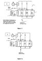
- FIG. 1 A traditional plant of the type described above is schematically illustrated in Figure 1 .
- a primary object of the present invention is to overcome the drawbacks of known plants by providing a plant operating with significantly higher energy efficiency.
- a second object of the invention is to provide plants capable of achieving the pressure changes enabled by known plants, using a much simpler and consequently less expensive design and one that is more reliable compared with similar known designs.
- An additional object of the invention is plants with a smaller compressor.
- a further object is to provide plants with compressors designed for continuous operation, more reliable than traditional compressors operating intermittently.
- the pressure changes are achieved by the same compressor through a switch of delivery with suction.
- the compressor achieves the different pressures via different delivery periods according to the amount of gas stored in the cylinders.
- the customer's vehicle will be supplied first with low-pressure methane, then with medium-pressure and finally with maximum-pressure gas. This will provide for the total mass of gas required to achieve maximum pressure to be delivered into the vehicle's tanks or cylinders, thus saving the energy that would be needed to bring the whole mass to maximum pressure.
- 1 indicates a gas compression plant of the type endowed with a gas compressor 2 and a cylinder casing 3.
- the compressor 2 is a one-stage apparatus that is fed natural gas from the pipeline through a suction conduit 9 which channels the compressed gas to a feed conduit 10.
- the pipeline gas enters the suction conduit 9 of the compressor 2 at an initial pressure of ca. 20 bar and exits the feed conduit 10 at a maximum pressure of ca. 290 bar.
- the pressure change from initial to final pressure is achieved by the compressor 2 in three successive compression stages, among which the total pressure difference is appropriately divided.
- the cylinder casing 3 is comprised of as many cylinders 4 as the compression steps or stages, each cylinder 4 storing compressed gas substantially at the maximum pressure achieved in each of the stages into which the total pressure difference has been subdivided.
- the plant 1 also includes means to feed the compressor 2, before the execution of each of said consecutive stages, with gas from the cylinder 4 that has been filled last. This is shown in greater detail in figures 3a , 3b and 3c , where the functional diagrams of the three phases of compression and storage are illustrated.
- the gas from the feed line 14 is compressed from the initial pipeline pressure [ca. 20 bar] to a low pressure LP of ca. 49 bar.
- the gas is compressed to the medium pressure MP of ca. 120 bar. Compression of the natural gas in the compressor 2 is achieved by sucking gas from the low-pressure LP cylinder 4, keeping open valve 12 and a valve 17 placed on a tract 20 of the conduit that connects the LP cylinder 4 to the suction conduit 9 of the compressor 2. An inlet valve 18 to the medium-pressure MP cylinder 4, and a valve 19 placed on a second branching 21, connecting the feed conduit 10 to the medium-pressure MP cylinder 4, are also open.
- the gas is compressed to the maximum pressure [ca. 290 bar].
- the compression is achieved by sucking gas from the medium-pressure MP cylinder 4, with valves 17 and 18 open.
- a valve 22 placed on a tract 23 of the conduit that connects the medium-pressure MP cylinder 4 to the suction conduit 9 of the compressor 2 via tract 20 and an inlet valve 24 to the high-pressure HP cylinder 4 positioned on a third branching 25 of the feed conduit 10 are also open.
- the filling of a vehicle's storage cylinder is represented in figure 4 .
- Operations begin with filling the vehicle's storage cylinder with gas at a pressure slightly greater than the pressure found inside it, by keeping open an interception valve 26 of a dispensing hose 28 and an outlet valve 27 of the low-pressure LP cylinder 4.
- the cylinder of the vehicle is filled from the medium-pressure MP cylinder 4, with valve 26 and an outlet valve 29 of the medium-pressure MP cylinder 4 being open.
- the plant 1 comprises cooling means 5 of the gas stored in the cylinders 4.
- the system can be embodied in a conventional cooling system with a compressor 31, whose function can be performed by the same compressor 2 compressing the natural gas.
- the cooling system can be provided with motors to power the compressor 31. These can be either separate or be the same as the motor 6 powering the natural gas compressor 2.
- the motors can be indifferently electrical or thermal.
- cooling can be provided by a high-thermal capacity fluid spraying system associated with the cylinders 4 in the cylinder casing 3.
- the cylinder s, stacked on racks can be sprinkled from above with a refrigerated water and ethyl alcohol solution by a system of nozzles; the solution, collected in a tub, can then be sucked by a pump that returns it to the cooling system to be cooled again.
- the system requires a casing for the racks and the tub.
- An alternative embodiment is one where cooling is provided by a tub containing a high-thermal capacity fluid in which the cylinders 4 are immersed.
- the cylinders 4, however packaged shall be placed into large, water-tight steel vessels filled with a water and ethyl alcohol solution from the cooling system: as in the case mentioned above, the fluid is returned to the fridge to be cooled again.
- filtered well water circulated periodically can be used as an alternative to the cooling system.
- the plant 1 is fitted with sensor means 8, operatively associated with compressor 2 and with the cylinders 4.
- said sensor means 8 switch off gas inlet into the compressor 2, by activating its connection to the downstream cylinder 4 and switch on the suction of the compressor 2 by activating its connection to the upstream cylinder 4 filled in the previous compression stage.
- the pressure of the individual stages is defined by customer habits.
- the minimum pressure in the storage cylinder of a vehicle at a filling station is about 30 bar. This dictates the low-pressure value, which will reasonably exceed 30 bar; a value of about 50 bar is considered suitable.
- the medium pressure is approx. 120 bar.
- a proper 49-120-294 progression is achieved by a constant compression ratio, equal to 2.45, starting from a pipeline pressure of 20 bar.
- a suitable compression ratio is calculated and the pressure progression is adjusted.
- a pressure adjustment stage shall be required to reach 20 bar, with a storage and a cooling stage.
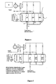
- FIG. 5 A basic drawing of such a plant is reported in figure 5 ; it envisages a pipeline pressure of 4 bar, common in Italy and requires an additional compressor with a compression ratio of 5.
- One additional advantage is that a single compressor 2 and a single compression stage subserve the storage of gas at intermediate pressures by acting only on the pressure difference between stages and only on a limited amount of gas, i.e. the amount of gas delivered to the cylinder casing 3.
- the overall lower compression ratio required of the compressor 2 enables use of small compressors 2, with lower plant and operating costs.
- the continuous operation design of the compressor 2 entails the additional advantage of greater plant 1 reliability.
- a further advantage is that the cylinders 4 can also serve as coolers.
Landscapes
- Engineering & Computer Science (AREA)
- Mechanical Engineering (AREA)
- General Engineering & Computer Science (AREA)
- Physics & Mathematics (AREA)
- Thermal Sciences (AREA)
- Filling Or Discharging Of Gas Storage Vessels (AREA)
- Processing Of Solid Wastes (AREA)
- Preparation Of Compounds By Using Micro-Organisms (AREA)
- Organic Low-Molecular-Weight Compounds And Preparation Thereof (AREA)
- Compressor (AREA)
Abstract
Description
- The present invention relates to the process of compression of natural gas for automotive use and more particularly to a high-energy efficiency automotive methane compression plant.
- The current technique in the sector of automotive methane compression plants envisages a pressure increase from the pressure found in the pipeline (which ranges from 4 bar to approx 40 bar) to 280 bar, required for filling operations, using a multistage compressor with intercooler.
- The system entails the construction of a compressor with suitable capacity for the (requirements of the plant, related to the dispensing capacity commonly required once in operation. A cooling phase is needed between stages to lower the initial temperature of the compressed gas in each stage, thus reducing energy consumption, and to protect the compressor's seal parts.
- These systems therefore require single-acting or double-acting multi-cylinder compressors designed so that the respective volumes are appropriate for the density variations in a capacity that must be identical in each individual stage.
- Prior art already knows such multi-cylinder compressors, disclosed for example by document FR 2503279, which is considered as the closest prior art, wherein a compressor group is shown which is provided with a plurality of compression stages compressors mounted on a single shaft. The compressors are provided with closable bypass lines in order to achieve low an idling power as possible as quickly as possible when starting-up or when changing to idling mode.
- Another example of such compressors is found in the document
EP 0757179 wherein it is shown a compressor apparatus for refrigerant circuits, which is provided with a turbocompressor with a plurality of compression stages mounted on a single shaft . The apparatus comprises mixer devices, interposed between two successive compressor stages, into which the main gas and infeed flows are introduced. The two flows are mixed in the mixer device in such a manner that the flow leaves the mixer device with a homogeneous temperature distribution and velocity distribution before working into the next stage of said turbocompressor having a plurality of compression stage In the prior art, and more particularly in the sector of automative methane compression plants, cooling requires large and consequently expensive systems, which considerably influence final plant cost. In fact they need to cool the gas predominantly with air or with water circuits. In addition, the compressor is subject to continuous starts and stops in relation to the gas withdrawn with each customer use. This is one of the principal factors affecting reliability, and requires appropriate overdimensioning in the design stage. - The operating problems of these plants increase at high ambient temperatures (e.g. tropical countries) by affecting the intercooler system.
- A traditional plant of the type described above is schematically illustrated in
Figure 1 . - A primary object of the present invention is to overcome the drawbacks of known plants by providing a plant operating with significantly higher energy efficiency.
- A second object of the invention is to provide plants capable of achieving the pressure changes enabled by known plants, using a much simpler and consequently less expensive design and one that is more reliable compared with similar known designs. An additional object of the invention is plants with a smaller compressor.
- A further object is to provide plants with compressors designed for continuous operation, more reliable than traditional compressors operating intermittently.
- In line with the invention such objects are met by a plant that - under
claim 1 and/or any of the directly or indirectly dependent claims- uses a one-stage compressor and suitable intermediate storing systems at different pressures, placed in a cooled environment. From the pipeline pressure the gas is brought to low pressure via a single compression stage, it is stored, brought to medium pressure and finally to the final pressure. - The pressure changes are achieved by the same compressor through a switch of delivery with suction. The compressor achieves the different pressures via different delivery periods according to the amount of gas stored in the cylinders.
- At the filling station, the customer's vehicle will be supplied first with low-pressure methane, then with medium-pressure and finally with maximum-pressure gas. This will provide for the total mass of gas required to achieve maximum pressure to be delivered into the vehicle's tanks or cylinders, thus saving the energy that would be needed to bring the whole mass to maximum pressure.
- The advantages of a plant constructed according to the disclosed invention are illustrated below in the detailed description of a preferred embodiment that is merely illustrative but does not delimit the plant, where :
-
figure 1 is a basic drawing of a conventional compression plant; -
figure 2 is a functional diagram of the plant fed at ca. 20 bar showing the different pressure levels; -
figure 3a is a functional diagram of the stage where the low-pressure cylinder is fed by gas from the pipeline; -
figure 3b is a functional diagram of the stage where the medium-pressure cylinder is fed by gas from the low-pressure cylinder; -
figure 3c is a functional diagram of the stage where the high-pressure cylinder is fed by gas from the medium-pressure cylinder; -
figure 4 is a functional diagram of the customer dispensing stage, with multiple, successive fillings from the three different cylinders; -
figure 5 is a basic drawing of a plant constructed according to the disclosed invention, endowed with a stage of adjustment to pipeline suction pressure. - In the figures of the attached drawings, 1 indicates a gas compression plant of the type endowed with a
gas compressor 2 and acylinder casing 3. - The
compressor 2 is a one-stage apparatus that is fed natural gas from the pipeline through asuction conduit 9 which channels the compressed gas to afeed conduit 10. The pipeline gas enters thesuction conduit 9 of thecompressor 2 at an initial pressure of ca. 20 bar and exits the feed conduit 10 at a maximum pressure of ca. 290 bar. The pressure change from initial to final pressure is achieved by thecompressor 2 in three successive compression stages, among which the total pressure difference is appropriately divided. - The
cylinder casing 3 is comprised of asmany cylinders 4 as the compression steps or stages, eachcylinder 4 storing compressed gas substantially at the maximum pressure achieved in each of the stages into which the total pressure difference has been subdivided. - The
plant 1 also includes means to feed thecompressor 2, before the execution of each of said consecutive stages, with gas from thecylinder 4 that has been filled last. This is shown in greater detail infigures 3a ,3b and 3c , where the functional diagrams of the three phases of compression and storage are illustrated. - As shown in
figure 3a , the gas from thefeed line 14 is compressed from the initial pipeline pressure [ca. 20 bar] to a low pressure LP of ca. 49 bar. - This is achieved by sucking natural gas from the
feed line 14, while aninlet valve 11 placed on said line, avalve 12 placed upstream of a first low-pressure LP cylinder 4, and avalve 13 placed on a first branching 15 connecting thefeed conduit 10 to the first low-pressure LP cylinder 4 are all open. - As illustrated in
figure 3b , the gas is compressed to the medium pressure MP of ca. 120 bar. Compression of the natural gas in thecompressor 2 is achieved by sucking gas from the low-pressure LP cylinder 4, keepingopen valve 12 and avalve 17 placed on atract 20 of the conduit that connects theLP cylinder 4 to thesuction conduit 9 of thecompressor 2. Aninlet valve 18 to the medium-pressure MP cylinder 4, and avalve 19 placed on a second branching 21, connecting thefeed conduit 10 to the medium-pressure MP cylinder 4, are also open. - As shown in
figure 3c the gas is compressed to the maximum pressure [ca. 290 bar]. The compression is achieved by sucking gas from the medium-pressure MP cylinder 4, withvalves valve 22 placed on atract 23 of the conduit that connects the medium-pressure MP cylinder 4 to thesuction conduit 9 of thecompressor 2 viatract 20 and aninlet valve 24 to the high-pressure HP cylinder 4 positioned on a third branching 25 of thefeed conduit 10 are also open. - The filling of a vehicle's storage cylinder is represented in
figure 4 . Operations begin with filling the vehicle's storage cylinder with gas at a pressure slightly greater than the pressure found inside it, by keeping open aninterception valve 26 of a dispensinghose 28 and anoutlet valve 27 of the low-pressure LP cylinder 4. - Once the low pressure has been achieved, the cylinder of the vehicle is filled from the medium-
pressure MP cylinder 4, withvalve 26 and anoutlet valve 29 of the medium-pressure MP cylinder 4 being open. - Once this step has been completed the cylinder of the vehicle is finally filled with gas from the high-
pressure HP cylinder 4, withvalve 26 and anoutlet valve 30 of the high-pressure HP cylinder 4 open. - In the description of the operation of the
plant 1, storage and delivery of natural gas are described as being independent of one another. Clearly, storage and delivery can be performed simultaneously. - The
plant 1 comprises cooling means 5 of the gas stored in thecylinders 4. The system can be embodied in a conventional cooling system with acompressor 31, whose function can be performed by thesame compressor 2 compressing the natural gas. - The cooling system can be provided with motors to power the
compressor 31. These can be either separate or be the same as themotor 6 powering thenatural gas compressor 2. - The motors can be indifferently electrical or thermal.
- Alternatively, cooling can be provided by a high-thermal capacity fluid spraying system associated with the
cylinders 4 in thecylinder casing 3. - In particular the cylinder s, stacked on racks, can be sprinkled from above with a refrigerated water and ethyl alcohol solution by a system of nozzles; the solution, collected in a tub, can then be sucked by a pump that returns it to the cooling system to be cooled again. The system requires a casing for the racks and the tub.
- An alternative embodiment is one where cooling is provided by a tub containing a high-thermal capacity fluid in which the
cylinders 4 are immersed. - More in particular the
cylinders 4, however packaged, shall be placed into large, water-tight steel vessels filled with a water and ethyl alcohol solution from the cooling system: as in the case mentioned above, the fluid is returned to the fridge to be cooled again. Where available, filtered well water circulated periodically can be used as an alternative to the cooling system. - In either case, it is the cylinders that work as heat exchangers. Therefore devices that increase the heat exchange, e.g. fins, can be added if needed.
- According to the disclosed invention, the
plant 1 is fitted with sensor means 8, operatively associated withcompressor 2 and with thecylinders 4. Upon detecting the achievement of the maximum pressure in eachcylinder 4, said sensor means 8 switch off gas inlet into thecompressor 2, by activating its connection to thedownstream cylinder 4 and switch on the suction of thecompressor 2 by activating its connection to theupstream cylinder 4 filled in the previous compression stage. - The pressure of the individual stages is defined by customer habits. The minimum pressure in the storage cylinder of a vehicle at a filling station is about 30 bar. This dictates the low-pressure value, which will reasonably exceed 30 bar; a value of about 50 bar is considered suitable.
- Since the maximum allowed filling pressure is usually around 300 bar, the medium pressure is approx. 120 bar.
- Since a single compressor is used, a proper 49-120-294 progression is achieved by a constant compression ratio, equal to 2.45, starting from a pipeline pressure of 20 bar. For higher pipeline pressures a suitable compression ratio is calculated and the pressure progression is adjusted. For lower pipeline pressures, a pressure adjustment stage shall be required to reach 20 bar, with a storage and a cooling stage.
- A basic drawing of such a plant is reported in
figure 5 ; it envisages a pipeline pressure of 4 bar, common in Italy and requires an additional compressor with a compression ratio of 5. - The disclosed design fully meets the above requirements and also achieves additional advantages.
- One additional advantage is that a
single compressor 2 and a single compression stage subserve the storage of gas at intermediate pressures by acting only on the pressure difference between stages and only on a limited amount of gas, i.e. the amount of gas delivered to thecylinder casing 3. - This results in considerable energy savings.
- In addition, the overall lower compression ratio required of the
compressor 2 enables use ofsmall compressors 2, with lower plant and operating costs. - The continuous operation design of the
compressor 2 entails the additional advantage ofgreater plant 1 reliability. - A further advantage is that the
cylinders 4 can also serve as coolers. - Several changes and modifications of the invention can be implemented by experts in the field, who will choose the most appropriate dimension and construction materials according to the type of application. Such changes are thus to be viewed as inherent to the invention and as encompassing the object of the claims below.
Claims (13)
- A gas compression plant of the type comprising at least one gas compressor (2) and at least a cylinder casing (3), characterized in that said compressor (2) is a one stage compressor which achieves complete compression of the gas through at least two consecutive compression steps, said consecutive compression steps are achieved by means of successive compression steps through said one stage compressor (2), said cylinder casing (3) comprising as many cylinders (4) as there are compression steps,
said cylinders (4) storing gas compressed substantially to the maximum pressure achieved in each of said steps, and feed delivery means (7) to dispense compressed gas to fill vehicle's storage cylinder; said plaint being provided with means to feed said compressor (2), prior to the execution of each successive steps, with gas from the previous compression step, stored in the respective cylinder (4). - A plant, according to claim 1, characterized in that it comprises cooling means (5) of the gas stored in said cylinders (4).
- A plant, according to claim 2, characterized in that said cooling means (5) comprise a cooling system.
- A plant, according to claim 2, characterized in that said cooling means (5) comprise a high-thermal capacity fluid spraying system associated with the cylinders (4) arranged in said cylinder casing (3).
- A plant, according to claim 2, characterized in that said cooling means (5) comprise a tub containing a high-thermal capacity fluid in which said cylinders (4) are immersed.
- A plant, according to claim 3, characterized in that said cooling system comprises a compressor (2), said gas compressor (2) being the compressor (2) powering the cooling system.
- A plant, according to claim 3, characterized in that said cooling system comprises motors (6), said gas compressor (2) being powered by motors (6) that also power the cooling system.
- A plant, according to claim 1, characterized in that said compressor (2) is powered by electrical motors (6).
- A plant, according to claim 1, characterized in that said compressor (2) is powered by thermal motors (6).
- A plant, according to claim 1, characterized in that said cylinders (4) simultaneously store and deliver compressed gas.
- A plant, according to claim 1, characterized in that said complete compression is achieved through three consecutive compression steps.
- A plant, according to claim 1, characterized in that it comprises sensor means (8) operatively associated with said compressor (2) and with said cylinders (4) which upon detecting the achievement of the maximum pressure in the different cylinders (4) switch off gas inlet into the compressor 2 by activating its connection to the downstream cylinder (4) and switch on the suction of the compressor (2) by activating its connection to the upstream cylinder (4) filled last.
- A plant, according to claim 1, characterized in that said compressed gas is natural gas for automotive vehicles.
Applications Claiming Priority (2)
| Application Number | Priority Date | Filing Date | Title |
|---|---|---|---|
| IT000063A ITAN20070063A1 (en) | 2007-12-04 | 2007-12-04 | HIGH ENERGY EFFICIENCY PLANT FOR METHANE COMPRESSION FOR SELF-TRAFFICING |
| PCT/IT2008/000736 WO2009072160A2 (en) | 2007-12-04 | 2008-12-01 | High-energy efficiency plant for automotive methane compression |
Publications (2)
| Publication Number | Publication Date |
|---|---|
| EP2232076A2 EP2232076A2 (en) | 2010-09-29 |
| EP2232076B1 true EP2232076B1 (en) | 2011-06-22 |
Family
ID=40315320
Family Applications (1)
| Application Number | Title | Priority Date | Filing Date |
|---|---|---|---|
| EP08857951A Not-in-force EP2232076B1 (en) | 2007-12-04 | 2008-12-01 | High-energy efficiency plant for automotive methane compression |
Country Status (7)
| Country | Link |
|---|---|
| EP (1) | EP2232076B1 (en) |
| CN (1) | CN101889142A (en) |
| AT (1) | ATE513994T1 (en) |
| BR (1) | BRPI0820001A2 (en) |
| ES (1) | ES2368107T3 (en) |
| IT (1) | ITAN20070063A1 (en) |
| WO (1) | WO2009072160A2 (en) |
Families Citing this family (6)
| Publication number | Priority date | Publication date | Assignee | Title |
|---|---|---|---|---|
| WO2013116526A1 (en) | 2012-01-31 | 2013-08-08 | J-W Power Company | Cng fueling system |
| US10851944B2 (en) | 2012-01-31 | 2020-12-01 | J-W Power Company | CNG fueling system |
| US10018304B2 (en) | 2012-01-31 | 2018-07-10 | J-W Power Company | CNG fueling system |
| US9816497B2 (en) | 2013-02-03 | 2017-11-14 | Go Natural Cng, Llc | Compressors for natural gas and related devices, systems, and methods |
| WO2014121251A2 (en) * | 2013-02-04 | 2014-08-07 | Parker-Hannifin Corporation | Gas compressor |
| US12305651B2 (en) * | 2021-06-14 | 2025-05-20 | Air Products And Chemicals, Inc. | Process and apparatus for operating a compression system |
Family Cites Families (3)
| Publication number | Priority date | Publication date | Assignee | Title |
|---|---|---|---|---|
| GB315725A (en) * | 1928-07-16 | 1929-12-24 | International General Electric Y | |
| DE3114522A1 (en) * | 1981-04-07 | 1982-11-18 | Gebrüder Sulzer AG, 8401 Winterthur | Turbocompressor unit |
| DE59510130D1 (en) * | 1995-07-31 | 2002-05-02 | Man Turbomasch Ag Ghh Borsig | compression device |
-
2007
- 2007-12-04 IT IT000063A patent/ITAN20070063A1/en unknown
-
2008
- 2008-12-01 EP EP08857951A patent/EP2232076B1/en not_active Not-in-force
- 2008-12-01 BR BRPI0820001-7A patent/BRPI0820001A2/en not_active IP Right Cessation
- 2008-12-01 ES ES08857951T patent/ES2368107T3/en active Active
- 2008-12-01 WO PCT/IT2008/000736 patent/WO2009072160A2/en not_active Ceased
- 2008-12-01 CN CN2008801193269A patent/CN101889142A/en active Pending
- 2008-12-01 AT AT08857951T patent/ATE513994T1/en not_active IP Right Cessation
Also Published As
| Publication number | Publication date |
|---|---|
| BRPI0820001A2 (en) | 2015-05-19 |
| CN101889142A (en) | 2010-11-17 |
| EP2232076A2 (en) | 2010-09-29 |
| WO2009072160A3 (en) | 2009-09-17 |
| ATE513994T1 (en) | 2011-07-15 |
| ES2368107T3 (en) | 2011-11-14 |
| ITAN20070063A1 (en) | 2009-06-05 |
| WO2009072160A2 (en) | 2009-06-11 |
Similar Documents
| Publication | Publication Date | Title |
|---|---|---|
| TW293869B (en) | ||
| CA2379766C (en) | Method and apparatus for compressing a gas to a high pressure | |
| AU749463B2 (en) | Refrigeration system with liquid injection desuperheating | |
| JP6832869B2 (en) | Gas handling systems and methods for efficiently managing changes in gas conditions | |
| EP2729705B1 (en) | Gas balanced brayton cycle cold water vapor cryopump | |
| US20080196384A1 (en) | Recipicating compressor with inlet booster for cng station and refueling motor vehicles | |
| WO2009072160A2 (en) | High-energy efficiency plant for automotive methane compression | |
| EP2307694A1 (en) | Gas supply systems for gas engines | |
| US20130177393A1 (en) | Hybrid Compressor System and Methods | |
| US8839829B2 (en) | Reciprocating compressor with inlet booster for CNG station and refueling motor vehicles | |
| EP3508773A1 (en) | Method for providing pressurized gas to consumers and corresponding compressor arrangement at variable suction conditions | |
| US7213405B2 (en) | Two-stage linear compressor | |
| CN103946654A (en) | Compression method and air separation | |
| US5802874A (en) | Process and apparatus for liquefying low boiling gas such as nitrogen | |
| CN101548142B (en) | Refrigerant charge storage | |
| CN208871898U (en) | Refrigerant circulation system | |
| AU5849299A (en) | CO2-operated air conditioning system for a motor vehicle | |
| US20140174709A1 (en) | Engine inlet air cooling system and method | |
| HK1150872A (en) | High-energy efficiency plant for automotive methane compression | |
| WO1997016648A1 (en) | Improvements in and relating to single screw compressors | |
| US8337176B2 (en) | Tandem compressors with common intermediate port |
Legal Events
| Date | Code | Title | Description |
|---|---|---|---|
| PUAI | Public reference made under article 153(3) epc to a published international application that has entered the european phase |
Free format text: ORIGINAL CODE: 0009012 |
|
| 17P | Request for examination filed |
Effective date: 20100611 |
|
| AK | Designated contracting states |
Kind code of ref document: A2 Designated state(s): AT BE BG CH CY CZ DE DK EE ES FI FR GB GR HR HU IE IS IT LI LT LU LV MC MT NL NO PL PT RO SE SI SK TR |
|
| AX | Request for extension of the european patent |
Extension state: AL BA MK RS |
|
| RAP1 | Party data changed (applicant data changed or rights of an application transferred) |
Owner name: S.TRA.TE.G.I.E. S.R.L. |
|
| GRAP | Despatch of communication of intention to grant a patent |
Free format text: ORIGINAL CODE: EPIDOSNIGR1 |
|
| DAX | Request for extension of the european patent (deleted) | ||
| GRAS | Grant fee paid |
Free format text: ORIGINAL CODE: EPIDOSNIGR3 |
|
| GRAA | (expected) grant |
Free format text: ORIGINAL CODE: 0009210 |
|
| AK | Designated contracting states |
Kind code of ref document: B1 Designated state(s): AT BE BG CH CY CZ DE DK EE ES FI FR GB GR HR HU IE IS IT LI LT LU LV MC MT NL NO PL PT RO SE SI SK TR |
|
| REG | Reference to a national code |
Ref country code: GB Ref legal event code: FG4D |
|
| REG | Reference to a national code |
Ref country code: CH Ref legal event code: EP |
|
| REG | Reference to a national code |
Ref country code: IE Ref legal event code: FG4D |
|
| REG | Reference to a national code |
Ref country code: DE Ref legal event code: R096 Ref document number: 602008007852 Country of ref document: DE Effective date: 20110811 |
|
| REG | Reference to a national code |
Ref country code: SE Ref legal event code: TRGR |
|
| REG | Reference to a national code |
Ref country code: NL Ref legal event code: VDEP Effective date: 20110622 |
|
| PG25 | Lapsed in a contracting state [announced via postgrant information from national office to epo] |
Ref country code: HR Free format text: LAPSE BECAUSE OF FAILURE TO SUBMIT A TRANSLATION OF THE DESCRIPTION OR TO PAY THE FEE WITHIN THE PRESCRIBED TIME-LIMIT Effective date: 20110622 Ref country code: LT Free format text: LAPSE BECAUSE OF FAILURE TO SUBMIT A TRANSLATION OF THE DESCRIPTION OR TO PAY THE FEE WITHIN THE PRESCRIBED TIME-LIMIT Effective date: 20110622 Ref country code: NO Free format text: LAPSE BECAUSE OF FAILURE TO SUBMIT A TRANSLATION OF THE DESCRIPTION OR TO PAY THE FEE WITHIN THE PRESCRIBED TIME-LIMIT Effective date: 20110922 |
|
| REG | Reference to a national code |
Ref country code: ES Ref legal event code: FG2A Ref document number: 2368107 Country of ref document: ES Kind code of ref document: T3 Effective date: 20111114 |
|
| PG25 | Lapsed in a contracting state [announced via postgrant information from national office to epo] |
Ref country code: AT Free format text: LAPSE BECAUSE OF FAILURE TO SUBMIT A TRANSLATION OF THE DESCRIPTION OR TO PAY THE FEE WITHIN THE PRESCRIBED TIME-LIMIT Effective date: 20110622 Ref country code: GR Free format text: LAPSE BECAUSE OF FAILURE TO SUBMIT A TRANSLATION OF THE DESCRIPTION OR TO PAY THE FEE WITHIN THE PRESCRIBED TIME-LIMIT Effective date: 20110923 Ref country code: SI Free format text: LAPSE BECAUSE OF FAILURE TO SUBMIT A TRANSLATION OF THE DESCRIPTION OR TO PAY THE FEE WITHIN THE PRESCRIBED TIME-LIMIT Effective date: 20110622 Ref country code: LV Free format text: LAPSE BECAUSE OF FAILURE TO SUBMIT A TRANSLATION OF THE DESCRIPTION OR TO PAY THE FEE WITHIN THE PRESCRIBED TIME-LIMIT Effective date: 20110622 Ref country code: FI Free format text: LAPSE BECAUSE OF FAILURE TO SUBMIT A TRANSLATION OF THE DESCRIPTION OR TO PAY THE FEE WITHIN THE PRESCRIBED TIME-LIMIT Effective date: 20110622 Ref country code: CY Free format text: LAPSE BECAUSE OF FAILURE TO SUBMIT A TRANSLATION OF THE DESCRIPTION OR TO PAY THE FEE WITHIN THE PRESCRIBED TIME-LIMIT Effective date: 20110622 |
|
| PG25 | Lapsed in a contracting state [announced via postgrant information from national office to epo] |
Ref country code: BE Free format text: LAPSE BECAUSE OF FAILURE TO SUBMIT A TRANSLATION OF THE DESCRIPTION OR TO PAY THE FEE WITHIN THE PRESCRIBED TIME-LIMIT Effective date: 20110622 Ref country code: NL Free format text: LAPSE BECAUSE OF FAILURE TO SUBMIT A TRANSLATION OF THE DESCRIPTION OR TO PAY THE FEE WITHIN THE PRESCRIBED TIME-LIMIT Effective date: 20110622 |
|
| PG25 | Lapsed in a contracting state [announced via postgrant information from national office to epo] |
Ref country code: CZ Free format text: LAPSE BECAUSE OF FAILURE TO SUBMIT A TRANSLATION OF THE DESCRIPTION OR TO PAY THE FEE WITHIN THE PRESCRIBED TIME-LIMIT Effective date: 20110622 Ref country code: PT Free format text: LAPSE BECAUSE OF FAILURE TO SUBMIT A TRANSLATION OF THE DESCRIPTION OR TO PAY THE FEE WITHIN THE PRESCRIBED TIME-LIMIT Effective date: 20111024 Ref country code: IS Free format text: LAPSE BECAUSE OF FAILURE TO SUBMIT A TRANSLATION OF THE DESCRIPTION OR TO PAY THE FEE WITHIN THE PRESCRIBED TIME-LIMIT Effective date: 20111022 Ref country code: EE Free format text: LAPSE BECAUSE OF FAILURE TO SUBMIT A TRANSLATION OF THE DESCRIPTION OR TO PAY THE FEE WITHIN THE PRESCRIBED TIME-LIMIT Effective date: 20110622 |
|
| PG25 | Lapsed in a contracting state [announced via postgrant information from national office to epo] |
Ref country code: PL Free format text: LAPSE BECAUSE OF FAILURE TO SUBMIT A TRANSLATION OF THE DESCRIPTION OR TO PAY THE FEE WITHIN THE PRESCRIBED TIME-LIMIT Effective date: 20110622 Ref country code: SK Free format text: LAPSE BECAUSE OF FAILURE TO SUBMIT A TRANSLATION OF THE DESCRIPTION OR TO PAY THE FEE WITHIN THE PRESCRIBED TIME-LIMIT Effective date: 20110622 Ref country code: RO Free format text: LAPSE BECAUSE OF FAILURE TO SUBMIT A TRANSLATION OF THE DESCRIPTION OR TO PAY THE FEE WITHIN THE PRESCRIBED TIME-LIMIT Effective date: 20110622 |
|
| PLBE | No opposition filed within time limit |
Free format text: ORIGINAL CODE: 0009261 |
|
| STAA | Information on the status of an ep patent application or granted ep patent |
Free format text: STATUS: NO OPPOSITION FILED WITHIN TIME LIMIT |
|
| 26N | No opposition filed |
Effective date: 20120323 |
|
| PG25 | Lapsed in a contracting state [announced via postgrant information from national office to epo] |
Ref country code: DK Free format text: LAPSE BECAUSE OF FAILURE TO SUBMIT A TRANSLATION OF THE DESCRIPTION OR TO PAY THE FEE WITHIN THE PRESCRIBED TIME-LIMIT Effective date: 20110622 |
|
| REG | Reference to a national code |
Ref country code: DE Ref legal event code: R097 Ref document number: 602008007852 Country of ref document: DE Effective date: 20120323 |
|
| PG25 | Lapsed in a contracting state [announced via postgrant information from national office to epo] |
Ref country code: MC Free format text: LAPSE BECAUSE OF NON-PAYMENT OF DUE FEES Effective date: 20111231 |
|
| REG | Reference to a national code |
Ref country code: IE Ref legal event code: MM4A |
|
| PG25 | Lapsed in a contracting state [announced via postgrant information from national office to epo] |
Ref country code: IE Free format text: LAPSE BECAUSE OF NON-PAYMENT OF DUE FEES Effective date: 20111201 |
|
| PG25 | Lapsed in a contracting state [announced via postgrant information from national office to epo] |
Ref country code: MT Free format text: LAPSE BECAUSE OF FAILURE TO SUBMIT A TRANSLATION OF THE DESCRIPTION OR TO PAY THE FEE WITHIN THE PRESCRIBED TIME-LIMIT Effective date: 20110622 |
|
| PG25 | Lapsed in a contracting state [announced via postgrant information from national office to epo] |
Ref country code: LU Free format text: LAPSE BECAUSE OF NON-PAYMENT OF DUE FEES Effective date: 20111201 |
|
| PG25 | Lapsed in a contracting state [announced via postgrant information from national office to epo] |
Ref country code: BG Free format text: LAPSE BECAUSE OF FAILURE TO SUBMIT A TRANSLATION OF THE DESCRIPTION OR TO PAY THE FEE WITHIN THE PRESCRIBED TIME-LIMIT Effective date: 20110922 |
|
| REG | Reference to a national code |
Ref country code: CH Ref legal event code: PL |
|
| GBPC | Gb: european patent ceased through non-payment of renewal fee |
Effective date: 20121201 |
|
| PG25 | Lapsed in a contracting state [announced via postgrant information from national office to epo] |
Ref country code: TR Free format text: LAPSE BECAUSE OF FAILURE TO SUBMIT A TRANSLATION OF THE DESCRIPTION OR TO PAY THE FEE WITHIN THE PRESCRIBED TIME-LIMIT Effective date: 20110622 |
|
| PG25 | Lapsed in a contracting state [announced via postgrant information from national office to epo] |
Ref country code: CH Free format text: LAPSE BECAUSE OF NON-PAYMENT OF DUE FEES Effective date: 20121231 Ref country code: LI Free format text: LAPSE BECAUSE OF NON-PAYMENT OF DUE FEES Effective date: 20121231 Ref country code: HU Free format text: LAPSE BECAUSE OF FAILURE TO SUBMIT A TRANSLATION OF THE DESCRIPTION OR TO PAY THE FEE WITHIN THE PRESCRIBED TIME-LIMIT Effective date: 20110622 |
|
| PG25 | Lapsed in a contracting state [announced via postgrant information from national office to epo] |
Ref country code: GB Free format text: LAPSE BECAUSE OF NON-PAYMENT OF DUE FEES Effective date: 20121201 |
|
| PGFP | Annual fee paid to national office [announced via postgrant information from national office to epo] |
Ref country code: SE Payment date: 20141219 Year of fee payment: 7 Ref country code: ES Payment date: 20141226 Year of fee payment: 7 Ref country code: DE Payment date: 20141211 Year of fee payment: 7 |
|
| PGFP | Annual fee paid to national office [announced via postgrant information from national office to epo] |
Ref country code: FR Payment date: 20141219 Year of fee payment: 7 |
|
| REG | Reference to a national code |
Ref country code: DE Ref legal event code: R119 Ref document number: 602008007852 Country of ref document: DE |
|
| REG | Reference to a national code |
Ref country code: SE Ref legal event code: EUG |
|
| PG25 | Lapsed in a contracting state [announced via postgrant information from national office to epo] |
Ref country code: SE Free format text: LAPSE BECAUSE OF NON-PAYMENT OF DUE FEES Effective date: 20151202 |
|
| REG | Reference to a national code |
Ref country code: FR Ref legal event code: ST Effective date: 20160831 |
|
| PG25 | Lapsed in a contracting state [announced via postgrant information from national office to epo] |
Ref country code: DE Free format text: LAPSE BECAUSE OF NON-PAYMENT OF DUE FEES Effective date: 20160701 |
|
| PG25 | Lapsed in a contracting state [announced via postgrant information from national office to epo] |
Ref country code: FR Free format text: LAPSE BECAUSE OF NON-PAYMENT OF DUE FEES Effective date: 20151231 |
|
| PG25 | Lapsed in a contracting state [announced via postgrant information from national office to epo] |
Ref country code: ES Free format text: LAPSE BECAUSE OF NON-PAYMENT OF DUE FEES Effective date: 20151202 |
|
| PGFP | Annual fee paid to national office [announced via postgrant information from national office to epo] |
Ref country code: IT Payment date: 20171222 Year of fee payment: 10 |
|
| PG25 | Lapsed in a contracting state [announced via postgrant information from national office to epo] |
Ref country code: IT Free format text: LAPSE BECAUSE OF NON-PAYMENT OF DUE FEES Effective date: 20181201 |