EP2232076B1 - Anlage mit hoher energieausbeute für kraftfahrzeugmethanverdichtung - Google Patents
Anlage mit hoher energieausbeute für kraftfahrzeugmethanverdichtung Download PDFInfo
- Publication number
- EP2232076B1 EP2232076B1 EP08857951A EP08857951A EP2232076B1 EP 2232076 B1 EP2232076 B1 EP 2232076B1 EP 08857951 A EP08857951 A EP 08857951A EP 08857951 A EP08857951 A EP 08857951A EP 2232076 B1 EP2232076 B1 EP 2232076B1
- Authority
- EP
- European Patent Office
- Prior art keywords
- compressor
- gas
- plant
- compression
- cylinders
- Prior art date
- Legal status (The legal status is an assumption and is not a legal conclusion. Google has not performed a legal analysis and makes no representation as to the accuracy of the status listed.)
- Not-in-force
Links
Images


Classifications
-
- F—MECHANICAL ENGINEERING; LIGHTING; HEATING; WEAPONS; BLASTING
- F04—POSITIVE - DISPLACEMENT MACHINES FOR LIQUIDS; PUMPS FOR LIQUIDS OR ELASTIC FLUIDS
- F04D—NON-POSITIVE-DISPLACEMENT PUMPS
- F04D29/00—Details, component parts, or accessories
- F04D29/58—Cooling; Heating; Diminishing heat transfer
- F04D29/582—Cooling; Heating; Diminishing heat transfer specially adapted for elastic fluid pumps
- F04D29/584—Cooling; Heating; Diminishing heat transfer specially adapted for elastic fluid pumps cooling or heating the machine
-
- F—MECHANICAL ENGINEERING; LIGHTING; HEATING; WEAPONS; BLASTING
- F04—POSITIVE - DISPLACEMENT MACHINES FOR LIQUIDS; PUMPS FOR LIQUIDS OR ELASTIC FLUIDS
- F04B—POSITIVE-DISPLACEMENT MACHINES FOR LIQUIDS; PUMPS
- F04B49/00—Control, e.g. of pump delivery, or pump pressure of, or safety measures for, machines, pumps, or pumping installations, not otherwise provided for, or of interest apart from, groups F04B1/00 - F04B47/00
- F04B49/007—Installations or systems with two or more pumps or pump cylinders, wherein the flow-path through the stages can be changed, e.g. from series to parallel
-
- F—MECHANICAL ENGINEERING; LIGHTING; HEATING; WEAPONS; BLASTING
- F04—POSITIVE - DISPLACEMENT MACHINES FOR LIQUIDS; PUMPS FOR LIQUIDS OR ELASTIC FLUIDS
- F04D—NON-POSITIVE-DISPLACEMENT PUMPS
- F04D27/00—Control, e.g. regulation, of pumps, pumping installations or pumping systems specially adapted for elastic fluids
- F04D27/02—Surge control
- F04D27/0269—Surge control by changing flow path between different stages or between a plurality of compressors; load distribution between compressors
-
- F—MECHANICAL ENGINEERING; LIGHTING; HEATING; WEAPONS; BLASTING
- F04—POSITIVE - DISPLACEMENT MACHINES FOR LIQUIDS; PUMPS FOR LIQUIDS OR ELASTIC FLUIDS
- F04D—NON-POSITIVE-DISPLACEMENT PUMPS
- F04D29/00—Details, component parts, or accessories
- F04D29/58—Cooling; Heating; Diminishing heat transfer
- F04D29/582—Cooling; Heating; Diminishing heat transfer specially adapted for elastic fluid pumps
- F04D29/5826—Cooling at least part of the working fluid in a heat exchanger
Definitions
- the present invention relates to the process of compression of natural gas for automotive use and more particularly to a high-energy efficiency automotive methane compression plant.
- the current technique in the sector of automotive methane compression plants envisages a pressure increase from the pressure found in the pipeline (which ranges from 4 bar to approx 40 bar) to 280 bar, required for filling operations, using a multistage compressor with intercooler.
- the system entails the construction of a compressor with suitable capacity for the (requirements of the plant, related to the dispensing capacity commonly required once in operation.
- a cooling phase is needed between stages to lower the initial temperature of the compressed gas in each stage, thus reducing energy consumption, and to protect the compressor's seal parts.
- compressor apparatus for refrigerant circuits, which is provided with a turbocompressor with a plurality of compression stages mounted on a single shaft .
- the apparatus comprises mixer devices, interposed between two successive compressor stages, into which the main gas and infeed flows are introduced.
- the two flows are mixed in the mixer device in such a manner that the flow leaves the mixer device with a homogeneous temperature distribution and velocity distribution before working into the next stage of said turbocompressor having a plurality of compression stage
- cooling requires large and consequently expensive systems, which considerably influence final plant cost. In fact they need to cool the gas predominantly with air or with water circuits.
- the compressor is subject to continuous starts and stops in relation to the gas withdrawn with each customer use. This is one of the principal factors affecting reliability, and requires appropriate overdimensioning in the design stage.
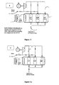
- FIG. 1 A traditional plant of the type described above is schematically illustrated in Figure 1 .
- a primary object of the present invention is to overcome the drawbacks of known plants by providing a plant operating with significantly higher energy efficiency.
- a second object of the invention is to provide plants capable of achieving the pressure changes enabled by known plants, using a much simpler and consequently less expensive design and one that is more reliable compared with similar known designs.
- An additional object of the invention is plants with a smaller compressor.
- a further object is to provide plants with compressors designed for continuous operation, more reliable than traditional compressors operating intermittently.
- the pressure changes are achieved by the same compressor through a switch of delivery with suction.
- the compressor achieves the different pressures via different delivery periods according to the amount of gas stored in the cylinders.
- the customer's vehicle will be supplied first with low-pressure methane, then with medium-pressure and finally with maximum-pressure gas. This will provide for the total mass of gas required to achieve maximum pressure to be delivered into the vehicle's tanks or cylinders, thus saving the energy that would be needed to bring the whole mass to maximum pressure.
- 1 indicates a gas compression plant of the type endowed with a gas compressor 2 and a cylinder casing 3.
- the compressor 2 is a one-stage apparatus that is fed natural gas from the pipeline through a suction conduit 9 which channels the compressed gas to a feed conduit 10.
- the pipeline gas enters the suction conduit 9 of the compressor 2 at an initial pressure of ca. 20 bar and exits the feed conduit 10 at a maximum pressure of ca. 290 bar.
- the pressure change from initial to final pressure is achieved by the compressor 2 in three successive compression stages, among which the total pressure difference is appropriately divided.
- the cylinder casing 3 is comprised of as many cylinders 4 as the compression steps or stages, each cylinder 4 storing compressed gas substantially at the maximum pressure achieved in each of the stages into which the total pressure difference has been subdivided.
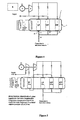
- the plant 1 also includes means to feed the compressor 2, before the execution of each of said consecutive stages, with gas from the cylinder 4 that has been filled last. This is shown in greater detail in figures 3a , 3b and 3c , where the functional diagrams of the three phases of compression and storage are illustrated.
- the gas from the feed line 14 is compressed from the initial pipeline pressure [ca. 20 bar] to a low pressure LP of ca. 49 bar.
- the gas is compressed to the medium pressure MP of ca. 120 bar. Compression of the natural gas in the compressor 2 is achieved by sucking gas from the low-pressure LP cylinder 4, keeping open valve 12 and a valve 17 placed on a tract 20 of the conduit that connects the LP cylinder 4 to the suction conduit 9 of the compressor 2. An inlet valve 18 to the medium-pressure MP cylinder 4, and a valve 19 placed on a second branching 21, connecting the feed conduit 10 to the medium-pressure MP cylinder 4, are also open.
- the gas is compressed to the maximum pressure [ca. 290 bar].
- the compression is achieved by sucking gas from the medium-pressure MP cylinder 4, with valves 17 and 18 open.
- a valve 22 placed on a tract 23 of the conduit that connects the medium-pressure MP cylinder 4 to the suction conduit 9 of the compressor 2 via tract 20 and an inlet valve 24 to the high-pressure HP cylinder 4 positioned on a third branching 25 of the feed conduit 10 are also open.
- the filling of a vehicle's storage cylinder is represented in figure 4 .
- Operations begin with filling the vehicle's storage cylinder with gas at a pressure slightly greater than the pressure found inside it, by keeping open an interception valve 26 of a dispensing hose 28 and an outlet valve 27 of the low-pressure LP cylinder 4.
- the cylinder of the vehicle is filled from the medium-pressure MP cylinder 4, with valve 26 and an outlet valve 29 of the medium-pressure MP cylinder 4 being open.
- the plant 1 comprises cooling means 5 of the gas stored in the cylinders 4.
- the system can be embodied in a conventional cooling system with a compressor 31, whose function can be performed by the same compressor 2 compressing the natural gas.
- the cooling system can be provided with motors to power the compressor 31. These can be either separate or be the same as the motor 6 powering the natural gas compressor 2.
- the motors can be indifferently electrical or thermal.
- cooling can be provided by a high-thermal capacity fluid spraying system associated with the cylinders 4 in the cylinder casing 3.
- the cylinder s, stacked on racks can be sprinkled from above with a refrigerated water and ethyl alcohol solution by a system of nozzles; the solution, collected in a tub, can then be sucked by a pump that returns it to the cooling system to be cooled again.
- the system requires a casing for the racks and the tub.
- An alternative embodiment is one where cooling is provided by a tub containing a high-thermal capacity fluid in which the cylinders 4 are immersed.
- the cylinders 4, however packaged shall be placed into large, water-tight steel vessels filled with a water and ethyl alcohol solution from the cooling system: as in the case mentioned above, the fluid is returned to the fridge to be cooled again.
- filtered well water circulated periodically can be used as an alternative to the cooling system.
- the plant 1 is fitted with sensor means 8, operatively associated with compressor 2 and with the cylinders 4.
- said sensor means 8 switch off gas inlet into the compressor 2, by activating its connection to the downstream cylinder 4 and switch on the suction of the compressor 2 by activating its connection to the upstream cylinder 4 filled in the previous compression stage.
- the pressure of the individual stages is defined by customer habits.
- the minimum pressure in the storage cylinder of a vehicle at a filling station is about 30 bar. This dictates the low-pressure value, which will reasonably exceed 30 bar; a value of about 50 bar is considered suitable.
- the medium pressure is approx. 120 bar.
- a proper 49-120-294 progression is achieved by a constant compression ratio, equal to 2.45, starting from a pipeline pressure of 20 bar.
- a suitable compression ratio is calculated and the pressure progression is adjusted.
- a pressure adjustment stage shall be required to reach 20 bar, with a storage and a cooling stage.
- FIG. 5 A basic drawing of such a plant is reported in figure 5 ; it envisages a pipeline pressure of 4 bar, common in Italy and requires an additional compressor with a compression ratio of 5.
- One additional advantage is that a single compressor 2 and a single compression stage subserve the storage of gas at intermediate pressures by acting only on the pressure difference between stages and only on a limited amount of gas, i.e. the amount of gas delivered to the cylinder casing 3.
- the overall lower compression ratio required of the compressor 2 enables use of small compressors 2, with lower plant and operating costs.
- the continuous operation design of the compressor 2 entails the additional advantage of greater plant 1 reliability.
- a further advantage is that the cylinders 4 can also serve as coolers.
Landscapes
- Engineering & Computer Science (AREA)
- Mechanical Engineering (AREA)
- General Engineering & Computer Science (AREA)
- Physics & Mathematics (AREA)
- Thermal Sciences (AREA)
- Filling Or Discharging Of Gas Storage Vessels (AREA)
- Processing Of Solid Wastes (AREA)
- Compressor (AREA)
- Preparation Of Compounds By Using Micro-Organisms (AREA)
- Organic Low-Molecular-Weight Compounds And Preparation Thereof (AREA)
Claims (13)
- Eine Gaskompressionsanlage der Art, die mindestens einen Gaskompressor (2) und mindestens ein Zylindergehäuse (3) umfasst, gekennzeichnet dadurch, dass es sich bei besagtem Kompressor (2) um einen einstufigen Kompressor handelt, der die völlige Kompression des Gases mithilfe mindestens zweier aufeinander folgender Kompressionsschritte erreicht; besagte aufeinander folgenden Kompressionsschritte werden mithilfe aufeinander folgender Kompressionsschritte durch besagten einstufigen Kompressor (2) erreicht, wobei das besagte Zylindergehäuse (3) so viele Zylinder (4) enthält, wie es Komprossionsschritte gibt;
besagte Zylinder (4) speichern Gas, das im Wesentlichen bis zum maximalen Druck komprimiert ist, der bei jedem der besagten Schritte erreicht wurde, und Versorgungsfördermittel (7), um komprimiertes Gas auszugeben, mit dem der Speicherzylinder des Fahrzeugs gefüllt wird; besagte Anlage Ist mit Mitteln zur Versorgung des besagten Kompressors (2) vor der Durchführung der einzelnen, aufeinander folgenden Schritte ausgestattet; diese Versorgung geschieht mit Gas aus dem vorhergehenden Kompressionsschritt, das in dem Jeweiligen Zylinder (4) gespeichert ist. - Die Anlage nach dem Patentanspruch 1, gekennzeichnet dadurch, dass sie Mittel zur Kühlung (5) des Gases, das In den besagten Zylindern (4) gespeichert ist, umfasst.
- Die Anlage nach Patentanspruch 2, gekennzeichnet dadurch, dass besagte Kühlmittel (5) ein Kühlsystem umfassen.
- Die Anlage nach Patentanspruch 2, gekennzeichnet dadurch, dass besagte Kühlmittel (5) ein Sprühsystem für eine Flüssigkeit mit hoher Wärmekapazität umfassen, das mit den Zylindern (4) verknüpft Ist, die in besagtem Zylindergehäuse (3) angeordnet sind.
- Die Anlage nach Patentanspruch 2, gekennzeichnet dadurch, dass besagte Kühlmittel (5) eine Wanne umfassen, die eine Flüssigkeit mit hoher Wärmekapazität enthält, in der besagte Zylinder (4) eingetaucht sind.
- Die Anlage nach Patentanspruch 3, gekennzeichnet dadurch, dass besagtes Kühlsystem einen Kompressor (2) umfasst und der besagte Gaskompressor (2) der Kompressor (2) ist, der das Kühlsystem betreibt.
- Die Anlage nach Patentanspruch 3, gekennzeichnet dadurch, dass besagtes Kühlsystem einen Motor (6) umfasst und der besagte Gaskompressor (2) durch den Motor (6) angetrieben wird, welcher auch das Kühlsystem betreibt.
- Die Anlage nach Patentanspruch 1, gekennzeichnet dadurch, dass der besagte Kompressor (2) durch Elektromotoren (6) angetrieben wird.
- Die Anlage nach Patentanspruch 1, gekennzeichnet dadurch, dass der besagte Kompressor (2) durch einen Thermomotor (6) angetrieben wird.
- Die Anlage nach Patentanspruch 1, gekennzeichnet dadurch, dass besagte Zylinder (4) komprimiertes Gas gleichzeitig speichern und liefern,
- Die Anlage nach Patentanspruch 1, gekennzeichnet dadurch, dass besagte vollständige Kompression durch drei aufeinander folgende Kompressionsschritte erreicht wird.
- Die Anlage nach Patentanspruch 1, gekennzeichnet dadurch, dass sie Sensormittel (8) umfasst, die operativ mit besagtem Kompressor (2) und mit besagten Zylindern (4) verbunden sind und die bei Erfassung des Erreichens des maximalen Drucks in den verschiedenen Zylindern (4) den Gaseinfluss in den Kompressor (2) abschalten, indem sie seine Verbindung mit dem nachgeschalteten Zylinder (4) aktivieren, und das Ansaugen des Kompressors (2) aktivieren, indem sie seine Verbindung mit dem zuletzt gefüllten, vorgeschalteten Zylinder (4) aktivieren.
- Die Anlage nach Patentanspruch 1, gekennzeichnet dadurch, dass es sich bei dem besagten komprimierten Gas um natürliches Gas für Kraftfahrzeuge handelt.
Applications Claiming Priority (2)
| Application Number | Priority Date | Filing Date | Title |
|---|---|---|---|
| IT000063A ITAN20070063A1 (it) | 2007-12-04 | 2007-12-04 | Impianto ad alta efficienza energetica per compressione di metano per autotrazione |
| PCT/IT2008/000736 WO2009072160A2 (en) | 2007-12-04 | 2008-12-01 | High-energy efficiency plant for automotive methane compression |
Publications (2)
| Publication Number | Publication Date |
|---|---|
| EP2232076A2 EP2232076A2 (de) | 2010-09-29 |
| EP2232076B1 true EP2232076B1 (de) | 2011-06-22 |
Family
ID=40315320
Family Applications (1)
| Application Number | Title | Priority Date | Filing Date |
|---|---|---|---|
| EP08857951A Not-in-force EP2232076B1 (de) | 2007-12-04 | 2008-12-01 | Anlage mit hoher energieausbeute für kraftfahrzeugmethanverdichtung |
Country Status (7)
| Country | Link |
|---|---|
| EP (1) | EP2232076B1 (de) |
| CN (1) | CN101889142A (de) |
| AT (1) | ATE513994T1 (de) |
| BR (1) | BRPI0820001A2 (de) |
| ES (1) | ES2368107T3 (de) |
| IT (1) | ITAN20070063A1 (de) |
| WO (1) | WO2009072160A2 (de) |
Families Citing this family (5)
| Publication number | Priority date | Publication date | Assignee | Title |
|---|---|---|---|---|
| US10018304B2 (en) | 2012-01-31 | 2018-07-10 | J-W Power Company | CNG fueling system |
| US10851944B2 (en) | 2012-01-31 | 2020-12-01 | J-W Power Company | CNG fueling system |
| US9765930B2 (en) | 2012-01-31 | 2017-09-19 | J-W Power Company | CNG fueling system |
| US9816497B2 (en) | 2013-02-03 | 2017-11-14 | Go Natural Cng, Llc | Compressors for natural gas and related devices, systems, and methods |
| WO2014121251A2 (en) * | 2013-02-04 | 2014-08-07 | Parker-Hannifin Corporation | Gas compressor |
Family Cites Families (3)
| Publication number | Priority date | Publication date | Assignee | Title |
|---|---|---|---|---|
| GB315725A (de) * | 1928-07-16 | 1929-12-24 | International General Electric Y | |
| DE3114522A1 (de) * | 1981-04-07 | 1982-11-18 | Gebrüder Sulzer AG, 8401 Winterthur | Turboverdichteranlage |
| EP0757179B1 (de) * | 1995-07-31 | 2002-03-27 | MAN Turbomaschinen AG GHH BORSIG | Kompressionsvorrichtung |
-
2007
- 2007-12-04 IT IT000063A patent/ITAN20070063A1/it unknown
-
2008
- 2008-12-01 WO PCT/IT2008/000736 patent/WO2009072160A2/en active Application Filing
- 2008-12-01 CN CN2008801193269A patent/CN101889142A/zh active Pending
- 2008-12-01 EP EP08857951A patent/EP2232076B1/de not_active Not-in-force
- 2008-12-01 AT AT08857951T patent/ATE513994T1/de not_active IP Right Cessation
- 2008-12-01 ES ES08857951T patent/ES2368107T3/es active Active
- 2008-12-01 BR BRPI0820001-7A patent/BRPI0820001A2/pt not_active IP Right Cessation
Also Published As
| Publication number | Publication date |
|---|---|
| WO2009072160A2 (en) | 2009-06-11 |
| EP2232076A2 (de) | 2010-09-29 |
| ATE513994T1 (de) | 2011-07-15 |
| WO2009072160A3 (en) | 2009-09-17 |
| BRPI0820001A2 (pt) | 2015-05-19 |
| CN101889142A (zh) | 2010-11-17 |
| ES2368107T3 (es) | 2011-11-14 |
| ITAN20070063A1 (it) | 2009-06-05 |
Similar Documents
| Publication | Publication Date | Title |
|---|---|---|
| TW293869B (de) | ||
| EP2232076B1 (de) | Anlage mit hoher energieausbeute für kraftfahrzeugmethanverdichtung | |
| KR101150657B1 (ko) | 회전식 액화 천연 가스 보일오프 압축기, 액화 천연 가스 저장 탱크 및 회전식 액화 천연 가스 보일오프 압축기 작동 방법 | |
| CA2379766C (en) | Method and apparatus for compressing a gas to a high pressure | |
| US7213405B2 (en) | Two-stage linear compressor | |
| US7967036B2 (en) | Recipicating compressor with inlet booster for CNG station and refueling motor vehicles | |
| JP6832869B2 (ja) | ガスの状態の変化を効率的に管理するためのガスハンドリングシステムおよび方法 | |
| AU749463B2 (en) | Refrigeration system with liquid injection desuperheating | |
| CN101548142B (zh) | 制冷剂充填料的储存 | |
| CN111480029B (zh) | 在可变抽吸条件下将加压气体提供给消耗装置的方法和对应的压缩机装置 | |
| CN101120213A (zh) | 制冷设备 | |
| US8839829B2 (en) | Reciprocating compressor with inlet booster for CNG station and refueling motor vehicles | |
| EP2729705B1 (de) | Kaltwasserdampf-kryopumpe mit gasausgeglichenem brayton-kreislauf | |
| US20130177393A1 (en) | Hybrid Compressor System and Methods | |
| CN101243294A (zh) | 冷冻装置 | |
| CN208871898U (zh) | 一种制冷剂循环系统 | |
| US20140174709A1 (en) | Engine inlet air cooling system and method | |
| AU5849299A (en) | CO2-operated air conditioning system for a motor vehicle | |
| WO1997016648A1 (en) | Improvements in and relating to single screw compressors | |
| US8337176B2 (en) | Tandem compressors with common intermediate port | |
| CN105276849A (zh) | 制冷系统 | |
| PUMPING | DE Smith Air Reduction Company, Inc. Murray Hill, New Jersey |
Legal Events
| Date | Code | Title | Description |
|---|---|---|---|
| PUAI | Public reference made under article 153(3) epc to a published international application that has entered the european phase |
Free format text: ORIGINAL CODE: 0009012 |
|
| 17P | Request for examination filed |
Effective date: 20100611 |
|
| AK | Designated contracting states |
Kind code of ref document: A2 Designated state(s): AT BE BG CH CY CZ DE DK EE ES FI FR GB GR HR HU IE IS IT LI LT LU LV MC MT NL NO PL PT RO SE SI SK TR |
|
| AX | Request for extension of the european patent |
Extension state: AL BA MK RS |
|
| RAP1 | Party data changed (applicant data changed or rights of an application transferred) |
Owner name: S.TRA.TE.G.I.E. S.R.L. |
|
| GRAP | Despatch of communication of intention to grant a patent |
Free format text: ORIGINAL CODE: EPIDOSNIGR1 |
|
| DAX | Request for extension of the european patent (deleted) | ||
| GRAS | Grant fee paid |
Free format text: ORIGINAL CODE: EPIDOSNIGR3 |
|
| GRAA | (expected) grant |
Free format text: ORIGINAL CODE: 0009210 |
|
| AK | Designated contracting states |
Kind code of ref document: B1 Designated state(s): AT BE BG CH CY CZ DE DK EE ES FI FR GB GR HR HU IE IS IT LI LT LU LV MC MT NL NO PL PT RO SE SI SK TR |
|
| REG | Reference to a national code |
Ref country code: GB Ref legal event code: FG4D |
|
| REG | Reference to a national code |
Ref country code: CH Ref legal event code: EP |
|
| REG | Reference to a national code |
Ref country code: IE Ref legal event code: FG4D |
|
| REG | Reference to a national code |
Ref country code: DE Ref legal event code: R096 Ref document number: 602008007852 Country of ref document: DE Effective date: 20110811 |
|
| REG | Reference to a national code |
Ref country code: SE Ref legal event code: TRGR |
|
| REG | Reference to a national code |
Ref country code: NL Ref legal event code: VDEP Effective date: 20110622 |
|
| PG25 | Lapsed in a contracting state [announced via postgrant information from national office to epo] |
Ref country code: HR Free format text: LAPSE BECAUSE OF FAILURE TO SUBMIT A TRANSLATION OF THE DESCRIPTION OR TO PAY THE FEE WITHIN THE PRESCRIBED TIME-LIMIT Effective date: 20110622 Ref country code: LT Free format text: LAPSE BECAUSE OF FAILURE TO SUBMIT A TRANSLATION OF THE DESCRIPTION OR TO PAY THE FEE WITHIN THE PRESCRIBED TIME-LIMIT Effective date: 20110622 Ref country code: NO Free format text: LAPSE BECAUSE OF FAILURE TO SUBMIT A TRANSLATION OF THE DESCRIPTION OR TO PAY THE FEE WITHIN THE PRESCRIBED TIME-LIMIT Effective date: 20110922 |
|
| REG | Reference to a national code |
Ref country code: ES Ref legal event code: FG2A Ref document number: 2368107 Country of ref document: ES Kind code of ref document: T3 Effective date: 20111114 |
|
| PG25 | Lapsed in a contracting state [announced via postgrant information from national office to epo] |
Ref country code: AT Free format text: LAPSE BECAUSE OF FAILURE TO SUBMIT A TRANSLATION OF THE DESCRIPTION OR TO PAY THE FEE WITHIN THE PRESCRIBED TIME-LIMIT Effective date: 20110622 Ref country code: GR Free format text: LAPSE BECAUSE OF FAILURE TO SUBMIT A TRANSLATION OF THE DESCRIPTION OR TO PAY THE FEE WITHIN THE PRESCRIBED TIME-LIMIT Effective date: 20110923 Ref country code: SI Free format text: LAPSE BECAUSE OF FAILURE TO SUBMIT A TRANSLATION OF THE DESCRIPTION OR TO PAY THE FEE WITHIN THE PRESCRIBED TIME-LIMIT Effective date: 20110622 Ref country code: LV Free format text: LAPSE BECAUSE OF FAILURE TO SUBMIT A TRANSLATION OF THE DESCRIPTION OR TO PAY THE FEE WITHIN THE PRESCRIBED TIME-LIMIT Effective date: 20110622 Ref country code: FI Free format text: LAPSE BECAUSE OF FAILURE TO SUBMIT A TRANSLATION OF THE DESCRIPTION OR TO PAY THE FEE WITHIN THE PRESCRIBED TIME-LIMIT Effective date: 20110622 Ref country code: CY Free format text: LAPSE BECAUSE OF FAILURE TO SUBMIT A TRANSLATION OF THE DESCRIPTION OR TO PAY THE FEE WITHIN THE PRESCRIBED TIME-LIMIT Effective date: 20110622 |
|
| PG25 | Lapsed in a contracting state [announced via postgrant information from national office to epo] |
Ref country code: BE Free format text: LAPSE BECAUSE OF FAILURE TO SUBMIT A TRANSLATION OF THE DESCRIPTION OR TO PAY THE FEE WITHIN THE PRESCRIBED TIME-LIMIT Effective date: 20110622 Ref country code: NL Free format text: LAPSE BECAUSE OF FAILURE TO SUBMIT A TRANSLATION OF THE DESCRIPTION OR TO PAY THE FEE WITHIN THE PRESCRIBED TIME-LIMIT Effective date: 20110622 |
|
| PG25 | Lapsed in a contracting state [announced via postgrant information from national office to epo] |
Ref country code: CZ Free format text: LAPSE BECAUSE OF FAILURE TO SUBMIT A TRANSLATION OF THE DESCRIPTION OR TO PAY THE FEE WITHIN THE PRESCRIBED TIME-LIMIT Effective date: 20110622 Ref country code: PT Free format text: LAPSE BECAUSE OF FAILURE TO SUBMIT A TRANSLATION OF THE DESCRIPTION OR TO PAY THE FEE WITHIN THE PRESCRIBED TIME-LIMIT Effective date: 20111024 Ref country code: IS Free format text: LAPSE BECAUSE OF FAILURE TO SUBMIT A TRANSLATION OF THE DESCRIPTION OR TO PAY THE FEE WITHIN THE PRESCRIBED TIME-LIMIT Effective date: 20111022 Ref country code: EE Free format text: LAPSE BECAUSE OF FAILURE TO SUBMIT A TRANSLATION OF THE DESCRIPTION OR TO PAY THE FEE WITHIN THE PRESCRIBED TIME-LIMIT Effective date: 20110622 |
|
| PG25 | Lapsed in a contracting state [announced via postgrant information from national office to epo] |
Ref country code: PL Free format text: LAPSE BECAUSE OF FAILURE TO SUBMIT A TRANSLATION OF THE DESCRIPTION OR TO PAY THE FEE WITHIN THE PRESCRIBED TIME-LIMIT Effective date: 20110622 Ref country code: SK Free format text: LAPSE BECAUSE OF FAILURE TO SUBMIT A TRANSLATION OF THE DESCRIPTION OR TO PAY THE FEE WITHIN THE PRESCRIBED TIME-LIMIT Effective date: 20110622 Ref country code: RO Free format text: LAPSE BECAUSE OF FAILURE TO SUBMIT A TRANSLATION OF THE DESCRIPTION OR TO PAY THE FEE WITHIN THE PRESCRIBED TIME-LIMIT Effective date: 20110622 |
|
| PLBE | No opposition filed within time limit |
Free format text: ORIGINAL CODE: 0009261 |
|
| STAA | Information on the status of an ep patent application or granted ep patent |
Free format text: STATUS: NO OPPOSITION FILED WITHIN TIME LIMIT |
|
| 26N | No opposition filed |
Effective date: 20120323 |
|
| PG25 | Lapsed in a contracting state [announced via postgrant information from national office to epo] |
Ref country code: DK Free format text: LAPSE BECAUSE OF FAILURE TO SUBMIT A TRANSLATION OF THE DESCRIPTION OR TO PAY THE FEE WITHIN THE PRESCRIBED TIME-LIMIT Effective date: 20110622 |
|
| REG | Reference to a national code |
Ref country code: DE Ref legal event code: R097 Ref document number: 602008007852 Country of ref document: DE Effective date: 20120323 |
|
| PG25 | Lapsed in a contracting state [announced via postgrant information from national office to epo] |
Ref country code: MC Free format text: LAPSE BECAUSE OF NON-PAYMENT OF DUE FEES Effective date: 20111231 |
|
| REG | Reference to a national code |
Ref country code: IE Ref legal event code: MM4A |
|
| PG25 | Lapsed in a contracting state [announced via postgrant information from national office to epo] |
Ref country code: IE Free format text: LAPSE BECAUSE OF NON-PAYMENT OF DUE FEES Effective date: 20111201 |
|
| PG25 | Lapsed in a contracting state [announced via postgrant information from national office to epo] |
Ref country code: MT Free format text: LAPSE BECAUSE OF FAILURE TO SUBMIT A TRANSLATION OF THE DESCRIPTION OR TO PAY THE FEE WITHIN THE PRESCRIBED TIME-LIMIT Effective date: 20110622 |
|
| PG25 | Lapsed in a contracting state [announced via postgrant information from national office to epo] |
Ref country code: LU Free format text: LAPSE BECAUSE OF NON-PAYMENT OF DUE FEES Effective date: 20111201 |
|
| PG25 | Lapsed in a contracting state [announced via postgrant information from national office to epo] |
Ref country code: BG Free format text: LAPSE BECAUSE OF FAILURE TO SUBMIT A TRANSLATION OF THE DESCRIPTION OR TO PAY THE FEE WITHIN THE PRESCRIBED TIME-LIMIT Effective date: 20110922 |
|
| REG | Reference to a national code |
Ref country code: CH Ref legal event code: PL |
|
| GBPC | Gb: european patent ceased through non-payment of renewal fee |
Effective date: 20121201 |
|
| PG25 | Lapsed in a contracting state [announced via postgrant information from national office to epo] |
Ref country code: TR Free format text: LAPSE BECAUSE OF FAILURE TO SUBMIT A TRANSLATION OF THE DESCRIPTION OR TO PAY THE FEE WITHIN THE PRESCRIBED TIME-LIMIT Effective date: 20110622 |
|
| PG25 | Lapsed in a contracting state [announced via postgrant information from national office to epo] |
Ref country code: CH Free format text: LAPSE BECAUSE OF NON-PAYMENT OF DUE FEES Effective date: 20121231 Ref country code: LI Free format text: LAPSE BECAUSE OF NON-PAYMENT OF DUE FEES Effective date: 20121231 Ref country code: HU Free format text: LAPSE BECAUSE OF FAILURE TO SUBMIT A TRANSLATION OF THE DESCRIPTION OR TO PAY THE FEE WITHIN THE PRESCRIBED TIME-LIMIT Effective date: 20110622 |
|
| PG25 | Lapsed in a contracting state [announced via postgrant information from national office to epo] |
Ref country code: GB Free format text: LAPSE BECAUSE OF NON-PAYMENT OF DUE FEES Effective date: 20121201 |
|
| PGFP | Annual fee paid to national office [announced via postgrant information from national office to epo] |
Ref country code: SE Payment date: 20141219 Year of fee payment: 7 Ref country code: ES Payment date: 20141226 Year of fee payment: 7 Ref country code: DE Payment date: 20141211 Year of fee payment: 7 |
|
| PGFP | Annual fee paid to national office [announced via postgrant information from national office to epo] |
Ref country code: FR Payment date: 20141219 Year of fee payment: 7 |
|
| REG | Reference to a national code |
Ref country code: DE Ref legal event code: R119 Ref document number: 602008007852 Country of ref document: DE |
|
| REG | Reference to a national code |
Ref country code: SE Ref legal event code: EUG |
|
| PG25 | Lapsed in a contracting state [announced via postgrant information from national office to epo] |
Ref country code: SE Free format text: LAPSE BECAUSE OF NON-PAYMENT OF DUE FEES Effective date: 20151202 |
|
| REG | Reference to a national code |
Ref country code: FR Ref legal event code: ST Effective date: 20160831 |
|
| PG25 | Lapsed in a contracting state [announced via postgrant information from national office to epo] |
Ref country code: DE Free format text: LAPSE BECAUSE OF NON-PAYMENT OF DUE FEES Effective date: 20160701 |
|
| PG25 | Lapsed in a contracting state [announced via postgrant information from national office to epo] |
Ref country code: FR Free format text: LAPSE BECAUSE OF NON-PAYMENT OF DUE FEES Effective date: 20151231 |
|
| PG25 | Lapsed in a contracting state [announced via postgrant information from national office to epo] |
Ref country code: ES Free format text: LAPSE BECAUSE OF NON-PAYMENT OF DUE FEES Effective date: 20151202 |
|
| PGFP | Annual fee paid to national office [announced via postgrant information from national office to epo] |
Ref country code: IT Payment date: 20171222 Year of fee payment: 10 |
|
| PG25 | Lapsed in a contracting state [announced via postgrant information from national office to epo] |
Ref country code: IT Free format text: LAPSE BECAUSE OF NON-PAYMENT OF DUE FEES Effective date: 20181201 |