EP2231412B1 - Selector for engagement of printer functions - Google Patents
Selector for engagement of printer functions Download PDFInfo
- Publication number
- EP2231412B1 EP2231412B1 EP08870527A EP08870527A EP2231412B1 EP 2231412 B1 EP2231412 B1 EP 2231412B1 EP 08870527 A EP08870527 A EP 08870527A EP 08870527 A EP08870527 A EP 08870527A EP 2231412 B1 EP2231412 B1 EP 2231412B1
- Authority
- EP
- European Patent Office
- Prior art keywords
- cam member
- printer
- selector pin
- feed roller
- paths
- Prior art date
- Legal status (The legal status is an assumption and is not a legal conclusion. Google has not performed a legal analysis and makes no representation as to the accuracy of the status listed.)
- Active
Links
- 230000033001 locomotion Effects 0.000 claims description 18
- 238000000034 method Methods 0.000 claims description 9
- 230000007246 mechanism Effects 0.000 claims description 7
- 230000006835 compression Effects 0.000 claims 1
- 238000007906 compression Methods 0.000 claims 1
- 238000007639 printing Methods 0.000 description 19
- 238000012423 maintenance Methods 0.000 description 10
- 230000005540 biological transmission Effects 0.000 description 9
- 230000000712 assembly Effects 0.000 description 2
- 238000000429 assembly Methods 0.000 description 2
- 238000001746 injection moulding Methods 0.000 description 2
- 239000002184 metal Substances 0.000 description 2
- 239000011248 coating agent Substances 0.000 description 1
- 238000000576 coating method Methods 0.000 description 1
- 238000005516 engineering process Methods 0.000 description 1
- 238000010304 firing Methods 0.000 description 1
- 238000007641 inkjet printing Methods 0.000 description 1
- 230000003993 interaction Effects 0.000 description 1
- 238000005086 pumping Methods 0.000 description 1
- 230000000717 retained effect Effects 0.000 description 1
- 238000009987 spinning Methods 0.000 description 1
Images


Classifications
-
- B—PERFORMING OPERATIONS; TRANSPORTING
- B41—PRINTING; LINING MACHINES; TYPEWRITERS; STAMPS
- B41J—TYPEWRITERS; SELECTIVE PRINTING MECHANISMS, i.e. MECHANISMS PRINTING OTHERWISE THAN FROM A FORME; CORRECTION OF TYPOGRAPHICAL ERRORS
- B41J23/00—Power drives for actions or mechanisms
- B41J23/02—Mechanical power drives
- B41J23/025—Mechanical power drives using a single or common power source for two or more functions
Definitions
- the invention relates generally to the field of inkjet printers, and in particular to a mechanical device that and a corresponding method enable selective engagement of one or more of a plurality of operational modes of the printer, where each mode is driven by the same motor.
- An inkjet printing system typically includes one or more printheads and their corresponding ink supplies.
- Each printhead includes an ink inlet that is connected to its ink supply and an array of drop ejectors, each ejector consisting of an ink chamber, an ejecting actuator and an orifice through which droplets of ink are ejected.
- the ejecting actuator may be one of various types, including a heater that vaporizes some of the ink in the chamber in order to propel a droplet out of the orifice, or a piezoelectric device which changes the wall geometry of the chamber in order to generate a pressure wave that ejects a droplet.
- the droplets are typically directed toward paper or other print medium (sometimes generically referred to as paper herein) in order to produce an image according to image data that is converted into electronic firing pulses for the drop ejectors as the print medium is moved relative to the printhead.
- Motion of the print medium relative to the printhead may consist of keeping the printhead stationary and advancing the print medium past the printhead while the drops are ejected.
- This architecture is appropriate if the nozzle array on the printhead can address the entire region of interest across the width of the print medium. Such printheads are sometimes called pagewidth printheads.
- a second type of printer architecture is the carriage printer, where the printhead nozzle array is somewhat smaller than the extent of the region of interest for printing on the print medium and the printhead is mounted on a carriage. In a carriage printer, the print medium is advanced a given distance along a print medium advance direction and then stopped.
- the printhead carriage While the print medium is stopped, the printhead carriage is moved in a direction that is substantially perpendicular to the print medium advance direction as the drops are ejected from the nozzles. After the carriage has printed a swath of the image while traversing the print medium, the print medium is advanced, the carriage direction of motion is reversed, and the image is formed swath by swath.
- the examples described in the present invention relate to a carriage printer architecture.
- US 2004/196327 - A1 discloses a printer with a selector pin and a cam member.
- a printer includes a selector pin and a cam member. Such a printer is disclosed in claim 1.
- directional terminology such as front, rear, left, right, top, bottom, etc. is used with reference to the orientation of the figure being described or to the orientation of a component when it is located in its normal operating position in the example being described. Because components of the embodiments of the present invention can be positioned in a number of different orientations, the directional terminology is used for purposes of illustration and is in no way limiting.
- Figure 1 shows a portion of a carriage printer that includes an embodiment of the present invention.
- Printer chassis 300 has a print region 303 across which carriage 200 is moved back and forth between the right side 306 and the left side 307 of printer chassis 300 while printing.
- Carriage motor 380 moves belt 384 to move carriage 200 back and forth along carriage guide rail 382.
- Printhead chassis 250 is mounted in carriage 200, and ink supplies 262 and 264 are mounted in the printhead chassis 250. Paper, or other print media is loaded along paper load entry direction 302 toward the front 308 of printer chassis 300.
- a variety of rollers are used to advance the medium through the printer, as shown schematically in the side view of Figure 2 .
- a pickup roller 320 moves the top sheet 371 of a stack 370 of paper or other media in the direction of arrow 302.
- a turn roller 322 toward the rear 309 of the printer chassis 300 acts to move the paper around a C-shaped path (in cooperation with a curved rear wall surface) so that the paper continues to advance along direction arrow 304 from the rear 309 of the printer.
- the paper is then moved by feed roller 312 and idler roller(s) 323 to advance across print region 303, and from there to a discharge roller 324 and star wheel(s) 325 so that printed paper exits along direction 304.
- Feed roller 312 includes a feed roller shaft 319 along its axis, and feed roller gear 311 is mounted on the feed roller shaft 319.
- Feed roller 312 may consist of a separate roller mounted on feed roller shaft 319, or may consist of a thin high friction coating on feed roller shaft 319.
- selector assembly 100 is mounted in association with feed roller shaft 319, and is near feed roller gear 311.
- the motor 394 that powers the paper advance rollers is shown schematically in Figure 1 .
- Hole 310 at the right side 306 of the printer chassis 300 is where the motor gear (not shown) protrudes through in order to engage feed roller gear 311, as well as the gear for the discharge roller (not shown).
- the maintenance station 330 Toward the left side 307 in the example of Figure 1 (and near the end of the feed roller 312 that is opposite the end where feed roller gear 311 is mounted) is the maintenance station 330.
- the electronics board 390 which contains cable connectors 392 for communicating via cables (not shown) to the printhead carriage 200 and from there to the printhead. Also on the electronics board are typically mounted motor controllers for the carriage motor 380 and for the paper advance motor, a processor and/or other control electronics for controlling the printing process, and an optional connector for a cable to a host computer.
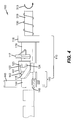
- FIG. 3 shows a top view and Figure 4 shows a perspective view of a first embodiment of the selector assembly 100 of this invention.
- Selector assembly 100 includes a cam member assembly 110, a spring 130 and a selector pin assembly 140 that are each coaxially mounted on the feed roller shaft 319 in this embodiment.
- Cam member assembly 110 includes a cam member 111 which includes a first cam path 112, a second cam path 113, a third cam path 114 (cam paths indicated as dotted lines in Figure 3 ), and a stop position 115; a sleeve 116; a pushing feature 117; and a flange 118.
- Cam member assembly 110 can optionally be made as an integrally formed part, for example by injection molding.
- each cam path is the stop position 115, while the other end of the three cam paths are slots 122, 123 and 124 respectively.
- Spring 130 is positioned toward the end of the feed roller shaft 319 and is adjacent to flange 118 of cam member assembly 110.
- the flange 118 may have an internal recess inside of which one end of spring 130 is retained.
- the other end of spring 130 is positioned against a wall at the right side 306 of printer chassis 300.
- Selector pin assembly 140 On the other side of cam assembly 110, the selector pin assembly 140 is mounted.
- Selector pin assembly 140 which optionally may be made as an integrally formed part (for example, by injection molding), includes selector pin 142 extending radially outwardly from friction mount sleeve 144, and arm(s) 146 also extending outwardly from friction mount sleeve 144.
- Cam member 111 cantilevers over friction mount sleeve 144, such that selector pin 142 is captured within the open area of cam member 111, and extends through it, as seen more clearly in Figure 4 .
- Selector pin 142 is sized to fit into each of slots 122, 123 and 124, as well as into stop position 115.
- friction mount sleeve 144 which functions as a type of clutch mechanism.
- the fit of friction mount sleeve 144 on feed roller shaft 319 is sufficiently close that friction mount sleeve 144 will rotate when feed roller shaft 319 rotates, but it is loose enough that friction mount 144 can be rotated independently of feed roller shaft 319.
- the fit of sleeve 116 of cam assembly 110 is loose enough, or cam assembly 110 is optionally constrained rotationally, so that cam assembly 110 does not rotate significantly when feed roller shaft 319 rotates.
- Friction mount sleeve 144 is constrained translationally along feed roller shaft 319, so that it may not be moved back and forth significantly along the shaft.
- Cam assembly 110 is free to move back and forth along feed roller shaft 319, but is biased toward selector pin assembly 140 by spring 130.
- selector pin assembly 140 (including arm 146) to rotate relative to the feed roller shaft 319. If the carriage 200 is moved to the left in this example, spring 130 pushes cam assembly 110 toward selector pin assembly 140 so that selector pin 142 moves along one of the cam paths 112, 113 or 114, the particular path depending upon whether the feed roller 312 is rotated as carriage 200 moves to the left. If feed roller 312 is not rotated, then selector pin 142 moves parallel to the axis of the feed roller shaft 319 along path 112 into slot 122.
- Different slots may be reached from the intermediate location by the selector pin 142 following different cam paths. While in the present example, the intermediate location is defined by stop position 115 beyond which selector pin 142 can not move, in other embodiments the intermediate location does not need to occur at a stop position.
- arm 146 rotates correspondingly.
- gear engagement / disengagement possibilities that the selector pin assembly 100 of the present invention may enable.
- arm 146 is configured to interact with different gears or gear assemblies, selectively enabling or disabling power transmission from the media feed motor, depending upon its rotational position around feed roller shaft 319.
- a surface of arm 146 may prevent a pivoting gear assembly from rotating into engagement with another gear assembly, while in another rotational position of arm 146, that pivoting gear assembly is free to rotate into engagement with a first gear or a second gear, depending upon the direction of rotation of feed roller shaft 319.
- an arm in one rotational position an arm may push a gear out of engagement with another gear, while in another rotational position, an arm 146 (the same arm, or a different arm, or a different surface of the same arm) may push a gear into engagement with another gear, regardless of direction of rotation of the feed roller shaft.
- a gear that is driven by the media advance motor may be mounted on arm 146 and rotated into or out of engagement with other gears.
- the carriage 200 has enabled the changing of power transmission engagement in this invention, the carriage is free to move away from the selector assembly 100.
- selector assembly 100 of the present invention three separate power transmission engagements are possible (corresponding to selector pin being in either slot 122, 123 or 124), rather than just two.
- there can be even more individually selectable power transmission engagements by designing a cam member 111 having more than three branches of cam paths.
- four different power transmission engagements could be enabled by the selector assembly 100 shown in Figures 3 and 4 .
- a variety of printer functions may be selectively enabled using selector assembly 100.
- a pick function is enabled with selector pin 142 in slot 124
- a printing function is enabled with selector pin 142 in slot 122
- a photo tray movement function is enabled with selector pin 142 in slot 123.
- power from the media advance motor is transmitted to all four of the rollers shown schematically in Figure 2 , i.e. pick roller 320, turn roller 322, feed roller 312, and discharge roller 324 and causes them to rotate in forward direction 313.
- the pick roller 320 advances the top sheet 371 to the turn roller 322, the turn roller 322 advances the sheet to the feed roller 312, and the feed roller advances the sheet to the discharge roller 324 when the motor rotates such that the four rollers rotate in forward direction 313.
- the pick function has a second mode called the deskew mode, which is enabled with selector pin 142 in slot 122, but with the media advance motor rotating in reverse.
- the deskew mode may be useful for certain types of jobs, such as printing photos on 4"x6" photo papers.
- the roller motion in deskew mode is indicated in Figure 5 .
- the gear from the media advance motor that extends through hole 310 is always engaged with feed roller gear 311 and the discharge roller gear (not shown). Thus when the motor rotates in reverse, both the feed roller 312 and the discharge roller 324 rotate in reverse direction (opposite 313).
- the pick roller 320 and the turn roller 322 are each connected to power transmission through pivoting gear assemblies, such that even if the motor turns in reverse, the pick roller 320 and the turn roller 322 continue to move in forward direction 313.
- the pick roller 320 and the turn roller 322 advance the paper toward the feed roller 312, but the feed roller 312 is rotating in reverse and resists forward movement of the paper. If the paper is misoriented such that its leading edge is not parallel with the feed roller 312, the first portion of the leading edge that hits reversely spinning feed roller 312 is slowed down until the rest of the leading edge can catch up, thus deskewing the paper.
- the carriage 200 When deskewing is completed, the carriage 200 is again moved to the right such that the pushing feature 117 is pushed and the selector pin 142 moves to the stop position 115. With the feed roller 312 stationary, the carriage 200 moves to the left, such that the selector pin moves to slot 122 to enable the printing function mode.
- the printing function mode power from the media advance motor is transmitted to forwardly rotate the turn roller 322, the feed roller 312 and the discharge roller 324, but no power is transmitted to the pick roller 320.
- the pick roller 320 disabled, printing media can continue to advance through the printer without the pick roller 320 advancing a next sheet until needed. If the deskew mode of paper advance is being used, then the next sheet cannot be advanced to feed roller 312 until the previous sheet has been discharged, because the deskew mode operates the feed roller 312 and the discharge roller 324 in reverse.
- the pick function forward mode also called the "tailgating mode”
- one sheet can immediately follow the next, with no gap between the two sheets.
- the faster printing throughput tailgating mode is used.
- the tailgating mode begins with the selector pin moved into slot 123 and the paper advance motor rotating all four rollers in the forward direction 313. Once the paper has been advanced to the turn roller 322, the carriage 200 can be moved to the right, pushing the cam assembly 110, thus moving the selector pin 142 to stop position 115.
- the feed roller 312 is stopped.
- selector pin 142 will be released back to slot 122 into the printing position.
- the carriage 200 moves to the right, pushing the cam assembly 110 and releasing it while the feed roller 312 moves forward, so that selector pin 142 moves into slot 124 to enable the pick forward mode for picking the next sheet. Since in this tailgating sequence it is never required to move the feed roller 312 backwards, it is evident that the picking operation can be activated or deactivated at any point during printing. Thus a sheet can be picked immediately after the previous one, with no gaps between the two sheets.
- the timing of switching modes by actuating selector assembly 100 can be adjusted depending upon the length of the sheets of media.
- a third function which can be optionally selected is photo tray movement, for example when selector pin 142 is positioned in slot 123.
- an arm 146 of selector pin assembly 140 causes a gear to engage with a rack (not shown) that can move a photo paper tray back and forth depending on the direction of motor rotation, as in Figures 6 and 7 .
- a paper stack 370 in main paper tray 372 and there is a stack of photo paper 373 in photo paper tray 374.
- the sheets in paper stack 370 are of a larger size (for example, 8.5" x 11") compared to the sheets in paper stack 373 (for example, 4" x 6"), and photo paper tray 374 is not as long as main paper tray 372.
- the photo paper tray 374 has been moved to its forward position, for example by rotating the paper advance motor in a first direction such that the gear and the rack cause the tray to move forward. In this position, the pick roller 320 is able to contact the top sheet in paper stack 370 in the main tray 372. Also in the forward position of the photo paper tray 374, additional photo paper 373 may be loaded.
- the photo tray 374 has been moved along direction 302 to its printing position, for example by rotating the paper advance motor in a second direction that is opposite the first direction. In the printing position of the photo paper tray 374, the pickup roller 320 is able to contact the top sheet in photo paper stack 373. In some embodiments the pickup roller is mounted on a pivotable pick arm which is able to be moved up or down to rest on the top sheet of whichever tray is beneath it.
- selector assembly 100 While the embodiments above described a particular group of functions that may be enabled by selector assembly 100, various other functions may be enabled in other embodiments. These may include other functions that require motion, such as the maintenance functions of capping, wiping or pumping.
- Selector assembly 100 may be made in other ways than the coaxially mounted cam assembly 110, spring 130 and selector pin assembly 140.
- a second embodiment of a selector assembly is shown in Figure 8 .
- the functions of the cam assembly 110 and the spring 130 are incorporated together as leaf spring cam assembly 150.
- Leaf spring cam assembly 150 consists of bent thin strip of metal or plastic, for example, and includes a cam member portion 151 with slots 152, 153 and 154 and a stop position 155; a pushing portion 157; and a mounting portion 158 with a hole 159.
- Leaf spring cam assembly 150 may be made by standard metal or plastic forming processes.
- Leaf spring cam assembly 150 operates in much the same way as was described above for the cam assembly 110, and cam member portion 151 has cam paths similar to those in cam member 111.
- a selector pin assembly 140 of the same or similar design to that described above operates in conjunction with leaf spring cam assembly 150.
- Feed roller shaft 319 passes through hole 159 in mounting portion 158.
- Cam member portion 151 cantilevers over selector pin assembly 140 such that selector pin 142 is captured within the open slotted region.
- the mounting portion 158 is constrained translationally on feed roller shaft 319, so that in its normal position, cam member portion 151 is located such that selector pin 142 will be positioned in one of the slots 152, 153 or 154.
- the carriage 200 pushes the pushing portion 157, causing the leaf spring cam assembly to bend, and allowing the cam member portion 151 to move parallel to the axis of the feed roller shaft 319 in a direction that locates the stop position 155 at the selector pin 142.
- the restoring force of the leaf spring cam assembly 150 causes it to assume its normal configuration, and selector pin 142 will be located in slot 152, 153 or 154, depending on whether and which way the feed roller 312 turned as the carriage 200 released the pushing portion 157.
Description
- The invention relates generally to the field of inkjet printers, and in particular to a mechanical device that and a corresponding method enable selective engagement of one or more of a plurality of operational modes of the printer, where each mode is driven by the same motor.
- An inkjet printing system typically includes one or more printheads and their corresponding ink supplies. Each printhead includes an ink inlet that is connected to its ink supply and an array of drop ejectors, each ejector consisting of an ink chamber, an ejecting actuator and an orifice through which droplets of ink are ejected. The ejecting actuator may be one of various types, including a heater that vaporizes some of the ink in the chamber in order to propel a droplet out of the orifice, or a piezoelectric device which changes the wall geometry of the chamber in order to generate a pressure wave that ejects a droplet. The droplets are typically directed toward paper or other print medium (sometimes generically referred to as paper herein) in order to produce an image according to image data that is converted into electronic firing pulses for the drop ejectors as the print medium is moved relative to the printhead.
- Motion of the print medium relative to the printhead may consist of keeping the printhead stationary and advancing the print medium past the printhead while the drops are ejected. This architecture is appropriate if the nozzle array on the printhead can address the entire region of interest across the width of the print medium. Such printheads are sometimes called pagewidth printheads. A second type of printer architecture is the carriage printer, where the printhead nozzle array is somewhat smaller than the extent of the region of interest for printing on the print medium and the printhead is mounted on a carriage. In a carriage printer, the print medium is advanced a given distance along a print medium advance direction and then stopped. While the print medium is stopped, the printhead carriage is moved in a direction that is substantially perpendicular to the print medium advance direction as the drops are ejected from the nozzles. After the carriage has printed a swath of the image while traversing the print medium, the print medium is advanced, the carriage direction of motion is reversed, and the image is formed swath by swath. In order to accomplish the motions necessary for printing in a carriage printer, there are typically at least two motors - the motor for print medium advance, and the motor for carriage motion. The examples described in the present invention relate to a carriage printer architecture.
- As carriage printer technology matures, there is a need to offer more functions and at lower cost. While previous printers may have dedicated a separate motor (in addition to the motor for paper advance and the motor for carriage motion) to drive an additional function, offering the function without the need for an additional motor is desirable.
- It is known in the prior art to use the power of the paper advance motor to operate the various functions of the maintenance station in an inkjet printer.
US Patent Nos. 6,846,060 and7,225,697 , for example, describe power transmission mechanisms that are selectively engaged or disengaged depending on whether or not the carriage is parked at the maintenance station. If the carriage is parked at the maintenance station, a feature on the carriage enables the power transmission mechanism to be engaged. By this means, the maintenance station functions including wiping and capping may be powered by the paper advance motor. When the carriage moves away from the maintenance station, the feature on the carriage no longer enables the power transmission to be engaged for maintenance operations, so that the paper advance motor is used for moving paper through the printer. - For some modes of printing, it is necessary to operate different paper advancing rollers at different times or in different directions. In such a case, a mechanism such as those in '060 and '697 which only allows engagement when the carriage and printhead are parked at the maintenance station is not sufficient.
-
US 2004/196327 - A1 discloses a printer with a selector pin and a cam member. - There is a need, therefore, for a selector mechanism that can operate in different selection positions even after the carriage has moved away, and that can selectively engage one or more of a plurality of functions, driven selectively by a single motor.
- According to one feature of the present invention, a printer includes a selector pin and a cam member. Such a printer is disclosed in claim 1.
- According to another feature of the present invention, a method of driving multiple printer functions using the same motor is disclosed in claim 11.
- In the detailed description of the preferred embodiments of the invention presented below, reference is made to the accompanying drawings, in which:
-
Figure 1 is a perspective illustration of a printer including an embodiment of the present invention; -
Figure 2 is a schematic side view showing paper being advanced through the printer; -
Figure 3 is a top view of an embodiment of the selector assembly of the present invention; -
Figure 4 is a perspective view of an embodiment of the selector assembly of the present invention; -
Figure 5 is a schematic side view showing paper being advanced in a deskew mode; -
Figure 6 is a schematic side view showing a photo paper tray in its forward position; -
Figure 7 is a schematic side view showing a photo paper tray in its printing position; and -
Figure 8 is a perspective view of a second embodiment of the cam member assembly. - The present description will be directed in particular to elements forming part of, or cooperating more directly with, apparatus in accordance with the present invention. It is to be understood that elements not specifically shown or described may take various forms well known to those skilled in the art.
- In the following description of preferred embodiments, directional terminology such as front, rear, left, right, top, bottom, etc. is used with reference to the orientation of the figure being described or to the orientation of a component when it is located in its normal operating position in the example being described. Because components of the embodiments of the present invention can be positioned in a number of different orientations, the directional terminology is used for purposes of illustration and is in no way limiting.
-
Figure 1 shows a portion of a carriage printer that includes an embodiment of the present invention.Printer chassis 300 has aprint region 303 across whichcarriage 200 is moved back and forth between theright side 306 and theleft side 307 ofprinter chassis 300 while printing.Carriage motor 380 movesbelt 384 to movecarriage 200 back and forth alongcarriage guide rail 382.Printhead chassis 250 is mounted incarriage 200, andink supplies printhead chassis 250. Paper, or other print media is loaded along paperload entry direction 302 toward thefront 308 ofprinter chassis 300. A variety of rollers are used to advance the medium through the printer, as shown schematically in the side view ofFigure 2 . - In
Figure 2 , apickup roller 320 moves thetop sheet 371 of astack 370 of paper or other media in the direction ofarrow 302. Aturn roller 322 toward the rear 309 of theprinter chassis 300 acts to move the paper around a C-shaped path (in cooperation with a curved rear wall surface) so that the paper continues to advance alongdirection arrow 304 from the rear 309 of the printer. The paper is then moved byfeed roller 312 and idler roller(s) 323 to advance acrossprint region 303, and from there to adischarge roller 324 and star wheel(s) 325 so that printed paper exits alongdirection 304.Feed roller 312 includes afeed roller shaft 319 along its axis, andfeed roller gear 311 is mounted on thefeed roller shaft 319.Feed roller 312 may consist of a separate roller mounted onfeed roller shaft 319, or may consist of a thin high friction coating onfeed roller shaft 319. - Referring back to
Figure 1 ,selector assembly 100 is mounted in association withfeed roller shaft 319, and is nearfeed roller gear 311. Themotor 394 that powers the paper advance rollers is shown schematically inFigure 1 .Hole 310 at theright side 306 of theprinter chassis 300 is where the motor gear (not shown) protrudes through in order to engagefeed roller gear 311, as well as the gear for the discharge roller (not shown). For normal paper pick-up and feeding, it is desired that all rollers rotate inforward direction 313. Toward theleft side 307 in the example ofFigure 1 (and near the end of thefeed roller 312 that is opposite the end wherefeed roller gear 311 is mounted) is themaintenance station 330. Toward the rear 309 of the printer in this example is located theelectronics board 390, which containscable connectors 392 for communicating via cables (not shown) to theprinthead carriage 200 and from there to the printhead. Also on the electronics board are typically mounted motor controllers for thecarriage motor 380 and for the paper advance motor, a processor and/or other control electronics for controlling the printing process, and an optional connector for a cable to a host computer. -
Figure 3 shows a top view andFigure 4 shows a perspective view of a first embodiment of theselector assembly 100 of this invention.Selector assembly 100 includes acam member assembly 110, aspring 130 and aselector pin assembly 140 that are each coaxially mounted on thefeed roller shaft 319 in this embodiment.Cam member assembly 110 includes acam member 111 which includes afirst cam path 112, asecond cam path 113, a third cam path 114 (cam paths indicated as dotted lines inFigure 3 ), and astop position 115; asleeve 116; a pushingfeature 117; and aflange 118.Cam member assembly 110 can optionally be made as an integrally formed part, for example by injection molding. One end of each cam path is thestop position 115, while the other end of the three cam paths areslots Spring 130 is positioned toward the end of thefeed roller shaft 319 and is adjacent to flange 118 ofcam member assembly 110. Optionally theflange 118 may have an internal recess inside of which one end ofspring 130 is retained. The other end ofspring 130 is positioned against a wall at theright side 306 ofprinter chassis 300. - On the other side of
cam assembly 110, theselector pin assembly 140 is mounted.Selector pin assembly 140, which optionally may be made as an integrally formed part (for example, by injection molding), includesselector pin 142 extending radially outwardly fromfriction mount sleeve 144, and arm(s) 146 also extending outwardly fromfriction mount sleeve 144.Cam member 111 cantilevers overfriction mount sleeve 144, such thatselector pin 142 is captured within the open area ofcam member 111, and extends through it, as seen more clearly inFigure 4 .Selector pin 142 is sized to fit into each ofslots stop position 115. - Also shown in
Figure 4 areslots 148 infriction mount sleeve 144, which functions as a type of clutch mechanism. The fit offriction mount sleeve 144 onfeed roller shaft 319 is sufficiently close thatfriction mount sleeve 144 will rotate whenfeed roller shaft 319 rotates, but it is loose enough thatfriction mount 144 can be rotated independently offeed roller shaft 319. The fit ofsleeve 116 ofcam assembly 110 is loose enough, orcam assembly 110 is optionally constrained rotationally, so thatcam assembly 110 does not rotate significantly whenfeed roller shaft 319 rotates.Friction mount sleeve 144 is constrained translationally alongfeed roller shaft 319, so that it may not be moved back and forth significantly along the shaft.Cam assembly 110 is free to move back and forth alongfeed roller shaft 319, but is biased towardselector pin assembly 140 byspring 130. - Next the operation of the
selector assembly 110 will be explained.Spring 130 tends to pushcam assembly 110 towardselector pin assembly 140, so thatselector pin 142 is normally located in one of the threeslots carriage 200 is moved sufficiently toward theright side 306 ofprinter chassis 300 in this example, a feature (not shown) oncarriage 200hits pushing feature 117, causingcam assembly 110 to move toward the right and compressspring 130. As this happens, theselector pin 142 will move relative to thecam member 111 along thecam path position 115 from the slot (122, 123 or 124 respectively) that it had been in. If the pin had been in slotmiddle slot 122, no rotation ofselector pin assembly 140 occurs during this operation. However, if the pin had been in eitherslot pin 142 and the outside cam surfaces ofcam member 111 will cause selector pin assembly 140 (including arm 146) to rotate relative to thefeed roller shaft 319. If thecarriage 200 is moved to the left in this example,spring 130 pushescam assembly 110 towardselector pin assembly 140 so thatselector pin 142 moves along one of thecam paths feed roller 312 is rotated ascarriage 200 moves to the left. Iffeed roller 312 is not rotated, thenselector pin 142 moves parallel to the axis of thefeed roller shaft 319 alongpath 112 intoslot 122. If the media advance motor turns feedroller 312 inforward rotation direction 313,friction mount sleeve 144 will causeselector pin assembly 140 to rotate indirection 313, whilecam assembly 110 does not rotate, so thatselector pin 142 moves alongcam path 114 to slot 124. If the media advance motor turns feedroller 312 in reverse,friction mount sleeve 144 will causeselector pin assembly 140 to rotate in reverse, whilecam assembly 110 does not rotate, so thatselector pin 142 moves alongcam path 113 to slot 123.Selector pin 142 is held in whichever slot it was moved to untilcarriage 200 is moved back at some later time and pushes the pushingfeature 117 so that the selector pin is moved to its location at thestop position 115, and can then be moved to a different slot if desired. Different slots may be reached from the intermediate location by theselector pin 142 following different cam paths. While in the present example, the intermediate location is defined bystop position 115 beyond whichselector pin 142 can not move, in other embodiments the intermediate location does not need to occur at a stop position. - As
selector pin assembly 140 is rotated and held in different positions corresponding toslots arm 146 rotates correspondingly. There are a variety of possible gear engagement / disengagement possibilities that theselector pin assembly 100 of the present invention may enable. In one embodiment of this invention,arm 146 is configured to interact with different gears or gear assemblies, selectively enabling or disabling power transmission from the media feed motor, depending upon its rotational position aroundfeed roller shaft 319. For example, in one rotational position, a surface ofarm 146 may prevent a pivoting gear assembly from rotating into engagement with another gear assembly, while in another rotational position ofarm 146, that pivoting gear assembly is free to rotate into engagement with a first gear or a second gear, depending upon the direction of rotation offeed roller shaft 319. In another embodiment, in one rotational position an arm may push a gear out of engagement with another gear, while in another rotational position, an arm 146 (the same arm, or a different arm, or a different surface of the same arm) may push a gear into engagement with another gear, regardless of direction of rotation of the feed roller shaft. In still another embodiment, a gear that is driven by the media advance motor may be mounted onarm 146 and rotated into or out of engagement with other gears. - Once the
carriage 200 has enabled the changing of power transmission engagement in this invention, the carriage is free to move away from theselector assembly 100. This means that different operational modes of printing can be selectively enabled byselector assembly 100 of the present invention. Furthermore, in this embodiment, three separate power transmission engagements are possible (corresponding to selector pin being in eitherslot cam member 111 having more than three branches of cam paths. In fact, it is also possible to have a translational motion of theselector pin assembly 140 alongfeed roller shaft 319, so thatarm 146 enables a different gear engagement whenselector pin 142 is in thestop position 115 than when the selector pin is inslot 122. In such an embodiment, four different power transmission engagements could be enabled by theselector assembly 100 shown inFigures 3 and4 . - A variety of printer functions may be selectively enabled using
selector assembly 100. In one embodiment of this invention, a pick function is enabled withselector pin 142 inslot 124, a printing function is enabled withselector pin 142 inslot 122, and a photo tray movement function is enabled withselector pin 142 inslot 123. In the pick function forward mode, power from the media advance motor is transmitted to all four of the rollers shown schematically inFigure 2 , i.e.pick roller 320,turn roller 322, feedroller 312, anddischarge roller 324 and causes them to rotate inforward direction 313. Thus, thepick roller 320 advances thetop sheet 371 to theturn roller 322, theturn roller 322 advances the sheet to thefeed roller 312, and the feed roller advances the sheet to thedischarge roller 324 when the motor rotates such that the four rollers rotate inforward direction 313. - The pick function has a second mode called the deskew mode, which is enabled with
selector pin 142 inslot 122, but with the media advance motor rotating in reverse. The deskew mode may be useful for certain types of jobs, such as printing photos on 4"x6" photo papers. The roller motion in deskew mode is indicated inFigure 5 . With reference toFigure 1 , the gear from the media advance motor that extends throughhole 310 is always engaged withfeed roller gear 311 and the discharge roller gear (not shown). Thus when the motor rotates in reverse, both thefeed roller 312 and thedischarge roller 324 rotate in reverse direction (opposite 313). However, in an embodiment of this invention, thepick roller 320 and theturn roller 322 are each connected to power transmission through pivoting gear assemblies, such that even if the motor turns in reverse, thepick roller 320 and theturn roller 322 continue to move inforward direction 313. Thus, in the deskew mode, thepick roller 320 and theturn roller 322 advance the paper toward thefeed roller 312, but thefeed roller 312 is rotating in reverse and resists forward movement of the paper. If the paper is misoriented such that its leading edge is not parallel with thefeed roller 312, the first portion of the leading edge that hits reversely spinningfeed roller 312 is slowed down until the rest of the leading edge can catch up, thus deskewing the paper. When deskewing is completed, thecarriage 200 is again moved to the right such that the pushingfeature 117 is pushed and theselector pin 142 moves to thestop position 115. With thefeed roller 312 stationary, thecarriage 200 moves to the left, such that the selector pin moves to slot 122 to enable the printing function mode. - In the printing function mode, power from the media advance motor is transmitted to forwardly rotate the
turn roller 322, thefeed roller 312 and thedischarge roller 324, but no power is transmitted to thepick roller 320. Thus in the printing mode, with thepick roller 320 disabled, printing media can continue to advance through the printer without thepick roller 320 advancing a next sheet until needed. If the deskew mode of paper advance is being used, then the next sheet cannot be advanced to feedroller 312 until the previous sheet has been discharged, because the deskew mode operates thefeed roller 312 and thedischarge roller 324 in reverse. - However, in the pick function forward mode (also called the "tailgating mode") described above, one sheet can immediately follow the next, with no gap between the two sheets. Thus when deskew is not required, the faster printing throughput tailgating mode is used. The tailgating mode begins with the selector pin moved into
slot 123 and the paper advance motor rotating all four rollers in theforward direction 313. Once the paper has been advanced to theturn roller 322, thecarriage 200 can be moved to the right, pushing thecam assembly 110, thus moving theselector pin 142 to stopposition 115. During carriage motion (e.g. during printing of a swath) thefeed roller 312 is stopped. If thefeed roller 312 remains stopped as the carriage moves back to the left,selector pin 142 will be released back toslot 122 into the printing position. When it is desired to pick the next sheet, thecarriage 200 moves to the right, pushing thecam assembly 110 and releasing it while thefeed roller 312 moves forward, so thatselector pin 142 moves intoslot 124 to enable the pick forward mode for picking the next sheet. Since in this tailgating sequence it is never required to move thefeed roller 312 backwards, it is evident that the picking operation can be activated or deactivated at any point during printing. Thus a sheet can be picked immediately after the previous one, with no gaps between the two sheets. The timing of switching modes by actuatingselector assembly 100 can be adjusted depending upon the length of the sheets of media. - A third function which can be optionally selected is photo tray movement, for example when
selector pin 142 is positioned inslot 123. In one embodiment, in this position anarm 146 ofselector pin assembly 140 causes a gear to engage with a rack (not shown) that can move a photo paper tray back and forth depending on the direction of motor rotation, as inFigures 6 and7 . In both figures there is apaper stack 370 inmain paper tray 372 and there is a stack ofphoto paper 373 inphoto paper tray 374. The sheets inpaper stack 370 are of a larger size (for example, 8.5" x 11") compared to the sheets in paper stack 373 (for example, 4" x 6"), andphoto paper tray 374 is not as long asmain paper tray 372. InFigure 6 , thephoto paper tray 374 has been moved to its forward position, for example by rotating the paper advance motor in a first direction such that the gear and the rack cause the tray to move forward. In this position, thepick roller 320 is able to contact the top sheet inpaper stack 370 in themain tray 372. Also in the forward position of thephoto paper tray 374,additional photo paper 373 may be loaded. InFigure 7 , thephoto tray 374 has been moved alongdirection 302 to its printing position, for example by rotating the paper advance motor in a second direction that is opposite the first direction. In the printing position of thephoto paper tray 374, thepickup roller 320 is able to contact the top sheet inphoto paper stack 373. In some embodiments the pickup roller is mounted on a pivotable pick arm which is able to be moved up or down to rest on the top sheet of whichever tray is beneath it. - While the embodiments above described a particular group of functions that may be enabled by
selector assembly 100, various other functions may be enabled in other embodiments. These may include other functions that require motion, such as the maintenance functions of capping, wiping or pumping. -
Selector assembly 100 may be made in other ways than the coaxially mountedcam assembly 110,spring 130 andselector pin assembly 140. A second embodiment of a selector assembly is shown inFigure 8 . In this second embodiment, the functions of thecam assembly 110 and thespring 130 are incorporated together as leafspring cam assembly 150. Leafspring cam assembly 150 consists of bent thin strip of metal or plastic, for example, and includes acam member portion 151 withslots stop position 155; a pushingportion 157; and a mountingportion 158 with ahole 159. Leafspring cam assembly 150 may be made by standard metal or plastic forming processes. Leafspring cam assembly 150 operates in much the same way as was described above for thecam assembly 110, andcam member portion 151 has cam paths similar to those incam member 111. Aselector pin assembly 140 of the same or similar design to that described above operates in conjunction with leafspring cam assembly 150.Feed roller shaft 319 passes throughhole 159 in mountingportion 158.Cam member portion 151 cantilevers overselector pin assembly 140 such thatselector pin 142 is captured within the open slotted region. The mountingportion 158 is constrained translationally onfeed roller shaft 319, so that in its normal position,cam member portion 151 is located such thatselector pin 142 will be positioned in one of theslots carriage 200 pushes the pushingportion 157, causing the leaf spring cam assembly to bend, and allowing thecam member portion 151 to move parallel to the axis of thefeed roller shaft 319 in a direction that locates thestop position 155 at theselector pin 142. When thecarriage 200 moves away, the restoring force of the leafspring cam assembly 150 causes it to assume its normal configuration, andselector pin 142 will be located inslot feed roller 312 turned as thecarriage 200 released the pushingportion 157. -
- 100
- Selector assembly
- 110
- Cam member assembly
- 111
- Cam member
- 112
- First cam path
- 113
- Second cam path
- 114
- Third cam path
- 115
- Stop position
- 116
- Sleeve
- 117
- Pushing feature
- 118
- Flange
- 122
- First slot
- 123
- Second slot
- 124
- Third slot
- 130
- Spring
- 140
- Selector pin assembly
- 142
- Selector pin
- 144
- Friction mount sleeve
- 146
- Arm
- 148
- Friction mount slots
- 150
- Leaf spring cam assembly
- 151
- Cam member portion
- 152
- First slot
- 153
- Second slot
- 154
- Third slot
- 155
- Stop position
- 157
- Pushing portion
- 158
- Mounting portion
- 159
- Hole
- 200
- Carriage
- 250
- Printhead chassis
- 262
- Multichamber ink supply
- 264
- Single chamber ink supply
- 300
- Printer chassis
- 302
- Paper load entry
- 303
- Print region
- 304
- Paper exit
- 306
- Right side of printer chassis
- 307
- Left side of printer chassis
- 308
- Front of printer chassis
- 309
- Rear of printer chassis
- 310
- Hole for paper advance motor drive gear
- 311
- Feed roller gear
- 312
- Feed roller
- 313
- Forward rotation of feed roller
- 319
- Feed roller shaft
- 320
- Pickup roller
- 322
- Turn roller
- 323
- Idler roller
- 324
- Discharge roller
- 325
- Star wheel
- 330
- Maintenance station
- 370
- Stack of media
- 371
- Top sheet
- 372
- Main paper tray
- 373
- Photo paper stack
- 374
- Photo paper tray
- 380
- Carriage motor
- 382
- Carriage rail
- 384
- Belt
- 390
- Printer electronics board
- 392
- Cable connectors
Claims (14)
- A printer comprising:a selector pin (142), anda cam member (111) including a plurality of paths (112,113,114), each path corresponding to a printer function, the cam member (111) and the selector pin (142) being configured to provide relative movement of the selector pin (142) through the plurality of paths, the location of the selector pin (142) in one of the plurality of paths (112,113,114) enabling the corresponding printer function; wherein, the plurality of paths comprise a shared stop position (115) for the selector pin, the stop position being disposed at one end of the plurality of paths.
- The printer of claim 1, further comprising:a media feed roller (312), anda motor (394) connected to the media feed roller, the media feed roller (312) being driven by the motor, the selector pin and the cam member being positioned about the media feed roller, wherein relative movement of the selector pin through the plurality of paths of the cam member is accomplished when the media feed roller is driven by the motor.
- The printer of claim 2, further comprising:a clutch mechanism, wherein the selector pin (142) is associated with the media feed roller (312) through the clutch mechanism.
- The printer of claim 2, the media feed roller (312) having an axis of rotation, further comprising:a printhead carriage (200) moveable in a direction parallel to the axis of rotation of the media feed roller, the cam member (111) being spring loaded along the axis of the media feed roller and engageable with the printhead carriage, wherein engagement of the printhead carriage with the cam member moves the cam member along the axis of rotation of the feed roller to cause the selector pin to move from one of the plurality of paths to an intermediate location of the cam member which permits movement of the selector pin to another of the plurality of paths of the cam member.
- The printer of claim 4, wherein the intermediate location of the cam member includes a stop position for the selector pin.
- The printer of claim 4, wherein the intermediate position is located at the intersection of the plurality of paths.
- The printer of claim 1, further comprising:a media feed roller (312) including a shaf (314), anda printhead carriage (200) moveable in a direction parallel to the shaft of the media feed roller, the cam member being spring loaded along the shaft of the media feed roller and engageable with the printhead carriage, wherein engagement and disengagement of the printhead carriage with the cam member moves the cam member to cause the selector pin to move from one of the plurality of paths to another of the plurality of paths.
- The printer of claim 7, wherein the cam member (111) being spring loaded along the shaft of the media feed roller includes one of (a) the cam member (111) being a portion of a leaf spring and (b) the cam member (111) and a compression spring both being mounted along the shaft of the media feed roller.
- The printer of claim 1, wherein the plurality of paths includes three paths (112,113,114).
- The printer of claim 1, further comprising:an arm (146) connected to the selector pin (142), wherein movement of the selector pin through the plurality of paths (112,113,114) changes the position of the arm to enable corresponding printer function.
- A method of driving multiple printer functions using the same motor comprising:providing a motor (394),providing a selector pin (142);providing a cam member assembly (110) including a cam member (111) including a plurality of paths (112,113,114) each path including a shared stop position for the selector pin, each path corresponding to a printer function; andrelatively moving the cam member and the selector pin through the plurality of paths to selectively permit the motor to drive the corresponding printer function.
- The method of claim 11, the motor being a first motor, the method further comprising:providing a printhead carriage (200),providing a second motor (380) that drives the printhead carriage to engage the cam member assembly; wherein engaging the printhead carriage with the cam member assembly moves the cam member to cause the selector pin to move from one of the plurality of paths to an intermediate location of the cam member which permits movement of the selector pin to another of the plurality of paths of the cam member.
- The method of claim 11, further comprising:providing a first roller and a second roller, the multiple printer functions including a first printer function comprising rotating the first roller in a first direction without rotating the second roller, and a second printer function comprising rotating the first roller and the second roller in the first direction, wherein relatively moving the cam member (111) and the selector pin (142) causes a change between the first printer function and the second printer function without rotating the first roller in a direction that is opposite the first direction.
- The method of claim 11, wherein two of the printer functions cause media movement.
Applications Claiming Priority (2)
| Application Number | Priority Date | Filing Date | Title |
|---|---|---|---|
| US11/969,277 US8104885B2 (en) | 2008-01-04 | 2008-01-04 | Selector for engagement of printer functions |
| PCT/US2008/014016 WO2009088449A1 (en) | 2008-01-04 | 2008-12-22 | Selector for engagement of printer functions |
Publications (2)
| Publication Number | Publication Date |
|---|---|
| EP2231412A1 EP2231412A1 (en) | 2010-09-29 |
| EP2231412B1 true EP2231412B1 (en) | 2012-12-12 |
Family
ID=40532491
Family Applications (1)
| Application Number | Title | Priority Date | Filing Date |
|---|---|---|---|
| EP08870527A Active EP2231412B1 (en) | 2008-01-04 | 2008-12-22 | Selector for engagement of printer functions |
Country Status (4)
| Country | Link |
|---|---|
| US (1) | US8104885B2 (en) |
| EP (1) | EP2231412B1 (en) |
| JP (1) | JP2011509196A (en) |
| WO (1) | WO2009088449A1 (en) |
Families Citing this family (16)
| Publication number | Priority date | Publication date | Assignee | Title |
|---|---|---|---|---|
| US8376487B2 (en) | 2009-11-09 | 2013-02-19 | Eastman Kodak Company | Air extraction printer |
| US8235514B2 (en) | 2009-11-09 | 2012-08-07 | Eastman Kodak Company | Air extraction device for inkjet printhead |
| US8215631B2 (en) * | 2010-08-30 | 2012-07-10 | Eastman Kodak Company | Pick roller retraction in a carriage printer |
| US8469502B2 (en) | 2011-04-28 | 2013-06-25 | Eastman Kodak Company | Air extraction piston device for inkjet printhead |
| US8201817B1 (en) | 2011-04-28 | 2012-06-19 | Eastman Kodak Company | Pick roller with delay clutch |
| US8469501B2 (en) | 2011-04-28 | 2013-06-25 | Eastman Kodak Company | Air extraction method for inkjet printhead |
| EP2737392B1 (en) | 2011-07-29 | 2021-05-26 | Hewlett-Packard Development Company, L.P. | Printer |
| US8480206B2 (en) | 2011-08-31 | 2013-07-09 | Eastman Kodak Company | Carriage printer with bubble dislodging and removal |
| US8474945B2 (en) | 2011-08-31 | 2013-07-02 | Eastman Kodak Company | Dislodging and removing bubbles from inkjet printhead |
| WO2013106089A1 (en) | 2011-08-31 | 2013-07-18 | Eastman Kodak Company | Reciprocating carriage printer with air bubble dislodging and removal |
| US8573585B1 (en) | 2012-05-30 | 2013-11-05 | Hewlett-Packard Development Company, L.P. | Media handling system |
| TW201350343A (en) * | 2012-06-13 | 2013-12-16 | Hon Hai Prec Ind Co Ltd | Transmitting apparatus for printer |
| US8915495B2 (en) | 2012-08-21 | 2014-12-23 | Hewlett-Packard Development Company, L.P. | Media transport |
| WO2017123200A1 (en) * | 2016-01-11 | 2017-07-20 | Hewlett-Packard Development Company, L.P. | Selectable drive system |
| CN108290423B (en) | 2016-01-15 | 2020-01-14 | 惠普发展公司有限责任合伙企业 | Selectable drive printing apparatus |
| US10527131B2 (en) | 2016-01-21 | 2020-01-07 | Hewlett-Packard Development Company, L.P. | Selectable drive printing device |
Family Cites Families (7)
| Publication number | Priority date | Publication date | Assignee | Title |
|---|---|---|---|---|
| JPS63184754U (en) * | 1987-05-20 | 1988-11-28 | ||
| KR0124528Y1 (en) * | 1995-10-17 | 1999-03-30 | 김광호 | Sheet transferring device for a printer |
| US6334725B1 (en) * | 1999-08-20 | 2002-01-01 | Canon Kabushiki Kaisha | Drive transmitting apparatus and image forming apparatus |
| JP4126900B2 (en) | 2001-11-26 | 2008-07-30 | セイコーエプソン株式会社 | Inkjet printer head maintenance mechanism |
| US6890055B2 (en) | 2002-05-31 | 2005-05-10 | Hewlett-Packard Development Company, L.P. | Power transmission arrangement |
| US6846060B2 (en) | 2003-04-22 | 2005-01-25 | Hewlett-Packard Development Company | Printhead servicing mechanism and method |
| JP4566106B2 (en) | 2005-09-30 | 2010-10-20 | ブラザー工業株式会社 | Image recording device |
-
2008
- 2008-01-04 US US11/969,277 patent/US8104885B2/en not_active Expired - Fee Related
- 2008-12-22 EP EP08870527A patent/EP2231412B1/en active Active
- 2008-12-22 WO PCT/US2008/014016 patent/WO2009088449A1/en active Application Filing
- 2008-12-22 JP JP2010541432A patent/JP2011509196A/en active Pending
Also Published As
| Publication number | Publication date |
|---|---|
| WO2009088449A1 (en) | 2009-07-16 |
| EP2231412A1 (en) | 2010-09-29 |
| US20090174733A1 (en) | 2009-07-09 |
| JP2011509196A (en) | 2011-03-24 |
| US8104885B2 (en) | 2012-01-31 |
Similar Documents
| Publication | Publication Date | Title |
|---|---|---|
| EP2231412B1 (en) | Selector for engagement of printer functions | |
| EP2231411B1 (en) | Full function maintenance station | |
| US20010017635A1 (en) | Image forming apparatus | |
| EP0422794B1 (en) | Printer with carriage-actuated clutch and paper-feed mechanism | |
| JP2008168620A (en) | Inkjet recorder and inkjet recording method | |
| US8201817B1 (en) | Pick roller with delay clutch | |
| US8328183B2 (en) | Media stopper for a printing system | |
| US8302957B2 (en) | Motor inside pick-up roller | |
| US8215631B2 (en) | Pick roller retraction in a carriage printer | |
| EP1800868B1 (en) | Inkjet image forming apparatus including cap member | |
| US8215751B2 (en) | Carriage with improved print cartridge mounting reliability | |
| US20120274019A1 (en) | Method of advancing successive sheets of media | |
| US8215633B2 (en) | Media stopper method for a printing system | |
| US8807738B2 (en) | Carriage activated pump for inkjet printer | |
| JP2000094659A (en) | Recorder and control method thereof | |
| JP2003080720A (en) | Ink jet recorder, blade cleaning device and blade cleaner | |
| US8215632B2 (en) | Pick roller retraction method in a carriage printer | |
| KR100492086B1 (en) | Paper feeding device for printer | |
| US20020084161A1 (en) | Dual gear train for ink jet printer | |
| JP3762154B2 (en) | Drive transmission device and image forming apparatus | |
| JPH06270408A (en) | Ink jet recording apparatus | |
| JP2006056638A (en) | Ink jet recording device | |
| US20130258019A1 (en) | Pump disposed around output shaft of inkjet printer | |
| JPH05135753A (en) | Battery pack fitting means and recording device with this means | |
| JP2007254121A (en) | Recording device |
Legal Events
| Date | Code | Title | Description |
|---|---|---|---|
| PUAI | Public reference made under article 153(3) epc to a published international application that has entered the european phase |
Free format text: ORIGINAL CODE: 0009012 |
|
| 17P | Request for examination filed |
Effective date: 20100709 |
|
| AK | Designated contracting states |
Kind code of ref document: A1 Designated state(s): AT BE BG CH CY CZ DE DK EE ES FI FR GB GR HR HU IE IS IT LI LT LU LV MC MT NL NO PL PT RO SE SI SK TR |
|
| AX | Request for extension of the european patent |
Extension state: AL BA MK RS |
|
| DAX | Request for extension of the european patent (deleted) | ||
| GRAC | Information related to communication of intention to grant a patent modified |
Free format text: ORIGINAL CODE: EPIDOSCIGR1 |
|
| GRAP | Despatch of communication of intention to grant a patent |
Free format text: ORIGINAL CODE: EPIDOSNIGR1 |
|
| GRAS | Grant fee paid |
Free format text: ORIGINAL CODE: EPIDOSNIGR3 |
|
| GRAA | (expected) grant |
Free format text: ORIGINAL CODE: 0009210 |
|
| AK | Designated contracting states |
Kind code of ref document: B1 Designated state(s): AT BE BG CH CY CZ DE DK EE ES FI FR GB GR HR HU IE IS IT LI LT LU LV MC MT NL NO PL PT RO SE SI SK TR |
|
| REG | Reference to a national code |
Ref country code: GB Ref legal event code: FG4D |
|
| REG | Reference to a national code |
Ref country code: CH Ref legal event code: EP |
|
| REG | Reference to a national code |
Ref country code: AT Ref legal event code: REF Ref document number: 588138 Country of ref document: AT Kind code of ref document: T Effective date: 20121215 |
|
| REG | Reference to a national code |
Ref country code: IE Ref legal event code: FG4D |
|
| REG | Reference to a national code |
Ref country code: DE Ref legal event code: R096 Ref document number: 602008020872 Country of ref document: DE Effective date: 20130207 |
|
| REG | Reference to a national code |
Ref country code: NL Ref legal event code: T3 |
|
| PG25 | Lapsed in a contracting state [announced via postgrant information from national office to epo] |
Ref country code: LT Free format text: LAPSE BECAUSE OF FAILURE TO SUBMIT A TRANSLATION OF THE DESCRIPTION OR TO PAY THE FEE WITHIN THE PRESCRIBED TIME-LIMIT Effective date: 20121212 Ref country code: SE Free format text: LAPSE BECAUSE OF FAILURE TO SUBMIT A TRANSLATION OF THE DESCRIPTION OR TO PAY THE FEE WITHIN THE PRESCRIBED TIME-LIMIT Effective date: 20121212 Ref country code: NO Free format text: LAPSE BECAUSE OF FAILURE TO SUBMIT A TRANSLATION OF THE DESCRIPTION OR TO PAY THE FEE WITHIN THE PRESCRIBED TIME-LIMIT Effective date: 20130312 Ref country code: ES Free format text: LAPSE BECAUSE OF FAILURE TO SUBMIT A TRANSLATION OF THE DESCRIPTION OR TO PAY THE FEE WITHIN THE PRESCRIBED TIME-LIMIT Effective date: 20130323 Ref country code: FI Free format text: LAPSE BECAUSE OF FAILURE TO SUBMIT A TRANSLATION OF THE DESCRIPTION OR TO PAY THE FEE WITHIN THE PRESCRIBED TIME-LIMIT Effective date: 20121212 |
|
| REG | Reference to a national code |
Ref country code: AT Ref legal event code: MK05 Ref document number: 588138 Country of ref document: AT Kind code of ref document: T Effective date: 20121212 |
|
| REG | Reference to a national code |
Ref country code: LT Ref legal event code: MG4D |
|
| PG25 | Lapsed in a contracting state [announced via postgrant information from national office to epo] |
Ref country code: GR Free format text: LAPSE BECAUSE OF FAILURE TO SUBMIT A TRANSLATION OF THE DESCRIPTION OR TO PAY THE FEE WITHIN THE PRESCRIBED TIME-LIMIT Effective date: 20130313 Ref country code: LV Free format text: LAPSE BECAUSE OF FAILURE TO SUBMIT A TRANSLATION OF THE DESCRIPTION OR TO PAY THE FEE WITHIN THE PRESCRIBED TIME-LIMIT Effective date: 20121212 Ref country code: SI Free format text: LAPSE BECAUSE OF FAILURE TO SUBMIT A TRANSLATION OF THE DESCRIPTION OR TO PAY THE FEE WITHIN THE PRESCRIBED TIME-LIMIT Effective date: 20121212 |
|
| PG25 | Lapsed in a contracting state [announced via postgrant information from national office to epo] |
Ref country code: AT Free format text: LAPSE BECAUSE OF FAILURE TO SUBMIT A TRANSLATION OF THE DESCRIPTION OR TO PAY THE FEE WITHIN THE PRESCRIBED TIME-LIMIT Effective date: 20121212 Ref country code: BE Free format text: LAPSE BECAUSE OF FAILURE TO SUBMIT A TRANSLATION OF THE DESCRIPTION OR TO PAY THE FEE WITHIN THE PRESCRIBED TIME-LIMIT Effective date: 20121212 Ref country code: SK Free format text: LAPSE BECAUSE OF FAILURE TO SUBMIT A TRANSLATION OF THE DESCRIPTION OR TO PAY THE FEE WITHIN THE PRESCRIBED TIME-LIMIT Effective date: 20121212 Ref country code: EE Free format text: LAPSE BECAUSE OF FAILURE TO SUBMIT A TRANSLATION OF THE DESCRIPTION OR TO PAY THE FEE WITHIN THE PRESCRIBED TIME-LIMIT Effective date: 20121212 Ref country code: BG Free format text: LAPSE BECAUSE OF FAILURE TO SUBMIT A TRANSLATION OF THE DESCRIPTION OR TO PAY THE FEE WITHIN THE PRESCRIBED TIME-LIMIT Effective date: 20130312 Ref country code: MC Free format text: LAPSE BECAUSE OF NON-PAYMENT OF DUE FEES Effective date: 20121231 Ref country code: IS Free format text: LAPSE BECAUSE OF FAILURE TO SUBMIT A TRANSLATION OF THE DESCRIPTION OR TO PAY THE FEE WITHIN THE PRESCRIBED TIME-LIMIT Effective date: 20130412 Ref country code: CZ Free format text: LAPSE BECAUSE OF FAILURE TO SUBMIT A TRANSLATION OF THE DESCRIPTION OR TO PAY THE FEE WITHIN THE PRESCRIBED TIME-LIMIT Effective date: 20121212 |
|
| REG | Reference to a national code |
Ref country code: CH Ref legal event code: PL |
|
| PG25 | Lapsed in a contracting state [announced via postgrant information from national office to epo] |
Ref country code: PL Free format text: LAPSE BECAUSE OF FAILURE TO SUBMIT A TRANSLATION OF THE DESCRIPTION OR TO PAY THE FEE WITHIN THE PRESCRIBED TIME-LIMIT Effective date: 20121212 Ref country code: RO Free format text: LAPSE BECAUSE OF FAILURE TO SUBMIT A TRANSLATION OF THE DESCRIPTION OR TO PAY THE FEE WITHIN THE PRESCRIBED TIME-LIMIT Effective date: 20121212 Ref country code: PT Free format text: LAPSE BECAUSE OF FAILURE TO SUBMIT A TRANSLATION OF THE DESCRIPTION OR TO PAY THE FEE WITHIN THE PRESCRIBED TIME-LIMIT Effective date: 20130412 |
|
| REG | Reference to a national code |
Ref country code: IE Ref legal event code: MM4A |
|
| PLBE | No opposition filed within time limit |
Free format text: ORIGINAL CODE: 0009261 |
|
| STAA | Information on the status of an ep patent application or granted ep patent |
Free format text: STATUS: NO OPPOSITION FILED WITHIN TIME LIMIT |
|
| PG25 | Lapsed in a contracting state [announced via postgrant information from national office to epo] |
Ref country code: LI Free format text: LAPSE BECAUSE OF NON-PAYMENT OF DUE FEES Effective date: 20121231 Ref country code: CH Free format text: LAPSE BECAUSE OF NON-PAYMENT OF DUE FEES Effective date: 20121231 Ref country code: IE Free format text: LAPSE BECAUSE OF NON-PAYMENT OF DUE FEES Effective date: 20121222 Ref country code: DK Free format text: LAPSE BECAUSE OF FAILURE TO SUBMIT A TRANSLATION OF THE DESCRIPTION OR TO PAY THE FEE WITHIN THE PRESCRIBED TIME-LIMIT Effective date: 20121212 |
|
| 26N | No opposition filed |
Effective date: 20130913 |
|
| PG25 | Lapsed in a contracting state [announced via postgrant information from national office to epo] |
Ref country code: MT Free format text: LAPSE BECAUSE OF FAILURE TO SUBMIT A TRANSLATION OF THE DESCRIPTION OR TO PAY THE FEE WITHIN THE PRESCRIBED TIME-LIMIT Effective date: 20121212 Ref country code: CY Free format text: LAPSE BECAUSE OF FAILURE TO SUBMIT A TRANSLATION OF THE DESCRIPTION OR TO PAY THE FEE WITHIN THE PRESCRIBED TIME-LIMIT Effective date: 20121212 Ref country code: HR Free format text: LAPSE BECAUSE OF FAILURE TO SUBMIT A TRANSLATION OF THE DESCRIPTION OR TO PAY THE FEE WITHIN THE PRESCRIBED TIME-LIMIT Effective date: 20121212 |
|
| REG | Reference to a national code |
Ref country code: FR Ref legal event code: ST Effective date: 20131108 |
|
| PG25 | Lapsed in a contracting state [announced via postgrant information from national office to epo] |
Ref country code: IT Free format text: LAPSE BECAUSE OF FAILURE TO SUBMIT A TRANSLATION OF THE DESCRIPTION OR TO PAY THE FEE WITHIN THE PRESCRIBED TIME-LIMIT Effective date: 20121212 |
|
| REG | Reference to a national code |
Ref country code: DE Ref legal event code: R097 Ref document number: 602008020872 Country of ref document: DE Effective date: 20130913 |
|
| PG25 | Lapsed in a contracting state [announced via postgrant information from national office to epo] |
Ref country code: FR Free format text: LAPSE BECAUSE OF NON-PAYMENT OF DUE FEES Effective date: 20130212 |
|
| PGFP | Annual fee paid to national office [announced via postgrant information from national office to epo] |
Ref country code: GB Payment date: 20131126 Year of fee payment: 6 |
|
| PG25 | Lapsed in a contracting state [announced via postgrant information from national office to epo] |
Ref country code: TR Free format text: LAPSE BECAUSE OF FAILURE TO SUBMIT A TRANSLATION OF THE DESCRIPTION OR TO PAY THE FEE WITHIN THE PRESCRIBED TIME-LIMIT Effective date: 20121212 |
|
| PG25 | Lapsed in a contracting state [announced via postgrant information from national office to epo] |
Ref country code: LU Free format text: LAPSE BECAUSE OF NON-PAYMENT OF DUE FEES Effective date: 20121222 |
|
| PG25 | Lapsed in a contracting state [announced via postgrant information from national office to epo] |
Ref country code: HU Free format text: LAPSE BECAUSE OF FAILURE TO SUBMIT A TRANSLATION OF THE DESCRIPTION OR TO PAY THE FEE WITHIN THE PRESCRIBED TIME-LIMIT Effective date: 20081222 |
|
| GBPC | Gb: european patent ceased through non-payment of renewal fee |
Effective date: 20141222 |
|
| PG25 | Lapsed in a contracting state [announced via postgrant information from national office to epo] |
Ref country code: GB Free format text: LAPSE BECAUSE OF NON-PAYMENT OF DUE FEES Effective date: 20141222 |
|
| PGFP | Annual fee paid to national office [announced via postgrant information from national office to epo] |
Ref country code: NL Payment date: 20231121 Year of fee payment: 16 |
|
| PGFP | Annual fee paid to national office [announced via postgrant information from national office to epo] |
Ref country code: DE Payment date: 20231121 Year of fee payment: 16 |