EP2231389B1 - Multilayer protective textile sleeve and method of construction - Google Patents
Multilayer protective textile sleeve and method of construction Download PDFInfo
- Publication number
- EP2231389B1 EP2231389B1 EP20090701023 EP09701023A EP2231389B1 EP 2231389 B1 EP2231389 B1 EP 2231389B1 EP 20090701023 EP20090701023 EP 20090701023 EP 09701023 A EP09701023 A EP 09701023A EP 2231389 B1 EP2231389 B1 EP 2231389B1
- Authority
- EP
- European Patent Office
- Prior art keywords
- sleeve
- yarn
- layer
- layers
- length direction
- Prior art date
- Legal status (The legal status is an assumption and is not a legal conclusion. Google has not performed a legal analysis and makes no representation as to the accuracy of the status listed.)
- Active
Links
Images





Classifications
-
- B—PERFORMING OPERATIONS; TRANSPORTING
- B32—LAYERED PRODUCTS
- B32B—LAYERED PRODUCTS, i.e. PRODUCTS BUILT-UP OF STRATA OF FLAT OR NON-FLAT, e.g. CELLULAR OR HONEYCOMB, FORM
- B32B1/00—Layered products having a non-planar shape
- B32B1/08—Tubular products
-
- B—PERFORMING OPERATIONS; TRANSPORTING
- B32—LAYERED PRODUCTS
- B32B—LAYERED PRODUCTS, i.e. PRODUCTS BUILT-UP OF STRATA OF FLAT OR NON-FLAT, e.g. CELLULAR OR HONEYCOMB, FORM
- B32B3/00—Layered products comprising a layer with external or internal discontinuities or unevennesses, or a layer of non-planar shape; Layered products comprising a layer having particular features of form
- B32B3/10—Layered products comprising a layer with external or internal discontinuities or unevennesses, or a layer of non-planar shape; Layered products comprising a layer having particular features of form characterised by a discontinuous layer, i.e. formed of separate pieces of material
-
- B—PERFORMING OPERATIONS; TRANSPORTING
- B32—LAYERED PRODUCTS
- B32B—LAYERED PRODUCTS, i.e. PRODUCTS BUILT-UP OF STRATA OF FLAT OR NON-FLAT, e.g. CELLULAR OR HONEYCOMB, FORM
- B32B5/00—Layered products characterised by the non- homogeneity or physical structure, i.e. comprising a fibrous, filamentary, particulate or foam layer; Layered products characterised by having a layer differing constitutionally or physically in different parts
- B32B5/02—Layered products characterised by the non- homogeneity or physical structure, i.e. comprising a fibrous, filamentary, particulate or foam layer; Layered products characterised by having a layer differing constitutionally or physically in different parts characterised by structural features of a fibrous or filamentary layer
-
- B—PERFORMING OPERATIONS; TRANSPORTING
- B32—LAYERED PRODUCTS
- B32B—LAYERED PRODUCTS, i.e. PRODUCTS BUILT-UP OF STRATA OF FLAT OR NON-FLAT, e.g. CELLULAR OR HONEYCOMB, FORM
- B32B5/00—Layered products characterised by the non- homogeneity or physical structure, i.e. comprising a fibrous, filamentary, particulate or foam layer; Layered products characterised by having a layer differing constitutionally or physically in different parts
- B32B5/02—Layered products characterised by the non- homogeneity or physical structure, i.e. comprising a fibrous, filamentary, particulate or foam layer; Layered products characterised by having a layer differing constitutionally or physically in different parts characterised by structural features of a fibrous or filamentary layer
- B32B5/026—Knitted fabric
-
- B—PERFORMING OPERATIONS; TRANSPORTING
- B32—LAYERED PRODUCTS
- B32B—LAYERED PRODUCTS, i.e. PRODUCTS BUILT-UP OF STRATA OF FLAT OR NON-FLAT, e.g. CELLULAR OR HONEYCOMB, FORM
- B32B5/00—Layered products characterised by the non- homogeneity or physical structure, i.e. comprising a fibrous, filamentary, particulate or foam layer; Layered products characterised by having a layer differing constitutionally or physically in different parts
- B32B5/02—Layered products characterised by the non- homogeneity or physical structure, i.e. comprising a fibrous, filamentary, particulate or foam layer; Layered products characterised by having a layer differing constitutionally or physically in different parts characterised by structural features of a fibrous or filamentary layer
- B32B5/08—Layered products characterised by the non- homogeneity or physical structure, i.e. comprising a fibrous, filamentary, particulate or foam layer; Layered products characterised by having a layer differing constitutionally or physically in different parts characterised by structural features of a fibrous or filamentary layer the fibres or filaments of a layer being of different substances, e.g. conjugate fibres, mixture of different fibres
-
- B—PERFORMING OPERATIONS; TRANSPORTING
- B32—LAYERED PRODUCTS
- B32B—LAYERED PRODUCTS, i.e. PRODUCTS BUILT-UP OF STRATA OF FLAT OR NON-FLAT, e.g. CELLULAR OR HONEYCOMB, FORM
- B32B5/00—Layered products characterised by the non- homogeneity or physical structure, i.e. comprising a fibrous, filamentary, particulate or foam layer; Layered products characterised by having a layer differing constitutionally or physically in different parts
- B32B5/02—Layered products characterised by the non- homogeneity or physical structure, i.e. comprising a fibrous, filamentary, particulate or foam layer; Layered products characterised by having a layer differing constitutionally or physically in different parts characterised by structural features of a fibrous or filamentary layer
- B32B5/12—Layered products characterised by the non- homogeneity or physical structure, i.e. comprising a fibrous, filamentary, particulate or foam layer; Layered products characterised by having a layer differing constitutionally or physically in different parts characterised by structural features of a fibrous or filamentary layer characterised by the relative arrangement of fibres or filaments of different layers, e.g. the fibres or filaments being parallel or perpendicular to each other
-
- B—PERFORMING OPERATIONS; TRANSPORTING
- B32—LAYERED PRODUCTS
- B32B—LAYERED PRODUCTS, i.e. PRODUCTS BUILT-UP OF STRATA OF FLAT OR NON-FLAT, e.g. CELLULAR OR HONEYCOMB, FORM
- B32B5/00—Layered products characterised by the non- homogeneity or physical structure, i.e. comprising a fibrous, filamentary, particulate or foam layer; Layered products characterised by having a layer differing constitutionally or physically in different parts
- B32B5/14—Layered products characterised by the non- homogeneity or physical structure, i.e. comprising a fibrous, filamentary, particulate or foam layer; Layered products characterised by having a layer differing constitutionally or physically in different parts characterised by a layer differing constitutionally or physically in different parts, e.g. denser near its faces
-
- B—PERFORMING OPERATIONS; TRANSPORTING
- B32—LAYERED PRODUCTS
- B32B—LAYERED PRODUCTS, i.e. PRODUCTS BUILT-UP OF STRATA OF FLAT OR NON-FLAT, e.g. CELLULAR OR HONEYCOMB, FORM
- B32B5/00—Layered products characterised by the non- homogeneity or physical structure, i.e. comprising a fibrous, filamentary, particulate or foam layer; Layered products characterised by having a layer differing constitutionally or physically in different parts
- B32B5/22—Layered products characterised by the non- homogeneity or physical structure, i.e. comprising a fibrous, filamentary, particulate or foam layer; Layered products characterised by having a layer differing constitutionally or physically in different parts characterised by the presence of two or more layers which are next to each other and are fibrous, filamentary, formed of particles or foamed
- B32B5/24—Layered products characterised by the non- homogeneity or physical structure, i.e. comprising a fibrous, filamentary, particulate or foam layer; Layered products characterised by having a layer differing constitutionally or physically in different parts characterised by the presence of two or more layers which are next to each other and are fibrous, filamentary, formed of particles or foamed one layer being a fibrous or filamentary layer
- B32B5/26—Layered products characterised by the non- homogeneity or physical structure, i.e. comprising a fibrous, filamentary, particulate or foam layer; Layered products characterised by having a layer differing constitutionally or physically in different parts characterised by the presence of two or more layers which are next to each other and are fibrous, filamentary, formed of particles or foamed one layer being a fibrous or filamentary layer another layer next to it also being fibrous or filamentary
-
- D—TEXTILES; PAPER
- D03—WEAVING
- D03D—WOVEN FABRICS; METHODS OF WEAVING; LOOMS
- D03D1/00—Woven fabrics designed to make specified articles
- D03D1/0035—Protective fabrics
- D03D1/0043—Protective fabrics for elongated members, i.e. sleeves
-
- H—ELECTRICITY
- H02—GENERATION; CONVERSION OR DISTRIBUTION OF ELECTRIC POWER
- H02G—INSTALLATION OF ELECTRIC CABLES OR LINES, OR OF COMBINED OPTICAL AND ELECTRIC CABLES OR LINES
- H02G3/00—Installations of electric cables or lines or protective tubing therefor in or on buildings, equivalent structures or vehicles
- H02G3/02—Details
- H02G3/04—Protective tubing or conduits, e.g. cable ladders or cable troughs
- H02G3/0462—Tubings, i.e. having a closed section
- H02G3/0481—Tubings, i.e. having a closed section with a circular cross-section
-
- B—PERFORMING OPERATIONS; TRANSPORTING
- B32—LAYERED PRODUCTS
- B32B—LAYERED PRODUCTS, i.e. PRODUCTS BUILT-UP OF STRATA OF FLAT OR NON-FLAT, e.g. CELLULAR OR HONEYCOMB, FORM
- B32B2250/00—Layers arrangement
- B32B2250/20—All layers being fibrous or filamentary
-
- B—PERFORMING OPERATIONS; TRANSPORTING
- B32—LAYERED PRODUCTS
- B32B—LAYERED PRODUCTS, i.e. PRODUCTS BUILT-UP OF STRATA OF FLAT OR NON-FLAT, e.g. CELLULAR OR HONEYCOMB, FORM
- B32B2255/00—Coating on the layer surface
- B32B2255/02—Coating on the layer surface on fibrous or filamentary layer
-
- B—PERFORMING OPERATIONS; TRANSPORTING
- B32—LAYERED PRODUCTS
- B32B—LAYERED PRODUCTS, i.e. PRODUCTS BUILT-UP OF STRATA OF FLAT OR NON-FLAT, e.g. CELLULAR OR HONEYCOMB, FORM
- B32B2255/00—Coating on the layer surface
- B32B2255/20—Inorganic coating
- B32B2255/205—Metallic coating
-
- B—PERFORMING OPERATIONS; TRANSPORTING
- B32—LAYERED PRODUCTS
- B32B—LAYERED PRODUCTS, i.e. PRODUCTS BUILT-UP OF STRATA OF FLAT OR NON-FLAT, e.g. CELLULAR OR HONEYCOMB, FORM
- B32B2307/00—Properties of the layers or laminate
- B32B2307/20—Properties of the layers or laminate having particular electrical or magnetic properties, e.g. piezoelectric
- B32B2307/202—Conductive
-
- B—PERFORMING OPERATIONS; TRANSPORTING
- B32—LAYERED PRODUCTS
- B32B—LAYERED PRODUCTS, i.e. PRODUCTS BUILT-UP OF STRATA OF FLAT OR NON-FLAT, e.g. CELLULAR OR HONEYCOMB, FORM
- B32B2307/00—Properties of the layers or laminate
- B32B2307/20—Properties of the layers or laminate having particular electrical or magnetic properties, e.g. piezoelectric
- B32B2307/206—Insulating
-
- B—PERFORMING OPERATIONS; TRANSPORTING
- B32—LAYERED PRODUCTS
- B32B—LAYERED PRODUCTS, i.e. PRODUCTS BUILT-UP OF STRATA OF FLAT OR NON-FLAT, e.g. CELLULAR OR HONEYCOMB, FORM
- B32B2307/00—Properties of the layers or laminate
- B32B2307/50—Properties of the layers or laminate having particular mechanical properties
- B32B2307/554—Wear resistance
-
- B—PERFORMING OPERATIONS; TRANSPORTING
- B32—LAYERED PRODUCTS
- B32B—LAYERED PRODUCTS, i.e. PRODUCTS BUILT-UP OF STRATA OF FLAT OR NON-FLAT, e.g. CELLULAR OR HONEYCOMB, FORM
- B32B2437/00—Clothing
-
- B—PERFORMING OPERATIONS; TRANSPORTING
- B32—LAYERED PRODUCTS
- B32B—LAYERED PRODUCTS, i.e. PRODUCTS BUILT-UP OF STRATA OF FLAT OR NON-FLAT, e.g. CELLULAR OR HONEYCOMB, FORM
- B32B2571/00—Protective equipment
-
- Y—GENERAL TAGGING OF NEW TECHNOLOGICAL DEVELOPMENTS; GENERAL TAGGING OF CROSS-SECTIONAL TECHNOLOGIES SPANNING OVER SEVERAL SECTIONS OF THE IPC; TECHNICAL SUBJECTS COVERED BY FORMER USPC CROSS-REFERENCE ART COLLECTIONS [XRACs] AND DIGESTS
- Y10—TECHNICAL SUBJECTS COVERED BY FORMER USPC
- Y10T—TECHNICAL SUBJECTS COVERED BY FORMER US CLASSIFICATION
- Y10T428/00—Stock material or miscellaneous articles
- Y10T428/13—Hollow or container type article [e.g., tube, vase, etc.]
- Y10T428/1352—Polymer or resin containing [i.e., natural or synthetic]
- Y10T428/1362—Textile, fabric, cloth, or pile containing [e.g., web, net, woven, knitted, mesh, nonwoven, matted, etc.]
Definitions
- This invention relates generally to protective textile sleeves, and more particularly to multilayer textile sleeves and their method of construction.
- a multilayer textile material having a first layer constructed at least in part from one type of yarn and a second layer overlapped at least in part by the first layer, wherein the second layer is constructed at least in part from a second type of yarn that is different from the yarn used to construct the first layer.
- the first and second layers are integrally connected to one another in the process used to construct the first and second layers.
- weft yarns in the first layer hook warp yarns in the second layer, and weft yarns in the second layer hook warp yarns in the first layer to interlock the first and second layers to one another.
- the first and/or second layers have at least some warp yarns with different physical properties.
- the multilayer material has a third layer overlapped at least in part by the first and second layers, wherein the third layer is constructed in a single process with the first and second layers.
- the third layer has at least some warp yarns with different physical properties from the first and/or second layers.
- the multilayer material is formed into a protective tubular sleeve.
- At least one of the first, second or third layers provides the tubular sleeve with a circumferentially continuous conductive layer.
- the first and second or second and third layers are formed as a continuous tubular wall with the remaining layer extending outwardly from the tubular wall to a free end.
- the multilayer material has a fourth layer overlapped at least in part by the first, second and third layers, wherein the fourth layer is constructed in a single process with the first, second and third layers.
- the first and second layers are formed as a first continuous tubular wall and the third and fourth layers are formed as a second continuous tubular wall, wherein the first and second tubular walls are constructed in a single process.
- the first and second tubular walls provide a tubular sleeve having a dual layered wall.
- the first and second tubular walls provide a tubular sleeve having a four layered wall.
- a method of constructing a multilayer textile sleeve comprises weaving an outer layer having a first warp yarn extending along a length direction of the sleeve and a weft yarn extending substantially transversely to the length direction; weaving an inner layer having a second warp yarn extending along the length direction of the sleeve and a weft yarn extending substantially transversely to the length direction, and providing the second warp yarn as a different type of yarn than the first warp yarn, and connecting the outer layer and the inner layer to one another by interlinking the weft yarn of the outer layer with at least some of the second warp yarns of the inner layer and by interlinking the weft yarn of the inner layer with at least some of the first warp yarns of the outer layer.
- Figures 1A-10A illustrate diagrammatically various textile materials 10 constructed in accordance with different embodiments of the invention, wherein Figures 1B-10B illustrate the respective materials 10 formed into protective sleeves 12.
- Each of the textile materials 10 is constructed having overlapping layers of yarn, wherein at least a portion of one of the layers is constructed with a different yarn type than the overlapped layer.
- the different yarns types are designated by "X" and "O".
- the yarns are selected for each of the material layers to provide the material 10 and sleeves 12 formed therewith with the desired properties, depending on their intended application of use.
- the different yarns are interlinked, such as by being woven with one another in a continuous, single weaving process, such that secondary operations are not needed to join the overlapping layers to one another.
- One weaving process contemplated herein for constructing the materials 10 is a dual pick insertion process, although other weaving processes are contemplated herein that provide a similar material in a single process.
- the material 10 is constructed having two generally equal length layers overlapping one another, with one layer being an inner layer 14 and the other being an outer layer 16.
- the layers 14, 16 are attached directly to one another generally along respective connection edges 17, 19 along a line 15 extending along a length of the material 10.
- the mechanism attaching the layers 14, 16 to one another is provided in the continuous weaving process in which the layers are woven, thereby negating the need for any secondary operations to attach the layers 14, 16 to one another.
- Each of the layers 14, 16 has warp-wise extending yarns 18, which extend along the length of the sleeve 12 (in and out of the page as shown in Figures 1-10 ), and weft-wise or fill yarns 20, which extend along the width of the sleeve 12 and thus, substantially transverse to the length of the sleeve 12.
- Each of the layers 14, 16 is represented here as being constructed with different types of warp yarns 18, either monofilament or multifilament, with one layer forming the inner layer 14 and the other layer forming the outer layer 16.
- the warp yarns 18 (designated by "X", representing one type of yarn) in the inner layer 14 are provided as a non-abrasive, slick and insulative yarns so as to provide insulation to wires or other elongate members with a cavity of the sleeve 12, while also allowing the elongate members to be easily installed within the cavity without causing damage to the elongate members.
- the warp yarns 18 (designated by "O", representing another type of yarn different from the "X” type of yarn) in the outer layer 16 are provided having any suitable color, for appearance purposes, and having high abrasion resistance and insulative properties to protect the elongate members within the cavity of the sleeve 12.
- the weft yarns 20 can be provided having any desired properties in each of the layers 14, 16, as desired.
- the weft yarns 20 can be provided of any heat settable monofilament, such as PET, for example.
- At least some of the weft filaments 20 of the inner layer 14 are interlocked or interlinked with at least some of the warp yarns 18 of the outer layer 16, and at least some of the weft yarns 20 of the outer layer 16 are interlocked or interlinked with at least some of the warp yarns 18 of the inner layer 14 to interlock the connection edges 17, 19 with one another and to provide the material 10 as a unitary, single piece member in a single manufacturing process.
- the material 10, preferably having heat formable weft yarns 20, can be heat formed or set in a heat-setting process into the desired, substantially closed tubular sleeve shape, wherein the inner layer 14 preferably overlaps the outer layer 16 in a so called "cigarette wrap" form to circumferentially enclose the elongate members within the cavity of the sleeve 12.
- the sleeve 12 is an open-type sleeve, which means the sleeve 12 is not constructed having a circumferentially closed wall, but rather, has overlapping free edges 29 extending along the length of the sleeve 12 that can be biased away from one another into an open configuration allowing access to the cavity of the sleeve.
- fasteners could be provided along a longitudinal seam of the sleeve, such as a hook and loop fastener, for example, thereby allowing the material to be manually wrapped in use and fastened about the elongate members.
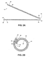
- FIG. 2A and 2B another material 10 and sleeve 12 is shown constructed according to another embodiment of the invention.
- the material 10 has an inner layer 22 and an outer layer 24, wherein each of the respective layers 22, 24 has warp-wise extending yarns 26 and weft-wise or fill yarns 28.
- the warp yarns 26 (designated by "X”, representing one type of yarn) of the inner layer 22 are provided as conductive yarns to provide EMI protection to the elongate members within the cavity of the sleeve 12, while at least some of the warp yarns 26 (designated by "O", representing a different type of yarn than that designated by "X") of the outer layer 24 are provided as different types of yarns.
- the warp yarns 26 (designated by "X") adjacent the free end 29 of the outer layer 24 can be provided as conductive yarns, and can be the same type as used in the inner layer 22, while the remaining warp yarns 26 (designated by "O") of the outer layer 24 are provided having any suitable color, for appearance purposes, and having high abrasion resistance and insulative properties to protect the elongate members within the cavity of the sleeve 12.
- the conductive warp yarns 26 ("X") of the outer layer 24 adjacent the free edge 29 are brought into engagement with the conductive warp yarns 26 ("X") of the inner layer 22 to provide a complete, circumferential conductive layer or inner wall about the elongate members within the cavity of the sleeve 12.
- the remaining non-conductive warp yarns 26 ("O") of the outer layer 24 extend completely circumferentially about the outer surface of the sleeve 12 to provide an outer wall having abrasion resistance and insulative properties to the sleeve 12.
- FIG. 3A and 3B another material 10 and sleeve 12 is shown constructed according to another embodiment of the invention.
- the material 10 has an inner layer 30 and an outer layer 32, wherein each of the respective layers 30, 32 has warp-wise extending yarns 34 and weft-wise or fill yarns 36.
- the inner and outer layers 30, 32 are constructed similarly as described above in connection with the inner and outer layers 14, 16, however, the inner layer 30 is constructed having an increased width extending along a direction transverse to the length of the sleeve 12 relative to the outer layer 32.
- the warp yarns 34 of the inner layer 30 are provided as conductive yarns ("X"), whether coated with metal or in wire filament form, while the warp yarns 34 of the outer layer 32 are provided as non-conductive warp yarns ("O"). Accordingly, upon being cigarette wrapped, the inner layer 30 extends completely circumferentially into electrical communication with itself to provide complete EMI protection circumferentially about the elongate members within the sleeve 12. Meanwhile, the outer layer 32 preferably extends completely circumferentially about the inner conductive yarns ("X”) to provide complete abrasion resistance and insulative properties to the inner conductive yarns and elongate members being protected within the sleeve 12.
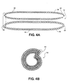
- FIG. 4A and 4B another material 10 and sleeve 12 is shown constructed according to another embodiment of the invention.
- the material 10 has an inner layer 38 and an outer layer 40, wherein each of the respective layers 38, 40 has warp-wise extending yarns 42 and weft-wise or fill yarns 44.
- Both the inner and outer layers 38, 40 are woven as a tubular configurations.
- the tubular inner layer 38 is attached to the tubular outer layer 40 via the weft yarns 44 in each the inner and outer layers 38, 40 being hooked or linked about respective warp yarns 42 extending along the length of the inner and outer layers.
- the tubular inner layer 38 is represented as being woven with electrically conductive warp yarns 42 ("X"), while the tubular outer layer is woven with abrasion resistant, insulative warp yarns 42 ("O”), as discussed above.
- the inner and outer layers 38, 40 provide a wall having four discrete layers. Two of the layers of the sleeve wall are formed from the inner layer 38 and two of the layers are formed from the outer layer 40.
- FIG. 5A and 5B another material 10 and sleeve 12 is shown constructed according to another embodiment of the invention.
- the material 10 has an inner layer 46 and an outer layer 48, wherein each of the respective layers 46, 48 has warp-wise extending yarns 50 and weft-wise or fill yarns 52.
- the inner and outer layers 46, 48 are formed similarly as described above in connection with Figures 4A, 4B , however, at least one or both layers 46, 48 are formed with their respective warp yarns 50 being of different types.
- the tubular inner layer 46 can have its innermost layer 47 formed with non-abrasive, electrically conductive yarns ("X"), while the outermost layer 49 of the inner layer 46 can be formed with different electrically conductive yarns ("--”) or otherwise, as desired.
- the tubular outer layer 48 can be formed with an innermost layer 51 of non-abrasive, electrically conductive yarns ("X") or otherwise, as desired, while the outermost layer 53 of the outer layer 48 can be formed with abrasion resistant, colored, insulative yarns ("O"), as described above.
- FIG. 6A and 6B another material 10 and sleeve 12 is shown constructed according to another embodiment of the invention.
- the material 10 has an inner layer 54 and an outer layer 56, wherein each of the respective layers 54, 56 has warp-wise extending yarns 58 and weft-wise or fill yarns 60.
- the inner layer 54 is formed by inner-most portions of two separate tubular sections 61, 63
- the outer layer 56 is formed by outer-most portions of the tubular sections 61, 63.
- the tubular sections 61, 63 are joined at diametrically opposite sides by weft yarns 60 looping about warp yarns 58, as discussed above.
- the tubular sections 61, 63 are moved outwardly from one another to form the inner cavity of the sleeve 12.
- the tubular section 61 is illustrated as being formed with one type of warp yarns, such as abrasion resistant, insulative yarns ("X"), while the other tubular section 63 is illustrated as being formed with another type of warp yarns, such as non-abrasive, slick and insulative yarns ("O"), for example.
- the inner layer 56 is provided both abrasion resistant, insulative warp yarns ("X") and non-abrasive, slick and insulative warp yarns ("O").
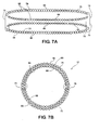
- FIG. 7A and 7B another material 10 and sleeve 12 is shown constructed according to another embodiment of the invention.
- the material 10 has an inner layer 64 and an outer layer 66, wherein each of the respective layers 64, 66 has warp-wise extending yarns 68 and weft-wise or fill yarns 70.
- the inner layer 64 is formed by inner-most portions of two separate tubular sections 71, 73 and the outer layer 66 is formed by outer-most portions of the tubular sections 71, 73.
- the tubular sections 71, 73 are joined at diametrically opposite sides by selected weft yarns 70 looping about selected warp yarns 68, as discussed above.
- the tubular sections 71, 73 are moved outwardly from one another to form the inner cavity of the sleeve 12.
- the tubular sections 71, 73 are each illustrated as being formed with two types of warp yarns, such as abrasion resistant, insulative yarns ("O"), and non-abrasive, slick and insulative yarns ("X”), for example.
- abrasion resistant, insulative yarns such as abrasion resistant, insulative yarns (“O")
- X non-abrasive, slick and insulative yarns
- FIG. 8A and 8B another material 10 and sleeve 12 is shown constructed according to another embodiment of the invention.
- the material 10 has an inner layer 74 and an outer layer 76, wherein each of the respective layers 74, 76 has warp-wise extending yarns 78 and weft-wise or fill yarns 80.
- the inner layer 74 is formed as a single layer, while the outer layer 76 is formed as a tubular section having two opposing layers.
- the inner layer 74 and outer layer 76 are constructed integrally with one another in a single weaving operation via weft yarns 80 from each layer 74, 76 looping about warp yarns 78 from the other respective layer 74, 76.
- the interconnection of the inner and outer layers 74, 76 forms an elongate edge 81 of the material 10.
- the material 10 is cigarette wrapped with the inner layer 74 facing inwardly to form an inner cavity, while the outer layer 76 faces outwardly.
- the inner layer 74 is preferably formed with non-abrasion, slick and insulative warp yarns 78 ("X") and the outer layer 76 is provided with abrasion resistant, insulative warp yarns 78 ("O"). Accordingly, as discussed above in connection with the other embodiments, the inner layer allow easy installation of the elongate members into the cavity without causing damage, while the outer layer 76 provides the necessary protection against abrasion and thermal conditions.
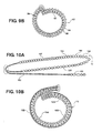
- FIG. 9A and 9B another material 10 and sleeve 12 is shown constructed according to another embodiment of the invention.
- the material 10 is similar to the material shown in Figures 8A and 8B , having a single ply inner layer 92 and a tubular, two layered outer layer 94.
- the outer layer 94 rather than being formed with the same warp yarns throughout, has an innermost layer 95 formed of one type of warp yarn 96, such as electrically conductive yarns ("X"), and an outermost layer 97 formed of a different type of warp yarns 98, such as colored, abrasion resistant and insulative yarns ("O").
- the material and sleeve formed therefrom is similar to that discussed and shown in connection with Figures 8A and 8B .
- FIG. 10A and 10B another material 10 and sleeve 12 is shown constructed according to another embodiment of the invention.
- the material 10 is similar to the material shown in Figures 9A and 9B , having a single ply layer and a tubular, two ply layer, however, the tubular layer provides an inner layer 100 and the single ply layer forms an outer layer 102.
- the tubular inner layer 100 is formed with an innermost layer 103 formed substantially of one type of warp yarn 106, such as non-abrasive, slick or lubricious yarns ("O"). However, the innermost layer 103 has at least a portion constructed with electrically conductive warp yarns 107 ("X”) adjacent one of its ends.
- X electrically conductive warp yarns 107
- the inner layer 100 further includes an outermost layer 105 formed substantially of electrically conductive warp yarns ("X").
- the single ply outer layer 102 is attached at one end to the tubular layer 100, via interlocking weft and warp yarns, as described above in the various embodiments, and is formed with warp yarns differing from the inner layer warp yarns at least in part, wherein the outer layer warp yarns can be colored, abrasion resistant and insulative yarns.
- the outer layer 100 has electrically conductive warp yarns 109 adjacent a free end configured for mating electrical engagement with the electrically conductive yarns 107 in the innermost layer 103 of the inner layer 100.
- a complete circumferential electrically conductive blanket is formed about elongate members with a cavity of the sleeve 12 by the electrical communication established between the conductive warp yarns 107 in the innermost layer 103, the conductive warp yarns 109 in the outer layer 102, and the conductive warp yarns in the outermost layer 105 upon wrapping the material 10 in a cigarette wrapped overlapping fashion.
Landscapes
- Engineering & Computer Science (AREA)
- Textile Engineering (AREA)
- Architecture (AREA)
- Civil Engineering (AREA)
- Structural Engineering (AREA)
- Mechanical Engineering (AREA)
- Woven Fabrics (AREA)
- Laminated Bodies (AREA)
- Gloves (AREA)
- Professional, Industrial, Or Sporting Protective Garments (AREA)
Description
- This application claims the benefit of
U.S. Provisional Application Serial No. 61/019,458, filed January 7, 2008 - This invention relates generally to protective textile sleeves, and more particularly to multilayer textile sleeves and their method of construction.
- It is known to first fabricate individual layers of textile material and then attach the individual layers to one another in a secondary operation to construct a single piece multilayer material. For example, if the desired multilayer material being constructed requires an inner layer to provide one type of property, such as low friction, and an outer layer to provide another type of property, such as insulation and!or abrasion resistance, one piece of textile material can be constructed in a first operation; a second piece of material can be constructed in a second operation, and then, the first and second pieces of material can be joined in a third operation to provide the single piece multilayer material. Although the end product is made having the desired properties, it comes at an expense, particularly given the manufacturing inefficiencies compiled over numerous operations.
- A multilayer textile material is provided having a first layer constructed at least in part from one type of yarn and a second layer overlapped at least in part by the first layer, wherein the second layer is constructed at least in part from a second type of yarn that is different from the yarn used to construct the first layer. The first and second layers are integrally connected to one another in the process used to construct the first and second layers.
- According to one aspect of the invention, weft yarns in the first layer hook warp yarns in the second layer, and weft yarns in the second layer hook warp yarns in the first layer to interlock the first and second layers to one another.
- According to another aspect of the invention, the first and/or second layers have at least some warp yarns with different physical properties.
- According to another aspect of the invention, the multilayer material has a third layer overlapped at least in part by the first and second layers, wherein the third layer is constructed in a single process with the first and second layers.
- According to another aspect of the invention, the third layer has at least some warp yarns with different physical properties from the first and/or second layers.
- According to another aspect of the invention, the multilayer material is formed into a protective tubular sleeve.
- According to another aspect of the invention, at least one of the first, second or third layers provides the tubular sleeve with a circumferentially continuous conductive layer.
- According to another aspect of the invention, the first and second or second and third layers are formed as a continuous tubular wall with the remaining layer extending outwardly from the tubular wall to a free end.
- According to another aspect of the invention, the multilayer material has a fourth layer overlapped at least in part by the first, second and third layers, wherein the fourth layer is constructed in a single process with the first, second and third layers.
- According to another aspect of the invention, the first and second layers are formed as a first continuous tubular wall and the third and fourth layers are formed as a second continuous tubular wall, wherein the first and second tubular walls are constructed in a single process.
- According to another aspect of the invention, the first and second tubular walls provide a tubular sleeve having a dual layered wall.
- According to another aspect of the invention, the first and second tubular walls provide a tubular sleeve having a four layered wall.
- According to another aspect of the invention, a method of constructing a multilayer textile sleeve is provided. The method comprises weaving an outer layer having a first warp yarn extending along a length direction of the sleeve and a weft yarn extending substantially transversely to the length direction; weaving an inner layer having a second warp yarn extending along the length direction of the sleeve and a weft yarn extending substantially transversely to the length direction, and providing the second warp yarn as a different type of yarn than the first warp yarn, and connecting the outer layer and the inner layer to one another by interlinking the weft yarn of the outer layer with at least some of the second warp yarns of the inner layer and by interlinking the weft yarn of the inner layer with at least some of the first warp yarns of the outer layer.
- These and other aspects, features and advantages of a multilayer sleeve constructed in accordance with the invention will become more readily appreciated when considered in connection with the following detailed description of presently preferred embodiments and best mode, appended claims and accompanying drawings, in which:
-
Figure 1A is a diagrammatic end view of a multilayer material constructed in accordance with one embodiment of the invention; -
Figure 1B is a diagrammatic end view of the material ofFigure 1A formed into a protective sleeve; -
Figure 2A is a diagrammatic end view of a multilayer material constructed in accordance with another embodiment of the invention; -
Figure 2B is a diagrammatic end view of the material ofFigure 2A formed into a protective sleeve; -
Figure 3A is a diagrammatic end view of a multilayer material constructed in accordance with yet another embodiment of the invention; -
Figure 3B is a diagrammatic end view of the material ofFigure 3A formed into a protective sleeve; -
Figure 4A is a diagrammatic end view of a multilayer material constructed in accordance with yet another embodiment of the invention; -
Figure 4B is a diagrammatic end view of the material ofFigure 4A formed into a protective sleeve; -
Figure 5A is a diagrammatic end view of a multilayer material constructed in accordance with yet another embodiment of the invention; -
Figure 5B is a diagrammatic end view of the material ofFigure 5A formed into a protective sleeve; -
Figure 6A is a diagrammatic end view of a multilayer material constructed in accordance with yet another embodiment of the invention; -
Figure 6B is a diagrammatic end view of the material ofFigure 6A formed into a protective sleeve; -
Figure 7A is a diagrammatic end view of a multilayer material constructed in accordance with yet another embodiment of the invention; -
Figure 7B is a diagrammatic end view of the material ofFigure 7A formed into a protective sleeve; -
Figure 8A is a diagrammatic end view of a multilayer material constructed in accordance with yet another embodiment of the invention; -
Figure 8B is a diagrammatic end view of the material ofFigure 8A formed into a protective sleeve; -
Figure 9A is a diagrammatic end view of a multilayer material constructed in accordance with yet another embodiment of the invention; -
Figure 9B is a diagrammatic end view of the material ofFigure 9A formed into a protective sleeve; -
Figure 10A is a diagrammatic end view of a multilayer material constructed in accordance with yet another embodiment of the invention; and -
Figure 10B is a diagrammatic end view of the material ofFigure 10A formed into a protective sleeve. - Referring in more detail to the drawings,
Figures 1A-10A illustrate diagrammaticallyvarious textile materials 10 constructed in accordance with different embodiments of the invention, whereinFigures 1B-10B illustrate therespective materials 10 formed intoprotective sleeves 12. Each of thetextile materials 10 is constructed having overlapping layers of yarn, wherein at least a portion of one of the layers is constructed with a different yarn type than the overlapped layer. Throughout the description, and as illustrated in the drawings, the different yarns types are designated by "X" and "O". The yarns are selected for each of the material layers to provide thematerial 10 andsleeves 12 formed therewith with the desired properties, depending on their intended application of use. The different yarns are interlinked, such as by being woven with one another in a continuous, single weaving process, such that secondary operations are not needed to join the overlapping layers to one another. One weaving process contemplated herein for constructing thematerials 10 is a dual pick insertion process, although other weaving processes are contemplated herein that provide a similar material in a single process. - In
Figure 1A , thematerial 10 is constructed having two generally equal length layers overlapping one another, with one layer being aninner layer 14 and the other being anouter layer 16. Thelayers material 10. The mechanism attaching thelayers layers layers warp-wise extending yarns 18, which extend along the length of the sleeve 12 (in and out of the page as shown inFigures 1-10 ), and weft-wise or fillyarns 20, which extend along the width of thesleeve 12 and thus, substantially transverse to the length of thesleeve 12. - Each of the
layers warp yarns 18, either monofilament or multifilament, with one layer forming theinner layer 14 and the other layer forming theouter layer 16. The warp yarns 18 (designated by "X", representing one type of yarn) in theinner layer 14 are provided as a non-abrasive, slick and insulative yarns so as to provide insulation to wires or other elongate members with a cavity of thesleeve 12, while also allowing the elongate members to be easily installed within the cavity without causing damage to the elongate members. In contrast, the warp yarns 18 (designated by "O", representing another type of yarn different from the "X" type of yarn) in theouter layer 16 are provided having any suitable color, for appearance purposes, and having high abrasion resistance and insulative properties to protect the elongate members within the cavity of thesleeve 12. - The
weft yarns 20 can be provided having any desired properties in each of thelayers material 10 into a self-curling, tubular sleeve, theweft yarns 20 can be provided of any heat settable monofilament, such as PET, for example. At least some of theweft filaments 20 of theinner layer 14 are interlocked or interlinked with at least some of thewarp yarns 18 of theouter layer 16, and at least some of theweft yarns 20 of theouter layer 16 are interlocked or interlinked with at least some of thewarp yarns 18 of theinner layer 14 to interlock the connection edges 17, 19 with one another and to provide thematerial 10 as a unitary, single piece member in a single manufacturing process. - The
material 10, preferably having heatformable weft yarns 20, can be heat formed or set in a heat-setting process into the desired, substantially closed tubular sleeve shape, wherein theinner layer 14 preferably overlaps theouter layer 16 in a so called "cigarette wrap" form to circumferentially enclose the elongate members within the cavity of thesleeve 12. Although thesleeve 12 is ultimately substantially closed, it should be recognized that thesleeve 12 is an open-type sleeve, which means thesleeve 12 is not constructed having a circumferentially closed wall, but rather, has overlappingfree edges 29 extending along the length of thesleeve 12 that can be biased away from one another into an open configuration allowing access to the cavity of the sleeve. Of course, rather than heat-setting the material into the tubular sleeve configuration, fasteners could be provided along a longitudinal seam of the sleeve, such as a hook and loop fastener, for example, thereby allowing the material to be manually wrapped in use and fastened about the elongate members. - As shown in
Figures 2A and 2B , anothermaterial 10 andsleeve 12 is shown constructed according to another embodiment of the invention. Thematerial 10 has aninner layer 22 and anouter layer 24, wherein each of therespective layers yarns 26 and weft-wise or fillyarns 28. The warp yarns 26 (designated by "X", representing one type of yarn) of theinner layer 22 are provided as conductive yarns to provide EMI protection to the elongate members within the cavity of thesleeve 12, while at least some of the warp yarns 26 (designated by "O", representing a different type of yarn than that designated by "X") of theouter layer 24 are provided as different types of yarns. The warp yarns 26 (designated by "X") adjacent thefree end 29 of theouter layer 24 can be provided as conductive yarns, and can be the same type as used in theinner layer 22, while the remaining warp yarns 26 (designated by "O") of theouter layer 24 are provided having any suitable color, for appearance purposes, and having high abrasion resistance and insulative properties to protect the elongate members within the cavity of thesleeve 12. - As shown in
Figure 2B , when thematerial 10 is cigarette wrapped, the conductive warp yarns 26 ("X") of theouter layer 24 adjacent thefree edge 29 are brought into engagement with the conductive warp yarns 26 ("X") of theinner layer 22 to provide a complete, circumferential conductive layer or inner wall about the elongate members within the cavity of thesleeve 12. The remaining non-conductive warp yarns 26 ("O") of theouter layer 24 extend completely circumferentially about the outer surface of thesleeve 12 to provide an outer wall having abrasion resistance and insulative properties to thesleeve 12. - As shown in
Figures 3A and 3B , anothermaterial 10 andsleeve 12 is shown constructed according to another embodiment of the invention. Thematerial 10 has aninner layer 30 and anouter layer 32, wherein each of therespective layers yarns 34 and weft-wise or fillyarns 36. The inner andouter layers outer layers inner layer 30 is constructed having an increased width extending along a direction transverse to the length of thesleeve 12 relative to theouter layer 32. As in the previous embodiment, thewarp yarns 34 of theinner layer 30 are provided as conductive yarns ("X"), whether coated with metal or in wire filament form, while thewarp yarns 34 of theouter layer 32 are provided as non-conductive warp yarns ("O"). Accordingly, upon being cigarette wrapped, theinner layer 30 extends completely circumferentially into electrical communication with itself to provide complete EMI protection circumferentially about the elongate members within thesleeve 12. Meanwhile, theouter layer 32 preferably extends completely circumferentially about the inner conductive yarns ("X") to provide complete abrasion resistance and insulative properties to the inner conductive yarns and elongate members being protected within thesleeve 12. - As shown in
Figures 4A and 4B , anothermaterial 10 andsleeve 12 is shown constructed according to another embodiment of the invention. Thematerial 10 has aninner layer 38 and anouter layer 40, wherein each of therespective layers yarns 42 and weft-wise or fillyarns 44. Both the inner andouter layers inner layer 38 is attached to the tubularouter layer 40 via theweft yarns 44 in each the inner andouter layers respective warp yarns 42 extending along the length of the inner and outer layers. The tubularinner layer 38 is represented as being woven with electrically conductive warp yarns 42 ("X"), while the tubular outer layer is woven with abrasion resistant, insulative warp yarns 42 ("O"), as discussed above. - As shown in
Figure 4B , upon being cigarette-wrapped, the inner andouter layers inner layer 38 and two of the layers are formed from theouter layer 40. - As shown in
Figures 5A and 5B , anothermaterial 10 andsleeve 12 is shown constructed according to another embodiment of the invention. Thematerial 10 has aninner layer 46 and anouter layer 48, wherein each of therespective layers yarns 50 and weft-wise or fillyarns 52. The inner andouter layers Figures 4A, 4B , however, at least one or bothlayers respective warp yarns 50 being of different types. For example, the tubularinner layer 46 can have itsinnermost layer 47 formed with non-abrasive, electrically conductive yarns ("X"), while theoutermost layer 49 of theinner layer 46 can be formed with different electrically conductive yarns ("--") or otherwise, as desired. The tubularouter layer 48 can be formed with aninnermost layer 51 of non-abrasive, electrically conductive yarns ("X") or otherwise, as desired, while theoutermost layer 53 of theouter layer 48 can be formed with abrasion resistant, colored, insulative yarns ("O"), as described above. - As shown in
Figures 6A and 6B , anothermaterial 10 andsleeve 12 is shown constructed according to another embodiment of the invention. Thematerial 10 has aninner layer 54 and anouter layer 56, wherein each of therespective layers yarns 58 and weft-wise or fillyarns 60. Theinner layer 54 is formed by inner-most portions of two separatetubular sections outer layer 56 is formed by outer-most portions of thetubular sections tubular sections weft yarns 60 looping aboutwarp yarns 58, as discussed above. - As shown in
Figure 6B , thetubular sections sleeve 12. Thetubular section 61 is illustrated as being formed with one type of warp yarns, such as abrasion resistant, insulative yarns ("X"), while the othertubular section 63 is ilustrated as being formed with another type of warp yarns, such as non-abrasive, slick and insulative yarns ("O"), for example. As such, theinner layer 56 is provided both abrasion resistant, insulative warp yarns ("X") and non-abrasive, slick and insulative warp yarns ("O"). - As shown in
Figures 7A and 7B , anothermaterial 10 andsleeve 12 is shown constructed according to another embodiment of the invention. Thematerial 10 has aninner layer 64 and anouter layer 66, wherein each of therespective layers yarns 68 and weft-wise or fillyarns 70. As with the embodiment discussed in connection withFigures 6A, 6B , theinner layer 64 is formed by inner-most portions of two separatetubular sections outer layer 66 is formed by outer-most portions of thetubular sections tubular sections weft yarns 70 looping about selectedwarp yarns 68, as discussed above. - As shown in
Figure 7B , thetubular sections sleeve 12. Thetubular sections warp yarns 68 within the separatetubular sections inner layer 64 is provided entirely with the non-abrasion, slick and insulative yarns ("X") and theouter layer 66 is provided with the abrasion resistant, insulative warp yarns ("O"). - As shown in
Figures 8A and 8B , anothermaterial 10 andsleeve 12 is shown constructed according to another embodiment of the invention. Thematerial 10 has aninner layer 74 and anouter layer 76, wherein each of therespective layers yarns 78 and weft-wise or fillyarns 80. Theinner layer 74 is formed as a single layer, while theouter layer 76 is formed as a tubular section having two opposing layers. Similarly as described above, theinner layer 74 andouter layer 76 are constructed integrally with one another in a single weaving operation viaweft yarns 80 from eachlayer warp yarns 78 from the otherrespective layer outer layers material 10. - As shown in
Figure 8B , thematerial 10 is cigarette wrapped with theinner layer 74 facing inwardly to form an inner cavity, while theouter layer 76 faces outwardly. Theinner layer 74 is preferably formed with non-abrasion, slick and insulative warp yarns 78 ("X") and theouter layer 76 is provided with abrasion resistant, insulative warp yarns 78 ("O"). Accordingly, as discussed above in connection with the other embodiments, the inner layer allow easy installation of the elongate members into the cavity without causing damage, while theouter layer 76 provides the necessary protection against abrasion and thermal conditions. - As shown in
Figures 9A and9B , anothermaterial 10 andsleeve 12 is shown constructed according to another embodiment of the invention. Thematerial 10 is similar to the material shown inFigures 8A and 8B , having a single plyinner layer 92 and a tubular, two layeredouter layer 94. However, theouter layer 94, rather than being formed with the same warp yarns throughout, has aninnermost layer 95 formed of one type ofwarp yarn 96, such as electrically conductive yarns ("X"), and anoutermost layer 97 formed of a different type ofwarp yarns 98, such as colored, abrasion resistant and insulative yarns ("O"). Otherwise the material and sleeve formed therefrom is similar to that discussed and shown in connection withFigures 8A and 8B . - As shown in
Figures 10A and 10B , anothermaterial 10 andsleeve 12 is shown constructed according to another embodiment of the invention. Thematerial 10 is similar to the material shown inFigures 9A and9B , having a single ply layer and a tubular, two ply layer, however, the tubular layer provides aninner layer 100 and the single ply layer forms anouter layer 102. The tubularinner layer 100 is formed with aninnermost layer 103 formed substantially of one type ofwarp yarn 106, such as non-abrasive, slick or lubricious yarns ("O"). However, theinnermost layer 103 has at least a portion constructed with electrically conductive warp yarns 107 ("X") adjacent one of its ends. Theinner layer 100 further includes anoutermost layer 105 formed substantially of electrically conductive warp yarns ("X"). The single plyouter layer 102 is attached at one end to thetubular layer 100, via interlocking weft and warp yarns, as described above in the various embodiments, and is formed with warp yarns differing from the inner layer warp yarns at least in part, wherein the outer layer warp yarns can be colored, abrasion resistant and insulative yarns. However, theouter layer 100 has electricallyconductive warp yarns 109 adjacent a free end configured for mating electrical engagement with the electricallyconductive yarns 107 in theinnermost layer 103 of theinner layer 100. Accordingly, a complete circumferential electrically conductive blanket is formed about elongate members with a cavity of thesleeve 12 by the electrical communication established between theconductive warp yarns 107 in theinnermost layer 103, theconductive warp yarns 109 in theouter layer 102, and the conductive warp yarns in theoutermost layer 105 upon wrapping the material 10 in a cigarette wrapped overlapping fashion. - Obviously, many modifications and variations of the present invention are possible in light of the above teachings. It is, therefore, to be understood that within the scope of any claims stemming from this disclosure, the invention may be practiced otherwise than as specifically described.
Claims (13)
- A circumferentially open multilayer textile sleeve (12), comprising:an outer layer (16; 24; 32; 40; 48; 76; 94; 102) constructed at least in part from a first warp yarn (18; 26; 34; 42; 50; 78) extending along a length direction of said sleeve and a weft yarn (20; 28; 36; 44; 52; 80) extending substantially transversely to said length direction;an inner layer (14; 22; 30; 38; 46; 74; 92; 100) constructed at least in part from a second warp yarn extending along said length direction of said sleeve and a weft yarn extending substantially transversely to said length direction, said second warp yarn being a different type of yarn than said first warp yarn, andsaid outer layer and said inner layer being connected to one another by interlinking said weft yarn of said outer layer with at least some of said second warp yarns of said inner layer and by interlinking said weft yarn of said inner layer with at least some of said first warp yarns of said outer layer, said outer layer and said inner layer each having free edges (29) extending along said length direction of said sleeve and having opposite connection edges (19, 17) extending along said length direction of said sleeve, said connection edges (19, 17) being attached to one another by said weft yarns (20; 28; 36; 44; 52; 80) of said outer and inner layers, while the remaining portion of said outer layer and the remaining portion of said inner layer remain detached from each other.
- The multilayer textile sleeve of claim 1 wherein at least some of said weft yarns (20; 28; 36; 44; 52; 80) are heat set such that said outer and inner layers are biased into a self-curled cigarette configuration.
- The multilayer textile sleeve of claim 1 wherein said second warp yarn is an electrically conductive yarn and at least some of said first warp yarn is a non-conductive, insulative yarn.
- The multilayer textile sleeve of claim 3 wherein at least some of said first warp yarn is a conductive yarn arranged in electrical communication with said conductive yarn of said inner layer to provide said sleeve with a circumferentially continuous, electrically conductive wall.
- The multilayer textile sleeve of claim 1 wherein said inner layer (38) has two layers and said outer layer (40) has two layers, said inner and outer layers providing said sleeve with a wall of four layers.
- The multilayer textile sleeve of claim 5 wherein said two layers of said inner layer (38) are constructed at least in part of different types of warp yarn.
- The multilayer textile sleeve of claim 6 wherein said two layers of said outer layer are constructed of different types of warp yarn.
- The multilayer textile sleeve of claim 1 wherein said inner layer (30) has a greater width than said outer layer (32).
- The multilayer textile sleeve of claim 1 wherein said sleeve has a pair of tubular sections extending along said length direction and said outer and inner layers are formed from separate portions of each tubular section.
- A method of constructing a circumferentially open multilayer textile sleeve, comprising:weaving an outer layer having a free edge (29) extending along the length direction of the sleeve and having an opposite connection edge (19) extending along the length direction of the sleeve and having a first warp yarn extending along a length direction of the sleeve and a weft yarn extending substantially transversely to the length direction;weaving an inner layer having a free edge (29) extending along the length direction of the sleeve and having an opposite connection edge (17) extending along the length direction of the sleeve and having a second warp yarn extending along the length direction of the sleeve and a weft yarn extending substantially transversely to the length direction, and providing the second warp yarn as a different type of yarn than the first warp yarn, andconnecting the outer layer and the inner layer to one another at said connecting edges (19, 17) by interlinking the weft yarn of the outer layer with at least some of the second warp yarns of the inner layer and by interlinking the weft yarn of the inner layer with at least some of the first warp yarns of the outer layer, but leaving the remaining portions of the outer and inner layers in detached relation with one another.
- The method of claim 10 further including heat setting at least some of the weft yarns and causing the inner and outer layers to be biased into a self-curled cigarette configuration.
- The method of claim 10 further including providing the second warp yarn as an electrically conductive yarn and providing at least some of the first warp yarn as a non-conductive, insulative yarn.
- The method of claim 12 further including providing at least some of the first warp yarn as a conductive yarn and configuring the conductive yarn of the outer layer in electrical communication with the conductive yarn of the inner layer to provide the sleeve with a circumferentially continuous, electrically conductive wall.
Applications Claiming Priority (3)
| Application Number | Priority Date | Filing Date | Title |
|---|---|---|---|
| US1945808P | 2008-01-07 | 2008-01-07 | |
| US12/349,264 US9028937B2 (en) | 2008-01-07 | 2009-01-06 | Multilayer protective textile sleeve and method of construction |
| PCT/US2009/030257 WO2009089238A2 (en) | 2008-01-07 | 2009-01-07 | Multilayer protective textile sleeve and method of construction |
Publications (3)
| Publication Number | Publication Date |
|---|---|
| EP2231389A2 EP2231389A2 (en) | 2010-09-29 |
| EP2231389A4 EP2231389A4 (en) | 2012-10-03 |
| EP2231389B1 true EP2231389B1 (en) | 2014-06-18 |
Family
ID=40853739
Family Applications (1)
| Application Number | Title | Priority Date | Filing Date |
|---|---|---|---|
| EP20090701023 Active EP2231389B1 (en) | 2008-01-07 | 2009-01-07 | Multilayer protective textile sleeve and method of construction |
Country Status (8)
| Country | Link |
|---|---|
| US (1) | US9028937B2 (en) |
| EP (1) | EP2231389B1 (en) |
| JP (1) | JP5306372B2 (en) |
| KR (1) | KR101504982B1 (en) |
| CN (1) | CN101945755B (en) |
| BR (1) | BRPI0906254B1 (en) |
| CA (1) | CA2709706C (en) |
| WO (1) | WO2009089238A2 (en) |
Cited By (1)
| Publication number | Priority date | Publication date | Assignee | Title |
|---|---|---|---|---|
| WO2024073670A1 (en) * | 2022-09-30 | 2024-04-04 | Federal-Mogul Powertrain Llc | Knit tubular thermal sleeve with wrappable cover and method of construction thereof |
Families Citing this family (33)
| Publication number | Priority date | Publication date | Assignee | Title |
|---|---|---|---|---|
| US8898821B2 (en) | 2009-05-19 | 2014-12-02 | Southern Mills, Inc. | Flame resistant fabric with anisotropic properties |
| WO2011009112A2 (en) * | 2009-07-17 | 2011-01-20 | Federal-Mogul Powertrain,Inc | Tri-layer knit fabric, thermal protective members formed therefrom and methods of construction thereof. |
| AR080651A1 (en) * | 2010-02-19 | 2012-04-25 | Nicolon Corp Doing Business As Tencate Geosynthetics North America | WASTE PROTECTION FOR GEOCONTENDERS, MANUFACTURING PROCEDURE AND USE PROCEDURE |
| CN103155319B (en) * | 2010-05-10 | 2016-08-03 | 费德罗-莫格尔动力系公司 | Non-woven self-wrapping thermal sleeve and manufacturing method thereof |
| WO2012024272A1 (en) * | 2010-08-16 | 2012-02-23 | Federal-Mogul Powertrain, Inc. | Non-kinking self-wrapping woven sleeve and method of construction thereof |
| EP2647749A4 (en) * | 2010-11-29 | 2014-04-30 | Toray Industries | Fabric and covering material for electrical wiring using same |
| WO2012078833A1 (en) * | 2010-12-08 | 2012-06-14 | Federal-Mogul Powertrain, Inc. | Textile sleeve with protective coating and method of construction thereof |
| CN103596808B (en) * | 2011-04-18 | 2016-05-11 | 费德罗-莫格尔动力系公司 | A kind of multi-layered textile sleeve and building method thereof |
| EP2719039B1 (en) * | 2011-06-09 | 2015-05-06 | Federal-Mogul Powertrain, Inc. | Reflective textile sleeve and method of construction thereof |
| USD693773S1 (en) * | 2012-01-18 | 2013-11-19 | Kevin F. Chen | Cable sleeve |
| US9386816B2 (en) | 2012-02-14 | 2016-07-12 | International Textile Group, Inc. | Fire resistant garments containing a high lubricity thermal liner |
| RU2618419C2 (en) * | 2012-03-01 | 2017-05-03 | Федерал-Могал Пауэртрейн, Инк. | Protective textile shell for elongated objects protection and method for its manufacture |
| US8875746B2 (en) * | 2012-10-02 | 2014-11-04 | Federal-Mogul Powertrain, Inc. | Textile sleeve with twisted hybrid fill yarn and method of construction thereof |
| KR102145648B1 (en) * | 2013-02-04 | 2020-08-18 | 페더럴-모걸 파워트레인 엘엘씨 | Non-kinking self-wrapping woven sleeve and method of construction thereof |
| US9277684B2 (en) * | 2013-03-13 | 2016-03-01 | Federal-Mogul Powertrain, Inc. | Self-wrapping EMI shielding textile sleeve and method of construction thereof |
| US9062396B2 (en) | 2013-03-15 | 2015-06-23 | Federal-Mogul Powertrain, Inc. | Corrugated knit sleeve and method of construction thereof |
| CN103879036A (en) * | 2014-04-08 | 2014-06-25 | 蔡宝祥 | High-strength fiber double-layer interweaved composite hose and production method thereof |
| KR20170031731A (en) * | 2014-07-16 | 2017-03-21 | 페더럴-모걸 파워트레인 엘엘씨 | Wrappable abrasion resistant, reflective thermal protective textile sleeve and method of construction thereof |
| US10542645B2 (en) * | 2015-04-17 | 2020-01-21 | Federal-Mogul Powertrain Llc | EMI protective sleeve and method of construction thereof |
| US10405594B2 (en) | 2015-05-21 | 2019-09-10 | International Textile Group, Inc. | Inner lining fabric |
| US10337130B2 (en) | 2016-02-01 | 2019-07-02 | The Boeing Company | Metal alloy knit fabric for high temperature insulating materials |
| US10982355B2 (en) * | 2016-07-25 | 2021-04-20 | Federal-Mogul Powertrain Llc | Knit tubular protective sleeve and method of construction thereof |
| US11180872B2 (en) | 2016-08-24 | 2021-11-23 | Federal-Mogul Powertrain Llc | Impact resistant, shrinkable woven tubular sleeve and method of construction thereof |
| CN106532592A (en) * | 2016-11-07 | 2017-03-22 | 深圳市骏鼎达新材料股份有限公司 | Line protection sleeve |
| CN109996912B (en) * | 2016-11-28 | 2021-10-29 | 格兰博格国际有限公司 | Three-dimensional 3D knitted fabric and its manufacturing method |
| CA3171137A1 (en) | 2019-03-28 | 2020-10-01 | Southern Mills, Inc. | Flame resistant fabrics |
| CN114375353B (en) * | 2019-09-10 | 2023-08-11 | 费德罗-莫格尔动力系公司 | Corrugated woven sleeve and method of making same |
| US11401631B2 (en) * | 2019-10-28 | 2022-08-02 | Federal-Mogul Powertrain Llc | Impact resistant, wrappable multilayered woven sleeve and method of construction thereof |
| US11686022B2 (en) | 2020-02-11 | 2023-06-27 | Federal-Mogul Powertrain Llc | Impact resistant, wrappable, corrugated, multilayered woven sleeve and method of construction thereof |
| PE20240506A1 (en) * | 2020-08-27 | 2024-03-15 | Sanexen Env Services Inc | TUBULAR FABRIC COVERING |
| KR20240037351A (en) | 2021-08-10 | 2024-03-21 | 써던 밀즈, 인코포레이티드 | flame retardant fabric |
| US12156392B1 (en) * | 2023-07-11 | 2024-11-26 | Federal-Mogul Powertrain Llc | Self-wrapping, multilayer abrasion and EMI resistant sleeve and method of construction thereof |
| US20250309625A1 (en) * | 2024-04-02 | 2025-10-02 | Federal-Mogul Powertrain Llc | Multilayer, emi shielding, self-wrapping textile sleeve and method of construction thereof |
Family Cites Families (22)
| Publication number | Priority date | Publication date | Assignee | Title |
|---|---|---|---|---|
| US3478991A (en) * | 1965-05-17 | 1969-11-18 | J M Voith Gmbh & F Oberdorfer | Fabric sleeve and method of making |
| US4025684A (en) * | 1971-09-02 | 1977-05-24 | Helmut Neidhardt | Tubular fabric coated with plastics or synthetic rubbers |
| DE2707705A1 (en) * | 1977-02-23 | 1978-08-31 | Verseidag | Multilayer belting mfr. - by introducing bonding yarn to secure woven layers using their warp-weft structure to build a common bonding system |
| US4477693A (en) | 1982-12-09 | 1984-10-16 | Cooper Industries, Inc. | Multiply shielded coaxial cable with very low transfer impedance |
| US4460803A (en) | 1983-02-15 | 1984-07-17 | Woven Electronics Corporation | Unitary woven jacket and electrical transmission cable and method of making same |
| DE3503732A1 (en) | 1985-02-04 | 1986-08-07 | Siemens AG, 1000 Berlin und 8000 München | FLAME RETARDED PLASTIC CABLE SLEEVE |
| WO1992015189A1 (en) | 1991-02-20 | 1992-09-03 | Instrument Specialties Company, Inc. | Heat-treated wire-mesh emi/rfi shielding gasket |
| US5387113A (en) | 1992-09-24 | 1995-02-07 | Woven Electronics Corp. | Composite shield jacket for electrical transmission cable |
| US5617900A (en) | 1993-07-20 | 1997-04-08 | Davlyn Manufacturing Co., Inc. | Multilayer flexibility resilient thermal shielding sleeves |
| US5527353A (en) | 1993-12-02 | 1996-06-18 | Meadox Medicals, Inc. | Implantable tubular prosthesis |
| US5965223A (en) * | 1996-10-11 | 1999-10-12 | World Fibers, Inc. | Layered composite high performance fabric |
| US6262371B1 (en) | 1999-06-23 | 2001-07-17 | Marc Talon, Inc. | Method and apparatus for dividing a conduit into compartments |
| JP3956341B2 (en) * | 2001-06-29 | 2007-08-08 | 日本フイルコン株式会社 | Industrial multilayer fabric |
| US6718100B2 (en) | 2002-03-28 | 2004-04-06 | Milliken & Company | Fire resistant conduit insert for optical fiber cable |
| JP4428655B2 (en) | 2002-06-20 | 2010-03-10 | フェデラル−モーグル パワートレイン インコーポレイテッド | Multi-layer insulation sleeve |
| FR2853148B1 (en) | 2003-03-24 | 2008-11-14 | Fed Mogul Systems Prot Group | ELECTRO-MAGNETIC SHIELDING SHIELD, IN PARTICULAR FOR PROTECTING CABLE BEAMS IN AERONAUTICS. |
| US7145083B2 (en) | 2004-07-13 | 2006-12-05 | Nortel Networks Limited | Reducing or eliminating cross-talk at device-substrate interface |
| TW200624617A (en) * | 2004-07-20 | 2006-07-16 | Federal Mogul World Wide Inc | Self-curling sleeve |
| GB2416781A (en) | 2004-08-04 | 2006-02-08 | Lightex Ltd | Breathable fabric |
| US8273429B2 (en) * | 2006-01-19 | 2012-09-25 | Federal-Mogul World Wide, Inc. | Fabric for end fray resistance and protective sleeves formed therewith and methods of construction |
| US7600539B2 (en) | 2006-03-03 | 2009-10-13 | Federal-Mogul World Wide, Inc | Low profile textile wire bundler sleeve |
| US20070243356A1 (en) | 2006-04-17 | 2007-10-18 | Baer Angela L | Self folding low-profile textile sleeve for protecting elongate members and method of construction |
-
2009
- 2009-01-06 US US12/349,264 patent/US9028937B2/en active Active
- 2009-01-07 BR BRPI0906254A patent/BRPI0906254B1/en not_active IP Right Cessation
- 2009-01-07 WO PCT/US2009/030257 patent/WO2009089238A2/en not_active Ceased
- 2009-01-07 CN CN200980105280XA patent/CN101945755B/en active Active
- 2009-01-07 CA CA2709706A patent/CA2709706C/en not_active Expired - Fee Related
- 2009-01-07 EP EP20090701023 patent/EP2231389B1/en active Active
- 2009-01-07 KR KR1020107017127A patent/KR101504982B1/en active Active
- 2009-01-07 JP JP2010541590A patent/JP5306372B2/en active Active
Cited By (1)
| Publication number | Priority date | Publication date | Assignee | Title |
|---|---|---|---|---|
| WO2024073670A1 (en) * | 2022-09-30 | 2024-04-04 | Federal-Mogul Powertrain Llc | Knit tubular thermal sleeve with wrappable cover and method of construction thereof |
Also Published As
| Publication number | Publication date |
|---|---|
| BRPI0906254A2 (en) | 2015-07-07 |
| CA2709706C (en) | 2017-06-20 |
| US9028937B2 (en) | 2015-05-12 |
| JP5306372B2 (en) | 2013-10-02 |
| JP2011509355A (en) | 2011-03-24 |
| CN101945755B (en) | 2013-08-07 |
| CN101945755A (en) | 2011-01-12 |
| CA2709706A1 (en) | 2009-07-16 |
| WO2009089238A2 (en) | 2009-07-16 |
| WO2009089238A3 (en) | 2009-10-15 |
| BRPI0906254B1 (en) | 2019-01-15 |
| KR20100106558A (en) | 2010-10-01 |
| EP2231389A2 (en) | 2010-09-29 |
| KR101504982B1 (en) | 2015-03-23 |
| EP2231389A4 (en) | 2012-10-03 |
| US20090226653A1 (en) | 2009-09-10 |
Similar Documents
| Publication | Publication Date | Title |
|---|---|---|
| US9028937B2 (en) | Multilayer protective textile sleeve and method of construction | |
| EP2699117B1 (en) | Multilayer textile sleeve and method of construction thereof | |
| US8663766B2 (en) | Fabric for end fray resistance and protective sleeves formed therewith and methods of construction | |
| EP3368710B1 (en) | Self-wrapping, braided textile sleeve with self-sustaining expanded and contracted states and method of construction thereof | |
| EP3212832B1 (en) | Braided textile sleeve with self-sustaining expanded and contracted states and method of construction thereof | |
| EP2904135B1 (en) | Textile sleeve with twisted hybrid fill yarn and method of construction thereof | |
| EP3332054B1 (en) | Woven tubular thermal sleeve and method of construction thereof | |
| EP3368711B1 (en) | Braided textile sleeve with integrated opening and self-sustaining expanded and contracted states and method of construction thereof | |
| CN113710839A (en) | Flexible abrasion resistant braided sleeve and method of construction thereof |
Legal Events
| Date | Code | Title | Description |
|---|---|---|---|
| PUAI | Public reference made under article 153(3) epc to a published international application that has entered the european phase |
Free format text: ORIGINAL CODE: 0009012 |
|
| 17P | Request for examination filed |
Effective date: 20100706 |
|
| AK | Designated contracting states |
Kind code of ref document: A2 Designated state(s): AT BE BG CH CY CZ DE DK EE ES FI FR GB GR HR HU IE IS IT LI LT LU LV MC MK MT NL NO PL PT RO SE SI SK TR |
|
| AX | Request for extension of the european patent |
Extension state: AL BA RS |
|
| DAX | Request for extension of the european patent (deleted) | ||
| A4 | Supplementary search report drawn up and despatched |
Effective date: 20120903 |
|
| RIC1 | Information provided on ipc code assigned before grant |
Ipc: B32B 5/26 20060101ALI20120828BHEP Ipc: B32B 23/02 20060101ALI20120828BHEP Ipc: B32B 5/02 20060101ALI20120828BHEP Ipc: B32B 1/08 20060101AFI20120828BHEP |
|
| GRAP | Despatch of communication of intention to grant a patent |
Free format text: ORIGINAL CODE: EPIDOSNIGR1 |
|
| RIC1 | Information provided on ipc code assigned before grant |
Ipc: B32B 5/26 20060101ALI20140129BHEP Ipc: B32B 5/02 20060101ALI20140129BHEP Ipc: B32B 23/02 20060101ALI20140129BHEP Ipc: B32B 1/08 20060101AFI20140129BHEP |
|
| INTG | Intention to grant announced |
Effective date: 20140212 |
|
| GRAS | Grant fee paid |
Free format text: ORIGINAL CODE: EPIDOSNIGR3 |
|
| GRAA | (expected) grant |
Free format text: ORIGINAL CODE: 0009210 |
|
| AK | Designated contracting states |
Kind code of ref document: B1 Designated state(s): AT BE BG CH CY CZ DE DK EE ES FI FR GB GR HR HU IE IS IT LI LT LU LV MC MK MT NL NO PL PT RO SE SI SK TR |
|
| REG | Reference to a national code |
Ref country code: GB Ref legal event code: FG4D |
|
| REG | Reference to a national code |
Ref country code: CH Ref legal event code: EP |
|
| REG | Reference to a national code |
Ref country code: AT Ref legal event code: REF Ref document number: 673084 Country of ref document: AT Kind code of ref document: T Effective date: 20140715 |
|
| REG | Reference to a national code |
Ref country code: IE Ref legal event code: FG4D |
|
| REG | Reference to a national code |
Ref country code: DE Ref legal event code: R096 Ref document number: 602009024734 Country of ref document: DE Effective date: 20140807 |
|
| PG25 | Lapsed in a contracting state [announced via postgrant information from national office to epo] |
Ref country code: NO Free format text: LAPSE BECAUSE OF FAILURE TO SUBMIT A TRANSLATION OF THE DESCRIPTION OR TO PAY THE FEE WITHIN THE PRESCRIBED TIME-LIMIT Effective date: 20140918 Ref country code: CY Free format text: LAPSE BECAUSE OF FAILURE TO SUBMIT A TRANSLATION OF THE DESCRIPTION OR TO PAY THE FEE WITHIN THE PRESCRIBED TIME-LIMIT Effective date: 20140618 Ref country code: FI Free format text: LAPSE BECAUSE OF FAILURE TO SUBMIT A TRANSLATION OF THE DESCRIPTION OR TO PAY THE FEE WITHIN THE PRESCRIBED TIME-LIMIT Effective date: 20140618 Ref country code: GR Free format text: LAPSE BECAUSE OF FAILURE TO SUBMIT A TRANSLATION OF THE DESCRIPTION OR TO PAY THE FEE WITHIN THE PRESCRIBED TIME-LIMIT Effective date: 20140919 Ref country code: LT Free format text: LAPSE BECAUSE OF FAILURE TO SUBMIT A TRANSLATION OF THE DESCRIPTION OR TO PAY THE FEE WITHIN THE PRESCRIBED TIME-LIMIT Effective date: 20140618 |
|
| REG | Reference to a national code |
Ref country code: NL Ref legal event code: VDEP Effective date: 20140618 |
|
| REG | Reference to a national code |
Ref country code: AT Ref legal event code: MK05 Ref document number: 673084 Country of ref document: AT Kind code of ref document: T Effective date: 20140618 |
|
| REG | Reference to a national code |
Ref country code: LT Ref legal event code: MG4D |
|
| PG25 | Lapsed in a contracting state [announced via postgrant information from national office to epo] |
Ref country code: SE Free format text: LAPSE BECAUSE OF FAILURE TO SUBMIT A TRANSLATION OF THE DESCRIPTION OR TO PAY THE FEE WITHIN THE PRESCRIBED TIME-LIMIT Effective date: 20140618 Ref country code: LV Free format text: LAPSE BECAUSE OF FAILURE TO SUBMIT A TRANSLATION OF THE DESCRIPTION OR TO PAY THE FEE WITHIN THE PRESCRIBED TIME-LIMIT Effective date: 20140618 Ref country code: HR Free format text: LAPSE BECAUSE OF FAILURE TO SUBMIT A TRANSLATION OF THE DESCRIPTION OR TO PAY THE FEE WITHIN THE PRESCRIBED TIME-LIMIT Effective date: 20140618 |
|
| PG25 | Lapsed in a contracting state [announced via postgrant information from national office to epo] |
Ref country code: RO Free format text: LAPSE BECAUSE OF FAILURE TO SUBMIT A TRANSLATION OF THE DESCRIPTION OR TO PAY THE FEE WITHIN THE PRESCRIBED TIME-LIMIT Effective date: 20140618 Ref country code: SK Free format text: LAPSE BECAUSE OF FAILURE TO SUBMIT A TRANSLATION OF THE DESCRIPTION OR TO PAY THE FEE WITHIN THE PRESCRIBED TIME-LIMIT Effective date: 20140618 Ref country code: PT Free format text: LAPSE BECAUSE OF FAILURE TO SUBMIT A TRANSLATION OF THE DESCRIPTION OR TO PAY THE FEE WITHIN THE PRESCRIBED TIME-LIMIT Effective date: 20141020 Ref country code: EE Free format text: LAPSE BECAUSE OF FAILURE TO SUBMIT A TRANSLATION OF THE DESCRIPTION OR TO PAY THE FEE WITHIN THE PRESCRIBED TIME-LIMIT Effective date: 20140618 Ref country code: ES Free format text: LAPSE BECAUSE OF FAILURE TO SUBMIT A TRANSLATION OF THE DESCRIPTION OR TO PAY THE FEE WITHIN THE PRESCRIBED TIME-LIMIT Effective date: 20140618 Ref country code: CZ Free format text: LAPSE BECAUSE OF FAILURE TO SUBMIT A TRANSLATION OF THE DESCRIPTION OR TO PAY THE FEE WITHIN THE PRESCRIBED TIME-LIMIT Effective date: 20140618 |
|
| PG25 | Lapsed in a contracting state [announced via postgrant information from national office to epo] |
Ref country code: PL Free format text: LAPSE BECAUSE OF FAILURE TO SUBMIT A TRANSLATION OF THE DESCRIPTION OR TO PAY THE FEE WITHIN THE PRESCRIBED TIME-LIMIT Effective date: 20140618 Ref country code: AT Free format text: LAPSE BECAUSE OF FAILURE TO SUBMIT A TRANSLATION OF THE DESCRIPTION OR TO PAY THE FEE WITHIN THE PRESCRIBED TIME-LIMIT Effective date: 20140618 Ref country code: NL Free format text: LAPSE BECAUSE OF FAILURE TO SUBMIT A TRANSLATION OF THE DESCRIPTION OR TO PAY THE FEE WITHIN THE PRESCRIBED TIME-LIMIT Effective date: 20140618 Ref country code: IS Free format text: LAPSE BECAUSE OF FAILURE TO SUBMIT A TRANSLATION OF THE DESCRIPTION OR TO PAY THE FEE WITHIN THE PRESCRIBED TIME-LIMIT Effective date: 20141018 |
|
| REG | Reference to a national code |
Ref country code: DE Ref legal event code: R097 Ref document number: 602009024734 Country of ref document: DE |
|
| PLBE | No opposition filed within time limit |
Free format text: ORIGINAL CODE: 0009261 |
|
| STAA | Information on the status of an ep patent application or granted ep patent |
Free format text: STATUS: NO OPPOSITION FILED WITHIN TIME LIMIT |
|
| PG25 | Lapsed in a contracting state [announced via postgrant information from national office to epo] |
Ref country code: DK Free format text: LAPSE BECAUSE OF FAILURE TO SUBMIT A TRANSLATION OF THE DESCRIPTION OR TO PAY THE FEE WITHIN THE PRESCRIBED TIME-LIMIT Effective date: 20140618 |
|
| 26N | No opposition filed |
Effective date: 20150319 |
|
| PG25 | Lapsed in a contracting state [announced via postgrant information from national office to epo] |
Ref country code: BE Free format text: LAPSE BECAUSE OF FAILURE TO SUBMIT A TRANSLATION OF THE DESCRIPTION OR TO PAY THE FEE WITHIN THE PRESCRIBED TIME-LIMIT Effective date: 20140618 |
|
| PG25 | Lapsed in a contracting state [announced via postgrant information from national office to epo] |
Ref country code: SI Free format text: LAPSE BECAUSE OF FAILURE TO SUBMIT A TRANSLATION OF THE DESCRIPTION OR TO PAY THE FEE WITHIN THE PRESCRIBED TIME-LIMIT Effective date: 20140618 |
|
| REG | Reference to a national code |
Ref country code: CH Ref legal event code: PL |
|
| PG25 | Lapsed in a contracting state [announced via postgrant information from national office to epo] |
Ref country code: LU Free format text: LAPSE BECAUSE OF FAILURE TO SUBMIT A TRANSLATION OF THE DESCRIPTION OR TO PAY THE FEE WITHIN THE PRESCRIBED TIME-LIMIT Effective date: 20150107 |
|
| GBPC | Gb: european patent ceased through non-payment of renewal fee |
Effective date: 20150107 |
|
| PG25 | Lapsed in a contracting state [announced via postgrant information from national office to epo] |
Ref country code: MC Free format text: LAPSE BECAUSE OF FAILURE TO SUBMIT A TRANSLATION OF THE DESCRIPTION OR TO PAY THE FEE WITHIN THE PRESCRIBED TIME-LIMIT Effective date: 20140618 |
|
| PG25 | Lapsed in a contracting state [announced via postgrant information from national office to epo] |
Ref country code: LI Free format text: LAPSE BECAUSE OF NON-PAYMENT OF DUE FEES Effective date: 20150131 Ref country code: GB Free format text: LAPSE BECAUSE OF NON-PAYMENT OF DUE FEES Effective date: 20150107 Ref country code: CH Free format text: LAPSE BECAUSE OF NON-PAYMENT OF DUE FEES Effective date: 20150131 |
|
| REG | Reference to a national code |
Ref country code: IE Ref legal event code: MM4A |
|
| REG | Reference to a national code |
Ref country code: FR Ref legal event code: PLFP Year of fee payment: 8 |
|
| PG25 | Lapsed in a contracting state [announced via postgrant information from national office to epo] |
Ref country code: IE Free format text: LAPSE BECAUSE OF NON-PAYMENT OF DUE FEES Effective date: 20150107 |
|
| PG25 | Lapsed in a contracting state [announced via postgrant information from national office to epo] |
Ref country code: MT Free format text: LAPSE BECAUSE OF FAILURE TO SUBMIT A TRANSLATION OF THE DESCRIPTION OR TO PAY THE FEE WITHIN THE PRESCRIBED TIME-LIMIT Effective date: 20140618 |
|
| REG | Reference to a national code |
Ref country code: FR Ref legal event code: PLFP Year of fee payment: 9 |
|
| PG25 | Lapsed in a contracting state [announced via postgrant information from national office to epo] |
Ref country code: BG Free format text: LAPSE BECAUSE OF FAILURE TO SUBMIT A TRANSLATION OF THE DESCRIPTION OR TO PAY THE FEE WITHIN THE PRESCRIBED TIME-LIMIT Effective date: 20140618 Ref country code: HU Free format text: LAPSE BECAUSE OF FAILURE TO SUBMIT A TRANSLATION OF THE DESCRIPTION OR TO PAY THE FEE WITHIN THE PRESCRIBED TIME-LIMIT; INVALID AB INITIO Effective date: 20090107 |
|
| PG25 | Lapsed in a contracting state [announced via postgrant information from national office to epo] |
Ref country code: TR Free format text: LAPSE BECAUSE OF FAILURE TO SUBMIT A TRANSLATION OF THE DESCRIPTION OR TO PAY THE FEE WITHIN THE PRESCRIBED TIME-LIMIT Effective date: 20140618 |
|
| REG | Reference to a national code |
Ref country code: FR Ref legal event code: PLFP Year of fee payment: 10 |
|
| PG25 | Lapsed in a contracting state [announced via postgrant information from national office to epo] |
Ref country code: MK Free format text: LAPSE BECAUSE OF FAILURE TO SUBMIT A TRANSLATION OF THE DESCRIPTION OR TO PAY THE FEE WITHIN THE PRESCRIBED TIME-LIMIT Effective date: 20140618 |
|
| PGFP | Annual fee paid to national office [announced via postgrant information from national office to epo] |
Ref country code: IT Payment date: 20200116 Year of fee payment: 12 |
|
| PG25 | Lapsed in a contracting state [announced via postgrant information from national office to epo] |
Ref country code: IT Free format text: LAPSE BECAUSE OF NON-PAYMENT OF DUE FEES Effective date: 20210107 |
|
| REG | Reference to a national code |
Ref country code: DE Ref legal event code: R081 Ref document number: 602009024734 Country of ref document: DE Owner name: SYSTEMS PROTECTION GROUP US LLC (N.D.GES.D. ST, US Free format text: FORMER OWNER: FEDERAL-MOGUL POWERTRAIN, INC., SOUTHFIELD, MICH., US |
|
| PGFP | Annual fee paid to national office [announced via postgrant information from national office to epo] |
Ref country code: FR Payment date: 20251217 Year of fee payment: 18 |
|
| REG | Reference to a national code |
Ref country code: DE Ref legal event code: R082 Ref document number: 602009024734 Country of ref document: DE Representative=s name: PUSCHMANN BORCHERT KAISER KLETTNER PATENTANWAE, DE Ref country code: DE Ref legal event code: R082 Ref document number: 602009024734 Country of ref document: DE Representative=s name: PATCARE PATENTANWAELTE PARTNERSCHAFT MBB, DE |
|
| PGFP | Annual fee paid to national office [announced via postgrant information from national office to epo] |
Ref country code: DE Payment date: 20251217 Year of fee payment: 18 |