EP2230875B1 - Verfahren und Vorrichtung zur Handhabung von Uplink-Informationen mittels Carrier-Aggregation in einem drahtlosen Kommunikationssystem - Google Patents
Verfahren und Vorrichtung zur Handhabung von Uplink-Informationen mittels Carrier-Aggregation in einem drahtlosen Kommunikationssystem Download PDFInfo
- Publication number
- EP2230875B1 EP2230875B1 EP10002776A EP10002776A EP2230875B1 EP 2230875 B1 EP2230875 B1 EP 2230875B1 EP 10002776 A EP10002776 A EP 10002776A EP 10002776 A EP10002776 A EP 10002776A EP 2230875 B1 EP2230875 B1 EP 2230875B1
- Authority
- EP
- European Patent Office
- Prior art keywords
- bsr
- phr
- component carriers
- component carrier
- component
- Prior art date
- Legal status (The legal status is an assumption and is not a legal conclusion. Google has not performed a legal analysis and makes no representation as to the accuracy of the status listed.)
- Active
Links
- 238000000034 method Methods 0.000 title claims description 43
- 238000004891 communication Methods 0.000 title claims description 39
- 230000002776 aggregation Effects 0.000 title claims description 17
- 238000004220 aggregation Methods 0.000 title claims description 17
- 239000000969 carrier Substances 0.000 claims description 85
- 230000001960 triggered effect Effects 0.000 claims description 57
- 230000005540 biological transmission Effects 0.000 description 31
- 238000010586 diagram Methods 0.000 description 18
- 230000000737 periodic effect Effects 0.000 description 4
- 238000013500 data storage Methods 0.000 description 2
- 230000007774 longterm Effects 0.000 description 2
- 108700026140 MAC combination Proteins 0.000 description 1
- XUIMIQQOPSSXEZ-UHFFFAOYSA-N Silicon Chemical compound [Si] XUIMIQQOPSSXEZ-UHFFFAOYSA-N 0.000 description 1
- 238000005259 measurement Methods 0.000 description 1
- 238000010295 mobile communication Methods 0.000 description 1
- 230000003287 optical effect Effects 0.000 description 1
- 238000005457 optimization Methods 0.000 description 1
- 229910052710 silicon Inorganic materials 0.000 description 1
- 239000010703 silicon Substances 0.000 description 1
- 238000001228 spectrum Methods 0.000 description 1
Images


Classifications
-
- H—ELECTRICITY
- H04—ELECTRIC COMMUNICATION TECHNIQUE
- H04W—WIRELESS COMMUNICATION NETWORKS
- H04W74/00—Wireless channel access, e.g. scheduled or random access
- H04W74/02—Hybrid access techniques
-
- H—ELECTRICITY
- H04—ELECTRIC COMMUNICATION TECHNIQUE
- H04L—TRANSMISSION OF DIGITAL INFORMATION, e.g. TELEGRAPHIC COMMUNICATION
- H04L5/00—Arrangements affording multiple use of the transmission path
- H04L5/003—Arrangements for allocating sub-channels of the transmission path
- H04L5/0044—Arrangements for allocating sub-channels of the transmission path allocation of payload
Definitions
- the present invention relates to a method and apparatus of handling uplink information under carrier aggregation in a wireless communication system.
- LTE long-term evolution
- 3GPP third generation partnership project
- LTE long-term evolution
- an evolved universal terrestrial radio access network includes a plurality of evolved Node-Bs (eNBs) and communicates with a plurality of mobile stations, also referred as user equipments (UEs).
- eNBs evolved Node-Bs
- UEs user equipments
- Architecture of the radio interface protocol of the LTE system includes three layers, the Physical Layer (L1), the Data Link Layer (L2), and the Network Layer (L3).
- a control plane of L3 is a Radio Resource Control (RRC) layer, and L2 is further divided into a Packet Data Convergence Protocol (PDCP) layer, a Radio Link Control (RLC) layer, and a Medium Access Control (MAC) layer.
- RRC Radio Resource Control
- PDCP Packet Data Convergence Protocol
- RLC Radio Link Control
- MAC Medium Access Control
- a scheduling request is triggered for requesting uplink shared channel (UL-SCH) resource for new transmission when no UL-SCH resource is available in a current transmission time interval (TTI).
- TTI transmission time interval
- the UE MAC layer initiates a Random Access procedure, and cancels all pending SRs.
- the UE MAC layer instructs the physical layer to signal the SR on the PUCCH for each TTI.
- a triggered SR is considered as pending until UL-SCH resource is granted for new transmission.
- a buffer status reporting procedure is used to provide a serving eNB with information about the amount of data available for transmission in an UL transmission buffer of the UE.
- a buffer status report (BSR) is triggered when a triggering event occurs, and is categorized by regular BSR, periodic BSR, and padding BSR accordingly.
- BSR buffer status report
- a regular BSR is triggered when UL data, which belongs to a logical channel with higher priority than those for which data already existed in the transmission buffer, arrives at the transmission buffer, when a serving cell change occurs, or when a retransmission BSR timer expires and the UE has data available for transmission. Triggering events which cause the periodic BSR and padding BSR are omitted herein.
- the regular BSR, the periodic BSR, and the padding BSR are reported by different formats including long BSR, short BSR, and truncated BSR. How to decide the BSR format depends on the number of logical channel groups which have buffered data and the number of padding bits.
- the buffer status reporting procedure determines that at least one BSR has been triggered since the last transmission of a BSR or this is the first time that at least one BSR is triggered, and the UE has UL-SCH resource allocated for new transmission for the current TTI
- the UE MAC layer instructs a multiplexing and assembly procedure to generate a BSR MAC control element that is included in a MAC protocol data unit (PDU), and controls associated timers, and thereby the BSR is reported on the UL-SCH resource.
- PDU MAC protocol data unit
- an SR is triggered.
- a BSR is triggered intends that a BSR trigger is generated, and the BSR is reported when UL-SCH resource for new transmission arrives.
- a triggered BSR (or said a BSR trigger) is considered as pending until it is cancelled by UL-SCH resource for new transmission.
- all pending BSRs are cancelled.
- a power headroom reporting procedure is used to provide the serving eNB with information about the difference between the UE maximum transmit power and the estimated power for UL-SCH transmission.
- a power headroom report is triggered when a triggering event occurs, e.g. when a prohibit PHR timer expires and the path loss has changed more than a specific value since the last PHR when UE has UL resources for new transmission, a PHR is triggered.
- the UE MAC layer obtains the value of the power headroom from the physical layer, instructs the multiplexing and assembly procedure to generate a PHR MAC control element based on the value reported by the physical layer, and performs related steps, so that the PHR is reported on the UL-SCH resource.
- the PHR MAC control element is included in a MAC PDU; 2 bits in the beginning of the PHR MAC control element are reserved bits, and a 6-bit power headroom filed for indicating the power headroom level follows.
- LTE-A LTE-Advanced
- Carrier aggregation where two or more component carriers are aggregated, is introduced into the LTE-A system in order to support wider transmission bandwidths, e.g. up to 100MHz and for spectrum aggregation.
- a UE of the LTE-A system utilizes multiple component carriers instead of a single carrier used in the former LTE system, to establish multiple links for simultaneously receiving and transmitting on each component carrier.
- 3GPP TS 36.321 V8.4.0 (2008-12)Technical Specification3rd Generation Partnership Project; Technical Specification Group Radio Access Network; Evolved Universal Terrestrial Radio Access (E-UTRA) Medium Access Control (MAC) protocol specification(Release 8)" 3RD GENERATION PARTNERSHIP PROJECT (3GPP); pages 1-43 , XP002578311 discloses that PHR is triggered if the UE has UL resources allocated for new transmission for this TTI, and thereby the UE instructs the Multiplexing and Assembly procedure to generate a PHR MAC control element based on a value reported by the physical layer.
- US 2006/0280142 A1 discloses that an uplink information (e. g. PHR) can be transmitted via an anchor carrier or associated UL carrier.
- an uplink information e. g. PHR
- an anchor carrier or associated UL carrier can be transmitted via an anchor carrier or associated UL carrier.
- the present invention aims at providing a method and apparatus of handling uplink information under carrier aggregation in a wireless communication system, for handling SR, BSR, and PHR under carrier aggregation in a wireless communication system.
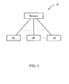
- FIG. 1 is a schematic diagram of a wireless communication system 10.
- the wireless communication system 10 is composed of a network and a plurality of mobile devices.
- the wireless communication system 10 can be a Long-Term Evolution (LTE) system, LTE advanced (LTE-A) system, or any other similar mobile communication system.
- the network may be an E-UTRAN comprising a plurality of eNBs.
- the UEs can be devices such as mobile phones, computer systems, etc. This terminology will be used throughout the application for ease of reference; however, this should not be construed as limiting the invention to any one particular type of network.
- the network and the UE can be seen as a transmitter or receiver according to transmission direction, e.g., for uplink (UL), the UE is the transmitter and the network is the receiver, and for downlink (DL), the network is the transmitter and the UE is the receiver.
- UL uplink
- DL downlink
- FIG. 2 is a schematic diagram of a UE and multiple cells under an eNB in the wireless communication system 10.
- the UE communicates with Cell 1 to Cell N, and each cell can transmit and receive on two or more component carriers since the wireless communication system 10 is an LTE-A system supporting carrier aggregation.
- the UE establishes links with Cell 1 by component carriers CC1, CC2, and CC3, and establishes links with Cell 2 by the component carriers CC1 and CC2, and so on.
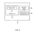
- Fig. 3 is a schematic diagram of a communication device 20 according to an example.
- the communication device 20 can be the mobile devices shown in Fig. 1 and may include a processor means 200 such as a microprocessor or ASIC, a memory unit 210, and a communication interfacing unit 220.
- the memory unit 210 may be any data storage device that can store program code 214, for access by the processing means 200. Examples of the memory unit 210 include but are not limited to a subscriber identity module (SIM), read-only memory (ROM), random-access memory (RAM), CD-ROMs, magnetic tapes, hard disks, and optical data storage devices.
- SIM subscriber identity module
- ROM read-only memory
- RAM random-access memory
- CD-ROMs compact disc-read-only memory
- magnetic tapes magnetic tapes
- hard disks hard disks
- optical data storage devices optical data storage devices.
- the communication interfacing unit 220 is preferably a radio transceiver and can exchange wireless signals with the network according to processing results of the processing
- FIG. 4 is a flowchart of an exemplary process 40.
- the process 40 is utilized in the MAC layer of a UE in the wireless communication system 10, for handling a request for requesting UL-SCH resource under carrier aggregation of component carriers CC1-CCn.
- the process 40 can be compiled into the program code 214 and includes the following steps:
- the UE MAC layer receives UL data from a higher layer, the radio resource control (RRC) layer.
- RRC radio resource control
- the UE MAC layer triggers a request to request UL-SCH resource according to Step 404, and instructs the lower layer, the physical (PHY) layer, to transmit the request to the eNB according to Step 406.
- the process 40 implies that even if multiple component carriers are configured with the UE, the UE may still use only one component carrier, or may use all of the component carriers to transmit the request for requesting UL-SCH resource.
- the request indicates an SR or a random access preamble, and which one is triggered depends on whether the PUCCH resource is configured on each component carrier.
- Step 404 and Step 406 may be implemented by several alternatives as follows.
- the first alternative is that when the PUCCH resource is configured on an anchor component carrier, which is a component carrier that the UE can detect and camp on in an radio resource control (RRC) idle mode, of the component carriers CC1-CCn in the current TTI, the UE MAC layer triggers the SR on the anchor component carrier (Step 404), and instructs the physical layer to transmit the SR on the anchor component carrier (Step 406). In this case, the SR is not triggered and transmitted on the component carriers other than the anchor component carrier.
- RRC radio resource control
- the second alternative is that when the PUCCH resource is configured on the each of the component carriers CC1-CCn in the current TTI, the UE MAC layer triggers the SR on each of the component carriers CC1-CCn (Step 404), and instructs the physical layer to transmit the SR on each of the component carriers CC1-CCn (Step 406). In other words, the SR is triggered and transmitted on all of the component carriers CC1-CCn.
- the third alternative is that when no PUCCH resource is configured on the component carriers CC1-CCn in the current TTI, a physical random access channel (PRACH) resource is used instead.
- PRACH physical random access channel
- the UE MAC layer triggers the random access preamble on an anchor component carrier (Step 404), and instructs the physical layer to transmit the random access preamble on the PRACH resource on the anchor component carrier (Step 406).
- the fourth alternative is that when no PUCCH resource is configured on the component carriers CC1-CCn in the current TTI, the UE MAC layer triggers the random access preamble on each of the component carriers CC1-CCn (Step 404), and instructs the physical layer to transmit the random access preamble on the PRACH resource on each of the component carriers CC1-CCn (Step 406). Similar to the SR transmission, the random access preamble may be also triggered and transmitted on the anchor carrier, or on all of the component carriers CC1-CCn.
- the eNB After the eNB receives the SR or the random access preamble, the eNB assigns an UL grant for new transmission to the UE, and therefore the UE has UL-SCH resource to transmit UL data. Solutions to a pending SR under carrier aggregation are further provided. One is to keep the SR on each of the component carriers CC1-CCn pending until new UL-SCH resource is granted by an UL grant assigned on any one of the component carriers CC1-CCn, which is usually the first UL grant. In other words, after the SR is transmitted by the PUCCH resource on a component carrier, the transmitted SR is considered pending until new UL-SCH resource is granted by an UL grant on any one of the component carriers CC1-CCn. The pending SRs on the component carriers CC1-CCn are cancelled by the first UL-SCH resource allocated on any component carrier.
- the other is to keep the SR on one of the component carriers CC1-CCn pending until new UL-SCH resource is granted by the first UL grant which is assigned on the same component carrier.
- the triggered SRs on the component carrier CC1 and on the component carrier CC2 remain pending; the pending SR on the component carrier CC2 is only cancelled by the first UL grant on the component carrier CC2, and is not cancelled by the first UL grant on the component carrier CC 1 even if the component carrier CC 1 is the anchor component carrier.
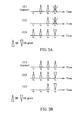
- FIG. 5A and FIG. 5B are timing diagrams illustrating how the SR is triggered, transmitted, and cancelled under three component carriers CC1-CC3 according to the second alternative of the process 40 and the above solutions for pending SR, where the anchor component carrier is CC1.
- the SR is triggered and transmitted on the component carriers CC1-CC3 at different time; when the first new UL-SCH resource is granted by the first UL grant on the component carrier CC3 at a time point t 4 , pending SRs on the component carriers CC1-CC3 are cancelled.
- FIG. 5A the SR is triggered and transmitted on the component carriers CC1-CC3 at different time; when the first new UL-SCH resource is granted by the first UL grant on the component carrier CC3 at a time point t 4 , pending SRs on the component carriers CC1-CC3 are cancelled.
- the SR is triggered and transmitted on the component carriers CC1-CC3 at different time; when UL-SCH resources are allocated by UL grants on the component carriers CC2 and CC3 at a time point t 4 , the SR on the component carrier CC 1 still remains pending and is not cancelled.
- the pending SR on each of the component carriers CC1-CC3 is cancelled only by the UL grant on the same carrier.
- FIG. 6 is a schematic diagram of an exemplary communication device 60.
- the communication device 60 is a system implementation of the process 40 in FIG. 4 , and is installed in the UE.
- the communication device 60 comprises a receiving unit 600, a triggering unit 602, a first control unit 604, and a second control unit 606.
- the receiving unit 600 is utilized for performing Step 402 of receiving UL data.
- the triggering unit 602 is coupled to the receiving unit 600, and is utilized for performing Step 404.
- the first control unit 604 is coupled to the triggering unit 602, and is utilized for performing Step 406.
- the second control unit 606 is coupled to the triggering unit 602, and is utilized for selectively performing the solutions for pending SR cancellation. Please refer to the process 40 for understanding the communication device 60, which is not repeated herein.
- FIG. 7 is a flowchart of an exemplary process 70.
- the process 70 is utilized in the UE MAC layer for handling BSR under carrier aggregation of the component carriers CC1-CCn.
- the process 70 can be compiled into the program code 214 and includes the following steps:
- the BSR on different component carrier indicates the same information that is the size of UL data available in a UE transmission buffer.
- Different triggering events cause BSRs of different types, such as regular BSR and periodic BSR, which are specified following the current MAC specification and are not given herein.
- the UE MAC layer detects whether a trigger event occurs so as to decide to trigger a BSR or not.
- the UE MAC layer triggers a BSR on at least one of the component carriers CC1-CCn, and instructs the physical layer to report the BSR according to at least one UL grant for new transmission, i.e. to report the BSR on UL-SCH resources allocated by the at least one UL grant.
- the process 70 implies that even if multiple component carriers are configured with the UE, the UE may use only one component carrier, or may use all of the component carriers to report the BSR. Please note that, a condition that the BSR can be triggered on one component carrier but reported on another component carrier may be considered. Based on the above reasons, Step 704 and Step 706 may be implemented by several alternatives as follows by which component carrier the BSR is triggered and reported on.
- the first alternative is that the UE MAC layer triggers the BSR only on the anchor component carrier of the component carriers CC1-CCn when the triggering event occurs (Step 704), and certainly, the UE MAC layer instructs the physical layer to report the BSR according to the first UL grant for new transmission assigned on the anchor component carrier (Step 706).
- the second alternative is that the UE MAC layer triggers the BSR on each of the component carriers CC1-CCn (Step 704), and instructs the physical layer to report the BSR according to the first UL grant for new transmission only on the anchor component carrier (Step 706).
- the third alternative is that the UE MAC layer triggers the BSR on each of the component carriers CC1-CCn (Step 704), and instructs the physical layer to report the BSR according to the first UL grant assigned on any one of the component carriers CC1-CCn, which is not necessary to be the anchor component (Step 706).
- the BSR can be triggered on all of the component carriers CC1-CC3 but reported on the component carrier CC2 or CC3.
- the UE MAC layer instructs the physical layer to report the BSR according to an UL grant which has a larger size among these UL grants on the same TTI.
- the BSR is reported on a component carrier where the first UL grant has a large size than other UL grants on other component carriers.
- the fourth alternative is that the UE MAC layer triggers the BSR on each of the component carriers CC1-CCn (Step 704), and instructs the physical layer to report the BSR triggered on the each of the component carriers CC1-CCn according to the first uplink grant assigned on the same component carrier (Step 706). That is, the BSR is triggered and reported independently. For example, when three component carriers CC1-CC3 are configured with the UE, where the component carrier CC1 is the anchor component carrier, the BSR triggered on the component carrier CC1 is only reported according to the first UL grant assigned on the component carrier CC1, and the BSR triggered on the component carrier CC2 is only reported according to the first UL grant assigned on the component carrier CC2, and so on.
- a pending BSR trigger on the component carrier CC1 is cancelled only when the BSR is reported on the component carrier CC1, and is not cancelled when the BSR is reported by the component carrier CC2.
- FIG. 8A-8D are timing diagrams illustrating how the BSR is triggered, reported, and cancelled under three component carriers CC1-CC3 according to aforementioned four different solutions of the process 70 and solutions to pending BSRs, where the anchor component carrier is the component carrier CC1.
- FIG. 8A illustrates the first solution that the BSR is triggered and reported only on the anchor component carrier CC1.
- FIG. 8A illustrates the first solution that the BSR is triggered and reported only on the anchor component carrier CC1.
- 8B illustrates the second solution that the BSR is triggered on each component carrier but reported only on the anchor component carrier CC1; even though the first UL grant is assigned on the component carrier CC2 at a time point t 2 , and the first UL-SCH resource is on the component CC2 at a time point t 3 , the BSR is reported until at a time point t 4 when the first UL-SCH resource is on the anchor component carrier CC1; pending BSR triggers on the component carriers CC2 and CC3 are cancelled once the BSR is reported at the time point t d .
- FIG. 8C illustrates the third solution that the BSR is triggered on each component carrier and is reported according to the first UL grant on any one of the component carriers CC1-CC3.
- the BSR is reported according to the first UL grant assigned on the component carrier CC2 at a time point t 2 ; once the BSR is reported at a time point t 3 , pending BSR triggers on the component carriers CC1-CC3 are cancelled.
- FIG. 8D illustrates the fourth solution that the BSR is triggered on each component carrier, and is reported and cancelled on the same component carrier. As can be seen in FIG.
- FIG. 9 is a schematic diagram of an exemplary communication device 90.
- the communication device 90 is a system implementation of the process 70 in FIG. 7 installed in the UE.
- the communication device 90 comprises a detecting unit 900, a triggering unit 902, a first control unit 904, and a second control unit 906.
- the detecting unit 900 is utilized for performing Step 702 of detecting whether a triggering event occurs.
- the triggering unit 902 is coupled to the detecting unit 900, and is utilized for performing Step 704, for triggering a BSR on the anchor component carrier or on all of the component carriers.
- the first control unit 904 is coupled to the triggering unit 902, and is utilized for performing Step 706 of instructing the physical layer to report the BSR according to the first UL grant, which may be on the anchor component carrier, any one of the component carriers, or each of the component carriers.
- the second control unit 906 is coupled to the triggering unit 902, and is utilized for performing solutions for cancelling all pending BSR triggers once the BSR is reported, or cancelling a pending BSR trigger on a component carrier the same as which component carrier the BSR is reported on. Operation of the communication device 90 is detailed described in the process 70, and is not repeated herein.
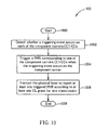
- FIG. 10 is a flowchart of an exemplary process 100.
- the process 100 is utilized in the UE MAC layer for handling PHR under carrier aggregation of the component carriers CC1-CCn.
- the process 100 can be compiled into the program code 214 and includes the following steps:
- a PHR indicates the power headroom level of a corresponding component carrier.
- PHRs denoted as P1-Pn, on the component carriers CC1-CCn may be triggered at different time since the transmit power of each component carrier is estimated independently. Triggering events that cause PHR are specified in the current MAC specification and are not given herein.
- the UE MAC layer detects whether a triggering event occurs on each of the component carriers in a current TTI, and triggers a PHR Pi which indicates the power headroom level on one of the component carriers CC1-CCn, called a component carrier CCi, when detecting the triggering event occurs on the component carrier CCi.
- Step 1006 when there is at least one triggered PHR waiting to be reported, the UE instructs the physical layer to report the at least one triggered PHR according to at least one UL grant for new transmission by using Step 1006, which implies that the triggered PHR(s) may be reported on one or more than one component carrier. For this reason, Step 1006 may be implemented by several alternatives as follows.
- the first alternative is that the UE MAC layer instructs the physical layer to report the at least one triggered PHR (which may not be as many as the component carriers CC1-CCn) according the first UL grant assigned only on the anchor component carrier. In other words, all of the triggered PHRs are reported on an UL-SCH resource allocated by the first UL grant assigned on the anchor component carrier.
- the second alternative is that the UE MAC layer instructs the physical layer to report the at least one triggered PHR according the first UL grant assigned on any one of the component carriers CC1-CCn, which is not limited to be the anchor component carrier.
- the third alternative is that the UE MAC layer instructs the physical layer to report each of the PHRs P1-Pn corresponding to the component CC1-CCn according to the first uplink grant assigned on the same component carrier, i.e., the PHRs are reported independently. For example, when the PHR P2 indicating the power headroom level of the component carrier CC2 is triggered, the PHR P2 is reported only on an UL-SCH resource allocated by the first UL grant assigned on the component carrier CC2.
- Step 1006 two different solutions to handle pending PHR triggers are further provided.
- One is used after performing the first or the second alternative of Step 1006, which is that once all of the at least one triggered PHR is reported, the UE MAC layer cancels all pending PHR triggers on used component carriers where the at least one triggered PHR is already reported; PHR triggers for those PHRs not yet reported remain pending.
- the other is used after the third alternative of Step 1006, which is that the UE MAC layer cancels a pending PHR trigger on one of the component carriers CC1-CCn once a PHR corresponding to the same component carrier is reported, i.e. the PHR triggers are cancelled independently.
- FIG. 11A-11C are timing diagrams illustrating how PHRs are triggered, reported, and cancelled under four component carriers CC1-CC4 according to aforementioned three different alternatives of the process 100 and solutions to pending PHRs, where the anchor component carrier is CC 1.
- PHRs corresponding to the component carriers CC1-CC4 are denoted as P1-P4.
- FIG. 11A illustrates the first solution. As shown in FIG. 11A , the PHRs P1-P4 are triggered at different times, respectively.
- the first UL grant is assigned on the component carrier CC2 at a time point t 3 , but the PHRs P1-P3 are reported by an UL-SCH resource at a time point t s , which is allocated by the first UL grant assigned on the anchor component carrier CC 1 at a time point t 4 , and the PHR P4 is not reported.
- Pending PHR triggers on the component carriers CC1-CC3 are cancelled once the PHRs P1-P3 are reported, while a PHR trigger on the component carrier CC4 remains pending.
- FIG. 11B illustrates the second solution.
- the PHRs P1-P4 are triggered at different times, and the PHRs P1-P4 are reported by an UL-SCH resource on the component carrier CC2 where the first UL grant is assigned.
- the PHRs P1-P4 are reported at a time point t 4 , all pending PHR triggers on the component carriers CC 1-CC4 are cancelled.
- FIG. 11C illustrates the third solution in which the PHR report and cancellation are independent. In FIG. 11C , the PHRs P1-P3 are triggered at different times.
- the first two bits of a PHR MAC control element are reserved bits.
- the two reserved bit can be used to indicate which component carrier a reported PHR corresponds to, and thereby the eNB can recognize the component carrier related to the reported PHR when the eNB receives a PHR MAC control element.
- FIG. 12 is a schematic diagram of an exemplary communication device 120.
- the communication device 120 is a system implementation of the process 100 in FIG. 10 installed in the UE.
- the communication device 120 comprises a detecting unit 1200, a triggering unit 1202, a first control unit 1204, and a second control unit 1206.
- the detecting unit 1200 is utilized for performing Step 1002.
- the triggering unit 1202 is coupled to the detecting unit 1200, and is utilized for performing Step 1004.
- the first control unit 1204 is coupled to the triggering unit 1202, and is utilized for selectively performing the three alternatives of Step 1006 for reporting the triggered PHRs.
- the first control unit 1204 is also utilized for indicating which component carrier a reported PHR corresponds to by using the reserved bits in the PHR MAC control element.
- the second control unit 1206 is coupled to the triggering unit 1202, and is utilized for selectively performing two solutions of handling pending PHR triggers after the triggered PHRs are reported. Operation of the communication device 120 is detailed described in the process 100, and is not repeated herein.
- steps of the processes 40, 70, 100 including suggested steps can be realized by means that could be hardware, firmware known as a combination of a hardware device and computer instructions and data that reside as read-only software on the hardware device, or an electronic system.
- hardware can include analog, digital and mixed circuits known as microcircuit, microchip, or silicon chip.
- the electronic system can include system on chip (SOC), system in package (Sip), computer on module (COM), and the communication device 20.
- SOC system on chip
- Sip system in package
- COM computer on module
- the exemplary methods and systems of handling uplink information including SR, BSR, and PHR for the UE supporting carrier aggregation are provided, so that the UE reports SR, BSR, and PHR more efficiently.
- the UE can receive UL resource as soon as possible, and therefore UL transmission is improved.
Claims (2)
- Procédé de gestion d'informations de liaison montante dans un regroupement de porteuses pour une couche de commande d'accès au support, en abrégé MAC, d'un équipement d'utilisateur dans un système de communications sans fil (10), le procédé comprenant les étapes suivantes :détecter si un événement de déclenchement a lieu sur chacune d'une pluralité de porteuses de composantes (1002) ;déclencher un rapport de marge de puissance, en abrégé PHR, correspondant à l'une de la pluralité de porteuses de composantes lorsque l'événement de déclenchement a lieu sur la porteuse de composantes (1004) ; etdonner instruction à une couche inférieure de l'équipement d'utilisateur de rapporter au moins un PHR déclenché conformément à un accord de liaison montante attribué sur une composante d'ancrage de la pluralité de porteuses de composantes, un accord de liaison montante attribué sur l'une quelconque de la pluralité de porteuses de composantes, ou un accord de liaison montante attribué sur la même porteuse de composantes,indiquer une porteuse de composante à laquelle correspond un PHR rapporté, par bits reservés d'un élément de commande MAC PHR.
- Dispositif de communication (120) d'un système de communication sans fil pour gérer des informations de liaison montante dans un regroupement de porteuses, le dispositif de communication (120) comprenant :un module de détection (1200) pour détecter si un événement de déclenchement a lieu sur chacune d'une pluralité de porteuses de composantes (1002) ;un module de déclenchement (1202) couplé au module de détection (1200) pour déclencher un rapport de marge de puissance, en abrégé PHR, correspondant à l'une de la pluralité de porteuses de composantes lorsque l'événement de déclenchement a lieu sur la porteuse de composantes (1004) ; etun premier module de commande (1204) couplé au module de déclenchement (1202) pour donner instruction à une couche inférieure du dispositif de communication (120) de rapporter au moins un PHR déclenché conformément à un accord de liaison montante attribué à une composante d'ancrage de la pluralité de porteuses de composantes, un accord de liaison montante attribué à l'une quelconque de la pluralité de porteuses de composantes, ou un accord de liaison montante attribué à la même porteuse de composante, et pour indiquer une porteuse de composantes à laquelle correspond un PHR rapporté, par bits reservés d'un élément de commande MAC PHR.
Applications Claiming Priority (1)
| Application Number | Priority Date | Filing Date | Title |
|---|---|---|---|
| US16035009P | 2009-03-16 | 2009-03-16 |
Publications (3)
| Publication Number | Publication Date |
|---|---|
| EP2230875A2 EP2230875A2 (fr) | 2010-09-22 |
| EP2230875A3 EP2230875A3 (fr) | 2010-09-29 |
| EP2230875B1 true EP2230875B1 (fr) | 2012-10-03 |
Family
ID=42233799
Family Applications (1)
| Application Number | Title | Priority Date | Filing Date |
|---|---|---|---|
| EP10002776A Active EP2230875B1 (fr) | 2009-03-16 | 2010-03-16 | Verfahren und Vorrichtung zur Handhabung von Uplink-Informationen mittels Carrier-Aggregation in einem drahtlosen Kommunikationssystem |
Country Status (4)
| Country | Link |
|---|---|
| US (1) | US8422387B2 (fr) |
| EP (1) | EP2230875B1 (fr) |
| CN (1) | CN101841844A (fr) |
| TW (1) | TWI439160B (fr) |
Families Citing this family (51)
| Publication number | Priority date | Publication date | Assignee | Title |
|---|---|---|---|---|
| EP2634950B1 (fr) * | 2009-03-23 | 2016-11-30 | Innovative Sonic Limited | Procédé et appareil pour rapporter le marge de puissance |
| CN101873577B (zh) * | 2009-04-27 | 2017-03-22 | 电信科学技术研究院 | 通知ue变更成员载波监听的方法、系统及装置 |
| JP5667167B2 (ja) | 2009-05-05 | 2015-02-12 | テレフオンアクチーボラゲット エル エム エリクソン(パブル) | スケジューリング要求のトリガのハンドリング |
| CA2763448C (fr) | 2009-05-22 | 2016-09-06 | Research In Motion Limited | Compte rendu de marge de puissance pour agregation de porteuse |
| CN101932087A (zh) * | 2009-06-19 | 2010-12-29 | 大唐移动通信设备有限公司 | 一种功率余量的上报方法、装置和系统 |
| KR101797491B1 (ko) | 2009-12-02 | 2017-11-15 | 엘지전자 주식회사 | 이종망을 지원하는 무선 통신 시스템에서 간섭 완화 방법 및 장치 |
| EP2512198B1 (fr) * | 2009-12-31 | 2015-06-17 | Huawei Technologies Co., Ltd. | Procédé et appareil permettant une configuration de ressources basées sur la contention |
| TWI459839B (zh) | 2010-04-02 | 2014-11-01 | Mediatek Inc | 管理多成分載波、緩存器狀態報告以及功率餘裕回報方法 |
| AU2010350535B2 (en) * | 2010-04-09 | 2014-07-24 | Nokia Solutions And Networks Oy | Signalling report transmission in carrier aggregation |
| US8582551B2 (en) * | 2010-05-26 | 2013-11-12 | Intel Corporation | Device, system and method of wireless communication over non-contiguous channels |
| WO2012002684A2 (fr) | 2010-06-28 | 2012-01-05 | Samsung Electronics Co., Ltd. | Procédé et appareil pour rapporter une puissance de transmission maximale dans une communication sans fil |
| KR101740366B1 (ko) * | 2010-06-28 | 2017-05-29 | 삼성전자주식회사 | 이동 통신 시스템에서 역방향 최대 전송 전력을 보고하는 방법 및 장치 |
| CN102014506B (zh) * | 2010-07-13 | 2012-08-29 | 华为技术有限公司 | 一种触发终端发送测量参考信号的方法和基站 |
| US8954106B2 (en) | 2010-08-10 | 2015-02-10 | Samsung Electronics Co., Ltd. | Method and apparatus for configuring power headroom information in mobile communication system supporting carrier aggregation |
| US9526077B2 (en) | 2010-08-10 | 2016-12-20 | Samsung Electronics Co., Ltd. | Method and apparatus for reporting power headroom information in mobile communication system supporting carrier aggregation |
| US9344977B2 (en) | 2010-08-10 | 2016-05-17 | Samsung Electronics Co., Ltd. | Method and apparatus for reporting power headroom information in mobile communication system supporting carrier aggregation |
| EP2606617B1 (fr) * | 2010-08-16 | 2018-09-19 | Nokia Solutions and Networks Oy | Transmission de signaux de référence |
| KR20120019073A (ko) * | 2010-08-24 | 2012-03-06 | 주식회사 팬택 | 다중 요소 반송파 시스템에서 잉여전력에 관한 정보의 전송장치 및 방법 |
| CN102118786B (zh) | 2010-09-29 | 2015-07-22 | 电信科学技术研究院 | 一种载波聚合系统下phr的处理方法和设备 |
| US8798663B2 (en) * | 2010-10-01 | 2014-08-05 | Acer Incorporated | Method of performing power headroom reporting and communication device thereof |
| US10728859B2 (en) | 2010-10-12 | 2020-07-28 | Samsung Electronics Co., Ltd. | Method and apparatus for determining maximum transmission power per carrier in mobile communication system supporting carrier aggregation |
| US9055544B2 (en) * | 2010-11-02 | 2015-06-09 | Alcatel Lucent | Methods of setting maximum output power for user equipment and reporting power headroom, and the user equipment |
| US9144038B2 (en) | 2010-11-05 | 2015-09-22 | Samsung Electronics Co., Ltd. | Method and apparatus for calculating power headroom in carrier aggregation mobile communication system |
| US9185665B2 (en) * | 2010-11-05 | 2015-11-10 | Samsung Electronics Co., Ltd. | Power headroom report method and apparatus for mobile communication system supporting carrier aggregation |
| KR101954185B1 (ko) * | 2010-11-05 | 2019-06-03 | 삼성전자 주식회사 | Carrier Aggregation 이동통신 시스템에서 단말이 Power Headroom을 보고하는 방법 및 장치 |
| US9055565B2 (en) | 2010-11-05 | 2015-06-09 | Samsung Electronics Co., Ltd. | Method and device for activating secondary carrier in wireless communication system for using carrier aggregation technique |
| US8737333B2 (en) * | 2010-11-08 | 2014-05-27 | Acer Incorporated | Method of power reporting and communication device thereof |
| CN102469607B (zh) * | 2010-11-09 | 2014-01-22 | 上海贝尔股份有限公司 | 上行探测参考信号的触发和传输方法及其设备 |
| JP5541369B2 (ja) | 2010-12-10 | 2014-07-09 | 富士通株式会社 | 無線通信システム、受信装置、送信装置および無線通信方法 |
| WO2012096502A2 (fr) | 2011-01-11 | 2012-07-19 | Samsung Electronics Co., Ltd. | Procédé d'activation/de désactivation de porteuse secondaire et appareil pour système de communication mobile qui supporte une agrégation de porteuses |
| KR101763751B1 (ko) | 2011-01-11 | 2017-08-02 | 삼성전자 주식회사 | 반송파 집적 기술을 사용하는 무선통신시스템에서 부차반송파의 활성화 및 비활성화 방법 및 장치 |
| EP2684410A4 (fr) * | 2011-03-07 | 2014-08-20 | Intel Corp | Communications groupées de machine à machine |
| CN102761953B (zh) * | 2011-04-29 | 2014-08-13 | 普天信息技术研究院有限公司 | 上行定时提前量的配置方法 |
| CN102970761A (zh) * | 2011-09-01 | 2013-03-13 | 华为技术有限公司 | 数据发送方法和用户设备 |
| US9525526B2 (en) | 2012-02-02 | 2016-12-20 | Nokia Solutions And Networks Oy | Signaling of uplink scheduling information in case of carrier aggregation |
| JP5744809B2 (ja) * | 2012-09-05 | 2015-07-08 | 株式会社Nttドコモ | 移動通信方法、無線基地局及び移動局 |
| ES2885401T3 (es) | 2012-12-24 | 2021-12-13 | Innovative Sonic Corp | Métodos y aparatos de mejora en celdas pequeñas en un sistema de comunicación inalámbrica |
| KR101692657B1 (ko) * | 2013-01-11 | 2017-01-03 | 엘지전자 주식회사 | 버퍼 상태를 보고하기 위한 방법 및 이를 위한 통신 장치 |
| US20150373744A1 (en) * | 2013-03-04 | 2015-12-24 | Nokia Technologies Oy | Synchronized physical layer reconfiguration among user equipment, macrocell, and small cell in macrocell-assisted small cell deployments |
| EP2975899B1 (fr) * | 2013-03-14 | 2019-02-13 | Sharp Kabushiki Kaisha | Appareil de terminal, appareil de station de base, système de communication, procédé de communication et circuit intégré |
| CN111031573B (zh) | 2013-05-17 | 2023-04-18 | 寰发股份有限公司 | 上报bsr的方法以及用户设备 |
| KR102123434B1 (ko) | 2013-08-09 | 2020-06-17 | 삼성전자 주식회사 | 셀룰러 이동 통신 시스템에서 스케쥴링 요청 방법 및 장치 |
| US9210725B2 (en) * | 2013-08-30 | 2015-12-08 | Qualcomm Incorporated | Method and apparatus for improving uplink performance at a user equipment |
| CN106506127B (zh) | 2015-09-06 | 2021-03-16 | 中兴通讯股份有限公司 | 一种传输信息的方法和装置 |
| CN105407524B (zh) * | 2015-10-30 | 2020-07-24 | 上海华为技术有限公司 | Phr的发送方法和用户终端 |
| CN107734625A (zh) * | 2016-08-12 | 2018-02-23 | 夏普株式会社 | 发射机功率余量计算方法及其用户设备 |
| AU2016424804B2 (en) * | 2016-09-30 | 2020-11-05 | Huawei Technologies Co., Ltd. | Data processing method, terminal and base station |
| CN107959559A (zh) * | 2016-10-18 | 2018-04-24 | 工业和信息化部电信研究院 | 一种上行控制信道的设计方法和装置 |
| MX2020002877A (es) * | 2017-09-21 | 2020-07-22 | Guangdong Oppo Mobile Telecommunications Corp Ltd | Metodo de informe del estado del bufer, terminal y un medio de almacenamiento informatico. |
| US10271351B1 (en) * | 2017-11-29 | 2019-04-23 | Google Llc | User equipment grant procedure for uplink carrier aggregation |
| KR20200017780A (ko) * | 2018-08-09 | 2020-02-19 | 삼성전자주식회사 | 무선 통신 시스템에서 상향링크 데이터 보고 및 제어 채널의 동기화를 위한 장치 및 방법 |
Family Cites Families (4)
| Publication number | Priority date | Publication date | Assignee | Title |
|---|---|---|---|---|
| US8169953B2 (en) | 2005-05-17 | 2012-05-01 | Qualcomm Incorporated | Method and apparatus for wireless multi-carrier communications |
| US8223708B2 (en) * | 2008-06-10 | 2012-07-17 | Innovative Sonic Limited | Method and apparatus for handling scheduling information report |
| EP2415314A1 (fr) * | 2009-04-03 | 2012-02-08 | Telefonaktiebolaget LM Ericsson (publ) | Adaptation de liaison montante au niveau de l'équipement utilisateur |
| KR101762610B1 (ko) * | 2010-11-05 | 2017-08-04 | 삼성전자주식회사 | 이동 통신 시스템에서 역방향 스케줄링 및 그를 위한 정보 전송 방법 및 장치 |
-
2010
- 2010-03-16 US US12/724,429 patent/US8422387B2/en active Active
- 2010-03-16 EP EP10002776A patent/EP2230875B1/fr active Active
- 2010-03-16 CN CN201010147614A patent/CN101841844A/zh active Pending
- 2010-03-16 TW TW099107673A patent/TWI439160B/zh active
Also Published As
| Publication number | Publication date |
|---|---|
| EP2230875A2 (fr) | 2010-09-22 |
| EP2230875A3 (fr) | 2010-09-29 |
| US8422387B2 (en) | 2013-04-16 |
| US20100232385A1 (en) | 2010-09-16 |
| CN101841844A (zh) | 2010-09-22 |
| TW201036477A (en) | 2010-10-01 |
| TWI439160B (zh) | 2014-05-21 |
Similar Documents
| Publication | Publication Date | Title |
|---|---|---|
| EP2230875B1 (fr) | Verfahren und Vorrichtung zur Handhabung von Uplink-Informationen mittels Carrier-Aggregation in einem drahtlosen Kommunikationssystem | |
| US11470639B2 (en) | Method for transmitting and receiving uplink signal in wireless communication system supporting unlicensed band, and apparatus supporting same | |
| US10123312B2 (en) | Random access method and apparatus of UE in mobile communication system | |
| EP3205039B1 (fr) | Techniques de transmission d'un signal de référence de sondage ou de demande de planification sur une bande de spectre de radiofréquences sans licence | |
| EP3742864B1 (fr) | Procédé et appareil d'envoi/réception de données à l'aide d'une pluralité de porteuses dans un système de communication mobile | |
| EP2822333B1 (fr) | Procédé et dispositif d'améliorations de petites cellules dans un système de communication sans fil | |
| US9930596B2 (en) | Method and apparatus for controlling small data transmission on the uplink | |
| EP3923498B1 (fr) | Procédé et dispositif sans fil de bande étroite pour déterminer de transmettre ou non une demande de planification | |
| EP2849357B1 (fr) | Procédé et appareil pour transmettre et recevoir des données à l'aide d'une pluralité de porteuses dans un système de communication mobile | |
| EP2230870B1 (fr) | Procédé de gestion de la fonction d'alignement temporel de plusieurs porteurs de composants et dispositif de communication associé | |
| EP2393334B1 (fr) | Procédé d'exécution de transmission de liaison montante et dispositif de communication associé | |
| EP2854443A1 (fr) | Procédé et dispositif d'émission et de réception de données dans un système de communication mobile | |
| US20140112276A1 (en) | Method and apparatus for performing a random access process | |
| EP2557885A1 (fr) | Procédé de gestion de procédure d'accès aléatoire associée à la cellule de désactivation | |
| US20110103332A1 (en) | Method and apparatus to trigger a random access procedure for carrier aggregration in a wireless communication network | |
| EP3681059B1 (fr) | Procédé de transmission de liaison montante dans une bande sans licence et dispositif l'utilisant | |
| US9386579B2 (en) | Method and apparatus of controlling cell activation in a wireless communication system | |
| EP2809017A1 (fr) | Procédé et appareil pour groupage TTI (intervalle de temps de transmission) pour des améliorations de petites cellules dans un système de communication sans fil | |
| EP2418895B1 (fr) | Procédé de gestion de rapports de marge de puissance de la liaison montante avec agrégation de porteuses et dispositif de communication correspondant | |
| CN109076519B (zh) | 蜂窝通信系统中调度传输的方法和装置 |
Legal Events
| Date | Code | Title | Description |
|---|---|---|---|
| PUAI | Public reference made under article 153(3) epc to a published international application that has entered the european phase |
Free format text: ORIGINAL CODE: 0009012 |
|
| PUAL | Search report despatched |
Free format text: ORIGINAL CODE: 0009013 |
|
| 17P | Request for examination filed |
Effective date: 20100316 |
|
| AK | Designated contracting states |
Kind code of ref document: A2 Designated state(s): AT BE BG CH CY CZ DE DK EE ES FI FR GB GR HR HU IE IS IT LI LT LU LV MC MK MT NL NO PL PT RO SE SI SK SM TR |
|
| AX | Request for extension of the european patent |
Extension state: AL BA ME RS |
|
| AK | Designated contracting states |
Kind code of ref document: A3 Designated state(s): AT BE BG CH CY CZ DE DK EE ES FI FR GB GR HR HU IE IS IT LI LT LU LV MC MK MT NL NO PL PT RO SE SI SK SM TR |
|
| AX | Request for extension of the european patent |
Extension state: AL BA ME RS |
|
| GRAP | Despatch of communication of intention to grant a patent |
Free format text: ORIGINAL CODE: EPIDOSNIGR1 |
|
| RIC1 | Information provided on ipc code assigned before grant |
Ipc: H04B 7/26 20060101ALI20110513BHEP Ipc: H04W 74/02 20090101AFI20110513BHEP |
|
| GRAS | Grant fee paid |
Free format text: ORIGINAL CODE: EPIDOSNIGR3 |
|
| GRAJ | Information related to disapproval of communication of intention to grant by the applicant or resumption of examination proceedings by the epo deleted |
Free format text: ORIGINAL CODE: EPIDOSDIGR1 |
|
| GRAS | Grant fee paid |
Free format text: ORIGINAL CODE: EPIDOSNIGR3 |
|
| 17Q | First examination report despatched |
Effective date: 20111118 |
|
| GRAP | Despatch of communication of intention to grant a patent |
Free format text: ORIGINAL CODE: EPIDOSNIGR1 |
|
| GRAS | Grant fee paid |
Free format text: ORIGINAL CODE: EPIDOSNIGR3 |
|
| GRAA | (expected) grant |
Free format text: ORIGINAL CODE: 0009210 |
|
| AK | Designated contracting states |
Kind code of ref document: B1 Designated state(s): AT BE BG CH CY CZ DE DK EE ES FI FR GB GR HR HU IE IS IT LI LT LU LV MC MK MT NL NO PL PT RO SE SI SK SM TR |
|
| REG | Reference to a national code |
Ref country code: GB Ref legal event code: FG4D |
|
| REG | Reference to a national code |
Ref country code: AT Ref legal event code: REF Ref document number: 578514 Country of ref document: AT Kind code of ref document: T Effective date: 20121015 Ref country code: CH Ref legal event code: EP |
|
| REG | Reference to a national code |
Ref country code: IE Ref legal event code: FG4D |
|
| REG | Reference to a national code |
Ref country code: DE Ref legal event code: R096 Ref document number: 602010003001 Country of ref document: DE Effective date: 20121129 |
|
| REG | Reference to a national code |
Ref country code: NL Ref legal event code: T3 |
|
| REG | Reference to a national code |
Ref country code: AT Ref legal event code: MK05 Ref document number: 578514 Country of ref document: AT Kind code of ref document: T Effective date: 20121003 |
|
| PG25 | Lapsed in a contracting state [announced via postgrant information from national office to epo] |
Ref country code: SI Free format text: LAPSE BECAUSE OF FAILURE TO SUBMIT A TRANSLATION OF THE DESCRIPTION OR TO PAY THE FEE WITHIN THE PRESCRIBED TIME-LIMIT Effective date: 20121003 |
|
| REG | Reference to a national code |
Ref country code: LT Ref legal event code: MG4D |
|
| PG25 | Lapsed in a contracting state [announced via postgrant information from national office to epo] |
Ref country code: ES Free format text: LAPSE BECAUSE OF FAILURE TO SUBMIT A TRANSLATION OF THE DESCRIPTION OR TO PAY THE FEE WITHIN THE PRESCRIBED TIME-LIMIT Effective date: 20130114 Ref country code: IS Free format text: LAPSE BECAUSE OF FAILURE TO SUBMIT A TRANSLATION OF THE DESCRIPTION OR TO PAY THE FEE WITHIN THE PRESCRIBED TIME-LIMIT Effective date: 20130203 Ref country code: LT Free format text: LAPSE BECAUSE OF FAILURE TO SUBMIT A TRANSLATION OF THE DESCRIPTION OR TO PAY THE FEE WITHIN THE PRESCRIBED TIME-LIMIT Effective date: 20121003 Ref country code: HR Free format text: LAPSE BECAUSE OF FAILURE TO SUBMIT A TRANSLATION OF THE DESCRIPTION OR TO PAY THE FEE WITHIN THE PRESCRIBED TIME-LIMIT Effective date: 20121003 Ref country code: NO Free format text: LAPSE BECAUSE OF FAILURE TO SUBMIT A TRANSLATION OF THE DESCRIPTION OR TO PAY THE FEE WITHIN THE PRESCRIBED TIME-LIMIT Effective date: 20130103 Ref country code: SE Free format text: LAPSE BECAUSE OF FAILURE TO SUBMIT A TRANSLATION OF THE DESCRIPTION OR TO PAY THE FEE WITHIN THE PRESCRIBED TIME-LIMIT Effective date: 20121003 Ref country code: FI Free format text: LAPSE BECAUSE OF FAILURE TO SUBMIT A TRANSLATION OF THE DESCRIPTION OR TO PAY THE FEE WITHIN THE PRESCRIBED TIME-LIMIT Effective date: 20121003 |
|
| PG25 | Lapsed in a contracting state [announced via postgrant information from national office to epo] |
Ref country code: PL Free format text: LAPSE BECAUSE OF FAILURE TO SUBMIT A TRANSLATION OF THE DESCRIPTION OR TO PAY THE FEE WITHIN THE PRESCRIBED TIME-LIMIT Effective date: 20121003 Ref country code: GR Free format text: LAPSE BECAUSE OF FAILURE TO SUBMIT A TRANSLATION OF THE DESCRIPTION OR TO PAY THE FEE WITHIN THE PRESCRIBED TIME-LIMIT Effective date: 20130104 Ref country code: PT Free format text: LAPSE BECAUSE OF FAILURE TO SUBMIT A TRANSLATION OF THE DESCRIPTION OR TO PAY THE FEE WITHIN THE PRESCRIBED TIME-LIMIT Effective date: 20130204 Ref country code: LV Free format text: LAPSE BECAUSE OF FAILURE TO SUBMIT A TRANSLATION OF THE DESCRIPTION OR TO PAY THE FEE WITHIN THE PRESCRIBED TIME-LIMIT Effective date: 20121003 Ref country code: BE Free format text: LAPSE BECAUSE OF FAILURE TO SUBMIT A TRANSLATION OF THE DESCRIPTION OR TO PAY THE FEE WITHIN THE PRESCRIBED TIME-LIMIT Effective date: 20121003 |
|
| PG25 | Lapsed in a contracting state [announced via postgrant information from national office to epo] |
Ref country code: AT Free format text: LAPSE BECAUSE OF FAILURE TO SUBMIT A TRANSLATION OF THE DESCRIPTION OR TO PAY THE FEE WITHIN THE PRESCRIBED TIME-LIMIT Effective date: 20121003 |
|
| PG25 | Lapsed in a contracting state [announced via postgrant information from national office to epo] |
Ref country code: CZ Free format text: LAPSE BECAUSE OF FAILURE TO SUBMIT A TRANSLATION OF THE DESCRIPTION OR TO PAY THE FEE WITHIN THE PRESCRIBED TIME-LIMIT Effective date: 20121003 Ref country code: BG Free format text: LAPSE BECAUSE OF FAILURE TO SUBMIT A TRANSLATION OF THE DESCRIPTION OR TO PAY THE FEE WITHIN THE PRESCRIBED TIME-LIMIT Effective date: 20130103 Ref country code: SK Free format text: LAPSE BECAUSE OF FAILURE TO SUBMIT A TRANSLATION OF THE DESCRIPTION OR TO PAY THE FEE WITHIN THE PRESCRIBED TIME-LIMIT Effective date: 20121003 Ref country code: EE Free format text: LAPSE BECAUSE OF FAILURE TO SUBMIT A TRANSLATION OF THE DESCRIPTION OR TO PAY THE FEE WITHIN THE PRESCRIBED TIME-LIMIT Effective date: 20121003 Ref country code: DK Free format text: LAPSE BECAUSE OF FAILURE TO SUBMIT A TRANSLATION OF THE DESCRIPTION OR TO PAY THE FEE WITHIN THE PRESCRIBED TIME-LIMIT Effective date: 20121003 |
|
| PLBE | No opposition filed within time limit |
Free format text: ORIGINAL CODE: 0009261 |
|
| STAA | Information on the status of an ep patent application or granted ep patent |
Free format text: STATUS: NO OPPOSITION FILED WITHIN TIME LIMIT |
|
| PG25 | Lapsed in a contracting state [announced via postgrant information from national office to epo] |
Ref country code: IT Free format text: LAPSE BECAUSE OF FAILURE TO SUBMIT A TRANSLATION OF THE DESCRIPTION OR TO PAY THE FEE WITHIN THE PRESCRIBED TIME-LIMIT Effective date: 20121003 Ref country code: RO Free format text: LAPSE BECAUSE OF FAILURE TO SUBMIT A TRANSLATION OF THE DESCRIPTION OR TO PAY THE FEE WITHIN THE PRESCRIBED TIME-LIMIT Effective date: 20121003 |
|
| 26N | No opposition filed |
Effective date: 20130704 |
|
| PG25 | Lapsed in a contracting state [announced via postgrant information from national office to epo] |
Ref country code: MC Free format text: LAPSE BECAUSE OF NON-PAYMENT OF DUE FEES Effective date: 20130331 |
|
| REG | Reference to a national code |
Ref country code: DE Ref legal event code: R097 Ref document number: 602010003001 Country of ref document: DE Effective date: 20130704 |
|
| PG25 | Lapsed in a contracting state [announced via postgrant information from national office to epo] |
Ref country code: CY Free format text: LAPSE BECAUSE OF FAILURE TO SUBMIT A TRANSLATION OF THE DESCRIPTION OR TO PAY THE FEE WITHIN THE PRESCRIBED TIME-LIMIT Effective date: 20121003 |
|
| REG | Reference to a national code |
Ref country code: FR Ref legal event code: ST Effective date: 20131129 |
|
| REG | Reference to a national code |
Ref country code: IE Ref legal event code: MM4A |
|
| PG25 | Lapsed in a contracting state [announced via postgrant information from national office to epo] |
Ref country code: FR Free format text: LAPSE BECAUSE OF NON-PAYMENT OF DUE FEES Effective date: 20130402 Ref country code: IE Free format text: LAPSE BECAUSE OF NON-PAYMENT OF DUE FEES Effective date: 20130316 |
|
| PG25 | Lapsed in a contracting state [announced via postgrant information from national office to epo] |
Ref country code: MT Free format text: LAPSE BECAUSE OF FAILURE TO SUBMIT A TRANSLATION OF THE DESCRIPTION OR TO PAY THE FEE WITHIN THE PRESCRIBED TIME-LIMIT Effective date: 20121003 |
|
| REG | Reference to a national code |
Ref country code: CH Ref legal event code: PL |
|
| GBPC | Gb: european patent ceased through non-payment of renewal fee |
Effective date: 20140316 |
|
| PG25 | Lapsed in a contracting state [announced via postgrant information from national office to epo] |
Ref country code: CH Free format text: LAPSE BECAUSE OF NON-PAYMENT OF DUE FEES Effective date: 20140331 Ref country code: LI Free format text: LAPSE BECAUSE OF NON-PAYMENT OF DUE FEES Effective date: 20140331 Ref country code: GB Free format text: LAPSE BECAUSE OF NON-PAYMENT OF DUE FEES Effective date: 20140316 |
|
| PG25 | Lapsed in a contracting state [announced via postgrant information from national office to epo] |
Ref country code: SM Free format text: LAPSE BECAUSE OF FAILURE TO SUBMIT A TRANSLATION OF THE DESCRIPTION OR TO PAY THE FEE WITHIN THE PRESCRIBED TIME-LIMIT Effective date: 20121003 |
|
| PG25 | Lapsed in a contracting state [announced via postgrant information from national office to epo] |
Ref country code: TR Free format text: LAPSE BECAUSE OF FAILURE TO SUBMIT A TRANSLATION OF THE DESCRIPTION OR TO PAY THE FEE WITHIN THE PRESCRIBED TIME-LIMIT Effective date: 20121003 |
|
| PG25 | Lapsed in a contracting state [announced via postgrant information from national office to epo] |
Ref country code: LU Free format text: LAPSE BECAUSE OF NON-PAYMENT OF DUE FEES Effective date: 20130316 Ref country code: HU Free format text: LAPSE BECAUSE OF FAILURE TO SUBMIT A TRANSLATION OF THE DESCRIPTION OR TO PAY THE FEE WITHIN THE PRESCRIBED TIME-LIMIT; INVALID AB INITIO Effective date: 20100316 Ref country code: MK Free format text: LAPSE BECAUSE OF FAILURE TO SUBMIT A TRANSLATION OF THE DESCRIPTION OR TO PAY THE FEE WITHIN THE PRESCRIBED TIME-LIMIT Effective date: 20121003 |
|
| PGFP | Annual fee paid to national office [announced via postgrant information from national office to epo] |
Ref country code: DE Payment date: 20230117 Year of fee payment: 14 |
|
| PGFP | Annual fee paid to national office [announced via postgrant information from national office to epo] |
Ref country code: NL Payment date: 20230113 Year of fee payment: 14 |
|
| P01 | Opt-out of the competence of the unified patent court (upc) registered |
Effective date: 20230602 |
|
| PGFP | Annual fee paid to national office [announced via postgrant information from national office to epo] |
Ref country code: NL Payment date: 20240108 Year of fee payment: 15 |