EP2230737A1 - Wiring harness, use of a protective tape and method of forming a wiring harness - Google Patents
Wiring harness, use of a protective tape and method of forming a wiring harness Download PDFInfo
- Publication number
- EP2230737A1 EP2230737A1 EP10001859A EP10001859A EP2230737A1 EP 2230737 A1 EP2230737 A1 EP 2230737A1 EP 10001859 A EP10001859 A EP 10001859A EP 10001859 A EP10001859 A EP 10001859A EP 2230737 A1 EP2230737 A1 EP 2230737A1
- Authority
- EP
- European Patent Office
- Prior art keywords
- protective tape
- cable bundle
- thickness
- wiring harness
- glue
- Prior art date
- Legal status (The legal status is an assumption and is not a legal conclusion. Google has not performed a legal analysis and makes no representation as to the accuracy of the status listed.)
- Withdrawn
Links
Images


Classifications
-
- H—ELECTRICITY
- H02—GENERATION; CONVERSION OR DISTRIBUTION OF ELECTRIC POWER
- H02G—INSTALLATION OF ELECTRIC CABLES OR LINES, OR OF COMBINED OPTICAL AND ELECTRIC CABLES OR LINES
- H02G3/00—Installations of electric cables or lines or protective tubing therefor in or on buildings, equivalent structures or vehicles
- H02G3/02—Details
- H02G3/04—Protective tubing or conduits, e.g. cable ladders or cable troughs
- H02G3/0462—Tubings, i.e. having a closed section
- H02G3/0481—Tubings, i.e. having a closed section with a circular cross-section
-
- C—CHEMISTRY; METALLURGY
- C09—DYES; PAINTS; POLISHES; NATURAL RESINS; ADHESIVES; COMPOSITIONS NOT OTHERWISE PROVIDED FOR; APPLICATIONS OF MATERIALS NOT OTHERWISE PROVIDED FOR
- C09J—ADHESIVES; NON-MECHANICAL ASPECTS OF ADHESIVE PROCESSES IN GENERAL; ADHESIVE PROCESSES NOT PROVIDED FOR ELSEWHERE; USE OF MATERIALS AS ADHESIVES
- C09J7/00—Adhesives in the form of films or foils
- C09J7/20—Adhesives in the form of films or foils characterised by their carriers
- C09J7/29—Laminated material
-
- C—CHEMISTRY; METALLURGY
- C09—DYES; PAINTS; POLISHES; NATURAL RESINS; ADHESIVES; COMPOSITIONS NOT OTHERWISE PROVIDED FOR; APPLICATIONS OF MATERIALS NOT OTHERWISE PROVIDED FOR
- C09J—ADHESIVES; NON-MECHANICAL ASPECTS OF ADHESIVE PROCESSES IN GENERAL; ADHESIVE PROCESSES NOT PROVIDED FOR ELSEWHERE; USE OF MATERIALS AS ADHESIVES
- C09J2203/00—Applications of adhesives in processes or use of adhesives in the form of films or foils
- C09J2203/302—Applications of adhesives in processes or use of adhesives in the form of films or foils for bundling cables
-
- C—CHEMISTRY; METALLURGY
- C09—DYES; PAINTS; POLISHES; NATURAL RESINS; ADHESIVES; COMPOSITIONS NOT OTHERWISE PROVIDED FOR; APPLICATIONS OF MATERIALS NOT OTHERWISE PROVIDED FOR
- C09J—ADHESIVES; NON-MECHANICAL ASPECTS OF ADHESIVE PROCESSES IN GENERAL; ADHESIVE PROCESSES NOT PROVIDED FOR ELSEWHERE; USE OF MATERIALS AS ADHESIVES
- C09J2400/00—Presence of inorganic and organic materials
- C09J2400/20—Presence of organic materials
- C09J2400/26—Presence of textile or fabric
- C09J2400/263—Presence of textile or fabric in the substrate
-
- Y—GENERAL TAGGING OF NEW TECHNOLOGICAL DEVELOPMENTS; GENERAL TAGGING OF CROSS-SECTIONAL TECHNOLOGIES SPANNING OVER SEVERAL SECTIONS OF THE IPC; TECHNICAL SUBJECTS COVERED BY FORMER USPC CROSS-REFERENCE ART COLLECTIONS [XRACs] AND DIGESTS
- Y10—TECHNICAL SUBJECTS COVERED BY FORMER USPC
- Y10T—TECHNICAL SUBJECTS COVERED BY FORMER US CLASSIFICATION
- Y10T29/00—Metal working
- Y10T29/49—Method of mechanical manufacture
- Y10T29/49002—Electrical device making
- Y10T29/49227—Insulator making
Definitions
- the present invention relates to a wiring harness provided with a protective member, to a use of a tape for a wiring harness and to a method of forming or producing a wiring harness.
- a corrugated tube as a protective member is known as a measure for protecting a cable bundle constituting a wiring harness to be installed in an automotive vehicle or the like (see Japanese Unexamined Patent Publication No. 2000-353432 ).
- a specific mounting structure is such that, after cables are bundled into a cable bundle by winding a tape (inner taping), the cable bundle is accommodated into a corrugated tube while a slit formed in a longitudinal direction is being opened and a tape is wound around the outer circumferential surface of the corrugated tube (outer taping) to prevent the slit from being opened.
- an accommodation rate of the cable bundle in the corrugated tube is suppressed, for example, to 80 % to suppress the opening of the corrugated tube when the wiring harness is bent or on another occasion, which has made the wiring harness bulky to hinder space saving.
- the present invention was developed in view of the above situation and an object thereof is to allow providing a wiring harness provided with a protective member capable of realizing a cost reduction and space saving while fulfilling a function of protecting a cable bundle.
- the present invention is directed to a wiring harness, wherein a protective tape having an adhesive layer formed on the underside of a laminated base material formed by bonding two fabrics made of knitted fabric(s) and/or woven fabric(s) by a glue and/or adhesive is at least partly wound around a cable bundle.
- the base material has a three-layer structure by bonding the two fabrics by the glue and/or adhesive, a load is mainly distributed in the two fabrics to relax a stress in the case of receiving the load from outside, whereby the protective tape can be said to be difficult to abrade, i.e. have good abrasion resistance.
- the protective tape can be easily cut by hand, i.e. have a good hand cutting property.
- the protective tape can be mounted only by being at least partly wound around the outer circumferential surface of the cable bundle and has a good hand cutting property, it can be easily cut by hand, with the result that an operation of mounting the protective tape can be efficiently performed. In other words, a time required for a protective member mounting operation can be shortened and the number of parts can be reduced, wherefore production cost can be drastically reduced.
- the prevent invention may have the following constructions.
- a protective tape to be at least partly wound around a cable bundle of a wiring harness, wherein the protective tape has an adhesive layer formed on the underside of a laminated base material formed by bonding two fabrics made of knitted fabric(s) and/or woven fabric(s) by a glue and/or adhesive.
- the prevent invention may have the following constructions.
- a method of forming a wiring harness comprising the following steps:
- the prevent invention may have the following constructions.
- a wiring harness provided with a protective member capable of realizing a cost reduction and space saving while fulfilling a function of protecting a cable bundle.
- the first embodiment roughly has such a structure that a protective tape 20 as a protective member is wound around a cable bundle 10 forming part of a wiring harness.
- the cable bundle 10 is such that a plurality of insulated cables 11 and/or shielded cables are bundled as shown in FIG. 3 .
- the protective tape 20 comprises or is composed of a base material 21 and an adhesive layer 24 formed on the underside of the base material 21 to be held in contact with the outer circumferential surface of the cable bundle 10.
- the base material 21 has a three-layer structure formed by bonding two knitted fabrics 22 by a glue or adhesive 23.
- the "knitted fabric” is such that either warps or wefts are continuous strings of loops and the others are inserted through these loops.
- a "woven fabric” is a fabric formed by vertically or orthogonally intersecting warps and wefts.
- a polyamide glue is illustrated as the glue 23 and preferably applied in dots (in points) or on discontinuous areas having a small extension (such as not greater than about 4 mm2) between the two knitted fabrics 22.
- the glue 23 may be applied in a substantially regular pattern such as a lattice.
- An acrylic adhesive or a rubber adhesive can be cited as examples of the glue forming the adhesive layer 24.
- the thicknesses of the respective layers are set such that the thickness t1 of the knitted fabric 22 on the top side and that t3 of the knitted fabric 22 on the under side are below about 1.0 mm, thickness t2 of the glue 23 is about 0.05 to about 1.0 mm and thickness t4 of the adhesive layer 24 is about 0.05 to about 1.0 mm and the total thickness is equal to or below about 2.0 mm. In this embodiment, the total thickness is set at 1.0 mm.
- the width of the protective tape 20 is set below about 100 mm and, for example, selected to be 25 mm.
- the protective tape 20 having such width (25 mm) and thickness (1.0 mm) is prepared in the form of a so-called roll 30 by being wound around a core element such as a paper core tube 31 as shown in FIG. 2 .
- the protective tape 20 Upon protecting the cable bundle 10 constituting a part of the wiring harness, the protective tape 20 at least partly is (preferably manually) wound around this cable bundle 10.
- the protective tape 20 is spirally wound around the outer circumferential surface of the cable bundle with lateral ends or portions thereof overlapped while being dispensed from the roll 30 (as a preferred core element) as shown in FIG. 3 , and the adhesive layer 24 on the underside substantially is bonded to the outer circumferential surface of the cable bundle 10.
- about 1/4 of the entire width is overlapped (1/4 overlap) or about half the entire width is overlapped (half overlap).
- the protective tape 20 After the protective tape 20 is wound around over a specified (predetermined or predeterminable) area of the cable bundle 10, the protective tape 20 needs to be cut or separated.
- the base material 21 of the protective tape 20 is mainly composed of the knitted fabrics 22, the protective tape 20 can be easily cut or separated by hand, i.e. has a good hand cutting property.
- the protective tape 20 of this embodiment can be said to have good abrasion resistance if a hole is made to such an extent that the cable bundle 10 inside is exposed to the outside when the protective tape 20 is subjected to an external load.
- the protective tape 20 is thought to be difficult to abrade since the base material 21 of the protective tape 20 has the three-layer structure by bonding the two knitted fabrics 22 by the glue 23 and a load is mainly distributed in the two knitted fabrics 22, i.e. a stress is relaxed, in the case of receiving the load from outside. Further, since the glue 23 preferably is applied in dots and a clearance is formed between the two knitted fabrics 22, a load distribution function of the knitted fabrics 22 is better fulfilled.
- an abrasion resistance tester for automotive low-voltage cables
- JIS for automotive low-voltage cables
- a sample 100 is sandwiched between a pair of upper and lower metallic sandwiching portions 102, 103 while being wound around and boned to the outer circumferential surface of a conductor 101 made of an aluminum tube, and an endless abrasive tape (JIS R6251 based article) is arranged to be able to travel between the lower sandwiching portion 103 and the sample 100.
- Conductive portions 105 are provided at specified intervals (150 mm) on the abrasive tape 104, the lower sandwiching portion 103 and the conductor 101 are connected by a conductive line 106 and a conduction measuring unit 107 is provided at an intermediate position of the conductive line 106.
- the abrasive tape 104 With a load K (45 gf) exerted to the upper sandwiching portion 102, the abrasive tape 104 is caused to travel at a specified speed (1500 mm/min). As the abrasive tape 104 travels, the sample 100 is gradually abraded to eventually have a hole made therein. Then, one conductive portion 105 of the abrasive tape 104 comes into contact with the conductor 101 via the hole and a current flows in the conduction line 106. When this is detected by the conduction measuring unit 107, the abrasive tape 104 is stopped.
- the travel of the abrasive tape 104 stops when the hole is made in the sample 100 after the travel is started.
- the traveling time of the abrasive tape 104 becomes longer, i.e. as the traveling distance becomes longer, more difficulty to make a hole in the sample 100, i.e. better abrasion resistance can be evaluated.
- the traveling distance of the abrasive tape 104 indicating abrasion resistance was confirmed to have reached 100 to 200 mm as shown in FIG. 5 .
- the test result was obtained which indicated that the protective tape 20 of this embodiment had good abrasion resistance similar to the corrugated tube as a proven protective member for a wiring harness.
- the protective tape 20 of this embodiment has a good sound deadening property since it has the three-layer structure by bonding the two knitted fabrics 22 by the glue 23 and the glue 23 preferably is applied in dots to form the clearance between the two knitted fabrics 22.
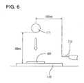
- the test relating to hitting sound was such that a sample 100 was placed on a test plate 110 made of a stainless steel plate (can also be a PP (polypropylene) plate or a PE (polyethylene) plate) having a thickness of 2 mm, an iron ball of 100 g was freely fallen on the sample 100 from a position at a height of 30 mm, hitting sound generated at that time was measured by a measuring unit 112 arranged at a position which is slightly above the test plate 110 and at a horizontal distance of 100 mm from the fallen position of the iron ball 111 as shown in FIG. 6 .
- a test plate 110 made of a stainless steel plate (can also be a PP (polypropylene) plate or a PE (polyethylene) plate) having a thickness of 2 mm
- an iron ball of 100 g was freely fallen on the sample 100 from a position at a height of 30 mm
- hitting sound generated at that time was measured by a measuring unit 112 arranged at a position which is slightly above the
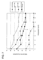
- a test result of the protective tape 20 of this embodiment is as shown by a characteristic line X of a graph of FIG. 7 and the hitting sound is 40 dB or below in an audible region (6 to 20 kHz). This indicates a sound deadening property equal to or better than that of a soft tape (urethane foam tape) having a thickness of 4 mm proven to have a good sound deadening property against hitting sound.
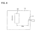
- the test relating to friction sound was such that the sample 100 was manually slid in an arrow direction at a speed of about 20 mm/sec at a specified position on a test plate 115 made of a stainless steel plate (can also be a PP (polypropylene) plate or a PE (polyethylene) plate) having a thickness of 2 mm, and friction sound generated at that time was measured by the measuring unit 112 arranged at a position which is slightly above the test plate 115 and at a horizontal distance of 30 mm from the sliding position of the sample 100 as shown in FIG. 8 .
- a test plate 115 made of a stainless steel plate (can also be a PP (polypropylene) plate or a PE (polyethylene) plate) having a thickness of 2 mm
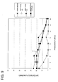
- a test result of the protective tape 20 of this embodiment is as shown by a characteristic line Y of a graph of FIG. 9 and the friction sound is 20 dB or below in the audible region (6 to 20 kHz). This indicates a sound deadening property equal to or better than that of soft tapes (urethane foam tapes) having thicknesses of 2 mm and 4 mm proven to have a good sound deadening property against friction sound.
- the protective tape 20 of this embodiment has good flexibility since the base material 21 of the protective tape 20 has the three-layer structure as described above and the glue 23 preferably is applied in dots to form the clearance between the two knitted fabrics 22. Thus, even if the outer circumferential surface of the cable bundle 10 is uneven or the cable bundle 10 is bent, the protective tape 20 can be closely wound around the outer circumferential surface of the cable bundle 10.
- the wiring harness formed by winding the protective tape 20 according to this embodiment around the cable bundle 10 as described above can obtain the following numerous advantages.
- the protective tape 20 itself has abrasion resistance equivalent to that of the corrugated tube proven to be the protective member for the cable bundle 10, it can sufficiently fulfill its function of protecting the cable bundle 10.
- the protective tape 20 can be mounted only by being substantially spirally wound at least partly around the outer circumferential surface of the cable bundle 10 with the lateral edges or portions thereof overlapped while being dispensed from the roll 30. Further, since having a good hand cutting property, the protective tape 20 can be easily cut by hand also when it is cut after being wound in a specific manner. As a result, an operation of mounting the protective tape 20 as the protective member can be efficiently performed.
- the protective tape 20 preferably having a thickness of about 1.0 mm is only wound, an increase in the diameter of the wiring harness can be suppressed to a minimum level, which contributes to space saving. Weight saving can also be simultaneously realized.
- the protective tape 20 has a good sound deadening property, the generation of noise can be suppressed when the wiring harness comes into contact with or is rubbed against a surrounding device or the like due to vibration or the like.
- the protective tape 20 can be more closely wound around the outer circumferential surface of the cable bundle 10 even if the outer circumferential surface of the cable bundle 10 is uneven or the cable bundle 10 is bent.
- a protective tape 20 is composed of or comprises a three-layer base material 21 formed by bonding two knitted fabrics 22 by a glue 23 (preferably applied in dots) such that the fabrics 22 are separated from each other to form the clearance preferably having a thickness of about 0.05 to about 1.0 mm (substantially corresponding to the thickness t2 of the glue 23), and an adhesive layer 24 formed on the underside of the base material 21.
- the base material 21 has a three-layer structure, a load is mainly distributed in the two knitted fabrics 22 to relax a stress in the case of receiving the load from outside, whereby the protective tape 20 is difficult to abrade, i.e. has good abrasion resistance, and also has a good hand cutting property.
- the protective tape 20 is to be substantially spirally wound around the outer circumferential surface of at least part of a cable bundle 10 with lateral edges or portions thereof overlapped while preferably being dispensed from a roll 30, and the adhesive layer 24 on the underside is bonded to the outer circumferential surface of the cable bundle 10.
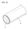
- FIG. 10 shows a second preferred embodiment of the present invention showing another mode for winding the protective tape 20.
- the protective tape 20 is wound around the outer circumferential surface of the cable bundle 10 into a cylindrical shape with the opposite lateral edges or portions thereof overlapped.
- the protective tape 20 is so placed as to substantially extend in a lengthwise direction of the cable bundle 10 while being dispensed from the roll 30 (see FIG. 2 ), and is hand-cut after extending over a specified (predetermined or predeterminable) region. Thereafter, the protective tape 20 is so wound into a cylindrical form as overlap the opposite lateral edges or portions thereof preferably by about 1/4 of the entire width, and the adhesive layer 24 on the underside is bonded to the outer circumferential surface of the cable bundle 10.
- FIG. 11 shows a third preferred embodiment of the present invention showing still another mode for winding the protective tape 20.
- the protective tape 20 is wound around the outer circumferential surface of the cable bundle 10 substantially into a cylindrical shape with the inner surfaces of the opposite lateral edges or portions thereof put or joined together.
- the protective tape 20 is so placed as to substantially extend in the lengthwise direction of the cable bundle 10 while being dispensed from the roll 30 (see FIG. 2 ), and is hand-cut after extending over a specified (predetermined or predeterminable) region. Thereafter, the protective tape 20 is wound with the inner surfaces of the opposite lateral edges thereof put or joined together or contacted, and the adhesive layer 24 on the underside is bonded to the outer circumferential surface of the cable bundle 10.
- a dimension of a part where the inner surfaces of the opposite lateral edges are put together (particularly by applying the respective adhesives layers 24 to each other) preferably is about 1/4 of the entire width of the protective tape 20.
Abstract
An object of the present invention is to provide a wiring harness provided with a protective member capable of realizing a cost reduction and space saving while fulfilling a function of protecting a cable bundle.
A protective tape 20 is composed of a three-layer base material 21 formed by bonding two knitted fabrics 22 by a glue 23 applied in dots, and an adhesive layer 24 formed on the underside of the base material 21. Since the base material 21 has a three-layer structure, a load is mainly distributed in the two knitted fabrics 22 to relax a stress in the case of receiving the load from outside, whereby the protective tape 20 is difficult to abrade, i.e. has good abrasion resistance, and also has a good hand cutting property. The protective tape 20 is spirally wound around the outer circumferential surface of a cable bundle 10 with lateral edges thereof overlapped while being dispensed from a roll 30, and the adhesive layer 24 on the underside is bonded to the outer circumferential surface of the cable bundle 10.
Description
- The present invention relates to a wiring harness provided with a protective member, to a use of a tape for a wiring harness and to a method of forming or producing a wiring harness.
- The use of a corrugated tube as a protective member is known as a measure for protecting a cable bundle constituting a wiring harness to be installed in an automotive vehicle or the like (see Japanese Unexamined Patent Publication No.
2000-353432 - In the case of using the corrugated tube as the protective member, an inner taping operation of winding the tape around the cable bundle, an operation of accommodating the cable bundle into the corrugated tube and an outer taping operation of winding the tape to prevent the opening of the corrugated tube are necessary. Many operation steps and many parts to be assembled have caused a cost increase.
- Further, in the case of using the corrugated tube, an accommodation rate of the cable bundle in the corrugated tube is suppressed, for example, to 80 % to suppress the opening of the corrugated tube when the wiring harness is bent or on another occasion, which has made the wiring harness bulky to hinder space saving.
- The present invention was developed in view of the above situation and an object thereof is to allow providing a wiring harness provided with a protective member capable of realizing a cost reduction and space saving while fulfilling a function of protecting a cable bundle.
- This object is solved according to the invention by the features of the independent claims. Preferred embodiments of the invention are subject of the dependent claims.
- The present invention is directed to a wiring harness, wherein a protective tape having an adhesive layer formed on the underside of a laminated base material formed by bonding two fabrics made of knitted fabric(s) and/or woven fabric(s) by a glue and/or adhesive is at least partly wound around a cable bundle.
- Since the base material has a three-layer structure by bonding the two fabrics by the glue and/or adhesive, a load is mainly distributed in the two fabrics to relax a stress in the case of receiving the load from outside, whereby the protective tape can be said to be difficult to abrade, i.e. have good abrasion resistance. By having the above three-layer structure, the protective tape can be easily cut by hand, i.e. have a good hand cutting property.
- By winding such a protective tape having good abrasion resistance, a function of protecting the cable bundle can be sufficiently fulfilled.
- Since the protective tape can be mounted only by being at least partly wound around the outer circumferential surface of the cable bundle and has a good hand cutting property, it can be easily cut by hand, with the result that an operation of mounting the protective tape can be efficiently performed. In other words, a time required for a protective member mounting operation can be shortened and the number of parts can be reduced, wherefore production cost can be drastically reduced.
- Since the so-called tape is merely wound, an increase in the diameter of the wiring harness is suppressed to a minimum level, which contributes to space saving and simultaneously realizes weight saving.
- The prevent invention may have the following constructions.
- (1) The glue or adhesive for bonding the two fabrics in the protective tape may be applied in dots or in a discontinuous manner.
Since the glue or adhesive is applied in dots to bond the two fabrics and a clearance is formed between the two fabrics, a load distribution function of the fabrics is better fulfilled. Further, the protective tape comes to have a good sound deadening property, and the generation of noise is suppressed when the wiring harness comes into contact with or is rubbed against a surrounding device or the like due to vibration or the like. Further, the protective tape has good flexibility and can be more closely wound around the outer circumferential surface of the cable bundle even if the outer circumferential surface of the cable bundle is uneven or the cable bundle is bent. - (2) The protective tape may be substantially spirally wound at least partly around the outer circumferential surface of the cable bundle with lateral edges thereof overlapped.
- (3) The protective tape may be wound at least partly around the outer circumferential surface of the cable bundle into a cylindrical shape with opposite lateral edges thereof overlapped.
- (4) The protective tape may be wound at least partly around the outer circumferential surface of the cable bundle into a cylindrical shape with the inner surfaces of opposite lateral edges thereof put together.
- (5) A thickness of the fabric on the top side and/or a thickness of the fabric on the under side are below about 1.0 mm, a thickness of the glue and/or adhesive may be about 0.05 to about 1.0 mm and/or a thickness of an adhesive layer is about 0.05 to about 1.0 mm,
- According to a further aspect of the invention, there is further provided a use of a protective tape to be at least partly wound around a cable bundle of a wiring harness, wherein the protective tape has an adhesive layer formed on the underside of a laminated base material formed by bonding two fabrics made of knitted fabric(s) and/or woven fabric(s) by a glue and/or adhesive.
- The prevent invention may have the following constructions.
- (1) The glue or adhesive for bonding the two fabrics in the protective tape may be applied in dots or in a discontinuous manner.
- (2) A thickness of the fabric on the top side and/or a thickness of the fabric on the under side are below about 1.0 mm, a thickness of the glue and/or adhesive is about 0.05 to about 1.0 mm and/or a thickness of an adhesive layer may be about 0.05 to about 1.0 mm,
- According to a further aspect of the invention, there is further provided a method of forming a wiring harness, in particular according to the above invention or a preferred embodiment thereof, comprising the following steps:
- providing a cable bundle
- providing a protective tape having an adhesive layer formed on the underside of a laminated base material formed by bonding two fabrics made of knitted fabric(s) and/or woven fabric(s) by a glue and/or adhesive, and
- at least partly wing the protective tape around the cable bundle.
- The prevent invention may have the following constructions.
- (1) The glue or adhesive for bonding the two fabrics in the protective tape may be applied in dots or in a discontinuous manner.
- (2) The protective tape may be substantially spirally wound around at least part of the outer circumferential surface of the cable bundle with lateral edges thereof overlapped.
- (3) The the protective tape may be wound around at least part of the outer circumferential surface of the cable bundle into a cylindrical shape with opposite lateral edges thereof overlapped.
- (4) The protective tape may be wound around at least part of the outer circumferential surface of the cable bundle into a cylindrical shape with the inner surfaces of opposite lateral edges thereof put together.
- (5) A thickness of the fabric on the top side and/or a thickness of the fabric on the under side are below about 1.0 mm, a thickness of the glue and/or adhesive is about 0.05 to about 1.0 mm and/or a thickness of an adhesive layer may be about 0.05 to about 1.0 mm,
- According to the above, there can be obtained a wiring harness provided with a protective member capable of realizing a cost reduction and space saving while fulfilling a function of protecting a cable bundle.
- These and other objects, features and advantages of the present invention will become more apparent upon reading of the following detailed description of preferred embodiments and accompanying drawings. It should be understood that even though embodiments are separately described, single features thereof may be combined to additional embodiments.
-
FIG. 1 is a section of a protection tape according to a first embodiment of the invention, -
FIG. 2 is a perspective view of a roll of the protective tape, -
FIG. 3 is a side view showing a mode for winding the protective tape around a cable bundle, -
FIG. 4 is a schematic diagram of an abrasion resistance tester, -
FIG. 5 is a graph showing a result of the test ofFIG. 4 , -
FIG. 6 is a schematic diagram of a sound deadening tester relating to hitting sound, -
FIG. 7 is a graph showing a result of the test ofFIG. 6 , -
FIG. 8 is a schematic diagram of a sound deadening tester relating to friction sound, -
FIG. 9 is a graph showing a result of the test ofFIG. 8 , -
FIG. 10 is a perspective view showing a mode for winding a protective tape around a cable bundle according to a second embodiment, and -
FIG. 11 is a perspective view showing a mode for winding a protective tape around a cable bundle according to a third embodiment. - Hereinafter, embodiments of the present invention are described with reference to the accompanying drawings.
- A first preferred embodiment of the present invention is described with reference to
FIGS. 1 to 9 . The first embodiment roughly has such a structure that aprotective tape 20 as a protective member is wound around acable bundle 10 forming part of a wiring harness. - The
cable bundle 10 is such that a plurality ofinsulated cables 11 and/or shielded cables are bundled as shown inFIG. 3 . - As shown in
FIG. 1 , theprotective tape 20 comprises or is composed of abase material 21 and anadhesive layer 24 formed on the underside of thebase material 21 to be held in contact with the outer circumferential surface of thecable bundle 10. - The
base material 21 has a three-layer structure formed by bonding two knitted fabrics 22 by a glue or adhesive 23. Here, the "knitted fabric" is such that either warps or wefts are continuous strings of loops and the others are inserted through these loops. On the contrary, a "woven fabric" is a fabric formed by vertically or orthogonally intersecting warps and wefts. - Particularly, a polyamide glue is illustrated as the glue 23 and preferably applied in dots (in points) or on discontinuous areas having a small extension (such as not greater than about 4 mm2) between the two knitted fabrics 22. The glue 23 may be applied in a substantially regular pattern such as a lattice.
- An acrylic adhesive or a rubber adhesive can be cited as examples of the glue forming the
adhesive layer 24. - The thicknesses of the respective layers are set such that the thickness t1 of the knitted fabric 22 on the top side and that t3 of the knitted fabric 22 on the under side are below about 1.0 mm, thickness t2 of the glue 23 is about 0.05 to about 1.0 mm and thickness t4 of the
adhesive layer 24 is about 0.05 to about 1.0 mm and the total thickness is equal to or below about 2.0 mm. In this embodiment, the total thickness is set at 1.0 mm. - The width of the
protective tape 20 is set below about 100 mm and, for example, selected to be 25 mm. - The
protective tape 20 having such width (25 mm) and thickness (1.0 mm) is prepared in the form of a so-calledroll 30 by being wound around a core element such as apaper core tube 31 as shown inFIG. 2 . - Upon protecting the
cable bundle 10 constituting a part of the wiring harness, theprotective tape 20 at least partly is (preferably manually) wound around thiscable bundle 10. In this embodiment, theprotective tape 20 is spirally wound around the outer circumferential surface of the cable bundle with lateral ends or portions thereof overlapped while being dispensed from the roll 30 (as a preferred core element) as shown inFIG. 3 , and theadhesive layer 24 on the underside substantially is bonded to the outer circumferential surface of thecable bundle 10. For example, about 1/4 of the entire width is overlapped (1/4 overlap) or about half the entire width is overlapped (half overlap). - After the
protective tape 20 is wound around over a specified (predetermined or predeterminable) area of thecable bundle 10, theprotective tape 20 needs to be cut or separated. Here, since thebase material 21 of theprotective tape 20 is mainly composed of the knitted fabrics 22, theprotective tape 20 can be easily cut or separated by hand, i.e. has a good hand cutting property. - Evaluation as to whether or not the
protective tape 20 wound as above is valid as the protective member for thecable bundle 10 substantially means evaluation on the abrasion resistance of theprotective tape 20 itself. Here, theprotective tape 20 of this embodiment can be said to have good abrasion resistance if a hole is made to such an extent that thecable bundle 10 inside is exposed to the outside when theprotective tape 20 is subjected to an external load. - The
protective tape 20 is thought to be difficult to abrade since thebase material 21 of theprotective tape 20 has the three-layer structure by bonding the two knitted fabrics 22 by the glue 23 and a load is mainly distributed in the two knitted fabrics 22, i.e. a stress is relaxed, in the case of receiving the load from outside. Further, since the glue 23 preferably is applied in dots and a clearance is formed between the two knitted fabrics 22, a load distribution function of the knitted fabrics 22 is better fulfilled. - The following result was obtained upon conducting a test on the abrasion resistance of the
protective tape 20 according to this embodiment. - Upon the test, an abrasion resistance tester (for automotive low-voltage cables) specified by JIS was used as shown in
FIG. 4 . In this tester, asample 100 is sandwiched between a pair of upper and lowermetallic sandwiching portions conductor 101 made of an aluminum tube, and an endless abrasive tape (JIS R6251 based article) is arranged to be able to travel between thelower sandwiching portion 103 and thesample 100.Conductive portions 105 are provided at specified intervals (150 mm) on theabrasive tape 104, thelower sandwiching portion 103 and theconductor 101 are connected by aconductive line 106 and aconduction measuring unit 107 is provided at an intermediate position of theconductive line 106. - With a load K (45 gf) exerted to the
upper sandwiching portion 102, theabrasive tape 104 is caused to travel at a specified speed (1500 mm/min). As theabrasive tape 104 travels, thesample 100 is gradually abraded to eventually have a hole made therein. Then, oneconductive portion 105 of theabrasive tape 104 comes into contact with theconductor 101 via the hole and a current flows in theconduction line 106. When this is detected by theconduction measuring unit 107, theabrasive tape 104 is stopped. - In short, the travel of the
abrasive tape 104 stops when the hole is made in thesample 100 after the travel is started. Thus, as the traveling time of theabrasive tape 104 becomes longer, i.e. as the traveling distance becomes longer, more difficulty to make a hole in thesample 100, i.e. better abrasion resistance can be evaluated. - Upon testing the
protective tape 20 of this embodiment, the traveling distance of theabrasive tape 104 indicating abrasion resistance was confirmed to have reached 100 to 200 mm as shown inFIG. 5 . - On the other hand, upon conducting the same test using a PP (polypropylene) film having a thickness of 3 mm supposing a non-flame retardant corrugated tube used as a conventional protective member, a numerical value relating to abrasion resistance was confirmed to be 100 to 200 mm.
- In other words, the test result was obtained which indicated that the
protective tape 20 of this embodiment had good abrasion resistance similar to the corrugated tube as a proven protective member for a wiring harness. - The
protective tape 20 of this embodiment has a good sound deadening property since it has the three-layer structure by bonding the two knitted fabrics 22 by the glue 23 and the glue 23 preferably is applied in dots to form the clearance between the two knitted fabrics 22. - For the evaluation of the sound deadening property, two tests, i.e. a test relating to hitting sound and a test relating to friction sound were conducted.
- The test relating to hitting sound was such that a
sample 100 was placed on atest plate 110 made of a stainless steel plate (can also be a PP (polypropylene) plate or a PE (polyethylene) plate) having a thickness of 2 mm, an iron ball of 100 g was freely fallen on thesample 100 from a position at a height of 30 mm, hitting sound generated at that time was measured by a measuringunit 112 arranged at a position which is slightly above thetest plate 110 and at a horizontal distance of 100 mm from the fallen position of theiron ball 111 as shown inFIG. 6 . - A test result of the
protective tape 20 of this embodiment is as shown by a characteristic line X of a graph ofFIG. 7 and the hitting sound is 40 dB or below in an audible region (6 to 20 kHz). This indicates a sound deadening property equal to or better than that of a soft tape (urethane foam tape) having a thickness of 4 mm proven to have a good sound deadening property against hitting sound. - The test relating to friction sound was such that the
sample 100 was manually slid in an arrow direction at a speed of about 20 mm/sec at a specified position on atest plate 115 made of a stainless steel plate (can also be a PP (polypropylene) plate or a PE (polyethylene) plate) having a thickness of 2 mm, and friction sound generated at that time was measured by the measuringunit 112 arranged at a position which is slightly above thetest plate 115 and at a horizontal distance of 30 mm from the sliding position of thesample 100 as shown inFIG. 8 . - A test result of the
protective tape 20 of this embodiment is as shown by a characteristic line Y of a graph ofFIG. 9 and the friction sound is 20 dB or below in the audible region (6 to 20 kHz). This indicates a sound deadening property equal to or better than that of soft tapes (urethane foam tapes) having thicknesses of 2 mm and 4 mm proven to have a good sound deadening property against friction sound. - The above two sound deadening tests confirmed that the
protective tape 20 of this embodiment had a good sound deadening property against both hitting sound and friction sound. - The
protective tape 20 of this embodiment has good flexibility since thebase material 21 of theprotective tape 20 has the three-layer structure as described above and the glue 23 preferably is applied in dots to form the clearance between the two knitted fabrics 22. Thus, even if the outer circumferential surface of thecable bundle 10 is uneven or thecable bundle 10 is bent, theprotective tape 20 can be closely wound around the outer circumferential surface of thecable bundle 10. - The wiring harness formed by winding the
protective tape 20 according to this embodiment around thecable bundle 10 as described above can obtain the following numerous advantages. - First of all, since the
protective tape 20 itself has abrasion resistance equivalent to that of the corrugated tube proven to be the protective member for thecable bundle 10, it can sufficiently fulfill its function of protecting thecable bundle 10. - In addition, the
protective tape 20 can be mounted only by being substantially spirally wound at least partly around the outer circumferential surface of thecable bundle 10 with the lateral edges or portions thereof overlapped while being dispensed from theroll 30. Further, since having a good hand cutting property, theprotective tape 20 can be easily cut by hand also when it is cut after being wound in a specific manner. As a result, an operation of mounting theprotective tape 20 as the protective member can be efficiently performed. - Since the
protective tape 20 preferably having a thickness of about 1.0 mm is only wound, an increase in the diameter of the wiring harness can be suppressed to a minimum level, which contributes to space saving. Weight saving can also be simultaneously realized. - Further, since the
protective tape 20 has a good sound deadening property, the generation of noise can be suppressed when the wiring harness comes into contact with or is rubbed against a surrounding device or the like due to vibration or the like. - Furthermore, since having good flexibility, the
protective tape 20 can be more closely wound around the outer circumferential surface of thecable bundle 10 even if the outer circumferential surface of thecable bundle 10 is uneven or thecable bundle 10 is bent. - Accordingly, to provide a wiring harness provided with a protective member capable of realizing a cost reduction and space saving while fulfilling a function of protecting a cable bundle, a
protective tape 20 is composed of or comprises a three-layer base material 21 formed by bonding two knitted fabrics 22 by a glue 23 (preferably applied in dots) such that the fabrics 22 are separated from each other to form the clearance preferably having a thickness of about 0.05 to about 1.0 mm (substantially corresponding to the thickness t2 of the glue 23), and anadhesive layer 24 formed on the underside of thebase material 21. Since thebase material 21 has a three-layer structure, a load is mainly distributed in the two knitted fabrics 22 to relax a stress in the case of receiving the load from outside, whereby theprotective tape 20 is difficult to abrade, i.e. has good abrasion resistance, and also has a good hand cutting property. Theprotective tape 20 is to be substantially spirally wound around the outer circumferential surface of at least part of acable bundle 10 with lateral edges or portions thereof overlapped while preferably being dispensed from aroll 30, and theadhesive layer 24 on the underside is bonded to the outer circumferential surface of thecable bundle 10. -
FIG. 10 shows a second preferred embodiment of the present invention showing another mode for winding theprotective tape 20. - In the second embodiment, the
protective tape 20 is wound around the outer circumferential surface of thecable bundle 10 into a cylindrical shape with the opposite lateral edges or portions thereof overlapped. - More specifically, the
protective tape 20 is so placed as to substantially extend in a lengthwise direction of thecable bundle 10 while being dispensed from the roll 30 (seeFIG. 2 ), and is hand-cut after extending over a specified (predetermined or predeterminable) region. Thereafter, theprotective tape 20 is so wound into a cylindrical form as overlap the opposite lateral edges or portions thereof preferably by about 1/4 of the entire width, and theadhesive layer 24 on the underside is bonded to the outer circumferential surface of thecable bundle 10. - Effects similar to the first embodiment can be obtained also for a wiring harness wound with the
protective tape 20 in the mode according to the second embodiment. -
FIG. 11 shows a third preferred embodiment of the present invention showing still another mode for winding theprotective tape 20. - In the third embodiment, the
protective tape 20 is wound around the outer circumferential surface of thecable bundle 10 substantially into a cylindrical shape with the inner surfaces of the opposite lateral edges or portions thereof put or joined together. - More specifically, the
protective tape 20 is so placed as to substantially extend in the lengthwise direction of thecable bundle 10 while being dispensed from the roll 30 (seeFIG. 2 ), and is hand-cut after extending over a specified (predetermined or predeterminable) region. Thereafter, theprotective tape 20 is wound with the inner surfaces of the opposite lateral edges thereof put or joined together or contacted, and theadhesive layer 24 on the underside is bonded to the outer circumferential surface of thecable bundle 10. A dimension of a part where the inner surfaces of the opposite lateral edges are put together (particularly by applying the respective adhesives layers 24 to each other) preferably is about 1/4 of the entire width of theprotective tape 20. - Effects similar to the first embodiment can be obtained also for a wiring harness wound with the
protective tape 20 in the mode according to the third embodiment. - The present invention is not limited to the above described and illustrated embodiments. For example, the following embodiments are also included in the technical scope of the present invention.
- (1) Although the two fabrics constituting the base material of the protective tape are both knitted fabrics in the above embodiments, a knitted fabric and a woven fabric may be combined or two fabrics may be both woven fabrics.
- (2) If the glue for bonding the two fabrics has, for example, a relatively low hardness, it may be applied over the entire surface.
- (3) An adhesive may be used instead of the glue to bond the two fabrics. A preferable adhesive is an acrylic adhesive or a rubber adhesive.
-
- 10
- cable bundle
- 20
- protective tape
- 21
- base material
- 22
- knitted fabric (fabric)
- 23
- glue
- 24
- adhesive layer
- 30
- roll
Claims (15)
- A wiring harness, wherein a protective tape (20) having an adhesive layer (24) formed on the underside of a laminated base material formed by bonding two fabrics (22) made of knitted fabric(s) and/or woven fabric(s) by a glue and/or adhesive (23) is at least partly wound around a cable bundle (10).
- A wiring harness according to claim 1, wherein the glue or adhesive (23) for bonding the two fabrics in the protective tape is applied in dots.
- A wiring harness according to claim 1 or 2, wherein the protective tape (20) is substantially spirally wound around at least part of the outer circumferential surface of the cable bundle (20) with lateral edges thereof overlapped.
- A wiring harness according to claim 1 or 2, wherein the protective tape (20) is wound around at least part of the outer circumferential surface of the cable bundle (10) into a cylindrical shape with opposite lateral edges thereof overlapped.
- A wiring harness according to claim 1 or 2, wherein the protective tape (20) is wound around at least part of the outer circumferential surface of the cable bundle (10) into a cylindrical shape with the inner surfaces of opposite lateral edges thereof put together.
- A wiring harness according to any one of the preceding claims, wherein a thickness (t1) of the fabric (22) on the top side and/or a thickness (t3) of the fabric (22) on the under side are below about 1.0 mm, a thickness (t2) of the glue and/or adhesive (23) is about 0.05 to about 1.0 mm and/or a thickness (t4) of an adhesive layer (24) is about 0.05 to about 1.0 mm,
wherein the total thickness preferably is equal to or below about 2.0 mm. - Use of a protective tape (20) to be at least partly wound around a cable bundle (10) of a wiring harness, wherein the protective tape (20) has an adhesive layer (24) formed on the underside of a laminated base material formed by bonding two fabrics (22) made of knitted fabric(s) and/or woven fabric(s) by a glue and/or adhesive (23).
- Use according to claim 7, wherein the glue or adhesive (23) for bonding the two fabrics in the protective tape is applied in dots.
- Use according to claim 7 or 8, wherein a thickness (t1) of the fabric (22) on the top side and/or a thickness (t3) of the fabric (22) on the under side are below about 1.0 mm, a thickness (t2) of the glue and/or adhesive (23) is about 0.05 to about 1.0 mm and/or a thickness (t4) of an adhesive layer (24) is about 0.05 to about 1.0 mm,
wherein the total thickness preferably is equal to or below about 2.0 mm. - A method of forming a wiring harness, comprising the following steps:providing a cable bundle (10)providing a protective tape (20) having an adhesive layer (24) formed on the underside of a laminated base material formed by bonding two fabrics (22) made of knitted fabric(s) and/or woven fabric(s) by a glue and/or adhesive (23), andat least partly wing the protective tape (20) around the cable bundle (10).
- A method according to claim 10, wherein the glue or adhesive (23) for bonding the two fabrics in the protective tape is applied in dots.
- A method according to claim 9 or 10, wherein the protective tape (20) is substantially spirally wound around at least part of the outer circumferential surface of the cable bundle (20) with lateral edges thereof overlapped.
- A method according to claim 9 or 10, wherein the protective tape (20) is wound around at least part of the outer circumferential surface of the cable bundle (10) into a cylindrical shape with opposite lateral edges thereof overlapped.
- A method according to claim 9 or 10, wherein the protective tape (20) is wound around at least part of the outer circumferential surface of the cable bundle (10) into a cylindrical shape with the inner surfaces of opposite lateral edges thereof put together.
- A wiring harness according to any one of the preceding claims 9 to 14, wherein a thickness (t1) of the fabric (22) on the top side and/or a thickness (t3) of the fabric (22) on the under side are below about 1.0 mm, a thickness (t2) of the glue and/or adhesive (23) is about 0.05 to about 1.0 mm and/or a thickness (t4) of an adhesive layer (24) is about 0.05 to about 1.0 mm,
wherein the total thickness preferably is equal to or below about 2.0 mm.
Applications Claiming Priority (1)
| Application Number | Priority Date | Filing Date | Title |
|---|---|---|---|
| JP2009068713A JP5417922B2 (en) | 2009-03-19 | 2009-03-19 | Wire harness |
Publications (1)
| Publication Number | Publication Date |
|---|---|
| EP2230737A1 true EP2230737A1 (en) | 2010-09-22 |
Family
ID=42145115
Family Applications (1)
| Application Number | Title | Priority Date | Filing Date |
|---|---|---|---|
| EP10001859A Withdrawn EP2230737A1 (en) | 2009-03-19 | 2010-02-23 | Wiring harness, use of a protective tape and method of forming a wiring harness |
Country Status (4)
| Country | Link |
|---|---|
| US (1) | US20100236827A1 (en) |
| EP (1) | EP2230737A1 (en) |
| JP (1) | JP5417922B2 (en) |
| CN (1) | CN101840750A (en) |
Cited By (5)
| Publication number | Priority date | Publication date | Assignee | Title |
|---|---|---|---|---|
| EP2722374A1 (en) * | 2012-10-17 | 2014-04-23 | Coroplast Fritz Müller GmbH & Co. KG | Extremely friction-resistant technical adhesive strip with double-layer backing |
| EP2937393A1 (en) * | 2014-04-22 | 2015-10-28 | Coroplast Fritz Müller GmbH & Co. KG | Hand-tearable fabric adhesive tape with high wear resistance and noise reduction and method for producing the same |
| EP3101459A1 (en) * | 2015-06-05 | 2016-12-07 | CCS Technology Inc. | Optical fiber cable assemblies and methods of forming the same |
| US11020931B2 (en) | 2014-04-22 | 2021-06-01 | Coroplast Fritz Müller Gmbh & Co. Kg | Manually tearable woven adhesive tape with high abrasion resistance and noise damping, and method of making same |
| WO2022104007A1 (en) * | 2020-11-12 | 2022-05-19 | Nordson Corporation | Applications of ahesive patterns for fabric bonding and fabric articles created thereby |
Families Citing this family (20)
| Publication number | Priority date | Publication date | Assignee | Title |
|---|---|---|---|---|
| CN102138262B (en) * | 2008-08-29 | 2014-12-10 | 矢崎总业株式会社 | Wire harness routing structure |
| JP5257180B2 (en) * | 2008-11-19 | 2013-08-07 | 住友電装株式会社 | Wire protection material |
| JP5722562B2 (en) * | 2010-07-21 | 2015-05-20 | 矢崎総業株式会社 | Shield member, wire harness, and wire harness manufacturing method |
| JP2012144700A (en) * | 2010-12-25 | 2012-08-02 | Nitto Denko Corp | Flat wire cover material, flat wire covered with flat wire cover material, and electrical equipment using same |
| JP5894386B2 (en) * | 2011-01-13 | 2016-03-30 | 矢崎総業株式会社 | Wire harness with clamp |
| JP5913842B2 (en) * | 2011-06-17 | 2016-04-27 | 矢崎総業株式会社 | Manufacturing method of shielded wire |
| JP5660001B2 (en) * | 2011-10-20 | 2015-01-28 | 住友電装株式会社 | Wire harness and method for manufacturing wire harness |
| JP5768702B2 (en) * | 2011-12-21 | 2015-08-26 | 住友電装株式会社 | Wire Harness |
| CN105900185B (en) * | 2014-01-10 | 2018-04-20 | 古河电气工业株式会社 | The break-resistance method of insulated electric conductor, coil and electric/electronic device and insulated electric conductor |
| CN106663508A (en) * | 2014-08-28 | 2017-05-10 | 矢崎总业株式会社 | Sheet for wiring harnesses |
| CN105490239B (en) * | 2014-09-18 | 2017-10-03 | 国家电网公司 | A kind of electric power cable cladding winding protection band |
| US10407807B2 (en) | 2014-09-24 | 2019-09-10 | Federal-Mogul Powertrain Llc | Textile sleeve with adhesive fixation layer and methods of construction and use thereof |
| JP2016152079A (en) * | 2015-02-16 | 2016-08-22 | 住友電装株式会社 | Wiring harness |
| US10554027B2 (en) | 2016-02-03 | 2020-02-04 | Electrolock, Inc. | Protective cover for cable components |
| US9716375B1 (en) | 2016-02-03 | 2017-07-25 | Electrolock, Inc. | Method of fabricating a protective cover from foil-backed fiberglass substrate |
| JP7215363B2 (en) * | 2019-07-16 | 2023-01-31 | 株式会社オートネットワーク技術研究所 | Wire Harness |
| JP7215364B2 (en) * | 2019-07-16 | 2023-01-31 | 株式会社オートネットワーク技術研究所 | Wire Harness |
| JPWO2022039046A1 (en) | 2020-08-18 | 2022-02-24 | ||
| CN116056888A (en) | 2020-08-18 | 2023-05-02 | 电化株式会社 | Bandage |
| CN113511149B (en) * | 2021-07-16 | 2022-07-15 | 深圳市骏鼎达新材料股份有限公司 | Production method of strip material self-rolling heat-setting spiral self-rolling sleeve |
Citations (4)
| Publication number | Priority date | Publication date | Assignee | Title |
|---|---|---|---|---|
| DE29823462U1 (en) | 1998-03-31 | 1999-07-29 | Haensel Verbundtechnik Gmbh & | Protective casing |
| JP2004056861A (en) | 2002-07-17 | 2004-02-19 | Three M Innovative Properties Co | Single-sided thermo-setting shaping tape |
| WO2005085379A1 (en) | 2004-03-04 | 2005-09-15 | Tesa Ag | Highly abrasionproof strip for armouring cable harnesses in motorcars |
| DE202005021453U1 (en) | 2004-03-04 | 2008-03-20 | Tesa Ag | High abrasion resistant tape for the bandaging of wire harnesses in automobiles |
Family Cites Families (15)
| Publication number | Priority date | Publication date | Assignee | Title |
|---|---|---|---|---|
| US2134771A (en) * | 1936-02-14 | 1938-11-01 | Anaconda Wire & Cable Co | Electric cable |
| JPH031596U (en) * | 1989-05-26 | 1991-01-09 | ||
| JP2532724Y2 (en) * | 1990-04-12 | 1997-04-16 | 株式会社 スリオンテック | Cloth adhesive tape for binding wire harness |
| US5490742A (en) * | 1993-06-04 | 1996-02-13 | Cronk; Tommy J. | Modular protective pipeline cover |
| US5616387A (en) * | 1993-08-31 | 1997-04-01 | Minnesota Mining And Manufacturing Company | Perforated roll of elastic wrap |
| JPH0870526A (en) * | 1994-08-29 | 1996-03-12 | Sumitomo Wiring Syst Ltd | Splice structure of wire harness |
| FR2743932B1 (en) * | 1996-01-18 | 1998-02-13 | Henri Bigot | WIRE HARNESS COVERING TOOL |
| MXPA00005828A (en) * | 1998-03-31 | 2003-07-14 | Nsel Verbundtechnik Gmbh & Co | Protective sheath. |
| JP3311672B2 (en) * | 1998-05-27 | 2002-08-05 | 株式会社スリオンテック | Cloth adhesive tape for binding wire harness |
| DE10042732A1 (en) * | 2000-08-31 | 2002-03-28 | Tesa Ag | Process for sheathing elongated goods, such as in particular cable sets with an adhesive tape |
| JP2003138231A (en) * | 2001-10-30 | 2003-05-14 | Daikin Ind Ltd | Tape or sheet for sticking nonwoven fluororesin fabric |
| US7374127B2 (en) * | 2005-01-12 | 2008-05-20 | Smart Pipe Company, Inc. | Systems and methods for making pipe liners |
| JP5085009B2 (en) * | 2005-01-31 | 2012-11-28 | 日東シンコー株式会社 | Silence tape for wire harness |
| US7530847B2 (en) * | 2006-12-08 | 2009-05-12 | Caterpillar Inc. | Impact-resistant, high-strength, braided wiring harness |
| JP5204994B2 (en) * | 2007-06-11 | 2013-06-05 | 日東電工株式会社 | Spiral type membrane element and manufacturing method thereof |
-
2009
- 2009-03-19 JP JP2009068713A patent/JP5417922B2/en not_active Expired - Fee Related
-
2010
- 2010-02-23 EP EP10001859A patent/EP2230737A1/en not_active Withdrawn
- 2010-02-24 US US12/711,730 patent/US20100236827A1/en not_active Abandoned
- 2010-03-12 CN CN201010135953A patent/CN101840750A/en active Pending
Patent Citations (4)
| Publication number | Priority date | Publication date | Assignee | Title |
|---|---|---|---|---|
| DE29823462U1 (en) | 1998-03-31 | 1999-07-29 | Haensel Verbundtechnik Gmbh & | Protective casing |
| JP2004056861A (en) | 2002-07-17 | 2004-02-19 | Three M Innovative Properties Co | Single-sided thermo-setting shaping tape |
| WO2005085379A1 (en) | 2004-03-04 | 2005-09-15 | Tesa Ag | Highly abrasionproof strip for armouring cable harnesses in motorcars |
| DE202005021453U1 (en) | 2004-03-04 | 2008-03-20 | Tesa Ag | High abrasion resistant tape for the bandaging of wire harnesses in automobiles |
Cited By (9)
| Publication number | Priority date | Publication date | Assignee | Title |
|---|---|---|---|---|
| EP2722374A1 (en) * | 2012-10-17 | 2014-04-23 | Coroplast Fritz Müller GmbH & Co. KG | Extremely friction-resistant technical adhesive strip with double-layer backing |
| WO2014060457A1 (en) * | 2012-10-17 | 2014-04-24 | Coroplast Fritz Müller Gmbh & Co. Kg | Highly abrasion-resistant technical adhesive tape with double-layer liner |
| EP2722374B1 (en) | 2012-10-17 | 2016-10-26 | Coroplast Fritz Müller GmbH & Co. KG | Extremely friction-resistant technical adhesive strip with double-layer backing |
| US10351734B2 (en) | 2012-10-17 | 2019-07-16 | Coroplast Fritz Müller Gmbh & Co. Kg | Highly abrasion-resistant technical adhesive tape with double-layer liner |
| EP2937393A1 (en) * | 2014-04-22 | 2015-10-28 | Coroplast Fritz Müller GmbH & Co. KG | Hand-tearable fabric adhesive tape with high wear resistance and noise reduction and method for producing the same |
| EP3552820A1 (en) * | 2014-04-22 | 2019-10-16 | Coroplast Fritz Müller GmbH & Co. KG | Hand-tearable fabric adhesive tape with high wear resistance and noise reduction and method for producing the same |
| US11020931B2 (en) | 2014-04-22 | 2021-06-01 | Coroplast Fritz Müller Gmbh & Co. Kg | Manually tearable woven adhesive tape with high abrasion resistance and noise damping, and method of making same |
| EP3101459A1 (en) * | 2015-06-05 | 2016-12-07 | CCS Technology Inc. | Optical fiber cable assemblies and methods of forming the same |
| WO2022104007A1 (en) * | 2020-11-12 | 2022-05-19 | Nordson Corporation | Applications of ahesive patterns for fabric bonding and fabric articles created thereby |
Also Published As
| Publication number | Publication date |
|---|---|
| JP5417922B2 (en) | 2014-02-19 |
| CN101840750A (en) | 2010-09-22 |
| JP2010225327A (en) | 2010-10-07 |
| US20100236827A1 (en) | 2010-09-23 |
Similar Documents
| Publication | Publication Date | Title |
|---|---|---|
| EP2230737A1 (en) | Wiring harness, use of a protective tape and method of forming a wiring harness | |
| US8759681B2 (en) | Wire protective member | |
| JP5424058B2 (en) | Binding tape fabric and binding tape | |
| US8815389B2 (en) | Highly abrasionproof strip for armouring cable harnesses in motorcars | |
| US9533633B2 (en) | Wire harness | |
| JP6411018B2 (en) | Wire harness assembly structure | |
| US20020098311A1 (en) | Protective sheathing | |
| JP5646835B2 (en) | Bundling tape for wire harness and bundling tape manufacturing method | |
| EP2280105A1 (en) | Fabric for binding tape, and binding tape | |
| JP7109545B2 (en) | cover for covering long articles | |
| WO2019097788A1 (en) | Wire harness arrangement structure | |
| US20130087274A1 (en) | Method for Manufacturing an Adhesive Tape, Particularly Suited for Longitudinal Wrapping of Elongated Goods, and Device for Performing the Method | |
| WO2022270324A1 (en) | Wire harness and wire harness with attached base member | |
| JP2013539345A (en) | Conduit inner duct with low friction and high strength | |
| JP5417923B2 (en) | Wire harness | |
| JP2013132205A (en) | Protective material of wire | |
| JP2016075755A (en) | Wire harness with acoustic absorbing material | |
| WO2016121468A1 (en) | Sound-absorbing material, and wiring harness with sound-absorbing material | |
| JP7184020B2 (en) | Wiring material | |
| US20220407296A1 (en) | Wiring member | |
| JP6601537B1 (en) | Wiring member fixing structure | |
| JP6325788B2 (en) | Wire harness assembly method and assembly structure | |
| EP1498260A1 (en) | Protective member for protecting electric wires | |
| JP7184019B2 (en) | Wiring material | |
| JP6784336B1 (en) | Wiring member |
Legal Events
| Date | Code | Title | Description |
|---|---|---|---|
| PUAI | Public reference made under article 153(3) epc to a published international application that has entered the european phase |
Free format text: ORIGINAL CODE: 0009012 |
|
| 17P | Request for examination filed |
Effective date: 20100304 |
|
| AK | Designated contracting states |
Kind code of ref document: A1 Designated state(s): AT BE BG CH CY CZ DE DK EE ES FI FR GB GR HR HU IE IS IT LI LT LU LV MC MK MT NL NO PL PT RO SE SI SK SM TR |
|
| AX | Request for extension of the european patent |
Extension state: AL BA RS |
|
| 17Q | First examination report despatched |
Effective date: 20140820 |
|
| STAA | Information on the status of an ep patent application or granted ep patent |
Free format text: STATUS: THE APPLICATION IS DEEMED TO BE WITHDRAWN |
|
| 18D | Application deemed to be withdrawn |
Effective date: 20150106 |