EP2230640B1 - Verfahren zum Filtern von Tiefenbildern - Google Patents
Verfahren zum Filtern von Tiefenbildern Download PDFInfo
- Publication number
- EP2230640B1 EP2230640B1 EP10002458.7A EP10002458A EP2230640B1 EP 2230640 B1 EP2230640 B1 EP 2230640B1 EP 10002458 A EP10002458 A EP 10002458A EP 2230640 B1 EP2230640 B1 EP 2230640B1
- Authority
- EP
- European Patent Office
- Prior art keywords
- depth
- image
- pixel
- filter
- median
- Prior art date
- Legal status (The legal status is an assumption and is not a legal conclusion. Google has not performed a legal analysis and makes no representation as to the accuracy of the status listed.)
- Not-in-force
Links
- 238000000034 method Methods 0.000 title claims description 29
- 238000001914 filtration Methods 0.000 title claims description 25
- 230000002146 bilateral effect Effects 0.000 claims description 14
- 238000013139 quantization Methods 0.000 claims description 3
- 238000000638 solvent extraction Methods 0.000 claims description 2
- 238000010586 diagram Methods 0.000 description 15
- 230000015572 biosynthetic process Effects 0.000 description 13
- 238000003786 synthesis reaction Methods 0.000 description 13
- 230000010339 dilation Effects 0.000 description 10
- 230000003628 erosive effect Effects 0.000 description 10
- 238000005070 sampling Methods 0.000 description 9
- 238000010422 painting Methods 0.000 description 8
- 230000003044 adaptive effect Effects 0.000 description 7
- 238000002156 mixing Methods 0.000 description 6
- 230000001186 cumulative effect Effects 0.000 description 5
- 238000007781 pre-processing Methods 0.000 description 5
- 238000005286 illumination Methods 0.000 description 4
- 238000012545 processing Methods 0.000 description 4
- 238000009877 rendering Methods 0.000 description 4
- 238000013507 mapping Methods 0.000 description 3
- 230000002123 temporal effect Effects 0.000 description 3
- 238000012935 Averaging Methods 0.000 description 2
- 230000000903 blocking effect Effects 0.000 description 2
- 230000000694 effects Effects 0.000 description 2
- 238000013459 approach Methods 0.000 description 1
- 230000015556 catabolic process Effects 0.000 description 1
- 230000001010 compromised effect Effects 0.000 description 1
- 230000007423 decrease Effects 0.000 description 1
- 238000006731 degradation reaction Methods 0.000 description 1
- 230000001419 dependent effect Effects 0.000 description 1
- 238000005516 engineering process Methods 0.000 description 1
- 238000009499 grossing Methods 0.000 description 1
- 239000000203 mixture Substances 0.000 description 1
- 238000012986 modification Methods 0.000 description 1
- 230000004048 modification Effects 0.000 description 1
- 230000000877 morphologic effect Effects 0.000 description 1
- 238000012805 post-processing Methods 0.000 description 1
- 238000001308 synthesis method Methods 0.000 description 1
- 238000013519 translation Methods 0.000 description 1
Images


Classifications
-
- G06T5/70—
-
- G—PHYSICS
- G06—COMPUTING; CALCULATING OR COUNTING
- G06T—IMAGE DATA PROCESSING OR GENERATION, IN GENERAL
- G06T2207/00—Indexing scheme for image analysis or image enhancement
- G06T2207/10—Image acquisition modality
- G06T2207/10028—Range image; Depth image; 3D point clouds
-
- G—PHYSICS
- G06—COMPUTING; CALCULATING OR COUNTING
- G06T—IMAGE DATA PROCESSING OR GENERATION, IN GENERAL
- G06T2207/00—Indexing scheme for image analysis or image enhancement
- G06T2207/20—Special algorithmic details
- G06T2207/20004—Adaptive image processing
- G06T2207/20012—Locally adaptive
-
- G—PHYSICS
- G06—COMPUTING; CALCULATING OR COUNTING
- G06T—IMAGE DATA PROCESSING OR GENERATION, IN GENERAL
- G06T2207/00—Indexing scheme for image analysis or image enhancement
- G06T2207/20—Special algorithmic details
- G06T2207/20024—Filtering details
- G06T2207/20028—Bilateral filtering
-
- G—PHYSICS
- G06—COMPUTING; CALCULATING OR COUNTING
- G06T—IMAGE DATA PROCESSING OR GENERATION, IN GENERAL
- G06T2207/00—Indexing scheme for image analysis or image enhancement
- G06T2207/20—Special algorithmic details
- G06T2207/20024—Filtering details
- G06T2207/20032—Median filtering
Definitions
- This invention relates generally to image processing, and more particularly to reconstruction filters for depth images.
- Depth images represent distances from a camera to scene elements in 3D space. Efficient encoding of depth images is important for 3D video and free view television (FTV). FTV allows user to interactively control the view and generate new virtual images of a dynamic scene from arbitrary 3D image points.
- FTV free view television
- MVC multi-image video coding
- depth images are spatially monotonous except at depth discontinuities.
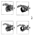
- decoding errors tend to be concentrated near depth discontinuities, and failure to preserve the depth discontinuities leads to the significantly compromised qualities of virtual images, see Figs 7(A) and 7(B) .
- Encoding a reduced resolution depth can reduce the bit rate substantially, but the loss of resolution also degrades the quality of the depth map, especially in high frequency regions such as at depth discontinuities.
- the resulting image rendering artifacts are visually annoying.
- Conventional down/up samplers either use a low-pass filter or an interpolation filter to reduce the quality degradation. That is, the conventional filters combine the depths of several pixels covered by the filter in some way for each filtered pixel. That filtering "smears" or blurs depth discontinuities because it depends on multiple depths.
- the conventional depth reconstruction are insufficient, especially for virtual image synthesis.
- GANGWAL O P ET AL "Depth map post-processing for 3D-TV CONSUMER ELECTRONICS, 2009. ICCE '09. DIGEST OF TECHNICAL PAPERS INTERNATIONAL CONFERENCE ON, IEEE, PISCATAWAY, NJ, USA, 10 January 2009 (2009-01-10) pages 1-2, XP031466993, ISBN: 978-1-4244-4701-5 , address the problem that automatically generated depth maps from stereo or monoscopie video are usually not aligned with the objects in the original image and may suffer from large area outliers. Therefore, these depth maps are post-processed y using a method to first downsample the input depth map followed by filtering and upsampling applying joint-bilateral filters to produce image aligned depth maps at full resolution.
- OH K-J ET AL "Depth reconstruction filter for depth coding" THE INSTITUTION OF ENGINEERING AND TECHNOLOGY. JOURNAL, vol. 45, no. 6, 12 March 2009 (2009-03.12), pages 305-306, XP006032799, ISSN: 1350-911X , discloses a depth reconstruction filter which consists of a frequent-close filter and a bilateral filter.
- the frequent-close filter is a nonlinear filter designed with full consideration of the characteristics of depth images to reduce the coding errors, while the bilateral filter is adapted to eliminate the remaining outliers while preserving the object boundary.
- the invention is defined by a method for filtering a depth image comprising the features of claim 1. Preferred embodiments of this method are represented in the dependent claims.
- This method for filtering a depth image wherein said depth image includes an array of pixels at locations (x, y), and wherein each pixel has a quantized depth value
- the method comprises the steps of: defining a window across the pixels in the depth image, wherein a size of the window covers a set of pixels centered at each pixel; assigning a single representative depth value from the set of pixel values in the window to the pixel to produce a processed depth image; the assigning comprising the steps of determining a median depth value for the pixels in said window, partitioning the depth values in the window into a set S low and a S high according to the median, such that the set S low includes the depth values with depths less than the medium, and the set S high includes the depth values with depths greater than the medium, determining a depth V low a depth V high with a highest frequency of occurrence in the sets S low and S high , respectively, and selecting the among V low and V high the depth value that is closer to the depth value of the pixel as the single representative depth
- the invented depth reconstruction filter includes a frequent-close filter followed by a bilateral filter.
- the frequent-close filter is non-linear, and takes into consideration characteristics of depth images to reduce coding errors, while the bilateral filter is adapted to reduce the remaining outliers, while preserving depth discontinuities.
- the embodiments of our invention take as input a video 5 that includes a sequence of texture images and a corresponding sequence of depth images.
- Some embodiments of the invention concentrated on filtering of depth images and properly reconstructing the depth images in a reduced resolution video for the purpose of virtual image synthesis, while other embodiments of the invention describe methods for performing virtual image synthesis from the sequence of texture images and the sequence of corresponding depth images.
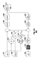
- Figure 1 shows an input video 5 including an input texture image 111 and input depth image 101 that is encoded by a texture/depth encoder 110 and passed through a channel 30 to a texture/depth decoder 120.
- the texture/depth decoder outputs a reconstructed texture image 112 and a reconstructed depth image 102, which are used as input to a view synthesis 130 to produce a synthesized virtual texture image 103.
- Fig. 2 shows a method for depth encoding 200 each input depth image 101 of the input video.
- the depth image is down sampled 10 to reduce a size of the depth image.
- the reduced resolution depth image is passed through a channel 30 to a depth decoder 40, wherein the images are reconstructed 102 by up sampling, median filtering and applying a depth reconstruction filter.
- the reconstructed depth images 102 can then be used for virtual image synthesis.
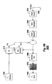
- Figure 3 shows an alternative embodiment of the invention in which the reconstruction is within the prediction loop of an encoder 301 and a decoder 302.
- Fig. 3A shows the video encoder 301, e.g., a modified H.264/AVC encoder, in greater detail.
- the encoder uses a depth reconstruction filter 370 according to embodiments of our invention.
- Input includes a current image 101 of an input video, and a reference image 105.
- Output includes an encode bitstream 103 and a reconstructed frame 104. For each frame or image of the input video, there is a corresponding depth image.
- the encoding process for the sequence of depth images is described.
- the encoding of texture is performed by conventional means.
- the current depth image is predicted either by motion estimation (ME) 310 followed by motion compensation (MC) 315, or by intra-prediction 317 according to a selector 316.
- ME motion estimation
- MC motion compensation
- intra-prediction 317 intra-prediction 317 according to a selector 316.
- a difference between the current depth image and the predicted depth image is transformed 320, quantized 330, and entropy encoded 335 to produce a bitstream 103.
- the output of the quantizer is inverse quantized 340, inverse transformed 350.
- the inverse transform is followed by a deblocking filter 360 the reconstruction filter 370 to produce the reconstructed depth image 104, which is also used by subsequent frames of the input video as a reference image 105.
- Fig. 3B shows the corresponding decoder 302.
- Input is the reference image 105 and the bitstream 103.
- Output is the reconstructed depth image 104.
- the components include an entropy decoder 375, an inverse quantization 340, an inverse transform 350, a deblocking filer 360, a reconstruction filter 370, intra-prediction 317, and motion compensation 315.
- the deblocking may be optional, unless an exact decoding is desired.
- the decoder 302 is also included in the encoder 301. This is typical of any prediction-based video standards such as MPEG-2 and H.264. This guarantees that the identical previous frames are used by both the encoder and the decoder for predicting the current image.
- Our filtering selects a single representative depth within a sliding window to recover missing or distorted depths, and to remove outliers without blurring structures in the depth images at depth discontinuities, e.g., object boundaries and edges.
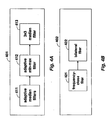
- Fig. 4A shows one embodiment of our depth reconstruction filter 401 including an adaptive median filter 411 for removing decoding errors, an adaptive min-max filter 412 for recovering depth discontinuities from a decoded image, and a 3x3 median filter 413 for eliminating any remaining errors.
- the median filter 411 is a non-linear filter that is used to reduce noise.
- the median filter does not affect the median depth significantly as a mean filter.
- the median does not cause new unrealistic pixel depths when the filter straddles a depth discontinuity.
- the stability of the median filter depends on a window size, thus we adaptively adjust the window size.
- the adaptive median filter adjusts the window size according to a quantization parameter ( QP ) used to encode the depth image because a distribution of depth decoding errors also depends on the QP .
- QP quantization parameter
- the adaptive min-max filter is the same size as the adaptive median filter.
- the filter is where A is a rectangular region and I ( x, y) is a pixel depth of the pixel at ( x , y ) in the regions, and the functions min and max return minimum and maximum depths.
- the final 3x3 median filtering corrects the outlier depths.
- Fig. 4B shows one embodiment of our depth reconstruction filter 402 which includes a frequency-close filter 421 and bilateral filter 422.
- FC frequency-close
- the frequent-close filter is a non-linear filter defined as where A represents a rectangular-shaped region of pixels, I ( x, y ) is the depth of the pixel at ( x, y ) within A, FC first and FC second are the pixel depths of the highest and the second-highest frequencies of occurrence of the depths within the regions A, respectively.
- I( x , y ) is assigned by the closer of the two representative depths FC first and FC second in the frequency-close filter.
- Fig. 6A-6C show an example 3x3 FC 601.
- the nine pixels are filtered one by one, from left-to-right and top-to-bottom in a scanning order by the moving window.
- the frequency of occurrence of each pixel depth within the window is counted, and the depth of the center pixel is changed to that of the highest or second highest frequent depth, depending on which is closer.
- the frequent-close filter has following advantages over other linear filters.
- the filter correctly filters outlier pixels.
- a single pixel that does not have a similar depth as adjacent pixels does not affect the frequent-close depth significantly.
- the frequent-close depth is the depth of only a single pixel in the neighborhood, the frequent-close filter does not cause unrealistic pixel depths when the filter straddles a depth discontinuity, e.g., an object boundary or edge.
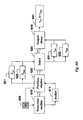
- the basic operation of the frequency-low-high filter is as follows.
- a median 611 for the pixels in a filter window W 609 is determined 610.
- the pixels are then partitioned 620 into two sets, i.e., S low 621 and S high 622 using the median, such the set S low includes the pixels with depths less than the median, and the set S high includes the pixels with depths greater than the median.
- the output 640 of the frequency-high-low filter for each center pixel in the window is the closer of v high 632 and v low 631 to the pixel depth.
- the pixels in the window W are partitioned into the low set ( S low ) and the high set group ( S high ), according to median ( W ) as W i j ⁇ ⁇ S low , if W i j ⁇ median W S high , if W i j > median W .
- v low is the pixel depth with the highest frequency of occurrence among the set of pixel intensities, which are smaller than the median depth of the window W .
- the filter correctly processes the outlier pixels.
- a single pixel that does not have a similar depth as adjacent pixels does not affect the frequent-low-high depth significantly. Because the frequent-low-high depth is the depth of one of the pixels in the neighborhood, the depth does not cause unrealistic pixel depths when the filter straddles a depth discontinuity.
- the bilateral filter is an edge-preserving filter useful for image processing. Whereas many filters are convolutions in the image domain, solely based on geometric distances among pixels, the bilateral filter also takes the pixel depths into account. The bilateral filter replaces the depths of the pixels with a weighted average of adjacent pixels. However, the weights are determined not only based on the geometric distances, but also the differences in the pixel depths. The bilateral filter removes the remaining errors around the discontinuity, preserving the depth discontinuity by means of a non-linear combination of adjacent pixel depths. This is achieved by systematically limiting the effect of pixels across depth discontinuity.
- Our bilateral filter has two parameters, color sigma ( ⁇ 1 ) and space sigma ( ⁇ 2 ), which determine the strengths of two filter kernels, each of which pertains to photometric and geometric distances of input pixels, respectively.
- a representative depth among the pixel depths in a certain window are selected.
- the median depth img down x y median ⁇ img ⁇ x - 1 ⁇ d + 1 : x ⁇ d , y - 1 ⁇ d + 1 : y ⁇ d
- img ((x-1) ⁇ d +1 :x ⁇ d , ( y -1) ⁇ d +1: y ⁇ d) denotes a 2D array of the pixel depths in the window.
- the up sampling 800 includes following steps: image up-scaling 810, image dilation 820, median filtering 830, image erosion 840, and min-max filtering 850.
- Morphological dilation and erosion are well known terms in the art of image processing.
- the state of any given pixel in the output image is determined by applying a rule to the corresponding pixel and its neighbours in the input image.
- the depth of the output pixel is the maximum depth of all the pixels in the neighborhood of the input pixel.
- Dilation generally increases the sizes of objects, filling in holes and broken areas, and connecting areas that are separated by small spaces.
- dilation increases the brightness of objects by taking the neighborhood maximum.
- dilation connects areas that are separated by distance smaller than a structuring element, and adds pixels to the perimeter of each image object.
- the depth of the output pixel is the minimum depth of all the pixels in the neighborhood. Erosion generally decreases the sizes of objects and removes small anomalies by subtracting objects with a radius smaller than the structuring element. In grays-scale images, erosion reduces the brightness, and therefore the size, of bright objects on a dark background by taking the neighborhood minimum.
- the image up-scaling is img up ⁇ x - 1 ⁇ u + 1 : x ⁇ u , y - 1 ⁇ u + 1 : y ⁇ u , where u represents an up sampling factor, which is identical to d in the down-sampling. Because we use a simple approach in the up-sampling first step, blocking artifacts can be present in the intermediate image.
- the steps 820, 830 and 840 remove the blocking artifacts.
- the output pixel depths of image dilation and erosion operations at ( x, y ) , within an image region A using a structuring element B operating on A, are given in (1) and (2), respectively:
- a ⁇ B x y max A B x y
- a ⁇ B x y min A B x y
- a B represents the set of all the pixels in the area covered by the structuring element B centred at ( x, y) and max [ . ] and min [ . ] represent the maximum and minimum of the pixel depths in the set within [ . ], respectively. That is, the depth of the output pixel by dilation at ( x , y ) is the maximum depth of all the pixels in A B .
- the depth of the output pixel by erosion at ( x , y ) is the minimum depth of all the pixels in A B .
- a circular structuring element with disk radius set to u ⁇ 2 in this invention We use a disk-shaped structuring element with a radius u ⁇ 2 . .
- the min-max filtering which recovers depth discontinuities, is where A is a 3x3 rectangular region and I ( x, y ) is the depth of the pixel at ( x , y ) within A .
- a virtual image is an image that is not in the input video, e.g., an image of the scene from a camera view point not present while acquiring the input video.
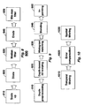
- our synthesis has the following steps: depth preprocessing 910, depth-based 3D warping 920, depth-based histogram matching 930, base plus assistant image blending 940, and depth-based in-painting 950, all described in greater detail below.
- the depth preprocessing is performed on the acquired scene depth data to correct errors and enhance the spatial and temporal consistencies of depths.
- the depth-based 3D warping corrects the discontinuity problem in the direct warping of textures caused by round-off errors.
- the depth-based warping uses camera parameters that describe a geometry of a scene.
- the depth-based histogram matching reduces illumination differences between two reference images.
- the base plus assistant image blending blends the two 3D warped reference images against the inaccuracy of the depth and camera parameters to produce the virtual image.
- the depth-based in-painting fills any remaining holes in the virtual image.
- Fig. 11 shows the steps for a first image 1101 and a second image 1102 to produce a synthesized virtual image 1103.
- the first and second images are to the left and right of the image for the desired virtual image.
- the depth data can be acquired using a depth or range camera, and computer graphics tools, or determined by a preferred depth estimation procedure.
- the depth preprocessing includes: temporal filtering 1010, initial error compensation 1020, and spatial filtering 1030.
- temporal filtering 1010 temporal filtering 1010
- initial error compensation 1020 initial error compensation 1020
- spatial filtering 1030 spatial filtering 1030.
- a median filtering instead of averaging filter because averaging filter results in new pixel depths which do not exist in the initial depth image, which degrades the quality of the rendering.
- a 1D median filter along the co-located pixels of consecutive depth image frames to reduce temporal inconsistency of depths belonging to the same object or background.
- the next step compensates for an initial error, which can be caused by an erroneous merge of foreground and background in the typical depth estimation process.
- the error occurs when the foreground and the background have similar textures, which are easy to distinguish visually, but difficult to remove.
- a ⁇ B x y max x y ⁇ B A B x y
- a ⁇ ⁇ ⁇ B x y min x y ⁇ B A B x y
- a B is structuring element which operates on the A.
- the A B is a masked region with B and ( x, y ) is a pixel in the image A .
- the final step filters outliers and removes noise in the estimated depth image using a 2D median filter.
- the depth image corresponding to the virtual image After the depth image corresponding to the virtual image is obtained, by inverse warping, we can use the depth image to locate the proper texture intensities from an adjacent images without generating false black-contours in the synthesized virtual image.
- To obtain the depth image corresponding to the virtual image we first warp the depth images of the corresponding reference images. In 3D warping, pixels in the reference image are back-projected to 3D spaces, and re-projected onto the target virtual image using camera parameters describing the geometry of the scene.
- the histograms of the pixel intensities of the two 3D warped reference images are adjusted to have a similar distribution. This process is applied for each component of the RGB data format in which the pixel intensities are expressed.
- the two 3D warped images are modified so that holes at identical corresponding locations, and then the median filter is applied to reduce noise.
- the two warped images similar textures except for slight differences in their illuminations. This modification greatly increases the accuracy of histogram matching as the existence of holes in the images has a huge impact on the shape of the histogram.
- the histogram h R [ v ] and cumulative histogram C R [ v ] of the right image are constructed in the same manner.
- the different lighting for each camera causes illumination and color differences, and differently affects each object and color component.
- the base image is the main reference image from which most of the pixel intensities are warped.
- the assistant image is used as a supplementary reference image for in-painting.
- the closer reference image to the virtual image is selected as the base image I B
- the other image is selected as the assistant image I A
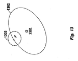
- Disocclusion regions are areas that cannot be seen in the reference image, but exist in the synthesized image. However, some holes still remain due to remaining disocclusion regions and wrong depths.
- a region ⁇ 1301 to be in-painted has a boundary ⁇ 1302.
- a pixel p belonging to the region ⁇ is in-painted using pixels in an adjacent region B ⁇ ( p ) 1303.
- our in-painting prefers the background pixels over the foreground pixels as follows p fg ⁇ ⁇ ⁇ fg ⁇ p bg ⁇ ⁇ ⁇ bg B ⁇ p fg ⁇ B ⁇ p bg where f g and b g represent the foreground and the background, respectively.
Claims (9)
- Procédé destiné à filtrer une image de profondeur, dans lequel ladite image de profondeur comprend un réseau de pixels à des emplacements (x, y), et dans lequel chaque pixel présente une valeur de profondeur quantifiée, le procédé comprenant les étapes consistant à :définir une fenêtre sur les pixels dans l'image de profondeur, dans lequel la taille de la fenêtre couvre un ensemble de pixels centrés au niveau de chaque pixel ;attribuer une valeur de profondeur représentative unique de l'ensemble de valeurs de pixels dans la fenêtre au pixel pour produire une image de profondeur traitée ;l'étape d'attribution comprenant les étapes consistant à :déterminer une valeur de profondeur médiane des pixels dans ladite fenêtre ;partitionner les valeurs de profondeur dans la fenêtre en un ensemble Slow et un ensemble Shigh selon la médiane, de telle sorte que l'ensemble Slow comprenne les valeurs de profondeur avec des profondeurs inférieures à la médiane et que l'ensemble Shigh comprenne les valeurs de profondeur avec des profondeurs supérieures à la médiane ;déterminer une profondeur Vlow et une profondeur Vhigh avec la fréquence d'occurrence la plus élevée dans les ensembles Slow et Shigh, respectivement ; etsélectionner parmi Vlow et Vhigh la valeur de profondeur qui est plus proche de la valeur de profondeur du pixel en tant que valeur de profondeur représentative unique, en filtrant chaque pixel dans l'image de profondeur traitée pour corriger les valeurs de profondeur aberrantes sans estomper les discontinuités de profondeur pour produire une image de profondeur filtrée.
- Procédé selon la revendication 1, dans lequel le filtrage est exécuté en appliquant un filtre médian pour éliminer les profondeurs aberrantes.
- Procédé selon la revendication 1, dans lequel la taille de la fenêtre est fixée à 3×3, 5×5 ou 7×7 pixels selon un paramètre de quantification utilisé pour coder l'image de profondeur.
- Procédé selon la revendication 1, dans lequel le filtrage est un filtre bilatéral.
- Procédé selon la revendication 1, dans lequel le filtrage est un filtre médian 3x3.
- Procédé selon la revendication 1, dans lequel le filtrage de l'image de profondeur est exécuté sur une image de profondeur reconstruite qui est une sortie d'un décodeur.
- Procédé selon la revendication 1, dans lequel le filtrage de l'image de profondeur est exécuté sur l'image de profondeur à l'intérieur d'une boucle de prédiction d'un décodeur pour produire une image de référence qui est utilisée pour prévoir une image de profondeur ultérieure à décoder.
- Procédé selon la revendication 1, dans lequel les images de profondeur sont sur-échantillonnées à partir d'une résolution réduite.
- Procédé selon la revendication 1, dans lequel les images de profondeur comprennent un bruit dû à un processus d'estimation.
Applications Claiming Priority (1)
| Application Number | Priority Date | Filing Date | Title |
|---|---|---|---|
| US12/405,864 US8270752B2 (en) | 2009-03-17 | 2009-03-17 | Depth reconstruction filter for depth coding videos |
Publications (2)
| Publication Number | Publication Date |
|---|---|
| EP2230640A1 EP2230640A1 (fr) | 2010-09-22 |
| EP2230640B1 true EP2230640B1 (fr) | 2013-07-10 |
Family
ID=42144831
Family Applications (1)
| Application Number | Title | Priority Date | Filing Date |
|---|---|---|---|
| EP10002458.7A Not-in-force EP2230640B1 (fr) | 2009-03-17 | 2010-03-09 | Verfahren zum Filtern von Tiefenbildern |
Country Status (3)
| Country | Link |
|---|---|
| US (1) | US8270752B2 (fr) |
| EP (1) | EP2230640B1 (fr) |
| JP (1) | JP5230669B2 (fr) |
Cited By (1)
| Publication number | Priority date | Publication date | Assignee | Title |
|---|---|---|---|---|
| CN104012086A (zh) * | 2011-12-19 | 2014-08-27 | 思科技术公司 | 用于视频会议环境中景深导向图像滤波的系统和方法 |
Families Citing this family (40)
| Publication number | Priority date | Publication date | Assignee | Title |
|---|---|---|---|---|
| US20120269458A1 (en) * | 2007-12-11 | 2012-10-25 | Graziosi Danillo B | Method for Generating High Resolution Depth Images from Low Resolution Depth Images Using Edge Layers |
| US8189943B2 (en) * | 2009-03-17 | 2012-05-29 | Mitsubishi Electric Research Laboratories, Inc. | Method for up-sampling depth images |
| KR20120003147A (ko) * | 2010-07-02 | 2012-01-10 | 삼성전자주식회사 | 루프 필터를 이용한 깊이 영상 부호화 장치 및 복호화 장치 |
| US8774267B2 (en) * | 2010-07-07 | 2014-07-08 | Spinella Ip Holdings, Inc. | System and method for transmission, processing, and rendering of stereoscopic and multi-view images |
| US8902283B2 (en) * | 2010-10-07 | 2014-12-02 | Sony Corporation | Method and apparatus for converting a two-dimensional image into a three-dimensional stereoscopic image |
| KR20120057216A (ko) * | 2010-11-26 | 2012-06-05 | 삼성전자주식회사 | 깊이 센서, 상기 깊이 센서의 노이즈 감소 방법, 및 상기 깊이 센서를 포함하는 신호 처리 시스템 |
| JP5858381B2 (ja) * | 2010-12-03 | 2016-02-10 | 国立大学法人名古屋大学 | 多視点画像合成方法及び多視点画像合成システム |
| US20120207386A1 (en) * | 2011-02-11 | 2012-08-16 | Microsoft Corporation | Updating A Low Frame Rate Image Using A High Frame Rate Image Stream |
| WO2012111757A1 (fr) * | 2011-02-18 | 2012-08-23 | ソニー株式会社 | Dispositif de traitement d'images et procédé de traitement d'images |
| US9338424B2 (en) | 2011-02-23 | 2016-05-10 | Koninklijlke Philips N.V. | Processing depth data of a three-dimensional scene |
| TWI462569B (zh) * | 2011-04-22 | 2014-11-21 | Mstar Semiconductor Inc | 三維影像攝相機及其相關控制方法 |
| US9681115B2 (en) * | 2011-07-25 | 2017-06-13 | Sony Corporation | In-painting method for 3D stereoscopic views generation using left and right images and a depth map |
| WO2013081383A1 (fr) * | 2011-11-29 | 2013-06-06 | 삼성전자주식회사 | Procédé et appareil pour convertir une image de profondeur dans une haute résolution |
| KR101978172B1 (ko) | 2011-11-29 | 2019-05-15 | 삼성전자주식회사 | 깊이 영상을 고해상도로 변환하는 방법 및 장치 |
| US20130202194A1 (en) * | 2012-02-05 | 2013-08-08 | Danillo Bracco Graziosi | Method for generating high resolution depth images from low resolution depth images using edge information |
| JP5362878B2 (ja) * | 2012-05-09 | 2013-12-11 | 株式会社日立国際電気 | 画像処理装置及び画像処理方法 |
| US9307252B2 (en) | 2012-06-04 | 2016-04-05 | City University Of Hong Kong | View synthesis distortion model for multiview depth video coding |
| US20150181204A1 (en) * | 2012-07-18 | 2015-06-25 | Sony Corporation | Image processing apparatus, image processing method, and image display device |
| WO2014013405A1 (fr) * | 2012-07-20 | 2014-01-23 | Koninklijke Philips N.V. | Métadonnées pour filtrage en profondeur |
| WO2014015460A1 (fr) * | 2012-07-23 | 2014-01-30 | Thomson Licensing | Représentation de vidéo tridimensionnelle (3d) utilisant une incorporation d'informations |
| LU92074B1 (en) * | 2012-09-18 | 2014-03-19 | Iee Sarl | Depth image enhancement method |
| KR101896301B1 (ko) | 2013-01-03 | 2018-09-07 | 삼성전자주식회사 | 깊이 영상 처리 장치 및 방법 |
| US9064295B2 (en) * | 2013-02-04 | 2015-06-23 | Sony Corporation | Enhanced video encoding using depth information |
| US10080036B2 (en) | 2013-05-16 | 2018-09-18 | City University Of Hong Kong | Method and apparatus for depth video coding using endurable view synthesis distortion |
| US9953400B2 (en) | 2013-07-23 | 2018-04-24 | Microsoft Technology Licensing, Llc | Adaptive path smoothing for video stabilization |
| WO2015010244A1 (fr) * | 2013-07-23 | 2015-01-29 | Microsoft Corporation | Lissage de chemin adaptatif pour stabiliser une vidéo |
| JP2015035658A (ja) * | 2013-08-07 | 2015-02-19 | キヤノン株式会社 | 画像処理装置、画像処理方法、および撮像装置 |
| US9076236B2 (en) | 2013-09-12 | 2015-07-07 | At&T Intellectual Property I, L.P. | Guided image upsampling using bitmap tracing |
| US20150077575A1 (en) * | 2013-09-13 | 2015-03-19 | Scott Krig | Virtual camera module for hybrid depth vision controls |
| US9736455B2 (en) | 2014-06-30 | 2017-08-15 | Nokia Technologies Oy | Method and apparatus for downscaling depth data for view plus depth data compression |
| CN104683783B (zh) * | 2015-01-08 | 2017-03-15 | 电子科技大学 | 一种自适应深度图滤波方法 |
| JP6818471B2 (ja) * | 2016-08-31 | 2021-01-20 | キヤノン株式会社 | 画像処理装置、画像処理方法、及びプログラム |
| US10694202B2 (en) * | 2016-12-01 | 2020-06-23 | Qualcomm Incorporated | Indication of bilateral filter usage in video coding |
| EP3351899B1 (fr) * | 2017-01-24 | 2020-06-17 | Leica Geosystems AG | Procédé et dispositif pour la colorisation de nuages de points tridimensionnels |
| EP3462415A1 (fr) * | 2017-09-29 | 2019-04-03 | Thomson Licensing | Procédé et dispositif de modification d'attributs de points d'une scène en 3d |
| EP3462408A1 (fr) | 2017-09-29 | 2019-04-03 | Thomson Licensing | Procédé de filtrage de pixels faux dans une carte de profondeur |
| CN108182666B (zh) * | 2017-12-27 | 2021-11-30 | 海信集团有限公司 | 一种视差校正方法、装置和终端 |
| JP2021018123A (ja) * | 2019-07-19 | 2021-02-15 | ソニーセミコンダクタソリューションズ株式会社 | 信号処理装置、信号処理方法 |
| CN110827209A (zh) * | 2019-09-26 | 2020-02-21 | 西安交通大学 | 一种联合颜色与深度信息的自适应深度图像修复方法 |
| US11430179B2 (en) | 2020-02-24 | 2022-08-30 | Microsoft Technology Licensing, Llc | Depth buffer dilation for remote rendering |
Family Cites Families (10)
| Publication number | Priority date | Publication date | Assignee | Title |
|---|---|---|---|---|
| US5848189A (en) * | 1996-03-25 | 1998-12-08 | Focus Automation Systems Inc. | Method, apparatus and system for verification of patterns |
| US5963675A (en) * | 1996-04-17 | 1999-10-05 | Sarnoff Corporation | Pipelined pyramid processor for image processing systems |
| DE69824230T2 (de) * | 1997-04-08 | 2005-07-07 | Koninklijke Philips Electronics N.V. | Verarbeitungssystem einer verrauschten Bildsequenz und medizinisches Untersuchungsgerät mit einem solchen System |
| US7133569B1 (en) * | 2000-07-31 | 2006-11-07 | Polaroid Corporation | Aliasing artifact attenuation system |
| US6816627B2 (en) * | 2001-04-12 | 2004-11-09 | Lockheed Martin Corporation | System for morphological image fusion and change detection |
| US6973218B2 (en) * | 2001-04-25 | 2005-12-06 | Lockheed Martin Corporation | Dynamic range compression |
| US7085401B2 (en) * | 2001-10-31 | 2006-08-01 | Infowrap Systems Ltd. | Automatic object extraction |
| US6847728B2 (en) * | 2002-12-09 | 2005-01-25 | Sarnoff Corporation | Dynamic depth recovery from multiple synchronized video streams |
| US20110097010A1 (en) * | 2006-12-13 | 2011-04-28 | Jian Wang | Method and system for reducing noise in images in video coding |
| US7889949B2 (en) * | 2007-04-30 | 2011-02-15 | Microsoft Corporation | Joint bilateral upsampling |
-
2009
- 2009-03-17 US US12/405,864 patent/US8270752B2/en not_active Expired - Fee Related
-
2010
- 2010-02-19 JP JP2010034830A patent/JP5230669B2/ja not_active Expired - Fee Related
- 2010-03-09 EP EP10002458.7A patent/EP2230640B1/fr not_active Not-in-force
Cited By (2)
| Publication number | Priority date | Publication date | Assignee | Title |
|---|---|---|---|---|
| CN104012086A (zh) * | 2011-12-19 | 2014-08-27 | 思科技术公司 | 用于视频会议环境中景深导向图像滤波的系统和方法 |
| CN104012086B (zh) * | 2011-12-19 | 2017-05-31 | 思科技术公司 | 用于视频会议环境中景深导向图像滤波的系统和方法 |
Also Published As
| Publication number | Publication date |
|---|---|
| US20100239180A1 (en) | 2010-09-23 |
| JP5230669B2 (ja) | 2013-07-10 |
| US8270752B2 (en) | 2012-09-18 |
| JP2010218549A (ja) | 2010-09-30 |
| EP2230640A1 (fr) | 2010-09-22 |
Similar Documents
| Publication | Publication Date | Title |
|---|---|---|
| EP2230640B1 (fr) | Verfahren zum Filtern von Tiefenbildern | |
| EP2230855B1 (fr) | Synthèse d'images virtuelles à partir d'images de texture et de profondeur | |
| EP2230856B1 (fr) | Procédé d'échantillonnage d'images | |
| US8213500B2 (en) | Methods and systems for processing film grain noise | |
| US20160048952A1 (en) | Algorithm and device for image processing | |
| US20120269458A1 (en) | Method for Generating High Resolution Depth Images from Low Resolution Depth Images Using Edge Layers | |
| US20080292201A1 (en) | Pre-processing method and system for data reduction of video sequences and bit rate reduction of compressed video sequences using spatial filtering | |
| US20100027686A1 (en) | Image compression and decompression | |
| US20200304797A1 (en) | Cluster refinement for texture synthesis in video coding | |
| US11323717B2 (en) | Frequency adjustment for texture synthesis in video coding | |
| US8965141B2 (en) | Image filtering based on structural information | |
| US20130202194A1 (en) | Method for generating high resolution depth images from low resolution depth images using edge information | |
| US20160241884A1 (en) | Selective perceptual masking via scale separation in the spatial and temporal domains for use in data compression with motion compensation | |
| US11252413B2 (en) | Polynomial fitting for motion compensation and luminance reconstruction in texture synthesis | |
| Sandić-Stanković et al. | Fast blind quality assessment of DIBR-synthesized video based on high-high wavelet subband | |
| US8897378B2 (en) | Selective perceptual masking via scale separation in the spatial and temporal domains using intrinsic images for use in data compression | |
| Min et al. | Weighted mode filtering and its applications to depth video enhancement and coding | |
| WO2014163893A1 (fr) | Masquage perceptif sélectif par l'intermédiaire d'une séparation d'échelle dans les domaines spatial et temporel à l'aide d'images intrinsèques, destiné à être utilisé dans une compression de données | |
| Oh | Texture processing for image/video coding and super-resolution applications |
Legal Events
| Date | Code | Title | Description |
|---|---|---|---|
| PUAI | Public reference made under article 153(3) epc to a published international application that has entered the european phase |
Free format text: ORIGINAL CODE: 0009012 |
|
| AK | Designated contracting states |
Kind code of ref document: A1 Designated state(s): AT BE BG CH CY CZ DE DK EE ES FI FR GB GR HR HU IE IS IT LI LT LU LV MC MK MT NL NO PL PT RO SE SI SK SM TR |
|
| AX | Request for extension of the european patent |
Extension state: AL BA ME RS |
|
| RIN1 | Information on inventor provided before grant (corrected) |
Inventor name: OH, KWAN-JUNG Inventor name: VETRO, ANTHONY Inventor name: YEA, SEHOON |
|
| 17P | Request for examination filed |
Effective date: 20110322 |
|
| GRAP | Despatch of communication of intention to grant a patent |
Free format text: ORIGINAL CODE: EPIDOSNIGR1 |
|
| GRAS | Grant fee paid |
Free format text: ORIGINAL CODE: EPIDOSNIGR3 |
|
| GRAA | (expected) grant |
Free format text: ORIGINAL CODE: 0009210 |
|
| AK | Designated contracting states |
Kind code of ref document: B1 Designated state(s): AT BE BG CH CY CZ DE DK EE ES FI FR GB GR HR HU IE IS IT LI LT LU LV MC MK MT NL NO PL PT RO SE SI SK SM TR |
|
| REG | Reference to a national code |
Ref country code: GB Ref legal event code: FG4D |
|
| REG | Reference to a national code |
Ref country code: CH Ref legal event code: EP Ref country code: AT Ref legal event code: REF Ref document number: 621346 Country of ref document: AT Kind code of ref document: T Effective date: 20130715 |
|
| REG | Reference to a national code |
Ref country code: IE Ref legal event code: FG4D |
|
| REG | Reference to a national code |
Ref country code: DE Ref legal event code: R096 Ref document number: 602010008317 Country of ref document: DE Effective date: 20130905 |
|
| PG25 | Lapsed in a contracting state [announced via postgrant information from national office to epo] |
Ref country code: SI Free format text: LAPSE BECAUSE OF FAILURE TO SUBMIT A TRANSLATION OF THE DESCRIPTION OR TO PAY THE FEE WITHIN THE PRESCRIBED TIME-LIMIT Effective date: 20130710 |
|
| REG | Reference to a national code |
Ref country code: AT Ref legal event code: MK05 Ref document number: 621346 Country of ref document: AT Kind code of ref document: T Effective date: 20130710 |
|
| REG | Reference to a national code |
Ref country code: NL Ref legal event code: VDEP Effective date: 20130710 |
|
| REG | Reference to a national code |
Ref country code: LT Ref legal event code: MG4D |
|
| PG25 | Lapsed in a contracting state [announced via postgrant information from national office to epo] |
Ref country code: AT Free format text: LAPSE BECAUSE OF FAILURE TO SUBMIT A TRANSLATION OF THE DESCRIPTION OR TO PAY THE FEE WITHIN THE PRESCRIBED TIME-LIMIT Effective date: 20130710 Ref country code: HR Free format text: LAPSE BECAUSE OF FAILURE TO SUBMIT A TRANSLATION OF THE DESCRIPTION OR TO PAY THE FEE WITHIN THE PRESCRIBED TIME-LIMIT Effective date: 20130710 Ref country code: SE Free format text: LAPSE BECAUSE OF FAILURE TO SUBMIT A TRANSLATION OF THE DESCRIPTION OR TO PAY THE FEE WITHIN THE PRESCRIBED TIME-LIMIT Effective date: 20130710 Ref country code: LT Free format text: LAPSE BECAUSE OF FAILURE TO SUBMIT A TRANSLATION OF THE DESCRIPTION OR TO PAY THE FEE WITHIN THE PRESCRIBED TIME-LIMIT Effective date: 20130710 Ref country code: PT Free format text: LAPSE BECAUSE OF FAILURE TO SUBMIT A TRANSLATION OF THE DESCRIPTION OR TO PAY THE FEE WITHIN THE PRESCRIBED TIME-LIMIT Effective date: 20131111 Ref country code: BE Free format text: LAPSE BECAUSE OF FAILURE TO SUBMIT A TRANSLATION OF THE DESCRIPTION OR TO PAY THE FEE WITHIN THE PRESCRIBED TIME-LIMIT Effective date: 20130710 Ref country code: NO Free format text: LAPSE BECAUSE OF FAILURE TO SUBMIT A TRANSLATION OF THE DESCRIPTION OR TO PAY THE FEE WITHIN THE PRESCRIBED TIME-LIMIT Effective date: 20131010 Ref country code: CY Free format text: LAPSE BECAUSE OF FAILURE TO SUBMIT A TRANSLATION OF THE DESCRIPTION OR TO PAY THE FEE WITHIN THE PRESCRIBED TIME-LIMIT Effective date: 20130904 Ref country code: IS Free format text: LAPSE BECAUSE OF FAILURE TO SUBMIT A TRANSLATION OF THE DESCRIPTION OR TO PAY THE FEE WITHIN THE PRESCRIBED TIME-LIMIT Effective date: 20131110 |
|
| PG25 | Lapsed in a contracting state [announced via postgrant information from national office to epo] |
Ref country code: LV Free format text: LAPSE BECAUSE OF FAILURE TO SUBMIT A TRANSLATION OF THE DESCRIPTION OR TO PAY THE FEE WITHIN THE PRESCRIBED TIME-LIMIT Effective date: 20130710 Ref country code: PL Free format text: LAPSE BECAUSE OF FAILURE TO SUBMIT A TRANSLATION OF THE DESCRIPTION OR TO PAY THE FEE WITHIN THE PRESCRIBED TIME-LIMIT Effective date: 20130710 Ref country code: GR Free format text: LAPSE BECAUSE OF FAILURE TO SUBMIT A TRANSLATION OF THE DESCRIPTION OR TO PAY THE FEE WITHIN THE PRESCRIBED TIME-LIMIT Effective date: 20131011 Ref country code: NL Free format text: LAPSE BECAUSE OF FAILURE TO SUBMIT A TRANSLATION OF THE DESCRIPTION OR TO PAY THE FEE WITHIN THE PRESCRIBED TIME-LIMIT Effective date: 20130710 Ref country code: ES Free format text: LAPSE BECAUSE OF FAILURE TO SUBMIT A TRANSLATION OF THE DESCRIPTION OR TO PAY THE FEE WITHIN THE PRESCRIBED TIME-LIMIT Effective date: 20131021 Ref country code: FI Free format text: LAPSE BECAUSE OF FAILURE TO SUBMIT A TRANSLATION OF THE DESCRIPTION OR TO PAY THE FEE WITHIN THE PRESCRIBED TIME-LIMIT Effective date: 20130710 |
|
| PG25 | Lapsed in a contracting state [announced via postgrant information from national office to epo] |
Ref country code: CY Free format text: LAPSE BECAUSE OF FAILURE TO SUBMIT A TRANSLATION OF THE DESCRIPTION OR TO PAY THE FEE WITHIN THE PRESCRIBED TIME-LIMIT Effective date: 20130710 |
|
| PG25 | Lapsed in a contracting state [announced via postgrant information from national office to epo] |
Ref country code: CZ Free format text: LAPSE BECAUSE OF FAILURE TO SUBMIT A TRANSLATION OF THE DESCRIPTION OR TO PAY THE FEE WITHIN THE PRESCRIBED TIME-LIMIT Effective date: 20130710 Ref country code: RO Free format text: LAPSE BECAUSE OF FAILURE TO SUBMIT A TRANSLATION OF THE DESCRIPTION OR TO PAY THE FEE WITHIN THE PRESCRIBED TIME-LIMIT Effective date: 20130710 Ref country code: DK Free format text: LAPSE BECAUSE OF FAILURE TO SUBMIT A TRANSLATION OF THE DESCRIPTION OR TO PAY THE FEE WITHIN THE PRESCRIBED TIME-LIMIT Effective date: 20130710 Ref country code: SK Free format text: LAPSE BECAUSE OF FAILURE TO SUBMIT A TRANSLATION OF THE DESCRIPTION OR TO PAY THE FEE WITHIN THE PRESCRIBED TIME-LIMIT Effective date: 20130710 Ref country code: EE Free format text: LAPSE BECAUSE OF FAILURE TO SUBMIT A TRANSLATION OF THE DESCRIPTION OR TO PAY THE FEE WITHIN THE PRESCRIBED TIME-LIMIT Effective date: 20130710 |
|
| PLBE | No opposition filed within time limit |
Free format text: ORIGINAL CODE: 0009261 |
|
| STAA | Information on the status of an ep patent application or granted ep patent |
Free format text: STATUS: NO OPPOSITION FILED WITHIN TIME LIMIT |
|
| PG25 | Lapsed in a contracting state [announced via postgrant information from national office to epo] |
Ref country code: IT Free format text: LAPSE BECAUSE OF FAILURE TO SUBMIT A TRANSLATION OF THE DESCRIPTION OR TO PAY THE FEE WITHIN THE PRESCRIBED TIME-LIMIT Effective date: 20130710 |
|
| 26N | No opposition filed |
Effective date: 20140411 |
|
| REG | Reference to a national code |
Ref country code: DE Ref legal event code: R097 Ref document number: 602010008317 Country of ref document: DE Effective date: 20140411 |
|
| PG25 | Lapsed in a contracting state [announced via postgrant information from national office to epo] |
Ref country code: LU Free format text: LAPSE BECAUSE OF FAILURE TO SUBMIT A TRANSLATION OF THE DESCRIPTION OR TO PAY THE FEE WITHIN THE PRESCRIBED TIME-LIMIT Effective date: 20140309 |
|
| REG | Reference to a national code |
Ref country code: CH Ref legal event code: PL |
|
| REG | Reference to a national code |
Ref country code: IE Ref legal event code: MM4A |
|
| PG25 | Lapsed in a contracting state [announced via postgrant information from national office to epo] |
Ref country code: CH Free format text: LAPSE BECAUSE OF NON-PAYMENT OF DUE FEES Effective date: 20140331 Ref country code: LI Free format text: LAPSE BECAUSE OF NON-PAYMENT OF DUE FEES Effective date: 20140331 Ref country code: IE Free format text: LAPSE BECAUSE OF NON-PAYMENT OF DUE FEES Effective date: 20140309 |
|
| REG | Reference to a national code |
Ref country code: FR Ref legal event code: PLFP Year of fee payment: 7 |
|
| PG25 | Lapsed in a contracting state [announced via postgrant information from national office to epo] |
Ref country code: MT Free format text: LAPSE BECAUSE OF FAILURE TO SUBMIT A TRANSLATION OF THE DESCRIPTION OR TO PAY THE FEE WITHIN THE PRESCRIBED TIME-LIMIT Effective date: 20130710 |
|
| PG25 | Lapsed in a contracting state [announced via postgrant information from national office to epo] |
Ref country code: SM Free format text: LAPSE BECAUSE OF FAILURE TO SUBMIT A TRANSLATION OF THE DESCRIPTION OR TO PAY THE FEE WITHIN THE PRESCRIBED TIME-LIMIT Effective date: 20130710 |
|
| PGFP | Annual fee paid to national office [announced via postgrant information from national office to epo] |
Ref country code: DE Payment date: 20160302 Year of fee payment: 7 |
|
| REG | Reference to a national code |
Ref country code: DE Ref legal event code: R084 Ref document number: 602010008317 Country of ref document: DE |
|
| PG25 | Lapsed in a contracting state [announced via postgrant information from national office to epo] |
Ref country code: MC Free format text: LAPSE BECAUSE OF FAILURE TO SUBMIT A TRANSLATION OF THE DESCRIPTION OR TO PAY THE FEE WITHIN THE PRESCRIBED TIME-LIMIT Effective date: 20130710 |
|
| PGFP | Annual fee paid to national office [announced via postgrant information from national office to epo] |
Ref country code: GB Payment date: 20160309 Year of fee payment: 7 Ref country code: FR Payment date: 20160208 Year of fee payment: 7 |
|
| REG | Reference to a national code |
Ref country code: GB Ref legal event code: 746 Effective date: 20160519 |
|
| PG25 | Lapsed in a contracting state [announced via postgrant information from national office to epo] |
Ref country code: BG Free format text: LAPSE BECAUSE OF FAILURE TO SUBMIT A TRANSLATION OF THE DESCRIPTION OR TO PAY THE FEE WITHIN THE PRESCRIBED TIME-LIMIT Effective date: 20130710 |
|
| PG25 | Lapsed in a contracting state [announced via postgrant information from national office to epo] |
Ref country code: TR Free format text: LAPSE BECAUSE OF FAILURE TO SUBMIT A TRANSLATION OF THE DESCRIPTION OR TO PAY THE FEE WITHIN THE PRESCRIBED TIME-LIMIT Effective date: 20130710 Ref country code: HU Free format text: LAPSE BECAUSE OF FAILURE TO SUBMIT A TRANSLATION OF THE DESCRIPTION OR TO PAY THE FEE WITHIN THE PRESCRIBED TIME-LIMIT; INVALID AB INITIO Effective date: 20100309 |
|
| REG | Reference to a national code |
Ref country code: DE Ref legal event code: R119 Ref document number: 602010008317 Country of ref document: DE |
|
| GBPC | Gb: european patent ceased through non-payment of renewal fee |
Effective date: 20170309 |
|
| REG | Reference to a national code |
Ref country code: FR Ref legal event code: ST Effective date: 20171130 |
|
| PG25 | Lapsed in a contracting state [announced via postgrant information from national office to epo] |
Ref country code: DE Free format text: LAPSE BECAUSE OF NON-PAYMENT OF DUE FEES Effective date: 20171003 Ref country code: FR Free format text: LAPSE BECAUSE OF NON-PAYMENT OF DUE FEES Effective date: 20170331 |
|
| PG25 | Lapsed in a contracting state [announced via postgrant information from national office to epo] |
Ref country code: GB Free format text: LAPSE BECAUSE OF NON-PAYMENT OF DUE FEES Effective date: 20170309 |
|
| PG25 | Lapsed in a contracting state [announced via postgrant information from national office to epo] |
Ref country code: MK Free format text: LAPSE BECAUSE OF FAILURE TO SUBMIT A TRANSLATION OF THE DESCRIPTION OR TO PAY THE FEE WITHIN THE PRESCRIBED TIME-LIMIT Effective date: 20130710 |