EP2230437B1 - Hinge device with a spherical joint - Google Patents
Hinge device with a spherical joint Download PDFInfo
- Publication number
- EP2230437B1 EP2230437B1 EP10002640.0A EP10002640A EP2230437B1 EP 2230437 B1 EP2230437 B1 EP 2230437B1 EP 10002640 A EP10002640 A EP 10002640A EP 2230437 B1 EP2230437 B1 EP 2230437B1
- Authority
- EP
- European Patent Office
- Prior art keywords
- bearing seat
- spherical joint
- hinge device
- positioning pins
- positioning
- Prior art date
- Legal status (The legal status is an assumption and is not a legal conclusion. Google has not performed a legal analysis and makes no representation as to the accuracy of the status listed.)
- Not-in-force
Links
Images




Classifications
-
- F—MECHANICAL ENGINEERING; LIGHTING; HEATING; WEAPONS; BLASTING
- F16—ENGINEERING ELEMENTS AND UNITS; GENERAL MEASURES FOR PRODUCING AND MAINTAINING EFFECTIVE FUNCTIONING OF MACHINES OR INSTALLATIONS; THERMAL INSULATION IN GENERAL
- F16C—SHAFTS; FLEXIBLE SHAFTS; ELEMENTS OR CRANKSHAFT MECHANISMS; ROTARY BODIES OTHER THAN GEARING ELEMENTS; BEARINGS
- F16C11/00—Pivots; Pivotal connections
- F16C11/04—Pivotal connections
- F16C11/10—Arrangements for locking
- F16C11/103—Arrangements for locking frictionally clamped
- F16C11/106—Arrangements for locking frictionally clamped for ball joints
-
- F—MECHANICAL ENGINEERING; LIGHTING; HEATING; WEAPONS; BLASTING
- F16—ENGINEERING ELEMENTS AND UNITS; GENERAL MEASURES FOR PRODUCING AND MAINTAINING EFFECTIVE FUNCTIONING OF MACHINES OR INSTALLATIONS; THERMAL INSULATION IN GENERAL
- F16C—SHAFTS; FLEXIBLE SHAFTS; ELEMENTS OR CRANKSHAFT MECHANISMS; ROTARY BODIES OTHER THAN GEARING ELEMENTS; BEARINGS
- F16C11/00—Pivots; Pivotal connections
- F16C11/04—Pivotal connections
- F16C11/06—Ball-joints; Other joints having more than one degree of angular freedom, i.e. universal joints
- F16C11/0604—Construction of the male part
-
- F—MECHANICAL ENGINEERING; LIGHTING; HEATING; WEAPONS; BLASTING
- F16—ENGINEERING ELEMENTS AND UNITS; GENERAL MEASURES FOR PRODUCING AND MAINTAINING EFFECTIVE FUNCTIONING OF MACHINES OR INSTALLATIONS; THERMAL INSULATION IN GENERAL
- F16M—FRAMES, CASINGS OR BEDS OF ENGINES, MACHINES OR APPARATUS, NOT SPECIFIC TO ENGINES, MACHINES OR APPARATUS PROVIDED FOR ELSEWHERE; STANDS; SUPPORTS
- F16M11/00—Stands or trestles as supports for apparatus or articles placed thereon ; Stands for scientific apparatus such as gravitational force meters
- F16M11/02—Heads
- F16M11/04—Means for attachment of apparatus; Means allowing adjustment of the apparatus relatively to the stand
- F16M11/06—Means for attachment of apparatus; Means allowing adjustment of the apparatus relatively to the stand allowing pivoting
- F16M11/12—Means for attachment of apparatus; Means allowing adjustment of the apparatus relatively to the stand allowing pivoting in more than one direction
- F16M11/14—Means for attachment of apparatus; Means allowing adjustment of the apparatus relatively to the stand allowing pivoting in more than one direction with ball-joint
-
- F—MECHANICAL ENGINEERING; LIGHTING; HEATING; WEAPONS; BLASTING
- F16—ENGINEERING ELEMENTS AND UNITS; GENERAL MEASURES FOR PRODUCING AND MAINTAINING EFFECTIVE FUNCTIONING OF MACHINES OR INSTALLATIONS; THERMAL INSULATION IN GENERAL
- F16M—FRAMES, CASINGS OR BEDS OF ENGINES, MACHINES OR APPARATUS, NOT SPECIFIC TO ENGINES, MACHINES OR APPARATUS PROVIDED FOR ELSEWHERE; STANDS; SUPPORTS
- F16M13/00—Other supports for positioning apparatus or articles; Means for steadying hand-held apparatus or articles
-
- F—MECHANICAL ENGINEERING; LIGHTING; HEATING; WEAPONS; BLASTING
- F16—ENGINEERING ELEMENTS AND UNITS; GENERAL MEASURES FOR PRODUCING AND MAINTAINING EFFECTIVE FUNCTIONING OF MACHINES OR INSTALLATIONS; THERMAL INSULATION IN GENERAL
- F16M—FRAMES, CASINGS OR BEDS OF ENGINES, MACHINES OR APPARATUS, NOT SPECIFIC TO ENGINES, MACHINES OR APPARATUS PROVIDED FOR ELSEWHERE; STANDS; SUPPORTS
- F16M13/00—Other supports for positioning apparatus or articles; Means for steadying hand-held apparatus or articles
- F16M13/02—Other supports for positioning apparatus or articles; Means for steadying hand-held apparatus or articles for supporting on, or attaching to, an object, e.g. tree, gate, window-frame, cycle
-
- F—MECHANICAL ENGINEERING; LIGHTING; HEATING; WEAPONS; BLASTING
- F16—ENGINEERING ELEMENTS AND UNITS; GENERAL MEASURES FOR PRODUCING AND MAINTAINING EFFECTIVE FUNCTIONING OF MACHINES OR INSTALLATIONS; THERMAL INSULATION IN GENERAL
- F16M—FRAMES, CASINGS OR BEDS OF ENGINES, MACHINES OR APPARATUS, NOT SPECIFIC TO ENGINES, MACHINES OR APPARATUS PROVIDED FOR ELSEWHERE; STANDS; SUPPORTS
- F16M2200/00—Details of stands or supports
- F16M2200/02—Locking means
- F16M2200/021—Locking means for rotational movement
- F16M2200/024—Locking means for rotational movement by positive interaction, e.g. male-female connections
-
- F—MECHANICAL ENGINEERING; LIGHTING; HEATING; WEAPONS; BLASTING
- F16—ENGINEERING ELEMENTS AND UNITS; GENERAL MEASURES FOR PRODUCING AND MAINTAINING EFFECTIVE FUNCTIONING OF MACHINES OR INSTALLATIONS; THERMAL INSULATION IN GENERAL
- F16M—FRAMES, CASINGS OR BEDS OF ENGINES, MACHINES OR APPARATUS, NOT SPECIFIC TO ENGINES, MACHINES OR APPARATUS PROVIDED FOR ELSEWHERE; STANDS; SUPPORTS
- F16M2200/00—Details of stands or supports
- F16M2200/04—Balancing means
- F16M2200/041—Balancing means for balancing rotational movement of the head
Definitions
- This invention relates to a hinge device and, more particularly, to a hinge device having a spherical joint.
- the electronic devices can further be connected with hinge devices according to needs in use.
- the hinge device in a car can be used for mounting an object such as a GPS device or a PDA to facilitate watch and operation by users.
- the object such as a digital camera, a tablet PC and so on, can also be mounted to the hinge device to facilitate operation.
- the object mounted to the hinge device can be rotated relative to the hinge device, such that the users can adjust the device to an angle at which the object is convenient for operation or watch.
- the object mounted to the hinge device can be rotated relative to the hinge device via a uniaxial rotatable bracket.
- a rotatable range of the device can be improved via the combination of more than two uniaxial rotatable brackets, compared with that of a rotatable structure in a spherical joint type, the rotatable range of the device is still limited.
- the users need to adjust an angle of the rotatable structure in the spherical joint type, first they need to release a clamp of the rotatable structure, and then they can lock the clamp after adjusting to a suitable angle.
- the above operation needs to be repeated, which is still inconvenient in use.
- WO 00/41493 A2 discloses a locking joint mechanism according to the preamble portion of claim 1.
- a similar device is also pre-known from CH 83 831 A .
- US 1 780 383 A refers to a camera tripod comprising a spherical joint including positioning pins.
- This invention provides a hinge device having a wide rotatable range and simple operation as defined in claim 1.
- the invention provides a hinge device including a bearing seat, a spherical joint, a plurality of positioning pins, and a retaining ring.
- the bearing seat has a containing recess.
- the spherical joint is rotatably disposed in the containing recess, and the surface of the spherical joint has a plurality of positioning holes.
- the positioning pins are disposed at the bearing seat.
- the positioning pins are capable of sliding toward or away from the spherical joint, and correspond to parts of the positioning holes respectively when the spherical joint rotates to a specific position relative to the bearing seat.
- the retaining ring is disposed at an opening of the containing recess of the bearing seat and surrounds the positioning pins. The retaining ring is against the positioning pins to allow the positioning pins to slide toward the spherical joint thus to be fastened in the corresponding positioning holes when the spherical joint rotates to the specific position relative to the bearing seat.
- the retaining ring has a plurality of protrusions at the inner side thereof, and that the retaining ring comes into a mechanical contract with the positioning pins by means of the protrusions by rotating said retaining ring by a specific angle relative to the bearing seat.
- the bearing seat may include a cup-shaped body and a cover.
- the cup-shaped body provides the containing recess.
- the cup-shaped body has a plurality of notches at the periphery of the opening of the containing recess for containing the positioning pins, to allow portions of the positioning pins to protrude from an inner wall of the containing recess.
- the cover is disposed at the opening of the containing recess to retain the spherical joint in the containing recess, and a hole is disposed at the center of the cover for exposing a portion of the spherical joint.
- the hinge device may further include a plurality of elastic elements disposed between the positioning pins and the bearing seat.
- each of the elastic elements may be a spring.
- the retaining ring has a plurality of protrusions at the inner side thereof, and the retaining ring comes into a mechanical contact with the positioning pins by means of the protrusions by rotating said retaining ring by a specific angle relative to the bearing seat.
- the retaining ring may include an outer ring and an inner ring.
- the outer ring surrounds the positioning pins.
- the inner ring is disposed between the outer ring and the positioning pins for providing the protrusions.
- the inner ring may be a ring-shaped elastic sheet, and a portion of the ring-shaped elastic sheet may be bent inwardly to form the protrusions.
- the retaining ring and the bearing seat may have at least one first positioning structure and at least one second positioning structure corresponding to each other, respectively. After the retaining ring is rotated the specific angle relative to the bearing seat, the first positioning structure and the second positioning structure may be engaged with each other.
- the first positioning structure may include a first protruding rib.
- the second positioning structure may include two blocking portions and a second protruding rib.
- the first protruding rib is disposed to move between the two blocking portions.
- the second protruding rib is adjacent to one of the blocking portions. Therefore, after the retaining ring rotates the specific angle relative to the bearing seat, the first protruding rib is engaged between the second protruding rib and the adjacent blocking portion.
- the hinge device may further include a fixed bracket connected with the bearing seat or the spherical joint.
- the hinge device in the invention has a wide rotatable range via the rotation of the spherical joint relative to the bearing seat.
- the positioning pins can be pushed into the positioning holes of the spherical joint by the rotation of the retaining ring thus to achieve a positioning function. Therefore, users can conveniently operate the hinge device.
- FIG. 1 is a side view showing a hinge device according to one embodiment of the invention.
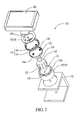
- FIG. 2 is an exploded diagram showing the hinge device in FIG. 1 .
- FIG. 3 to FIG. 5 are three-dimensional diagrams showing parts of the hinge device in FIG. 1 . Please refer to FIG. 1 to FIG. 5 .
- a hinge device 100 in the embodiment includes a bearing seat 110, a spherical joint 120, a plurality of positioning pins 130 (four positioning pins 130 are shown), and a retaining ring 140.
- the bearing seat 110 has a containing recess 112.
- the spherical joint 120 is disposed in the containing recess 112, and the surface of the spherical joint 120 has a plurality of positioning holes 122.
- the positioning pins 130 are disposed at the bearing seat 110, and portions of the positioning pins 130 protrude from an inner wall of the containing recess 112.
- the positioning pins 130 are disposed to slide toward or away from the spherical joint 120. After the spherical joint 120 rotates to a specific position relative to the bearing seat 110, the positioning pins 130 are inserted into the corresponding positioning holes 122, respectively.
- the retaining ring 140 is disposed at the bearing seat 110. After the spherical joint 120 rotates to the specific position relative to the bearing seat 110, the retaining ring 140 is against the positioning pins 130 to allow the positioning pins 130 to be fastened in the corresponding positioning holes 122.
- the four positioning pins 130 can correspond to the four positioning holes 122.
- a user can rotate the retaining ring 140 to push the four positioning pins 130 into the corresponding four positioning holes 122, respectively, such that the spherical joint 120 and the bearing seat 110 are fixed at a relative angle.
- the user can finish the operation of the hinge device 100 via simple steps of rotating the spherical joint 120 and rotating the retaining ring 140.
- the bearing seat 110 includes a cup-shaped body 114 and a cover 116.
- the cup-shaped body 114 provides the containing recess 112, and the cup-shaped body 114 has a plurality of notches 118 at the periphery of an opening of the containing recess 112 for containing the positioning pins 130.
- the periphery of the opening of the containing recess 112 has a protruding edge 112a, and the notches 118 are formed at the protruding edge 112a.
- the cover 116 is disposed at the opening of the containing recess 112 to retain the spherical joint 120 in the containing recess 112.
- a hole 116a is disposed at the center of the cover 116 for exposing a portion of the spherical joint 120.
- the positioning pins 130 slide toward or away from the spherical joint 120 by sliding relative to the notches 118.
- the retaining ring 140 is disposed at the opening of the containing recess 112 and surrounds the positioning pins 130.
- the retaining ring 140 has a plurality of protrusions 144a at the inner side. After the retaining ring 140 is rotated a specific angle relative to the bearing seat 110, the retaining ring 140 can be against the positioning pins 130 by the protrusions 144a.
- the retaining ring 140 includes an outer ring 142 and an inner ring 144.
- the outer ring 142 surrounds the positioning pins 130.
- the inner ring 144 is disposed between the outer ring 142 and the positioning pins 130 for providing the protrusions 144a.
- the inner ring 144 is a ring-shaped elastic sheet, and a portion of the ring-shaped elastic sheet is bent inwardly to form the protrusions 144a.
- FIG. 6A and FIG. 6B are top views showing parts of the hinge device in FIG. 1 in operation.
- FIG. 7A and FIG. 7B are three-dimensional diagrams showing parts of the hinge device in FIG. 1 in operation. Please refer to FIG. 6A and FIG. 7A .
- the user can rotate the spherical joint 120 to the specific position relative to the bearing seat 110, such that the positioning pins 130 correspond to the positioning holes 122.
- the positioning pins 130 are not wholly pushed into the corresponding positioning holes 122. That is, the positioning pins 130 and the spherical joint 120 just have slight structural interference.
- the spherical joint 120 can still be rotated relative to the bearing seat 110, and when rotating the spherical joint 120, the user can feel whether the positioning pins 130 correspond to the positioning holes 122 via the slight structural interference thus to achieve a preliminary positioning function.
- the retaining ring 140 can be rotated to allow the protrusions 144a to be rotated to correspond to the positioning pins 130, such that the positioning pins 130 are pushed into the positioning holes 122 via the protrusions 144a.
- the spherical joint 120 and the bearing seat 110 are fixed at the relative angle via the structural interference between the positioning pins 130 and the spherical joint 120.
- the hinge device 100 further includes a plurality of elastic elements 150.
- Each of the elastic elements 150 may be a spring and is disposed between the positioning pins 130 and the bearing seat 110.
- each of the springs is sleeved on the respective positioning pin 130.
- FIG. 8A and FIG. 8B are three-dimensional diagrams showing parts of the hinge device in FIG. 1 in operation. Please refer to FIG. 6A , FIG. 6B , FIG. 8A, and FIG. 8B .
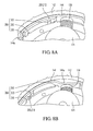
- the retaining ring 140 and the bearing seat 110 have at least one first positioning structure 200 and at least one second positioning structure 300 corresponding to each other, respectively. After the retaining ring 140 is rotated the specific angle relative to the bearing seat 110, the first positioning structure 200 and the second positioning structure 300 are engaged with each other (as shown in FIG. 6B and FIG. 8B ). There may be a plurality of positioning structures. In the embodiment, the numbers of the first positioning structure 200 and the second positioning structure 300 are four, respectively.
- the first positioning structure 200 includes a first protruding rib 210.
- the second positioning structure 300 includes two blocking portions 310 and a second protruding rib 320.
- the first protruding rib 210 is disposed to move between the two blocking portions 310.
- the second protruding rib 320 is adjacent to one of the blocking portions 310. Therefore, after the retaining ring 140 is rotated the specific angle relative to the bearing seat 110 to allow the positioning pins 130 to be fastened in the corresponding positioning holes 122 (as shown in FIG. 6B and FIG.
- the first protruding rib 210 is engaged between the second protruding rib 320 and the adjacent blocking portion 310 thereof, such that the protrusions 144a can be firmly fixed to correspond to the positioning pins 130.
- the first positioning structure 200 and the second positioning structure 300 may also be disposed at the bearing seat 110 and the retaining ring 140, respectively, and they may have the same positioning function as mentioned above.
- the hinge device 100 further includes a fixed bracket 160.
- the fixed bracket 160 is connected with the bearing seat 110, and the spherical joint 120 is adapted to be connected with an object 400.
- the object 400 may be a personal digital assistant (PDA), a tablet PC, a digital camera, a global positioning system (GPS), or other electronic devices.
- PDA personal digital assistant
- the fixed bracket 160 may further be connected with the spherical joint 120, and the bearing seat 110 may be connected with the object 400.
- the spherical joint 120 has a connecting portion 124.
- the hole 116a exposes the portion of the spherical joint 120, and the connecting portion 124 extends from the portion of the spherical joint 120 exposed from the hole 116a to be connected with the object 400.
- FIG. 9 is a schematic diagram showing a rotatable range of the hinge device in FIG. 1 .
- the rotatable range of the object 400 relative to the hinge device 100 can cover a spherical surface S.
- the user When the user is to adjust the angle of the object 400, the user only needs to rotate the retaining ring 140 to release the spherical joint 120 and the bearing seat 110 which are relatively fixed. After the user rotates the object 400 to a suitable angle, he or she can rotate the retaining ring 140 again to fix the spherical joint 120 and the bearing seat 110 at the relative angle.
- the hinge device in the invention has a wide rotatable range via the rotation of the spherical joint relative to the bearing seat, and the positioning pins can be pushed into the positioning holes of the spherical joint via the rotation of the retaining ring thus to achieve a positioning function. Therefore, users can conveniently operate the hinge device.
- the first protruding rib of the retaining ring can be engaged between the second protruding rib and the blocking portion of the bearing seat, such that the protrusions of the retaining ring can be fixed to correspond to the positioning pins thus to allow the object and the hinge device to be capable of being firmly fixed at a specific relative angle.
Landscapes
- Engineering & Computer Science (AREA)
- General Engineering & Computer Science (AREA)
- Mechanical Engineering (AREA)
- Pivots And Pivotal Connections (AREA)
Description
- This Non-provisional application claims priority under 35 U.S.C. §119(a) on Patent Application No(s).
098109188 - This invention relates to a hinge device and, more particularly, to a hinge device having a spherical joint.
- With continuous improvement of information technology, various kinds of electronic devices, such as personal digital assistants (PDAs), tablet PCs, digital cameras, global positioning system (GPS) devices and so on, come out one after another. The electronic devices can further be connected with hinge devices according to needs in use. For example, the hinge device in a car can be used for mounting an object such as a GPS device or a PDA to facilitate watch and operation by users. Furthermore, the object, such as a digital camera, a tablet PC and so on, can also be mounted to the hinge device to facilitate operation.
- Generally speaking, the object mounted to the hinge device can be rotated relative to the hinge device, such that the users can adjust the device to an angle at which the object is convenient for operation or watch. The object mounted to the hinge device can be rotated relative to the hinge device via a uniaxial rotatable bracket.
- However, although a rotatable range of the device can be improved via the combination of more than two uniaxial rotatable brackets, compared with that of a rotatable structure in a spherical joint type, the rotatable range of the device is still limited. However, in using the rotatable structure in the spherical joint type, when the users need to adjust an angle of the rotatable structure in the spherical joint type, first they need to release a clamp of the rotatable structure, and then they can lock the clamp after adjusting to a suitable angle. Thus, each time the adjustment is performed, the above operation needs to be repeated, which is still inconvenient in use.
-
WO 00/41493 A2CH 83 831 A -
US 1 780 383 A refers to a camera tripod comprising a spherical joint including positioning pins. - This invention provides a hinge device having a wide rotatable range and simple operation as defined in claim 1.
- The invention provides a hinge device including a bearing seat, a spherical joint, a plurality of positioning pins, and a retaining ring. The bearing seat has a containing recess. The spherical joint is rotatably disposed in the containing recess, and the surface of the spherical joint has a plurality of positioning holes. The positioning pins are disposed at the bearing seat. The positioning pins are capable of sliding toward or away from the spherical joint, and correspond to parts of the positioning holes respectively when the spherical joint rotates to a specific position relative to the bearing seat. The retaining ring is disposed at an opening of the containing recess of the bearing seat and surrounds the positioning pins. The retaining ring is against the positioning pins to allow the positioning pins to slide toward the spherical joint thus to be fastened in the corresponding positioning holes when the spherical joint rotates to the specific position relative to the bearing seat.
- The retaining ring has a plurality of protrusions at the inner side thereof, and that the retaining ring comes into a mechanical contract with the positioning pins by means of the protrusions by rotating said retaining ring by a specific angle relative to the bearing seat.
- In one embodiment of the invention, the bearing seat may include a cup-shaped body and a cover. The cup-shaped body provides the containing recess. The cup-shaped body has a plurality of notches at the periphery of the opening of the containing recess for containing the positioning pins, to allow portions of the positioning pins to protrude from an inner wall of the containing recess. The cover is disposed at the opening of the containing recess to retain the spherical joint in the containing recess, and a hole is disposed at the center of the cover for exposing a portion of the spherical joint.
- In one embodiment of the invention, the hinge device may further include a plurality of elastic elements disposed between the positioning pins and the bearing seat.
- In one embodiment of the invention, each of the elastic elements may be a spring.
- Accoring to the present invention, the retaining ring has a plurality of protrusions at the inner side thereof, and the retaining ring comes into a mechanical contact with the positioning pins by means of the protrusions by rotating said retaining ring by a specific angle relative to the bearing seat.
- In one embodiment of the invention, the retaining ring may include an outer ring and an inner ring. The outer ring surrounds the positioning pins. The inner ring is disposed between the outer ring and the positioning pins for providing the protrusions.
- In one embodiment of the invention, the inner ring may be a ring-shaped elastic sheet, and a portion of the ring-shaped elastic sheet may be bent inwardly to form the protrusions.
- In one embodiment of the invention, the retaining ring and the bearing seat may have at least one first positioning structure and at least one second positioning structure corresponding to each other, respectively. After the retaining ring is rotated the specific angle relative to the bearing seat, the first positioning structure and the second positioning structure may be engaged with each other.
- In one embodiment of the invention, the first positioning structure may include a first protruding rib. The second positioning structure may include two blocking portions and a second protruding rib. The first protruding rib is disposed to move between the two blocking portions. The second protruding rib is adjacent to one of the blocking portions. Therefore, after the retaining ring rotates the specific angle relative to the bearing seat, the first protruding rib is engaged between the second protruding rib and the adjacent blocking portion.
- In one embodiment of the invention, the hinge device may further include a fixed bracket connected with the bearing seat or the spherical joint.
- To sum up, the hinge device in the invention has a wide rotatable range via the rotation of the spherical joint relative to the bearing seat. In addition, the positioning pins can be pushed into the positioning holes of the spherical joint by the rotation of the retaining ring thus to achieve a positioning function. Therefore, users can conveniently operate the hinge device.
- These and other features, aspects, and advantages of the present invention will become better understood with regard to the following description, appended claims, and accompanying drawings.
-
-
FIG. 1 is a side view showing a hinge device according to one embodiment of the invention; -
FIG. 2 is an exploded diagram showing the hinge device inFIG. 1 ; -
FIG. 3 to FIG. 5 are three-dimensional diagrams showing parts of the hinge device inFIG. 1 ; -
FIG. 6A andFIG. 6B are top views showing parts of the hinge device inFIG. 1 in operation; -
FIG. 7A and FIG. 7B are three-dimensional diagrams showing parts of the hinge device inFIG. 1 in operation; -
FIG. 8A and FIG. 8B are three-dimensional diagrams showing parts of the hinge device inFIG. 1 in operation; and -
FIG. 9 is a schematic diagram showing a rotatable range of the hinge device inFIG. 1 . -
FIG. 1 is a side view showing a hinge device according to one embodiment of the invention.FIG. 2 is an exploded diagram showing the hinge device inFIG. 1 .FIG. 3 to FIG. 5 are three-dimensional diagrams showing parts of the hinge device inFIG. 1 . Please refer toFIG. 1 to FIG. 5 . Ahinge device 100 in the embodiment includes abearing seat 110, a spherical joint 120, a plurality of positioning pins 130 (fourpositioning pins 130 are shown), and a retainingring 140. Thebearing seat 110 has a containingrecess 112. The spherical joint 120 is disposed in the containingrecess 112, and the surface of the spherical joint 120 has a plurality of positioning holes 122. - The positioning pins 130 are disposed at the
bearing seat 110, and portions of the positioning pins 130 protrude from an inner wall of the containingrecess 112. The positioning pins 130 are disposed to slide toward or away from thespherical joint 120. After the spherical joint 120 rotates to a specific position relative to thebearing seat 110, the positioning pins 130 are inserted into the corresponding positioning holes 122, respectively. The retainingring 140 is disposed at thebearing seat 110. After the spherical joint 120 rotates to the specific position relative to thebearing seat 110, the retainingring 140 is against the positioning pins 130 to allow the positioning pins 130 to be fastened in the corresponding positioning holes 122. - Please refer to
FIG. 3 to FIG. 5 . When the spherical joint 120 is rotated to different specific positions relative to thebearing seat 110, the fourpositioning pins 130 can correspond to the four positioning holes 122. At that moment, a user can rotate the retainingring 140 to push the fourpositioning pins 130 into the corresponding fourpositioning holes 122, respectively, such that the spherical joint 120 and thebearing seat 110 are fixed at a relative angle. In other words, the user can finish the operation of thehinge device 100 via simple steps of rotating the spherical joint 120 and rotating the retainingring 140. - Please refer to
FIG. 2 to FIG. 4 . In the embodiment, the bearingseat 110 includes a cup-shapedbody 114 and acover 116. The cup-shapedbody 114 provides the containingrecess 112, and the cup-shapedbody 114 has a plurality ofnotches 118 at the periphery of an opening of the containingrecess 112 for containing the positioning pins 130. In one preferred embodiment, the periphery of the opening of the containingrecess 112 has a protruding edge 112a, and thenotches 118 are formed at the protruding edge 112a. Thecover 116 is disposed at the opening of the containingrecess 112 to retain the spherical joint 120 in the containingrecess 112. A hole 116a is disposed at the center of thecover 116 for exposing a portion of thespherical joint 120. The positioning pins 130 slide toward or away from the spherical joint 120 by sliding relative to thenotches 118. - Please refer to
FIG. 4 andFIG. 5 . The retainingring 140 is disposed at the opening of the containingrecess 112 and surrounds the positioning pins 130. The retainingring 140 has a plurality ofprotrusions 144a at the inner side. After theretaining ring 140 is rotated a specific angle relative to thebearing seat 110, the retainingring 140 can be against the positioning pins 130 by theprotrusions 144a. The retainingring 140 includes anouter ring 142 and aninner ring 144. Theouter ring 142 surrounds the positioning pins 130. Theinner ring 144 is disposed between theouter ring 142 and the positioning pins 130 for providing theprotrusions 144a. In a preferred embodiment, theinner ring 144 is a ring-shaped elastic sheet, and a portion of the ring-shaped elastic sheet is bent inwardly to form theprotrusions 144a. -
FIG. 6A andFIG. 6B are top views showing parts of the hinge device inFIG. 1 in operation.FIG. 7A and FIG. 7B are three-dimensional diagrams showing parts of the hinge device inFIG. 1 in operation. Please refer toFIG. 6A andFIG. 7A . The user can rotate the spherical joint 120 to the specific position relative to thebearing seat 110, such that the positioning pins 130 correspond to the positioning holes 122. At that moment, since theprotrusions 144a of the retainingring 140 are not rotated to correspond to the positioning pins 130, the positioning pins 130 are not wholly pushed into the corresponding positioning holes 122. That is, the positioning pins 130 and the spherical joint 120 just have slight structural interference. The spherical joint 120 can still be rotated relative to thebearing seat 110, and when rotating the spherical joint 120, the user can feel whether the positioning pins 130 correspond to the positioning holes 122 via the slight structural interference thus to achieve a preliminary positioning function. - Please refer to
FIG. 6B andFIG. 7B . After the positioning pins 130 correspond to the positioning holes 122 (as shown inFIG. 6A andFIG. 7A ), the retainingring 140 can be rotated to allow theprotrusions 144a to be rotated to correspond to the positioning pins 130, such that the positioning pins 130 are pushed into the positioning holes 122 via theprotrusions 144a. At that moment, the spherical joint 120 and thebearing seat 110 are fixed at the relative angle via the structural interference between the positioning pins 130 and thespherical joint 120. - Please refer to
FIG. 6A andFIG. 6B . Thehinge device 100 further includes a plurality ofelastic elements 150. Each of theelastic elements 150 may be a spring and is disposed between the positioning pins 130 and thebearing seat 110. In the embodiment, each of the springs is sleeved on therespective positioning pin 130. When theprotrusions 144a correspond to the positioning pins 130 and push the positioning pins 130 into the positioning holes 122, theelastic elements 150 are pressed. When theprotrusions 144a leave the position corresponding to the positioning pins 130, the positioning pins 130 can leave the positioning holes 122 via elastic force of theelastic elements 150. -
FIG. 8A and FIG. 8B are three-dimensional diagrams showing parts of the hinge device inFIG. 1 in operation. Please refer toFIG. 6A ,FIG. 6B ,FIG. 8A, and FIG. 8B . In the embodiment, the retainingring 140 and thebearing seat 110 have at least one first positioning structure 200 and at least onesecond positioning structure 300 corresponding to each other, respectively. After theretaining ring 140 is rotated the specific angle relative to thebearing seat 110, the first positioning structure 200 and thesecond positioning structure 300 are engaged with each other (as shown inFIG. 6B andFIG. 8B ). There may be a plurality of positioning structures. In the embodiment, the numbers of the first positioning structure 200 and thesecond positioning structure 300 are four, respectively. - In detail, the first positioning structure 200 includes a first protruding rib 210. The
second positioning structure 300 includes two blockingportions 310 and a secondprotruding rib 320. The first protruding rib 210 is disposed to move between the two blockingportions 310. The secondprotruding rib 320 is adjacent to one of the blockingportions 310. Therefore, after the retainingring 140 is rotated the specific angle relative to thebearing seat 110 to allow the positioning pins 130 to be fastened in the corresponding positioning holes 122 (as shown inFIG. 6B andFIG. 8B ), the first protruding rib 210 is engaged between the secondprotruding rib 320 and theadjacent blocking portion 310 thereof, such that theprotrusions 144a can be firmly fixed to correspond to the positioning pins 130. In an embodiment which is not shown, the first positioning structure 200 and thesecond positioning structure 300 may also be disposed at thebearing seat 110 and the retainingring 140, respectively, and they may have the same positioning function as mentioned above. - Please refer to
FIG. 1 andFIG. 2 . In the embodiment, thehinge device 100 further includes a fixedbracket 160. The fixedbracket 160 is connected with thebearing seat 110, and the spherical joint 120 is adapted to be connected with anobject 400. Theobject 400 may be a personal digital assistant (PDA), a tablet PC, a digital camera, a global positioning system (GPS), or other electronic devices. In addition, in an embodiment which is not shown, the fixedbracket 160 may further be connected with the spherical joint 120, and thebearing seat 110 may be connected with theobject 400. - Please refer to
FIG. 2 andFIG. 5 . In the embodiment, the spherical joint 120 has a connectingportion 124. The hole 116a exposes the portion of the spherical joint 120, and the connectingportion 124 extends from the portion of the spherical joint 120 exposed from the hole 116a to be connected with theobject 400. -
FIG. 9 is a schematic diagram showing a rotatable range of the hinge device inFIG. 1 . Please refer toFIG. 9 . Via the disposition mode of thehinge device 100, the rotatable range of theobject 400 relative to thehinge device 100 can cover a spherical surface S. When the user is to adjust the angle of theobject 400, the user only needs to rotate the retainingring 140 to release the spherical joint 120 and thebearing seat 110 which are relatively fixed. After the user rotates theobject 400 to a suitable angle, he or she can rotate the retainingring 140 again to fix the spherical joint 120 and thebearing seat 110 at the relative angle. - To sum up, the hinge device in the invention has a wide rotatable range via the rotation of the spherical joint relative to the bearing seat, and the positioning pins can be pushed into the positioning holes of the spherical joint via the rotation of the retaining ring thus to achieve a positioning function. Therefore, users can conveniently operate the hinge device. In addition, the first protruding rib of the retaining ring can be engaged between the second protruding rib and the blocking portion of the bearing seat, such that the protrusions of the retaining ring can be fixed to correspond to the positioning pins thus to allow the object and the hinge device to be capable of being firmly fixed at a specific relative angle.
- Although the present invention has been described in considerable detail with reference to certain preferred embodiments thereof, the disclosure is not for limiting the scope of the invention. Persons having ordinary skill in the art may make various modifications and changes which lie within the scope of the present invention as defined by the appended claims.
Claims (9)
- A hinge device (100) comprising:a bearing seat (110) having a containing recess (112);a spherical joint (120) rotatably disposed in the containing recess (112), the surface of the spherical joint having a plurality of positioning holes (122);a plurality of positioning pins (130) disposed at the bearing seat (110), the positioning pins (130) capable of sliding toward or away from the spherical joint (120) and correspond to parts of the positioning holes (122) respectively when the spherical joint (120) rotates to a specific position relative to the bearing seat (110); anda retaining ring (140) disposed at an opening of the containing recess (112) of the bearing seat (110) and surrounding the positioning pins (130), the retaining ring (140) being against the positioning pins (130) to allow the positioning pins (130) to slide toward the spherical joint (120) thus to be fastened in the corresponding positioning holes (122) when the spherical joint (120) rotates to the specific position relative to the bearing seat (110), characterized in that the retaining ring (140) has a plurality of protrusions (144a) at the inner side, thereof, and that after being rotated by a specific angle relative to the bearing seat (110) the retaining ring (140) is positioned against the positioning pins (130) by means of the protrusions (144a).
- The hinge device according to claim 1, wherein the bearing seat (110) comprises:a cup-shaped body (114) providing the containing recess (112), the cup-shaped body (114) having a plurality of notches (118) at the periphery of the opening of the containing recess (112) for containing the positioning pins (130), to allow portions of the positioning pins (130) to protrude from an inner wall of the containing recess (112); anda cover (116) disposed at the opening of the containing recess (112) to retain the spherical joint (120) in the containing recess (112), a hole (116a) disposed at the center of the cover (116) for exposing a portion of the spherical joint (120).
- The hinge device according to claim 1 or 2, further comprising a plurality of elastic elements (150) disposed between the positioning pins (130) and the bearing seat (110).
- The hinge device according to claim 3, wherein each of the elastic elements (150) is a spring.
- The hinge device according to one of claims 1-4, wherein the retaining ring (140) comprises:an outer ring (142) surrounding the positioning pins (130); andan inner ring (144) disposed between the outer ring (142) and the positioning pins (130) for providing the protrusions (144a).
- The hinge device according to claim 5, wherein the inner ring (144) is a ring-shaped elastic sheet, and a portion of the ring-shaped elastic sheet is bent inwardly to form the protrusions (144a).
- The hinge device according to one of claims 1-6, wherein the retaining ring (140) and the bearing seat (110) have at least one first positioning structure (200) and at least one second positioning structure (300) corresponding to each other, respectively, and after the retaining ring (140) rotates the specific angle relative to the bearing seat (110), the first positioning structure (200) and the second positioning structure (300) are engaged with each other.
- The hinge device according to claim 7, wherein the first positioning structure (200) comprises a first protruding rib (210), the second positioning structure (300) comprises two blocking portions (310) and a second protruding rib (320), the first protruding rib (210) is disposed to move between the two blocking portions (310), the second protruding rib (320) is adjacent to one of the blocking portions (310), such that after the retaining ring (140) rotates the specific angle relative to the bearing seat (110), the first protruding rib (210) is engaged between the second protruding rib (320) and the adjacent blocking portion (310).
- The hinge device according to any of claims 1 to 8, further comprising a fixed bracket (160) connected with the bearing seat (110) or the spherical joint (120).
Applications Claiming Priority (1)
| Application Number | Priority Date | Filing Date | Title |
|---|---|---|---|
| TW098109188A TWI398583B (en) | 2009-03-20 | 2009-03-20 | Pivoting device |
Publications (3)
| Publication Number | Publication Date |
|---|---|
| EP2230437A2 EP2230437A2 (en) | 2010-09-22 |
| EP2230437A3 EP2230437A3 (en) | 2012-09-19 |
| EP2230437B1 true EP2230437B1 (en) | 2015-07-01 |
Family
ID=42272524
Family Applications (1)
| Application Number | Title | Priority Date | Filing Date |
|---|---|---|---|
| EP10002640.0A Not-in-force EP2230437B1 (en) | 2009-03-20 | 2010-03-12 | Hinge device with a spherical joint |
Country Status (3)
| Country | Link |
|---|---|
| US (1) | US8132291B2 (en) |
| EP (1) | EP2230437B1 (en) |
| TW (1) | TWI398583B (en) |
Cited By (2)
| Publication number | Priority date | Publication date | Assignee | Title |
|---|---|---|---|---|
| DE102015118392B4 (en) * | 2014-11-07 | 2017-03-23 | Logitech Europe S.A. EPFL-Quartier de L'Innovation | Adjustable protective cover for an input device |
| EP4341599A4 (en) * | 2021-05-20 | 2025-04-16 | Bergan, Daniel, E. | TRIPOD SUPPORT |
Families Citing this family (34)
| Publication number | Priority date | Publication date | Assignee | Title |
|---|---|---|---|---|
| TWI465663B (en) * | 2011-05-16 | 2014-12-21 | sheng wei Liu | Rotation device |
| CN102401012A (en) * | 2011-07-06 | 2012-04-04 | 裴志胜 | Bearing pedestal with central mounting hole |
| US9004799B1 (en) | 2011-08-31 | 2015-04-14 | Skylar Tibbits | Transformable linked self-assembly system |
| CN102797743B (en) * | 2012-06-28 | 2015-07-08 | 苏州佳世达电通有限公司 | Pivot module and electronic device provided with same |
| DE102013004952A1 (en) * | 2012-09-18 | 2014-03-20 | Cullmann Germany Gmbh | tripod head |
| US10378579B2 (en) * | 2012-09-25 | 2019-08-13 | Lilitab LLC | Ball and socket joint for device enclosure |
| US20140112713A1 (en) * | 2012-10-23 | 2014-04-24 | Boston Scientific Scimed, Inc. | Mechanisms for securing a plurality of cooperating components together |
| EP2976538B1 (en) * | 2013-03-21 | 2018-10-10 | Reell Precision Manufacturing Corporation | Ball-and-socket multi-axis clip hinge |
| DE102015000507A1 (en) * | 2015-01-21 | 2016-07-21 | Schrempp Stahl- und Metallbau GmbH | jig |
| DE102015000508A1 (en) * | 2015-01-21 | 2016-07-21 | Schrempp Stahl- und Metallbau GmbH | jig |
| US10856539B2 (en) * | 2015-03-08 | 2020-12-08 | Jeffrey Scott Thomas | Rod holder assembly and method of using the same |
| CA2934405A1 (en) | 2015-06-26 | 2016-12-26 | Nikolai Dechev | Custom fitted body powered prosthetic upper limb manufactured by 3d printing |
| CN108474512B (en) * | 2015-11-09 | 2021-02-05 | 巴拉兹·卡门 | Spherical head assembly for attaching optical and/or electronic devices to a support |
| US20190113072A1 (en) * | 2016-03-31 | 2019-04-18 | Quest Engineering Pty Ltd | Multi-Directional Mounting Bracket |
| CN106151804B (en) * | 2016-08-30 | 2018-08-07 | 潘爱松 | A kind of regulating positioning device |
| CN106985761A (en) * | 2016-11-07 | 2017-07-28 | 张叶莎 | A kind of mobile phone safe vehicle-mounted support |
| CN106985762A (en) * | 2016-11-07 | 2017-07-28 | 张叶莎 | A kind of mobile phone support easy to use |
| CN106763138B (en) * | 2017-03-20 | 2024-04-26 | 歌尔科技有限公司 | A ball hinge |
| NZ735256A (en) * | 2017-09-05 | 2018-06-29 | Railblaza Ltd | An extender for holding accessories |
| USD934059S1 (en) * | 2017-10-20 | 2021-10-26 | Reell Precision Manufacturing Corporation | Multi-axis position hinge |
| US20190234535A1 (en) * | 2018-01-31 | 2019-08-01 | A. Raymond Et Cie. | Ball And Socket Fastener For Attaching Components |
| CN110316097B (en) * | 2018-03-30 | 2022-11-11 | 比亚迪股份有限公司 | Rotating mechanism and vehicle for display terminal |
| RU185968U1 (en) * | 2018-09-19 | 2018-12-25 | Алексей Юрьевич Александров | Device mounting device |
| US11564815B2 (en) | 2019-09-17 | 2023-01-31 | Victoria Hand Project | Upper arm prosthetic apparatus and systems |
| US11957606B2 (en) | 2020-10-29 | 2024-04-16 | Victoria Hand Project | Low-cost prosthetic apparatus, methods, kits, and systems with improved force transfer elements |
| CN112550170A (en) * | 2020-12-02 | 2021-03-26 | 宋福存 | Vehicle-mounted mobile phone support capable of being rotationally positioned |
| CN215258937U (en) * | 2021-01-15 | 2021-12-21 | 广东高普达集团股份有限公司 | Support frame |
| US11802430B2 (en) * | 2021-03-06 | 2023-10-31 | Richard William Schofield | Hinges for a swiveling removable lid |
| CN115076559A (en) * | 2021-03-10 | 2022-09-20 | 启碁科技股份有限公司 | Communication equipment and support device thereof |
| CN113508981A (en) * | 2021-05-21 | 2021-10-19 | 珠海格力电器股份有限公司 | Electric hair drier support |
| USD1013763S1 (en) | 2021-07-19 | 2024-02-06 | Annex Products Pty. Ltd. | Mount |
| USD995275S1 (en) * | 2021-10-20 | 2023-08-15 | Daniel A. Delzer | Ball joint stud |
| US11766939B1 (en) * | 2022-08-05 | 2023-09-26 | Ford Global Technologies, Llc | Articulated display for a vehicle |
| CN219432941U (en) * | 2023-02-23 | 2023-07-28 | 昆山联滔电子有限公司 | Universal joint |
Family Cites Families (22)
| Publication number | Priority date | Publication date | Assignee | Title |
|---|---|---|---|---|
| CH83831A (en) * | 1919-04-19 | 1920-06-01 | Werner Amrein | Device for angular adjustment and adjustment of two parts to one another |
| US1780383A (en) * | 1928-06-13 | 1930-11-04 | Irving I Green | Camera tripod |
| US1868891A (en) * | 1928-10-09 | 1932-07-26 | Faudi Fritz | Coupling |
| US2533494A (en) * | 1949-02-18 | 1950-12-12 | Jr Iverson O Mitchell | Adjustable article support |
| US2908519A (en) * | 1957-05-14 | 1959-10-13 | Orloff W Holden | Ball and socket joint |
| US3691788A (en) * | 1970-09-10 | 1972-09-19 | Ralph Mazziotti | Stay-rite flex joint |
| US3679248A (en) * | 1971-08-05 | 1972-07-25 | Trw Inc | Ball joint |
| US4673329A (en) * | 1984-04-06 | 1987-06-16 | Mitsubishi Denki Kabushiki Kaisha | Arm device for industrial robot |
| US6494635B1 (en) * | 1995-11-03 | 2002-12-17 | Werner O. Merlo | Joint mechanism |
| US5567939A (en) * | 1995-12-19 | 1996-10-22 | Hong; Yu-I | Infrared scanner and stand assembly |
| US6238124B1 (en) * | 1999-01-13 | 2001-05-29 | Werner O. Merlo | Locking joint mechanism |
| DE20000654U1 (en) * | 2000-01-14 | 2001-05-23 | Sachsenring Automobiltechnik AG, 08058 Zwickau | Bearing shell for a ball of a ball joint |
| US6379073B1 (en) * | 2000-04-03 | 2002-04-30 | Wafermasters Incorporated | Adjustable joint for a positionable arm |
| US6767153B1 (en) * | 2003-02-10 | 2004-07-27 | Dana W. Holbrook | Locking positional arm device |
| DE10311679A1 (en) * | 2003-03-11 | 2004-09-23 | Brose Fahrzeugteile Gmbh & Co. Kg, Coburg | Hinge joint for seat height adjustment mechanism of motor vehicle, has each curved spring extended from play compensator to bearing gap between hinge pin and bushing and has radius smaller than that of hinge pin |
| US7219867B2 (en) * | 2005-07-14 | 2007-05-22 | Garmin Ltd. | Mount assembly for electronic devices |
| TWM288345U (en) * | 2005-10-28 | 2006-03-01 | Yin-Han Wang | Structure of ball-shaped bearing assembly |
| US20080105289A1 (en) | 2006-11-08 | 2008-05-08 | Joen-Shen Ma | Shade orientating device for large-sized umbrella |
| TWM320612U (en) * | 2007-03-30 | 2007-10-11 | Cheng Uei Prec Ind Co Ltd | Hinge with positioning function |
| TWM324738U (en) * | 2007-06-13 | 2008-01-01 | Chen Source Inc | Video/audio recorder holder |
| US7793389B1 (en) * | 2007-07-03 | 2010-09-14 | Alisa Michnik | Adjustable handling apparatus |
| US7958599B2 (en) * | 2008-02-14 | 2011-06-14 | Easley James B | Snap assembly friction hinge |
-
2009
- 2009-03-20 TW TW098109188A patent/TWI398583B/en not_active IP Right Cessation
-
2010
- 2010-03-12 EP EP10002640.0A patent/EP2230437B1/en not_active Not-in-force
- 2010-03-18 US US12/726,361 patent/US8132291B2/en not_active Expired - Fee Related
Cited By (3)
| Publication number | Priority date | Publication date | Assignee | Title |
|---|---|---|---|---|
| DE102015118392B4 (en) * | 2014-11-07 | 2017-03-23 | Logitech Europe S.A. EPFL-Quartier de L'Innovation | Adjustable protective cover for an input device |
| US9762279B2 (en) | 2014-11-07 | 2017-09-12 | Logitech Europe S.A. | Adjustable protective cover for an input device |
| EP4341599A4 (en) * | 2021-05-20 | 2025-04-16 | Bergan, Daniel, E. | TRIPOD SUPPORT |
Also Published As
| Publication number | Publication date |
|---|---|
| US20100236020A1 (en) | 2010-09-23 |
| EP2230437A3 (en) | 2012-09-19 |
| EP2230437A2 (en) | 2010-09-22 |
| TW201035457A (en) | 2010-10-01 |
| TWI398583B (en) | 2013-06-11 |
| US8132291B2 (en) | 2012-03-13 |
Similar Documents
| Publication | Publication Date | Title |
|---|---|---|
| US8132291B2 (en) | Hinge device | |
| US7324152B2 (en) | Camera lens assembly for portable terminal | |
| US10841463B2 (en) | Imaging device with two-stage dial | |
| US8248791B2 (en) | Electronic device having adjustable leg | |
| US7545436B2 (en) | Camera rotation support apparatus for video presenter and video presenter having the same | |
| US9223191B2 (en) | Attachment for strap | |
| CN101839275B (en) | Pivoting device | |
| US20150002950A1 (en) | Removable lenses for mobile electronic devices | |
| JP7016048B2 (en) | Support device and imaging system equipped with it | |
| US7987559B2 (en) | Hinge assembly with restricting unit | |
| US20190064638A1 (en) | Holder for mobile devices | |
| CN101451573A (en) | Hinge mechanism | |
| WO2009034484A2 (en) | Hinge for foldable type electronic apparatus and the foldable type electronic apparatus | |
| US7493675B2 (en) | Multi-section hinge mechanism | |
| CN100527758C (en) | Swing hinge device for mobile terminal | |
| US20080078056A1 (en) | Swivel hinge assembly for portable electronic device | |
| CN111684192A (en) | handheld gimbal | |
| WO2010143045A2 (en) | Stand assemblies for portable terminals | |
| JP4486962B2 (en) | Biaxial hinge device | |
| JP3697339B2 (en) | Hinge device | |
| JP2007107592A (en) | Hinge device and electronic apparatus using hinge device | |
| JP4568332B2 (en) | Portable device | |
| CN223331472U (en) | Electronic equipment bracket | |
| JP4539632B2 (en) | HINGE DEVICE AND DEVICE USING THE HINGE DEVICE | |
| JP2602329Y2 (en) | Coordinate input device |
Legal Events
| Date | Code | Title | Description |
|---|---|---|---|
| PUAI | Public reference made under article 153(3) epc to a published international application that has entered the european phase |
Free format text: ORIGINAL CODE: 0009012 |
|
| AK | Designated contracting states |
Kind code of ref document: A2 Designated state(s): AT BE BG CH CY CZ DE DK EE ES FI FR GB GR HR HU IE IS IT LI LT LU LV MC MK MT NL NO PL PT RO SE SI SK SM TR |
|
| AX | Request for extension of the european patent |
Extension state: AL BA ME RS |
|
| PUAL | Search report despatched |
Free format text: ORIGINAL CODE: 0009013 |
|
| AK | Designated contracting states |
Kind code of ref document: A3 Designated state(s): AT BE BG CH CY CZ DE DK EE ES FI FR GB GR HR HU IE IS IT LI LT LU LV MC MK MT NL NO PL PT RO SE SI SK SM TR |
|
| AX | Request for extension of the european patent |
Extension state: AL BA ME RS |
|
| RIC1 | Information provided on ipc code assigned before grant |
Ipc: F16C 11/10 20060101ALN20120814BHEP Ipc: F16M 11/14 20060101AFI20120814BHEP |
|
| 17P | Request for examination filed |
Effective date: 20130314 |
|
| RIC1 | Information provided on ipc code assigned before grant |
Ipc: F16M 11/14 20060101AFI20140325BHEP Ipc: F16C 11/10 20060101ALN20140325BHEP |
|
| RIC1 | Information provided on ipc code assigned before grant |
Ipc: F16C 11/10 20060101ALN20140331BHEP Ipc: F16M 11/14 20060101AFI20140331BHEP |
|
| RIC1 | Information provided on ipc code assigned before grant |
Ipc: F16C 11/10 20060101ALN20140619BHEP Ipc: F16M 11/14 20060101AFI20140619BHEP |
|
| RIC1 | Information provided on ipc code assigned before grant |
Ipc: F16M 11/14 20060101AFI20140826BHEP Ipc: F16C 11/10 20060101ALN20140826BHEP |
|
| GRAP | Despatch of communication of intention to grant a patent |
Free format text: ORIGINAL CODE: EPIDOSNIGR1 |
|
| RIC1 | Information provided on ipc code assigned before grant |
Ipc: F16C 11/10 20060101ALN20150203BHEP Ipc: F16M 11/14 20060101AFI20150203BHEP |
|
| INTG | Intention to grant announced |
Effective date: 20150226 |
|
| GRAS | Grant fee paid |
Free format text: ORIGINAL CODE: EPIDOSNIGR3 |
|
| GRAA | (expected) grant |
Free format text: ORIGINAL CODE: 0009210 |
|
| AK | Designated contracting states |
Kind code of ref document: B1 Designated state(s): AT BE BG CH CY CZ DE DK EE ES FI FR GB GR HR HU IE IS IT LI LT LU LV MC MK MT NL NO PL PT RO SE SI SK SM TR |
|
| REG | Reference to a national code |
Ref country code: GB Ref legal event code: FG4D |
|
| REG | Reference to a national code |
Ref country code: AT Ref legal event code: REF Ref document number: 734169 Country of ref document: AT Kind code of ref document: T Effective date: 20150715 Ref country code: CH Ref legal event code: EP |
|
| REG | Reference to a national code |
Ref country code: IE Ref legal event code: FG4D |
|
| REG | Reference to a national code |
Ref country code: DE Ref legal event code: R096 Ref document number: 602010025493 Country of ref document: DE |
|
| REG | Reference to a national code |
Ref country code: AT Ref legal event code: MK05 Ref document number: 734169 Country of ref document: AT Kind code of ref document: T Effective date: 20150701 |
|
| REG | Reference to a national code |
Ref country code: NL Ref legal event code: MP Effective date: 20150701 |
|
| REG | Reference to a national code |
Ref country code: LT Ref legal event code: MG4D |
|
| PG25 | Lapsed in a contracting state [announced via postgrant information from national office to epo] |
Ref country code: NO Free format text: LAPSE BECAUSE OF FAILURE TO SUBMIT A TRANSLATION OF THE DESCRIPTION OR TO PAY THE FEE WITHIN THE PRESCRIBED TIME-LIMIT Effective date: 20151001 Ref country code: LV Free format text: LAPSE BECAUSE OF FAILURE TO SUBMIT A TRANSLATION OF THE DESCRIPTION OR TO PAY THE FEE WITHIN THE PRESCRIBED TIME-LIMIT Effective date: 20150701 Ref country code: FI Free format text: LAPSE BECAUSE OF FAILURE TO SUBMIT A TRANSLATION OF THE DESCRIPTION OR TO PAY THE FEE WITHIN THE PRESCRIBED TIME-LIMIT Effective date: 20150701 Ref country code: LT Free format text: LAPSE BECAUSE OF FAILURE TO SUBMIT A TRANSLATION OF THE DESCRIPTION OR TO PAY THE FEE WITHIN THE PRESCRIBED TIME-LIMIT Effective date: 20150701 Ref country code: GR Free format text: LAPSE BECAUSE OF FAILURE TO SUBMIT A TRANSLATION OF THE DESCRIPTION OR TO PAY THE FEE WITHIN THE PRESCRIBED TIME-LIMIT Effective date: 20151002 |
|
| PG25 | Lapsed in a contracting state [announced via postgrant information from national office to epo] |
Ref country code: IS Free format text: LAPSE BECAUSE OF FAILURE TO SUBMIT A TRANSLATION OF THE DESCRIPTION OR TO PAY THE FEE WITHIN THE PRESCRIBED TIME-LIMIT Effective date: 20151101 Ref country code: SE Free format text: LAPSE BECAUSE OF FAILURE TO SUBMIT A TRANSLATION OF THE DESCRIPTION OR TO PAY THE FEE WITHIN THE PRESCRIBED TIME-LIMIT Effective date: 20150701 Ref country code: AT Free format text: LAPSE BECAUSE OF FAILURE TO SUBMIT A TRANSLATION OF THE DESCRIPTION OR TO PAY THE FEE WITHIN THE PRESCRIBED TIME-LIMIT Effective date: 20150701 Ref country code: HR Free format text: LAPSE BECAUSE OF FAILURE TO SUBMIT A TRANSLATION OF THE DESCRIPTION OR TO PAY THE FEE WITHIN THE PRESCRIBED TIME-LIMIT Effective date: 20150701 Ref country code: ES Free format text: LAPSE BECAUSE OF FAILURE TO SUBMIT A TRANSLATION OF THE DESCRIPTION OR TO PAY THE FEE WITHIN THE PRESCRIBED TIME-LIMIT Effective date: 20150701 Ref country code: PL Free format text: LAPSE BECAUSE OF FAILURE TO SUBMIT A TRANSLATION OF THE DESCRIPTION OR TO PAY THE FEE WITHIN THE PRESCRIBED TIME-LIMIT Effective date: 20150701 Ref country code: PT Free format text: LAPSE BECAUSE OF FAILURE TO SUBMIT A TRANSLATION OF THE DESCRIPTION OR TO PAY THE FEE WITHIN THE PRESCRIBED TIME-LIMIT Effective date: 20151102 |
|
| REG | Reference to a national code |
Ref country code: FR Ref legal event code: PLFP Year of fee payment: 7 |
|
| REG | Reference to a national code |
Ref country code: DE Ref legal event code: R097 Ref document number: 602010025493 Country of ref document: DE |
|
| PG25 | Lapsed in a contracting state [announced via postgrant information from national office to epo] |
Ref country code: IT Free format text: LAPSE BECAUSE OF FAILURE TO SUBMIT A TRANSLATION OF THE DESCRIPTION OR TO PAY THE FEE WITHIN THE PRESCRIBED TIME-LIMIT Effective date: 20150701 Ref country code: DK Free format text: LAPSE BECAUSE OF FAILURE TO SUBMIT A TRANSLATION OF THE DESCRIPTION OR TO PAY THE FEE WITHIN THE PRESCRIBED TIME-LIMIT Effective date: 20150701 Ref country code: SK Free format text: LAPSE BECAUSE OF FAILURE TO SUBMIT A TRANSLATION OF THE DESCRIPTION OR TO PAY THE FEE WITHIN THE PRESCRIBED TIME-LIMIT Effective date: 20150701 Ref country code: EE Free format text: LAPSE BECAUSE OF FAILURE TO SUBMIT A TRANSLATION OF THE DESCRIPTION OR TO PAY THE FEE WITHIN THE PRESCRIBED TIME-LIMIT Effective date: 20150701 Ref country code: CZ Free format text: LAPSE BECAUSE OF FAILURE TO SUBMIT A TRANSLATION OF THE DESCRIPTION OR TO PAY THE FEE WITHIN THE PRESCRIBED TIME-LIMIT Effective date: 20150701 |
|
| PLBE | No opposition filed within time limit |
Free format text: ORIGINAL CODE: 0009261 |
|
| STAA | Information on the status of an ep patent application or granted ep patent |
Free format text: STATUS: NO OPPOSITION FILED WITHIN TIME LIMIT |
|
| PG25 | Lapsed in a contracting state [announced via postgrant information from national office to epo] |
Ref country code: RO Free format text: LAPSE BECAUSE OF FAILURE TO SUBMIT A TRANSLATION OF THE DESCRIPTION OR TO PAY THE FEE WITHIN THE PRESCRIBED TIME-LIMIT Effective date: 20150701 |
|
| 26N | No opposition filed |
Effective date: 20160404 |
|
| PG25 | Lapsed in a contracting state [announced via postgrant information from national office to epo] |
Ref country code: BE Free format text: LAPSE BECAUSE OF NON-PAYMENT OF DUE FEES Effective date: 20160331 Ref country code: SI Free format text: LAPSE BECAUSE OF FAILURE TO SUBMIT A TRANSLATION OF THE DESCRIPTION OR TO PAY THE FEE WITHIN THE PRESCRIBED TIME-LIMIT Effective date: 20150701 |
|
| PG25 | Lapsed in a contracting state [announced via postgrant information from national office to epo] |
Ref country code: MC Free format text: LAPSE BECAUSE OF FAILURE TO SUBMIT A TRANSLATION OF THE DESCRIPTION OR TO PAY THE FEE WITHIN THE PRESCRIBED TIME-LIMIT Effective date: 20150701 Ref country code: LU Free format text: LAPSE BECAUSE OF FAILURE TO SUBMIT A TRANSLATION OF THE DESCRIPTION OR TO PAY THE FEE WITHIN THE PRESCRIBED TIME-LIMIT Effective date: 20160312 |
|
| REG | Reference to a national code |
Ref country code: CH Ref legal event code: PL |
|
| REG | Reference to a national code |
Ref country code: IE Ref legal event code: MM4A |
|
| PG25 | Lapsed in a contracting state [announced via postgrant information from national office to epo] |
Ref country code: BE Free format text: LAPSE BECAUSE OF FAILURE TO SUBMIT A TRANSLATION OF THE DESCRIPTION OR TO PAY THE FEE WITHIN THE PRESCRIBED TIME-LIMIT Effective date: 20150701 |
|
| REG | Reference to a national code |
Ref country code: FR Ref legal event code: PLFP Year of fee payment: 8 |
|
| PG25 | Lapsed in a contracting state [announced via postgrant information from national office to epo] |
Ref country code: CH Free format text: LAPSE BECAUSE OF NON-PAYMENT OF DUE FEES Effective date: 20160331 Ref country code: LI Free format text: LAPSE BECAUSE OF NON-PAYMENT OF DUE FEES Effective date: 20160331 Ref country code: IE Free format text: LAPSE BECAUSE OF NON-PAYMENT OF DUE FEES Effective date: 20160312 |
|
| PG25 | Lapsed in a contracting state [announced via postgrant information from national office to epo] |
Ref country code: NL Free format text: LAPSE BECAUSE OF FAILURE TO SUBMIT A TRANSLATION OF THE DESCRIPTION OR TO PAY THE FEE WITHIN THE PRESCRIBED TIME-LIMIT Effective date: 20150701 |
|
| PG25 | Lapsed in a contracting state [announced via postgrant information from national office to epo] |
Ref country code: MT Free format text: LAPSE BECAUSE OF FAILURE TO SUBMIT A TRANSLATION OF THE DESCRIPTION OR TO PAY THE FEE WITHIN THE PRESCRIBED TIME-LIMIT Effective date: 20150701 |
|
| REG | Reference to a national code |
Ref country code: FR Ref legal event code: PLFP Year of fee payment: 9 |
|
| PG25 | Lapsed in a contracting state [announced via postgrant information from national office to epo] |
Ref country code: SM Free format text: LAPSE BECAUSE OF FAILURE TO SUBMIT A TRANSLATION OF THE DESCRIPTION OR TO PAY THE FEE WITHIN THE PRESCRIBED TIME-LIMIT Effective date: 20150701 Ref country code: CY Free format text: LAPSE BECAUSE OF FAILURE TO SUBMIT A TRANSLATION OF THE DESCRIPTION OR TO PAY THE FEE WITHIN THE PRESCRIBED TIME-LIMIT Effective date: 20150701 Ref country code: HU Free format text: LAPSE BECAUSE OF FAILURE TO SUBMIT A TRANSLATION OF THE DESCRIPTION OR TO PAY THE FEE WITHIN THE PRESCRIBED TIME-LIMIT; INVALID AB INITIO Effective date: 20100312 |
|
| PG25 | Lapsed in a contracting state [announced via postgrant information from national office to epo] |
Ref country code: MT Free format text: LAPSE BECAUSE OF FAILURE TO SUBMIT A TRANSLATION OF THE DESCRIPTION OR TO PAY THE FEE WITHIN THE PRESCRIBED TIME-LIMIT Effective date: 20160331 Ref country code: MK Free format text: LAPSE BECAUSE OF FAILURE TO SUBMIT A TRANSLATION OF THE DESCRIPTION OR TO PAY THE FEE WITHIN THE PRESCRIBED TIME-LIMIT Effective date: 20150701 Ref country code: TR Free format text: LAPSE BECAUSE OF FAILURE TO SUBMIT A TRANSLATION OF THE DESCRIPTION OR TO PAY THE FEE WITHIN THE PRESCRIBED TIME-LIMIT Effective date: 20150701 |
|
| PG25 | Lapsed in a contracting state [announced via postgrant information from national office to epo] |
Ref country code: BG Free format text: LAPSE BECAUSE OF FAILURE TO SUBMIT A TRANSLATION OF THE DESCRIPTION OR TO PAY THE FEE WITHIN THE PRESCRIBED TIME-LIMIT Effective date: 20150701 |
|
| PGFP | Annual fee paid to national office [announced via postgrant information from national office to epo] |
Ref country code: DE Payment date: 20231108 Year of fee payment: 15 Ref country code: GB Payment date: 20240111 Year of fee payment: 15 |
|
| PGFP | Annual fee paid to national office [announced via postgrant information from national office to epo] |
Ref country code: FR Payment date: 20240112 Year of fee payment: 15 |
|
| REG | Reference to a national code |
Ref country code: DE Ref legal event code: R119 Ref document number: 602010025493 Country of ref document: DE |
|
| GBPC | Gb: european patent ceased through non-payment of renewal fee |
Effective date: 20250312 |
|
| PG25 | Lapsed in a contracting state [announced via postgrant information from national office to epo] |
Ref country code: DE Free format text: LAPSE BECAUSE OF NON-PAYMENT OF DUE FEES Effective date: 20251001 |
|
| PG25 | Lapsed in a contracting state [announced via postgrant information from national office to epo] |
Ref country code: GB Free format text: LAPSE BECAUSE OF NON-PAYMENT OF DUE FEES Effective date: 20250312 |
|
| PG25 | Lapsed in a contracting state [announced via postgrant information from national office to epo] |
Ref country code: FR Free format text: LAPSE BECAUSE OF NON-PAYMENT OF DUE FEES Effective date: 20250331 |