EP2230384B1 - Cooling augmentation device for turbine airfoil - Google Patents
Cooling augmentation device for turbine airfoil Download PDFInfo
- Publication number
- EP2230384B1 EP2230384B1 EP10156152.0A EP10156152A EP2230384B1 EP 2230384 B1 EP2230384 B1 EP 2230384B1 EP 10156152 A EP10156152 A EP 10156152A EP 2230384 B1 EP2230384 B1 EP 2230384B1
- Authority
- EP
- European Patent Office
- Prior art keywords
- film
- cooling
- airfoil
- holes
- insert
- Prior art date
- Legal status (The legal status is an assumption and is not a legal conclusion. Google has not performed a legal analysis and makes no representation as to the accuracy of the status listed.)
- Active
Links
- 238000001816 cooling Methods 0.000 title claims description 228
- 230000003416 augmentation Effects 0.000 title description 2
- 239000000843 powder Substances 0.000 claims description 28
- 239000002245 particle Substances 0.000 claims description 5
- 239000002923 metal particle Substances 0.000 claims description 2
- 229910052751 metal Inorganic materials 0.000 description 21
- 239000002184 metal Substances 0.000 description 21
- 239000000567 combustion gas Substances 0.000 description 18
- 238000012546 transfer Methods 0.000 description 17
- 239000012809 cooling fluid Substances 0.000 description 16
- 238000009792 diffusion process Methods 0.000 description 15
- 229910045601 alloy Inorganic materials 0.000 description 10
- 239000000956 alloy Substances 0.000 description 10
- 239000000463 material Substances 0.000 description 10
- 238000002844 melting Methods 0.000 description 10
- 230000008018 melting Effects 0.000 description 10
- 238000013461 design Methods 0.000 description 8
- 239000007789 gas Substances 0.000 description 8
- 230000008901 benefit Effects 0.000 description 7
- 239000011153 ceramic matrix composite Substances 0.000 description 7
- 239000006262 metallic foam Substances 0.000 description 7
- 230000002708 enhancing effect Effects 0.000 description 6
- 239000012530 fluid Substances 0.000 description 6
- 229910001092 metal group alloy Inorganic materials 0.000 description 6
- 150000002739 metals Chemical class 0.000 description 6
- 238000000034 method Methods 0.000 description 6
- 238000009826 distribution Methods 0.000 description 5
- 230000001737 promoting effect Effects 0.000 description 4
- 239000000853 adhesive Substances 0.000 description 3
- 230000001070 adhesive effect Effects 0.000 description 3
- 229910052782 aluminium Inorganic materials 0.000 description 3
- 238000005452 bending Methods 0.000 description 3
- 238000005219 brazing Methods 0.000 description 3
- 230000000295 complement effect Effects 0.000 description 3
- 239000002826 coolant Substances 0.000 description 3
- 229910052802 copper Inorganic materials 0.000 description 3
- 229910052759 nickel Inorganic materials 0.000 description 3
- 229910052709 silver Inorganic materials 0.000 description 3
- 238000003491 array Methods 0.000 description 2
- 239000004568 cement Substances 0.000 description 2
- 238000002485 combustion reaction Methods 0.000 description 2
- 230000008878 coupling Effects 0.000 description 2
- 238000010168 coupling process Methods 0.000 description 2
- 238000005859 coupling reaction Methods 0.000 description 2
- 238000007599 discharging Methods 0.000 description 2
- 238000005553 drilling Methods 0.000 description 2
- 239000006260 foam Substances 0.000 description 2
- 239000011888 foil Substances 0.000 description 2
- 238000010438 heat treatment Methods 0.000 description 2
- 230000006872 improvement Effects 0.000 description 2
- 238000003780 insertion Methods 0.000 description 2
- 230000037431 insertion Effects 0.000 description 2
- 238000003754 machining Methods 0.000 description 2
- 238000002156 mixing Methods 0.000 description 2
- 239000011148 porous material Substances 0.000 description 2
- 230000009467 reduction Effects 0.000 description 2
- 238000005245 sintering Methods 0.000 description 2
- 238000011144 upstream manufacturing Methods 0.000 description 2
- 230000004075 alteration Effects 0.000 description 1
- 230000009286 beneficial effect Effects 0.000 description 1
- 238000005266 casting Methods 0.000 description 1
- 239000000919 ceramic Substances 0.000 description 1
- 238000004891 communication Methods 0.000 description 1
- 239000000470 constituent Substances 0.000 description 1
- 230000008602 contraction Effects 0.000 description 1
- 239000000112 cooling gas Substances 0.000 description 1
- 230000000694 effects Effects 0.000 description 1
- 239000000446 fuel Substances 0.000 description 1
- 238000010348 incorporation Methods 0.000 description 1
- 239000007788 liquid Substances 0.000 description 1
- 238000004519 manufacturing process Methods 0.000 description 1
- 239000011159 matrix material Substances 0.000 description 1
- 239000000203 mixture Substances 0.000 description 1
- 238000013021 overheating Methods 0.000 description 1
- 238000005192 partition Methods 0.000 description 1
- 230000008569 process Effects 0.000 description 1
- 239000012783 reinforcing fiber Substances 0.000 description 1
- 230000008439 repair process Effects 0.000 description 1
- 239000007787 solid Substances 0.000 description 1
- 230000007480 spreading Effects 0.000 description 1
- 238000003892 spreading Methods 0.000 description 1
Images


Classifications
-
- F—MECHANICAL ENGINEERING; LIGHTING; HEATING; WEAPONS; BLASTING
- F01—MACHINES OR ENGINES IN GENERAL; ENGINE PLANTS IN GENERAL; STEAM ENGINES
- F01D—NON-POSITIVE DISPLACEMENT MACHINES OR ENGINES, e.g. STEAM TURBINES
- F01D5/00—Blades; Blade-carrying members; Heating, heat-insulating, cooling or antivibration means on the blades or the members
- F01D5/12—Blades
- F01D5/14—Form or construction
- F01D5/18—Hollow blades, i.e. blades with cooling or heating channels or cavities; Heating, heat-insulating or cooling means on blades
- F01D5/186—Film cooling
-
- F—MECHANICAL ENGINEERING; LIGHTING; HEATING; WEAPONS; BLASTING
- F05—INDEXING SCHEMES RELATING TO ENGINES OR PUMPS IN VARIOUS SUBCLASSES OF CLASSES F01-F04
- F05D—INDEXING SCHEME FOR ASPECTS RELATING TO NON-POSITIVE-DISPLACEMENT MACHINES OR ENGINES, GAS-TURBINES OR JET-PROPULSION PLANTS
- F05D2250/00—Geometry
- F05D2250/20—Three-dimensional
- F05D2250/25—Three-dimensional helical
-
- F—MECHANICAL ENGINEERING; LIGHTING; HEATING; WEAPONS; BLASTING
- F05—INDEXING SCHEMES RELATING TO ENGINES OR PUMPS IN VARIOUS SUBCLASSES OF CLASSES F01-F04
- F05D—INDEXING SCHEME FOR ASPECTS RELATING TO NON-POSITIVE-DISPLACEMENT MACHINES OR ENGINES, GAS-TURBINES OR JET-PROPULSION PLANTS
- F05D2260/00—Function
- F05D2260/20—Heat transfer, e.g. cooling
- F05D2260/221—Improvement of heat transfer
- F05D2260/2212—Improvement of heat transfer by creating turbulence
-
- Y—GENERAL TAGGING OF NEW TECHNOLOGICAL DEVELOPMENTS; GENERAL TAGGING OF CROSS-SECTIONAL TECHNOLOGIES SPANNING OVER SEVERAL SECTIONS OF THE IPC; TECHNICAL SUBJECTS COVERED BY FORMER USPC CROSS-REFERENCE ART COLLECTIONS [XRACs] AND DIGESTS
- Y02—TECHNOLOGIES OR APPLICATIONS FOR MITIGATION OR ADAPTATION AGAINST CLIMATE CHANGE
- Y02T—CLIMATE CHANGE MITIGATION TECHNOLOGIES RELATED TO TRANSPORTATION
- Y02T50/00—Aeronautics or air transport
- Y02T50/60—Efficient propulsion technologies, e.g. for aircraft
Definitions
- the subject matter disclosed herein relates generally to gas turbine engines, and, more particularly, to a film-cooling augmentation device and turbine airfoil that incorporates the same.
- Gas turbine engines generally include a compressor that pressurizes air that is then mixed with fuel in a combustor for generating hot combustion gases. Energy from these combustion gases is extracted in multiple turbine stages for powering the compressor and producing useful work, typically by powering a fan in an aircraft turbofan application, or by powering an output shaft for marine, industrial and other applications.
- the combustion gases flow along and transfer heat to various components of the turbine engine. These heated components are cooled in part by a cooling system that uses a portion of the pressurized air generated by the compressor in a cooling circuit that extends to the surface of these components to provide film-cooling of their surfaces that are exposed to the hot combustion gases, or that are heated thereby.
- the film cooled turbine components include the combustor, nozzles, rotor disks, blades, vanes, shrouds, liners and other components.
- the hot combustion gases are initially discharged from the combustor into a stationary high pressure turbine inlet comprising the first stage turbine nozzle which includes an array of circumferentially-spaced, radially-extending stator nozzle vanes that include vane airfoils which extend between inner and outer bands.
- the vane airfoils are partially hollow and form a part of the cooling circuit and include various rows and other patterns of film-cooling holes extending through their sidewalls for discharging film-cooling air to form a boundary layer over their outer surfaces, particularly at the leading and trailing edges of the airfoils.
- the other stages of the turbine also include similar nozzles and arrays of vanes.
- the first stage of the turbine also includes a turbine rotor including an array of circumferentially-spaced, radially-extending turbine rotor blades that are attached to an outer portion of a supporting rotor disk.
- Each blade includes a partially hollow dovetail portion that is attached to a partially hollow turbine airfoil where their hollow portions form a part of the cooling circuit and include various rows and other patterns of film-cooling holes extending through the sidewalls thereof for film-cooling the outer surfaces thereof, particularly at the leading and trailing edges of the airfoil.
- the other stages of the turbine also include similar rotors disks and arrays of vanes.
- Film-cooling holes are also found in other components of the typical gas turbine engine and are arranged in various patterns for promoting a film-cooling blanket of air over the surfaces that are exposed either directly or indirectly to the hot combustion gases.
- the film-cooling holes are frequently arranged in linear rows, with the rows being spaced laterally apart for distributing the film-cooling air as required for accommodating the local heat loads from the combustion gases and forming the blanket of cooling air.
- US 2008/0203236 describes an airfoil for use in a gas turbine engine including a ceramic matrix composite (CMC) element that extends to define a leading edge portion and chord portion of the airfoil, and a separately formed but conjoined trailing edge element that defines a desirably thin trailing edge of the airfoil without the need for using an excessively small bend radius for reinforcing fibers in the CMC element.
- the trailing edge element may include a plurality of interlock elements that extend through the trailing edge attachment wall of the CMC element and provide mechanical attachment there between.
- the trailing edge element may be adhesively bonded or sinter bonded to the CMC element.
- a cooling air insert may be disposed within a cooling air cavity of the CMC element and may include cooling tubes that extend into the trailing edge element to deliver cooling air there through.
- US2006/226290 describes a vane assembly formed by a forward airfoil segment and an aft airfoil segment.
- the aft segment is made of metal and defines the trailing edge of the vane assembly.
- the forward segment can be made of ceramic, CMC or metal.
- the forward and aft segments cannot be directly joined to each other because of differences in their rates of thermal expansion and contraction.
- the forward and aft segments are positioned substantially proximate to each other so as to form a gap therebetween which is substantially sealed by providing a coupling insert or leaf springs in the gap.
- a separate metal aft segment can take advantage of the beneficial thermal properties of the metal to improve cooling efficiency at the trailing edge without limiting the rest of the vane to being made out of metal.
- a typical film-cooling hole is tubular or cylindrical and manufactured by laser drilling for example.
- Another form of film-cooling hole is the diffusion hole which has various configurations in the art.
- the outlet portion thereof diverges or increases in flow area in the downstream aft direction from the upstream inlet for reducing the discharge velocity therefrom.
- An exemplary diffusion hole has a trapezoidal outlet with side edges which diverge at a suitably small diffusion angle, and an inner land which blends with the component outboard surface at a shallower inclination angle than the nominal inclination angle through the inlet portion of the hole.
- the typical diffusion hole is effective for laterally spreading the discharged cooling air jet and locally enhancing film-cooling performance.
- film-cooling holes including their cross-sectional shape, length and angle with the surface to be cooled are specifically designed for the expected heat load, which varies from component to component and over the outboard surface of an individual component.
- film-cooling hole design including size, shape, pattern, location and other aspects, has as an objective reduction of the amount of film-cooling air bled from the compressor, since use of such air for film-cooling prevents its use in the combustion process and thus reduces efficiency of the engine.
- film-cooling holes are affected by many factors, including their geometry including their surface area, and the local conditions in the specific components including the differential pressure or pressure ratio between the outboard and inboard sides of the film-cooling holes, and the velocity and pressure distribution of the combustion gases over the outboard surfaces.
- film-cooling holes including diffusion holes
- the ability to control the pressure differential or pressure ratio between the outboard and inboard sides of the film-cooling holes and the airflow through them, as well as the amount of convective cooling of the airfoil sidewall adjacent to the hole have generally been limited to control of the characteristics of the holes themselves, such as their location, spacing, size, shape, orientation (e.g., orientation of the hole inlet to the cooling circuit and angle with the airfoil surface), number and the like, which are in turn have been limited by the manufacturing methods used to create them and other considerations, such as the overall performance requirements of the airfoil.
- the present invention resides in inserts according to claim 1.
- Film-cooling holes are widely used in modem gas turbines to cool the turbine airfoils that are exposed to the hot combustion gases during operation of the turbine.
- the film-cooling holes provide cooling of the airfoil in several ways. Firstly, they provide film-cooling of the airfoil surface. Film-cooling is the cooling of a body or surface by maintaining a thin fluid layer over the affected area of a fluid that has a lower temperature than the operating environment. The fluid film insulates the film-cooled surface from the external operating environment, thereby reducing convective heat transfer from the external operating environment into the airfoil. Further, the film of the cooling fluid also removes heat from the airfoil surface.
- film-cooling also provides convective heat transfer from and cooling of the airfoil sidewall surrounding the film-cooling hole as the cooling air passes flows through it along the length of the hole.
- the film-cooling hole removes heat by providing an exhaust path for the cooling air that has been heated as it in turn cools the airfoil by passage through the airfoil cooling circuit.
- Film-cooling inserts 100 are advantageous in that they may be used to provide one or more of an increase in the pressure drop across (i.e., along the length of) the film-cooling holes, an increase in the heat transfer coefficient associated with or attributable to the film-cooling holes, an increase of the surface area of the holes over which heat transfer occurs, an improvement of the film pattern and the film-cooling associated with the film-cooling hole, a reduction of the tendency of the film holes to plug with ash and other particulate constituents found in the hot combustion gas environment to which the airfoils are exposed, or provision of a film-cooling scheme that is self-healing in the event that the cooling passages associated with the insert become plugged.
- the film-cooling holes may be drilled somewhat larger than normal to accommodate the inserts 100.
- the inserts 100 create a more tortuous path for air flowing through the film-cooling hole, thereby providing the advantages described above.
- the inserts 100 may also include a feature at the outlet of the hole to protect the hole from ingesting particulates from the hot gas stream.
- the insert can also have a feature at the outlet of the hole to direct the film against the surface of the airfoil or otherwise control the shape of the cooling film exiting the film-cooling hole.
- Either the insert or the material used to attach the insert may have a melting temperature that is lower than that of the airfoil sidewall so that if the film-cooling passage within the insert becomes plugged, the temperature increase that results from the lack of cooling through the passage will cause the insert or the attachment material to melt, such that the pressure of the coolant will cause the insert to be ejected from the film-cooling hole, thereby eliminating the blockage and restoring film-cooling through the film-cooling hole.
- This self-clearing feature will provide additional film-cooling to alleviate the localized heating described above.
- the insert may be made of a material with a melting temperature such that it is solid in the film-cooling hole, but liquid after leaving the film hole and being exposed to the hot combustion gases.
- the insert may also be used to repair parts, or modify the film-cooling characteristics of an existing airfoil design (including an existing film-cooling holes of a defined size, shape, orientation, pattern, etc.) by selective incorporation of film-cooling inserts as described herein.
- FIG. 1 An exemplary component of a gas turbine engine having an airfoil that employs film-cooling in the form of a turbine rotor blade 10 is illustrated in FIG. 1 .
- the rotor blade includes an airfoil 12 integrally joined to a platform 14 at the root thereof which in turn is joined to a supporting axial-entry dovetail 16 for mounting the blade to the perimeter of turbine rotor disk (not shown) in a conventional manner.
- the airfoil is hollow and is bounded by a thin sidewall 18 which defines a generally concave pressure side 17 of the airfoil and an opposite, generally convex suction side 19 of the airfoil 12 which extend chordally in the axial downstream direction between a leading edge 20 and an opposite trailing edge 22.
- the airfoil includes an internal cooling circuit 24 which may have any conventional configuration and typically includes radially extending channels separated by radial partitions bridging the two sides of the airfoil in one or more dedicated circuits, typically including multi-pass serpentine circuits as conventionally known.
- combustion gases 26 are generated in a combustor (not shown) and flow downstream over the outer surface of the airfoil 12.
- Pressurized cooling air 28 is bled from a compressor (not shown) and suitably channeled through inlet apertures extending radially through the blade dovetail 16 to feed the internal cooling circuit 24.
- the internal cooling circuit for the blade illustrated in FIG. 1 may be configured as desired for cooling the different portions of the airfoil between the leading and trailing edges, and typically includes various radial rows of conventional film-cooling holes 30 extending through the pressure and suction sides thereof for discharging the cooling air 28 from the internal cooling circuit 24.
- the thin trailing edge 22 of the airfoil is also typically cooled by a row of pressure-side trailing edge cooling holes 32 in any conventional configuration.
- the film-cooling holes 30 are arranged in various rows around the leading edge region of the airfoil in conventionally known showerhead and gill hole configurations.
- the specifically configured film-cooling holes provide local cooling of the different portions of the leading edge on the pressure and suction sides thereof to accommodate the different thermal loads from the combustion gases which flow over the pressure and suction sides of the airfoil with different pressure and velocity distributions.
- the exemplary film-cooling holes 30 are typically generally cylindrical or tubular holes inclined through the airfoil sidewall at various inclination angles relative to the changing profile of the airfoil around the leading edge for effecting film-cooling thereof.
- the term generally cylindrical includes various flattened cylindrical shapes, as well as various conduits having an elliptical or semi elliptical cross-section.
- holes 30 are oriented to discharge the coolant, such as cooling air, aft toward the trailing edge in the same direction as that of the combustion gases flowing over the surface of the airfoil; however, orientation so as to provide countercurrent discharge in the direction of the leading edge is also known and within the scope of this disclosure.
- FIGS. 1 and 2 also illustrate film-cooling holes having an alternate form in an exemplary hole pattern at an exemplary location along the pressure side of the airfoil, although these holes may be located in any suitable pattern or location in the airfoil sidewall, or other turbine engine components having airfoil surfaces that require film-cooling.
- the sidewall 18, or simply sidewall, of the airfoil is relatively thin and bounds the internal cooling circuit 24.
- the sidewall 18 may also include a common row or rows of laterally alternating multiform film-cooling holes 34,36 extending outwardly through the sidewall in flow communication with the internal cooling circuit 24 for receiving the pressurized cooling air 28 first used for inside cooling the airfoil.
- holes 34, 36 are also oriented to discharge the coolant, such as cooling air, aft toward the trailing edge in the same direction as that of the combustion gases flowing over the surface of the airfoil; however, orientation so as to provide countercurrent discharge in the direction of the leading edge is also possible and within the scope of this disclosure.
- coolant such as cooling air
- the film-cooling first holes 34 are arranged colinearly along the radial span of the airfoil in a row generally normal to the downstream direction of the combustion gases.
- the film-cooling second holes 36 are also arranged colinearly along the span of the airfoil in a common row with the first holes 34, and alternate laterally with respective ones thereof.
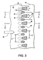
- FIG. 3 illustrates in more detail the common row or radial column of multiform holes 34, 36 extending through the airfoil.
- the multiform holes 34, 36 are specifically configured differently from each other for complementing the cooling performance thereof in the single or common longitudinal row extending along the airfoil span.
- the first holes 34 are generally tubular or cylindrical and extend straight through the sidewall 18.
- the second holes 36 have a different form than the first holes and in one embodiment are in the form of diverging diffusion film-cooling holes, which may have any conventional configuration.
- FIGS. 4 and 5 illustrate in sectional view the different forms of the first and second holes 34, 36 which extend through the common sidewall 18 between the inside or inboard surface 38 thereof and the external or outboard surface 40 thereof.
- the tubular first hole 34 illustrated in FIG. 4 is in one embodiment inclined through the sidewall 18 at a shallow inclination angle A of about 30 degrees for example.
- the diffusing second hole 36 is different in form than the cylindrical first hole 34, and is also inclined through the sidewall 18 at a corresponding inclination angle B.
- Each of the first holes 34 illustrated in FIG. 4 includes a corresponding first inlet 42 in the form of an aperture in the inboard surface 38 of the sidewall, and a longitudinally opposite first outlet 44 in the form of an aperture in the outboard surface 40 of the airfoil.
- Each of the second holes 36 illustrated in FIG. 5 includes a corresponding second inlet 46 in the form of an aperture in the inboard surface 38, and a larger second outlet 48 in the form of an aperture in the outboard surface 40.
- the first and second holes 34, 36 illustrated in FIGS. 3 5 may each have any conventional configuration, and may further provide enhanced performance in the commingled row thereof.
- the cylindrical first holes 34 are inclined through the sidewall 18 and create oval or elliptical first inlets 42 and outlets 44 on the opposite inboard and outboard surfaces due to the inclination angle thereof.
- the second holes 36 may have cylindrical second inlets 46 extending in forward part through the sidewall, and the holes 36 diverge in aft part through the sidewall to a generally trapezoidal second outlet 48 on the outboard surface.
- the cylindrical portions of the two sets of holes 34, 36 may be substantially identical in diameter or flow area, with the first and second inlets 42, 46 and the first outlet 44 being substantially identical in form and flow area if desired. Alternately, they may differ in these aspects, in any combination.
- the first and second holes 34, 36 may be similarly inclined through the sidewall 18 at corresponding longitudinal inclination angles A, B which may, for example, be equal to each other and about 30 degrees. Alternately, they may differ in these aspects, in any combination.
- the second holes 36 diverge longitudinally aft from their cylindrical inlets at a shallower inclination angle C at or near the corresponding second outlets 48 in the outboard surface 40.
- the inclination angle C of the hole outlet may be about 15 degrees, for example, which permits diffusion of the cooling fluid 28, such as cooling air, in the aft direction and smooth blending thereof with the exposed outboard surface 40 downstream therefrom.
- the exemplary trapezoidal outlet 48 is symmetrical and has diverging sides, each having a suitably small diffusion angle of about 7.5 degrees for example which cooperates with the shallow inclination angle C in a conventional manner.
- the tubular inlet portions thereof meter the discharge of the pressurized cooling air 28 from the internal cooling circuit of the airfoil.
- the diverging diffusion outlets 48 of the second holes 36 reduce the discharge velocity therefrom and laterally spread the film-cooling air in the span direction as illustrated schematically in FIG. 3 .
- a relatively high velocity jet of cooling air may be discharged from the cylindrical first holes 34 in the same flow direction as the combustion gases, and between the corresponding relatively low velocity jets of film-cooling air discharged from the adjacent second holes 36.
- the different forms of the two film-cooling holes, the different performance thereof, and the different distribution of the cooling air jets discharged therefrom may be used to complement the performance therebetween for affecting a collective film of cooling air discharged downstream from the common lateral row thereof.
- film-cooling holes discharge jets of cooling air that have film-cooling effect which extends downstream therefrom with a narrow lateral distribution in the radial span direction.
- the two forms of film-cooling holes may be packed with a corresponding collective density thereof and corresponding coverage or footprint of the corresponding outlets thereof for enhancing both the downstream or aft effectiveness of the collective film of cooling air as well as the lateral effectiveness of the film-cooling air from hole to hole along the longitudinal extent of the common row thereof.
- the different forms of the first and second outlets 44, 48 permit complementary coverage between the two types of holes, and the two types of holes may be conventionally manufactured using less expensive laser drilling for the cylindrical holes 34 and more expensive electric discharge machining (EDM) machining for the shaped diffusion holes 36. Accordingly, instead of using a full row of the diffusion holes 36 alone, and their attendant high cost, the diffusion holes may be alternated with the less expensive laser drilled holes 34 for reducing cost of the airfoil, as well as enhancing performance of the pressurized cooling air discharged from the common row of multiform holes.
- EDM electric discharge machining
- the individual film-cooling holes 34 and 36 may have any suitable conventional configuration thereof, the former without diffusion and the latter with diffusion, and arranged in a common row laterally side-by-side for complementing the configuration and performance thereof.
- FIG. 3 illustrates that the first outlets 44 are colinearly aligned with the second outlets 48 along the radial or longitudinal span of the sidewall, with the upstream ends of the two different outlets being generally aligned with each other. Since the two outlets have different forms, the downstream ends thereof may or may not be similarly aligned.
- FIGS. 1-5 are merely illustrative of one embodiment of film-cooling in a turbine blade airfoil.
- Many other turbine blade airfoil configurations already exist that incorporate film-cooling with a vast array of film-cooling hole patterns, sizes, shapes and orientations, and many new turbine blade airfoil configurations with film-cooling are possible, with a corresponding vast array of potential film-cooling hole patterns, sizes, shapes and orientations.
- FIGS. 1-5 also illustrate schematically that film-cooling holes, including multiform holes 34, 36, may also be used in a hollow vane airfoil 50 of a turbine stator nozzle in which opposite pressure and suction sides thereof extend between chordally opposite leading and a trailing edges and between radially outer and inner bands (not shown).
- Nozzle vanes, particularly first stage nozzle vanes, are also typically partially hollow and provided with internal cooling circuits which discharge the spent cooling air through various rows or other configurations or patterns of film-cooling holes through the sidewalls (pressure or suction) thereof.
- FIG. 1 also illustrates schematically that film-cooling holes, including multiform holes 34, 36, may also be used to provide film-cooling through the sidewall to the airfoil surface of a typical annular inner or outer combustion liner 52, as desired, in any region of the liner airfoil surface where film-cooling is desired.
- turbine shrouds 54 surround the radially outer tips of the turbine blade and typically also include film-cooling through the sidewall to the shroud airfoil surface.
- the multiform holes 34, 36 may also be introduced in the turbine shrouds 54 as desired in lieu of conventional patterns of film-cooling holes.
- the film-cooling improvements described herein are believed to be applicable to these and any other gas turbine airfoil surfaces 56, including combustors, nozzles and disks, that are exposed to hot combustion gases such that film-cooling is desirable, including, without limitation, application to airfoil surfaces within the compressor and other airfoil surfaces associated with the turbine.
- turbine airfoil 12 includes a plurality of typical cylindrical film-cooling holes 30 in the leading edge and in suction and pressure sidewalls, as well as a plurality of trailing edge cooling holes 32, and a plurality of multiform cooling holes 34, 36, as described herein.
- These film-cooling holes have a corresponding plurality of film-cooling hole inserts 100 disposed in the film-cooling holes.
- Inserts 100 include a body 110 that is configured for disposition in the film-cooling hole. Insert body 110 has a proximal end 112 configured for disposition proximate the airfoil surface 21 and an opposed distal end 114.
- Insert 100 may be located at any location within the film-cooling hole in which it is disposed. By describing insert 100 as having its proximal end 112 proximate the airfoil surface 21 and outlet 33, it is merely meant that this end is located most closely to the airfoil surface 21. Similarly, by describing insert 100 as having its distal end 114 proximate the cooling circuit within airfoil 12 or inlet 31, it is merely meant that this end is located most closely to the cooling circuit 24 and inlet 31.
- proximate should not be interpreted as requiring that the proximal end 112 of insert 100 be located at or immediately adjacent to the airfoil surface 21 or outlet 33, or that distal end 114 be located at or immediately adjacent to the cooling circuit 24 or inlet 31. Rather, insert 100 may be located with distal end 114 anywhere within the film-cooling hole ( FIG. 4 ), including at locations where distal end 114 of one or more inserts 100 is located at or adjacent to the inlet 31 of the film-cooling hole ( FIG. 5 ).
- insert 100 may be located with proximal end 112 anywhere within the film-cooling hole, including at locations where proximal end 112 of one or more inserts 100 is located with proximal end 112 at or adjacent to the outlet 33 of the film-cooling hole ( FIGS. 3-5 ). Furthermore, one or more inserts 100 may extend and be located at or adjacent to both inlets 31 and outlets 33, as illustrated in FIG. 5 . Even further, one or more inserts 100 may project beyond either inlet 31 or outlet 33, such that some or all of them project inwardly into the internal cooling circuit 24 of the airfoil 12, or outwardly of the airfoil surface 21, respectively.
- Inserts 100 also include one or more passageways 116 configured for receipt of the cooling fluid 28, such as cooling air, that replaces the passageway that would otherwise exist by virtue of the existence of the film-cooling hole. It is by alteration of this passage to create passageway (or passageways) 116 that the advantages described above with regard to the use of insert 100 to alter the characteristic airflow within and cooling characteristics of the film-cooling hole may be achieved.
- Passageway (or passageways) 116 extend between the proximal end 112 and distal end 114 of insert 100 in a continuous fashion such that it provides fluid coupling and a fluid flow passageway for cooling fluid 28 to flow from the inlet 31 to the outlet 33 of the film-cooling hole.
- the body 110 may be used to divide the volume of the film-cooling hole and define a passageway 116 or passageways 116, or alternately, the body 110 may itself include one or more passageways 116 that may be inserted into the film-cooling hole.
- passageway 116 may include a single passageway, or a plurality of passageways 116 through body 110. In the exemplary embodiment of FIGS. 1-5 , both a single passageway 116 and a plurality of passageways 116 are illustrated.
- some of the inserts 100 include a body 110 of a sintered powder compact 102 having a porous structure comprising a network of interconnected particles and a corresponding complementary network of interconnected, inter-particle, interstitial spaces, analogous to various types of sintered powder compact filter media, as shown in FIGS. 2-5 schematically by stippling.
- the interconnected, interstitial spaces provide the plurality of passageways 116, as they provide multiple fluid flow paths through the body, and a tortuous path for the cooling fluid, thereby promoting enhance heat transfer thereto.
- the sintered powder compact may be any suitable sintered powder compact.
- sintered powder compact may include a sintered metal powder compact, wherein the metal compact has a continuous network of interconnected, interstitial spaces between sintered metal particles or agglomerated groups of particles.
- any suitable metal powder or powders may be used. Suitable metals include Cu, Al, Ag or Ni or various Cu-based alloys, Al-based alloys, Ag-based alloys or Ni-based alloys, and the like, in any combination.
- This network provides a plurality of passageways 116 through insert 100 from the proximal end 112 to the distal end 114.
- This network of passageways 116 may be used to conduct the cooling air through insert 100. Due to the enhanced surface area of such a structure over that of the film-cooling hole into which it is disposed, the heat transfer coefficient will also be greater than that of a film-cooling hole of the same diameter. In addition to an enhanced heat transfer coefficient, insert 100 also increases the pressure drop across the film-cooling hole from the inlet 31 to the outlet 33. Inserts 100, including sintered powder compacts, also provide more surface area for heat transfer, which also contributes to the increased heat transfer coefficient associated with the film-cooling hole.
- the sintered powder compact may also be selected to have a melting point that is lower than the melting point of the airfoil, such as airfoil 12. Therefore, should plugging of some or all of the passageways occur, leading to a localized overheating condition within airfoil 12 at locations proximate the obstructed film-cooling hole, the sintered powder compact will at least partially melt, thereby allowing the insert to be ejected by the air pressure within the cooling circuit and clearing the film-cooling hole in which it is disposed, thus restoring cooling within the film-cooling hole in airfoil 12 at that location.
- Sintered powder compact inserts may be formed in place within the airfoil 12, such as by insertion of green powder performs (not shown) into film-cooling holes and heating the airfoil 12 to sinter the preforms producing sintered powder compact inserts 100.
- the powder of the preforms will have a sintering temperature that is compatible with the airfoil 12, such that sintering does not degrade the properties of airfoil 12.
- sintered powder compact may be sintered separately, and then inserted into the film-cooling hole to the desired depth and orientation followed by attachment to the wall 120 of the film-cooling hole, such as by brazing or the other attachment methods described herein.
- body 110 may be inserted into holes of any shape, including cylindrical holes and multi-form holes 34, 36 having various non-cylindrical shapes, or including various tapers or other features at either the inlet 31 or outlet 33 of the holes.
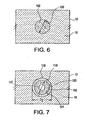
- a sintered powder compact is shown within a film-cooling hole in a cross-sectional view taken orthogonally to the longitudinal axis of the film-cooling hole.
- sintered powder compact may be configured to completely fill the film-cooling hole, such that the only passageway through insert 100 and body 110 is through the plurality of passageways 116 that include the interconnected, interstitial spaces between the sintered powder particles.
- film-cooling hole may have a diameter (D 1 ) ( FIG. 6 ).
- This diameter may be the existing design diameter of the film-cooling hole in the case of existing airfoil designs, or in the case of new airfoil designs incorporating the inserts disclosed herein, the diameter may be designed with the particular airflow characteristics of the sintered powder and insert 100 being used.
- the diameter (D 1 ) may be selected in view of the airflow, and particularly the pressure drop, heat transfer and other characteristics, associated with powder metal compact insert 100. This principle may also be utilized with respect to all of the types of inserts 100 disclosed herein. Referring to FIG.
- the film-cooling hole diameter may also be adjusted in embodiments that also include a casing 118, the film-cooling hole may be made slightly oversized to a diameter (D 2 ) in order to accommodate the outer diameter of casing 118, while the inner diameter of casing 118 may be sized to achieve the desired diameter (D 1 ) of the passageway 116.
- Casing 118 may be made from any suitable material, including various pure metals and metal alloys. Suitable pure metals and metal alloys include Cu and Cu-based alloys, Al and Al-based alloys, Ni and Ni-based alloys Ag and Ag-based alloys and the like, and combinations thereof.
- Sintered powder compact may also include, in addition to the plurality of passageways 116 described above, an additional passageway 116 comprising a through-hole or other through passageway other than the plurality of passageways formed within the sintered powder compact as described above.
- the diameter of the passageway may be sized to achieve the design objectives for the flow of cooling air through the film-cooling hole in which it is used, such as to achieve a particular pressure drop across the film-cooling hole, or a particular film-cooling pattern at the outlet 33 of the insert 100, or similar design objectives related to the film-cooling hole, such as the heat transfer coefficient (including contribution of insert 100) or film-cooling pattern produced through the film-cooling hole or the like.
- Casing 118 has an outer surface 119 and inner surface 121. In the embodiment shown, sintered powder compact 102 is disposed within and attached to inner surface 121. Outer surface 119 is disposed within and attached to wall 120 of the film-cooling hole.
- inserts 100 may also include a metal foam, where the metal foam is also configured to have a porous structure including an open cell foam network of interconnected, interstitial pores or spaces between the matrix metal that extends from proximal end 112 to distal end 114 of body 110, wherein the interconnected, interstitial pores and open cell foam network form a plurality of passageways 116 through which the film-cooling fluid may flow.
- Inserts 100 that include a metal foam may be disposed in the film-cooling holes by any suitable method, including forming inserts 100 in a separate metal foam, forming operation, followed by insertion into the film-cooling holes and attachment by brazing or the other attachment methods described herein.
- body 110 that includes a metal foam may also be disposed within a suitable casing 118, such as a tubular casing as shown in FIG. 7 .
- Body 110 that includes metal foam disposed within casing 118 may be disposed within a film-cooling hole (30, 32, 34 or 36) and attached to the wall 120 thereof by brazing, or another of the attachment methods described herein.
- inserts 100 may be formed from any material that is suitable for use at the application temperatures of turbine airfoil 12 in the regions where the use of inserts 100 have been described herein. These materials include various pure metal and metal alloy, as described herein. In conjunction with the schematic illustrations of FIGS. 8-15 , these are sectioned as metals, but as indicated above, any suitable material may be used for insert 100.
- an insert 100 for a trailing edge film-cooling hole 32 may have a passageway 116 that includes a tortuous path passageway 116, such as the step or zigzag pattern illustrated.
- a tortuous path passageway 116 such as the step or zigzag pattern illustrated.
- Such a pattern causes a portion of the cooling fluid 28 flowing through passageway 116 at the inflections or corners in the passageway 116 to be forced into the sidewall, thereby producing localized turbulence along the length of passageway 116 and enhancing heat transfer associated with the passage of cooling fluid 28 through passageway 116 having this configuration.
- the surface area associated with the tortuous path described is greater than the surface area of the sidewall in a passageway 116 of the same diameter, which extends straight through insert 100.
- FIG. 8 has a passageway access 124 having a stepped configuration as shown in FIG. 8 .
- a passageway 116 having a curved profile rather than the sharp steps shown in FIG. 8 .
- the sharp steps of FIG. 8 have a radius of curvature associated therewith.
- insert 100 may also include a longitudinally extending rib 126.
- Rib 126 may extend along the entire length of the film-cooling hole, or only partially along the length thereof, as described herein. Rib 126 may be made from any suitable material, including various pure metals and metal alloys, as described herein. Rib 126 divides the film-cooling hole into two passageways 116. Rib 126 may have the flat plate-like configuration as shown, or alternately may have a series of twists therein, such as helical twists, in order to promote redirection of the cooling fluid 28 as it flows within passageways 116.
- rib 126 may include one or more lateral protrusions 128 that extend into passageways 116, and which function as turbulators.
- the lateral protrusions 128 may have any suitable shape and be provided in any suitable number. In an exemplary embodiment, they may be formed by piercing the rib along its length followed by bending of the pierced portion outwardly lateral to the longitudinal axis of the rib, and similar to that shown with respect to lateral protrusions illustrated within FIG. 13 . Where lateral protrusions are formed by piercing, the piercing and bending operation also forms openings through the rib between passageways 116, further enhancing turbulence and mixing of the cooling fluid as it passes through passageways 116. Alternately, lateral protrusions may be formed to simply extend from a continuous metal rib (not shown), and may be made, for example, by casting, drawing or similar metal forming processes.
- insert 100 may include a body 110 comprising a plurality of ribs 126. These ribs 126 may be used to define multiple passageways 116 within the film-cooling hole. Ribs may be disposed in the film-cooling hole in the manner described above with respect to a single rib, and may be made from the same materials as described with respect to the single rib 126, or as otherwise described herein. Similarly, ribs 126 may also include one or more lateral protrusions 128 which act as turbulators promoting the turbulent flow of cooling fluid within passageways 116, and enhancing the heat transfer coefficient associated with the film-cooling hole in which it is located in the manner described herein. Lateral projections 128 may be formed in the same manner as described herein with respect to the single rib shown in FIG. 9 .
- insert 100 may include a plurality of through-holes formed through body 110, where the through-holes extend from the proximal end 112 to the distal end 114 thereof and form a plurality of passageways 116.
- the number of through-holes and their diameter, shape, length and other characteristics may be selected to achieve the desired increase in the heat transfer coefficient associated with the body 110 in the film-cooling hole in which it is disposed, as well as to increase the surface area over which this heat transfer may occur.
- the through-holes forming passageway 116 may have the shape of a longitudinally extending slot (or slots). Additionally, depending on the shape of the through-holes desired, it may be desirable from the standpoint of the structural integrity of the body 110 to incorporate a casing 118, as shown in FIG. 12 .
- insert 100 and body 110 may include a casing 118 as described herein.
- Casing 118 may include a metal or metal alloy, as described herein.
- passageway 116 is formed by the inner diameter of casing 118.
- One or more lateral protrusions 128 may be formed by piercing casing 118 and bending pierced portions inwardly into passageway 116. Lateral protrusions 128 function as turbulators promoting turbulence in the cooling fluid flowing through passageway 116. Lateral protrusions 128 may be formed in any pattern or distribution of locations around the circumference and along the length of casing 118.
- the number and pattern of lateral protrusions may be selected to provide the desired heat transfer coefficient, pressure drop and other design objectives, as described herein, with respect to the film-cooling hole.
- the lateral protrusions 128 may also be formed so as to extend outwardly from casing 118 (not shown), and passageway 116 may also be formed along the outer diameter and outer surface 119 of casing 118.
- the protrusions may be designed so as to be used for attachment of insert 100 and body 110 within the film-cooling hole.
- the lateral protrusions 128 may be attached to the sidewall 120 of the film-cooling hole.
- lateral protrusions 128 may be formed to project from both the outer surface119 and inner surface 121 of casing 118, such that passageways 116 are formed both along the outer surface 119 and inner surface 121 of casing 118 (not shown).
- insert 100 and body 110 may have any suitable shape or size, and may be selected so as to require non-conventional film-cooling hole configurations.
- the rectangular profile of insert 100 would require a corresponding rectangular film-cooling hole, which may be referred to as a film-cooling slot.
- a film-cooling slot Such an arrangement could be utilized, for example, along the trailing edge of airfoil 12.
- Body 110 may be made from any of the materials described herein including various pure metals or metal alloys, as described herein. Further, body 110 may be disposed within the film-cooling hole or slot in the manner described herein with respect to other embodiments of body 110.
- Body 110 includes a plurality of passageways 116 having a tortuous path from the proximal end 112 to the distal end 114, but otherwise is analogous to the exemplary embodiment of FIG. 8 .
- the passageways 116 may have a stepped or curved profile as described with respect to the embodiment of FIG. 8 .
- the passageways 116 may also include a tapered lead-in 117 to promote the flow of cooling fluid 28 into passageway 116.
- a tapered lead-in may be used in any of the exemplary embodiments of insert 100 illustrated herein, including the embodiment of FIG. 8 .
- the lead-in may be tapered or have any other shape suitable to promote the flow of cooling fluid 28 into passageway 116.
- insert 100 While some of the embodiments of insert 100 described herein have been described as being capable of being formed in place within a film cooling hole, any of the embodiments described herein may be manufactured as discreet components and inserted into and attached to a film cooling hole by a suitable attachment means, including various brazes, various forms of metallurgical bonding, adhesives, cements and the like. As indicated herein, insert 100 may be selected such that it has a melting temperature which is less than the melting temperature of the surrounding sidewall of the airfoil, as well as less than a melting or working temperature of the attachment means, such as a braze, various forms of metallurgical bonding or adhesive.
- insert 100 in the event of blockage of film cooling hole, is the lowest melting component such that it may be cleared by pressure of the cooling fluid 28 and ejected from the film cooling hole, to ensure that film cooling is restored and will avoid over temperature conditions within the airfoil.
- insert 100 may be selected with a melting temperature that is higher than that of the attachment means, including those described above.
- the attachment means such as a braze alloy, will melt first.
- insert 100 upon melting of the braze alloy, insert 100 will be ejected by pressure of cooling fluid 28, thereby restoring film cooling within the film cooling hole of interest.
- the attachment means can be selected to release the insert 100 in the manner described above.
Description
- The subject matter disclosed herein relates generally to gas turbine engines, and, more particularly, to a film-cooling augmentation device and turbine airfoil that incorporates the same.
- Gas turbine engines generally include a compressor that pressurizes air that is then mixed with fuel in a combustor for generating hot combustion gases. Energy from these combustion gases is extracted in multiple turbine stages for powering the compressor and producing useful work, typically by powering a fan in an aircraft turbofan application, or by powering an output shaft for marine, industrial and other applications.
- The combustion gases flow along and transfer heat to various components of the turbine engine. These heated components are cooled in part by a cooling system that uses a portion of the pressurized air generated by the compressor in a cooling circuit that extends to the surface of these components to provide film-cooling of their surfaces that are exposed to the hot combustion gases, or that are heated thereby. The film cooled turbine components include the combustor, nozzles, rotor disks, blades, vanes, shrouds, liners and other components.
- The hot combustion gases are initially discharged from the combustor into a stationary high pressure turbine inlet comprising the first stage turbine nozzle which includes an array of circumferentially-spaced, radially-extending stator nozzle vanes that include vane airfoils which extend between inner and outer bands. The vane airfoils are partially hollow and form a part of the cooling circuit and include various rows and other patterns of film-cooling holes extending through their sidewalls for discharging film-cooling air to form a boundary layer over their outer surfaces, particularly at the leading and trailing edges of the airfoils. The other stages of the turbine also include similar nozzles and arrays of vanes.
- The first stage of the turbine also includes a turbine rotor including an array of circumferentially-spaced, radially-extending turbine rotor blades that are attached to an outer portion of a supporting rotor disk. Each blade includes a partially hollow dovetail portion that is attached to a partially hollow turbine airfoil where their hollow portions form a part of the cooling circuit and include various rows and other patterns of film-cooling holes extending through the sidewalls thereof for film-cooling the outer surfaces thereof, particularly at the leading and trailing edges of the airfoil. The other stages of the turbine also include similar rotors disks and arrays of vanes.
- Film-cooling holes are also found in other components of the typical gas turbine engine and are arranged in various patterns for promoting a film-cooling blanket of air over the surfaces that are exposed either directly or indirectly to the hot combustion gases. The film-cooling holes are frequently arranged in linear rows, with the rows being spaced laterally apart for distributing the film-cooling air as required for accommodating the local heat loads from the combustion gases and forming the blanket of cooling air.
-
US 2008/0203236 describes an airfoil for use in a gas turbine engine including a ceramic matrix composite (CMC) element that extends to define a leading edge portion and chord portion of the airfoil, and a separately formed but conjoined trailing edge element that defines a desirably thin trailing edge of the airfoil without the need for using an excessively small bend radius for reinforcing fibers in the CMC element. The trailing edge element may include a plurality of interlock elements that extend through the trailing edge attachment wall of the CMC element and provide mechanical attachment there between. Alternatively, the trailing edge element may be adhesively bonded or sinter bonded to the CMC element. A cooling air insert may be disposed within a cooling air cavity of the CMC element and may include cooling tubes that extend into the trailing edge element to deliver cooling air there through. -
US2006/226290 describes a vane assembly formed by a forward airfoil segment and an aft airfoil segment. The aft segment is made of metal and defines the trailing edge of the vane assembly. The forward segment can be made of ceramic, CMC or metal. The forward and aft segments cannot be directly joined to each other because of differences in their rates of thermal expansion and contraction. The forward and aft segments are positioned substantially proximate to each other so as to form a gap therebetween which is substantially sealed by providing a coupling insert or leaf springs in the gap. A separate metal aft segment can take advantage of the beneficial thermal properties of the metal to improve cooling efficiency at the trailing edge without limiting the rest of the vane to being made out of metal. - A typical film-cooling hole is tubular or cylindrical and manufactured by laser drilling for example. Another form of film-cooling hole is the diffusion hole which has various configurations in the art. In the diffusion hole the outlet portion thereof diverges or increases in flow area in the downstream aft direction from the upstream inlet for reducing the discharge velocity therefrom. An exemplary diffusion hole has a trapezoidal outlet with side edges which diverge at a suitably small diffusion angle, and an inner land which blends with the component outboard surface at a shallower inclination angle than the nominal inclination angle through the inlet portion of the hole. In this way, the typical diffusion hole is effective for laterally spreading the discharged cooling air jet and locally enhancing film-cooling performance.
- The configuration, quantity, and pattern of the film-cooling holes, including their cross-sectional shape, length and angle with the surface to be cooled are specifically designed for the expected heat load, which varies from component to component and over the outboard surface of an individual component. Generally, film-cooling hole design, including size, shape, pattern, location and other aspects, has as an objective reduction of the amount of film-cooling air bled from the compressor, since use of such air for film-cooling prevents its use in the combustion process and thus reduces efficiency of the engine.
- The performance of film-cooling holes is affected by many factors, including their geometry including their surface area, and the local conditions in the specific components including the differential pressure or pressure ratio between the outboard and inboard sides of the film-cooling holes, and the velocity and pressure distribution of the combustion gases over the outboard surfaces.
- While film-cooling holes, including diffusion holes, are useful to provide film-cooling in the manner noted above, the ability to control the pressure differential or pressure ratio between the outboard and inboard sides of the film-cooling holes and the airflow through them, as well as the amount of convective cooling of the airfoil sidewall adjacent to the hole have generally been limited to control of the characteristics of the holes themselves, such as their location, spacing, size, shape, orientation (e.g., orientation of the hole inlet to the cooling circuit and angle with the airfoil surface), number and the like, which are in turn have been limited by the manufacturing methods used to create them and other considerations, such as the overall performance requirements of the airfoil.
- Accordingly, it is desired to provide improved methods of cooling gas turbine engine components from the film-cooling holes utilized therein.
- The present invention resides in inserts according to claim 1.
- These and other advantages and features will become more apparent from the following description taken in conjunction with the drawings.
- The subject matter which is regarded as the invention is particularly pointed out and distinctly claimed in the claims at the conclusion of the specification. The foregoing and other features, and advantages of the invention are apparent from the following detailed description taken in conjunction with the accompanying drawings in which:
-
FIG. 1 is a perspective view of an exemplary turbine air foil as described herein; -
FIG. 2 is a cross-sectional view of the turbine air foil ofFIG. 1 taken along section 2-2; -
FIG. 3 is a top view ofregion 3 ofFIG. 1 ; -
FIG. 4 is a cross-sectional view taken along section 4-4 ofFIG. 3 ; -
FIG. 5 is a cross-sectional view taken along section 5-5 ofFIG. 3 ; -
FIG. 6 is a cross-sectional view of an exemplary embodiment of a film-cooling insert as described herein; -
FIG. 7 is a cross-sectional view of a second exemplary embodiment of a film-cooling insert as described herein; -
FIG. 8 is a cross-sectional view of section 8-8 ofFIG. 1 illustrating a third exemplary embodiment of a film-cooling insert as described herein; -
FIG. 9 is a cross-sectional view of a fourth exemplary embodiment of a film-cooling insert as described herein; -
FIG. 10 is a cross-sectional view of a fifth exemplary embodiment of a film-cooling insert as described herein; -
FIG. 11 is a cross-sectional view of a sixth exemplary embodiment of a film-cooling insert as described herein; -
FIG. 12 is a seventh exemplary embodiment of a film-cooling insert as described herein; -
FIG. 13 is a perspective view of an eighth exemplary embodiment of a film-cooling insert as described herein; -
FIG. 14 is a perspective view of a ninth exemplary embodiment of a film-cooling insert as described herein; and -
FIG. 15 is a cross-sectional view of section 15-15 ofFIG. 14 . - The detailed description explains embodiments of the invention, together with advantages and features, by way of example with reference to the drawings.
- Film-cooling holes are widely used in modem gas turbines to cool the turbine airfoils that are exposed to the hot combustion gases during operation of the turbine. The film-cooling holes provide cooling of the airfoil in several ways. Firstly, they provide film-cooling of the airfoil surface. Film-cooling is the cooling of a body or surface by maintaining a thin fluid layer over the affected area of a fluid that has a lower temperature than the operating environment. The fluid film insulates the film-cooled surface from the external operating environment, thereby reducing convective heat transfer from the external operating environment into the airfoil. Further, the film of the cooling fluid also removes heat from the airfoil surface. Secondly, film-cooling also provides convective heat transfer from and cooling of the airfoil sidewall surrounding the film-cooling hole as the cooling air passes flows through it along the length of the hole. Thirdly, the film-cooling hole removes heat by providing an exhaust path for the cooling air that has been heated as it in turn cools the airfoil by passage through the airfoil cooling circuit.
- Referring to
FIGS. 1-15 , several exemplary embodiments of film-coolinginserts 100 for a turbine airfoil are disclosed. Film-coolinginserts 100 are advantageous in that they may be used to provide one or more of an increase in the pressure drop across (i.e., along the length of) the film-cooling holes, an increase in the heat transfer coefficient associated with or attributable to the film-cooling holes, an increase of the surface area of the holes over which heat transfer occurs, an improvement of the film pattern and the film-cooling associated with the film-cooling hole, a reduction of the tendency of the film holes to plug with ash and other particulate constituents found in the hot combustion gas environment to which the airfoils are exposed, or provision of a film-cooling scheme that is self-healing in the event that the cooling passages associated with the insert become plugged. The film-cooling holes may be drilled somewhat larger than normal to accommodate theinserts 100. Theinserts 100 create a more tortuous path for air flowing through the film-cooling hole, thereby providing the advantages described above. Theinserts 100 may also include a feature at the outlet of the hole to protect the hole from ingesting particulates from the hot gas stream. The insert can also have a feature at the outlet of the hole to direct the film against the surface of the airfoil or otherwise control the shape of the cooling film exiting the film-cooling hole. Either the insert or the material used to attach the insert may have a melting temperature that is lower than that of the airfoil sidewall so that if the film-cooling passage within the insert becomes plugged, the temperature increase that results from the lack of cooling through the passage will cause the insert or the attachment material to melt, such that the pressure of the coolant will cause the insert to be ejected from the film-cooling hole, thereby eliminating the blockage and restoring film-cooling through the film-cooling hole. This self-clearing feature will provide additional film-cooling to alleviate the localized heating described above. The insert may be made of a material with a melting temperature such that it is solid in the film-cooling hole, but liquid after leaving the film hole and being exposed to the hot combustion gases. The insert may also be used to repair parts, or modify the film-cooling characteristics of an existing airfoil design (including an existing film-cooling holes of a defined size, shape, orientation, pattern, etc.) by selective incorporation of film-cooling inserts as described herein. - An exemplary component of a gas turbine engine having an airfoil that employs film-cooling in the form of a
turbine rotor blade 10 is illustrated inFIG. 1 . The rotor blade includes anairfoil 12 integrally joined to aplatform 14 at the root thereof which in turn is joined to a supporting axial-entry dovetail 16 for mounting the blade to the perimeter of turbine rotor disk (not shown) in a conventional manner. - As additionally shown in
FIG. 2 , the airfoil is hollow and is bounded by athin sidewall 18 which defines a generallyconcave pressure side 17 of the airfoil and an opposite, generallyconvex suction side 19 of theairfoil 12 which extend chordally in the axial downstream direction between aleading edge 20 and anopposite trailing edge 22. - The airfoil includes an
internal cooling circuit 24 which may have any conventional configuration and typically includes radially extending channels separated by radial partitions bridging the two sides of the airfoil in one or more dedicated circuits, typically including multi-pass serpentine circuits as conventionally known. - During operation,
combustion gases 26 are generated in a combustor (not shown) and flow downstream over the outer surface of theairfoil 12.Pressurized cooling air 28 is bled from a compressor (not shown) and suitably channeled through inlet apertures extending radially through theblade dovetail 16 to feed theinternal cooling circuit 24. - The internal cooling circuit for the blade illustrated in
FIG. 1 may be configured as desired for cooling the different portions of the airfoil between the leading and trailing edges, and typically includes various radial rows of conventional film-cooling holes 30 extending through the pressure and suction sides thereof for discharging the coolingair 28 from theinternal cooling circuit 24. Thethin trailing edge 22 of the airfoil is also typically cooled by a row of pressure-side trailing edge cooling holes 32 in any conventional configuration. - In the exemplary embodiment illustrated in
FIGS. 1 and2 , the film-cooling holes 30 are arranged in various rows around the leading edge region of the airfoil in conventionally known showerhead and gill hole configurations. In this way, the specifically configured film-cooling holes provide local cooling of the different portions of the leading edge on the pressure and suction sides thereof to accommodate the different thermal loads from the combustion gases which flow over the pressure and suction sides of the airfoil with different pressure and velocity distributions. - The exemplary film-
cooling holes 30 are typically generally cylindrical or tubular holes inclined through the airfoil sidewall at various inclination angles relative to the changing profile of the airfoil around the leading edge for effecting film-cooling thereof. The term generally cylindrical includes various flattened cylindrical shapes, as well as various conduits having an elliptical or semi elliptical cross-section. Generally, holes 30 are oriented to discharge the coolant, such as cooling air, aft toward the trailing edge in the same direction as that of the combustion gases flowing over the surface of the airfoil; however, orientation so as to provide countercurrent discharge in the direction of the leading edge is also known and within the scope of this disclosure. -
FIGS. 1 and2 also illustrate film-cooling holes having an alternate form in an exemplary hole pattern at an exemplary location along the pressure side of the airfoil, although these holes may be located in any suitable pattern or location in the airfoil sidewall, or other turbine engine components having airfoil surfaces that require film-cooling. More specifically, thesidewall 18, or simply sidewall, of the airfoil is relatively thin and bounds theinternal cooling circuit 24. Thesidewall 18 may also include a common row or rows of laterally alternating multiform film-cooling holes internal cooling circuit 24 for receiving thepressurized cooling air 28 first used for inside cooling the airfoil. Generally, holes 34, 36 are also oriented to discharge the coolant, such as cooling air, aft toward the trailing edge in the same direction as that of the combustion gases flowing over the surface of the airfoil; however, orientation so as to provide countercurrent discharge in the direction of the leading edge is also possible and within the scope of this disclosure. - The film-cooling
first holes 34 are arranged colinearly along the radial span of the airfoil in a row generally normal to the downstream direction of the combustion gases. And, the film-coolingsecond holes 36 are also arranged colinearly along the span of the airfoil in a common row with thefirst holes 34, and alternate laterally with respective ones thereof. -
FIG. 3 illustrates in more detail the common row or radial column ofmultiform holes multiform holes first holes 34 are generally tubular or cylindrical and extend straight through thesidewall 18. Thesecond holes 36 have a different form than the first holes and in one embodiment are in the form of diverging diffusion film-cooling holes, which may have any conventional configuration. -
FIGS. 4 and 5 illustrate in sectional view the different forms of the first andsecond holes common sidewall 18 between the inside orinboard surface 38 thereof and the external oroutboard surface 40 thereof. The tubularfirst hole 34 illustrated inFIG. 4 is in one embodiment inclined through thesidewall 18 at a shallow inclination angle A of about 30 degrees for example. The diffusingsecond hole 36 is different in form than the cylindricalfirst hole 34, and is also inclined through thesidewall 18 at a corresponding inclination angle B. - Each of the
first holes 34 illustrated inFIG. 4 includes a correspondingfirst inlet 42 in the form of an aperture in theinboard surface 38 of the sidewall, and a longitudinally oppositefirst outlet 44 in the form of an aperture in theoutboard surface 40 of the airfoil. - Each of the
second holes 36 illustrated inFIG. 5 includes a correspondingsecond inlet 46 in the form of an aperture in theinboard surface 38, and a largersecond outlet 48 in the form of an aperture in theoutboard surface 40. - The first and
second holes FIGS. 3 5 may each have any conventional configuration, and may further provide enhanced performance in the commingled row thereof. For example, the cylindricalfirst holes 34 are inclined through thesidewall 18 and create oval or ellipticalfirst inlets 42 andoutlets 44 on the opposite inboard and outboard surfaces due to the inclination angle thereof. - The
second holes 36 may have cylindricalsecond inlets 46 extending in forward part through the sidewall, and theholes 36 diverge in aft part through the sidewall to a generally trapezoidalsecond outlet 48 on the outboard surface. - The cylindrical portions of the two sets of
holes second inlets first outlet 44 being substantially identical in form and flow area if desired. Alternately, they may differ in these aspects, in any combination. - As shown in
FIGS. 4 and 5 , the first andsecond holes sidewall 18 at corresponding longitudinal inclination angles A, B which may, for example, be equal to each other and about 30 degrees. Alternately, they may differ in these aspects, in any combination. In the embodiment shown inFIGS. 4 and 5 , thesecond holes 36 diverge longitudinally aft from their cylindrical inlets at a shallower inclination angle C at or near the correspondingsecond outlets 48 in theoutboard surface 40. - The inclination angle C of the hole outlet may be about 15 degrees, for example, which permits diffusion of the cooling
fluid 28, such as cooling air, in the aft direction and smooth blending thereof with the exposedoutboard surface 40 downstream therefrom. As shown inFIG. 3 , the exemplarytrapezoidal outlet 48 is symmetrical and has diverging sides, each having a suitably small diffusion angle of about 7.5 degrees for example which cooperates with the shallow inclination angle C in a conventional manner. - In both forms of film-
cooling holes FIGS. 4 and 5 , the tubular inlet portions thereof meter the discharge of thepressurized cooling air 28 from the internal cooling circuit of the airfoil. The divergingdiffusion outlets 48 of thesecond holes 36 reduce the discharge velocity therefrom and laterally spread the film-cooling air in the span direction as illustrated schematically inFIG. 3 . - In this way, a relatively high velocity jet of cooling air may be discharged from the cylindrical
first holes 34 in the same flow direction as the combustion gases, and between the corresponding relatively low velocity jets of film-cooling air discharged from the adjacent second holes 36. - The different forms of the two film-cooling holes, the different performance thereof, and the different distribution of the cooling air jets discharged therefrom may be used to complement the performance therebetween for affecting a collective film of cooling air discharged downstream from the common lateral row thereof.
- As indicated above, film-cooling holes discharge jets of cooling air that have film-cooling effect which extends downstream therefrom with a narrow lateral distribution in the radial span direction. The two forms of film-cooling holes may be packed with a corresponding collective density thereof and corresponding coverage or footprint of the corresponding outlets thereof for enhancing both the downstream or aft effectiveness of the collective film of cooling air as well as the lateral effectiveness of the film-cooling air from hole to hole along the longitudinal extent of the common row thereof.
- Furthermore, the different forms of the first and
second outlets cylindrical holes 34 and more expensive electric discharge machining (EDM) machining for the shaped diffusion holes 36. Accordingly, instead of using a full row of the diffusion holes 36 alone, and their attendant high cost, the diffusion holes may be alternated with the less expensive laser drilledholes 34 for reducing cost of the airfoil, as well as enhancing performance of the pressurized cooling air discharged from the common row of multiform holes. - As indicated above, the individual film-
cooling holes FIG. 3 illustrates that thefirst outlets 44 are colinearly aligned with thesecond outlets 48 along the radial or longitudinal span of the sidewall, with the upstream ends of the two different outlets being generally aligned with each other. Since the two outlets have different forms, the downstream ends thereof may or may not be similarly aligned. - The embodiments of
FIGS. 1-5 are merely illustrative of one embodiment of film-cooling in a turbine blade airfoil. Many other turbine blade airfoil configurations already exist that incorporate film-cooling with a vast array of film-cooling hole patterns, sizes, shapes and orientations, and many new turbine blade airfoil configurations with film-cooling are possible, with a corresponding vast array of potential film-cooling hole patterns, sizes, shapes and orientations. - Due to the similarities of the basic shape of a blade airfoil and a vane airfoil,
FIGS. 1-5 also illustrate schematically that film-cooling holes, includingmultiform holes hollow vane airfoil 50 of a turbine stator nozzle in which opposite pressure and suction sides thereof extend between chordally opposite leading and a trailing edges and between radially outer and inner bands (not shown). Nozzle vanes, particularly first stage nozzle vanes, are also typically partially hollow and provided with internal cooling circuits which discharge the spent cooling air through various rows or other configurations or patterns of film-cooling holes through the sidewalls (pressure or suction) thereof. The film-cooling holes may be conveniently introduced in the nozzle vane at any suitable location around the external surface thereof, analogous to that ofrotor blade 10. Similarly,FIG. 1 also illustrates schematically that film-cooling holes, includingmultiform holes outer combustion liner 52, as desired, in any region of the liner airfoil surface where film-cooling is desired. As also indicated above and illustrated schematically inFIG. 1 , turbine shrouds 54 surround the radially outer tips of the turbine blade and typically also include film-cooling through the sidewall to the shroud airfoil surface. Accordingly, themultiform holes - Referring to
FIGS. 1-5 , and particularly toFIG. 2 ,turbine airfoil 12 includes a plurality of typical cylindrical film-cooling holes 30 in the leading edge and in suction and pressure sidewalls, as well as a plurality of trailing edge cooling holes 32, and a plurality of multiform cooling holes 34, 36, as described herein. These film-cooling holes have a corresponding plurality of film-cooling hole inserts 100 disposed in the film-cooling holes.Inserts 100 include abody 110 that is configured for disposition in the film-cooling hole.Insert body 110 has aproximal end 112 configured for disposition proximate theairfoil surface 21 and an opposeddistal end 114.Insert 100 may be located at any location within the film-cooling hole in which it is disposed. By describinginsert 100 as having itsproximal end 112 proximate theairfoil surface 21 andoutlet 33, it is merely meant that this end is located most closely to theairfoil surface 21. Similarly, by describinginsert 100 as having itsdistal end 114 proximate the cooling circuit withinairfoil 12 orinlet 31, it is merely meant that this end is located most closely to thecooling circuit 24 andinlet 31. The use of proximate should not be interpreted as requiring that theproximal end 112 ofinsert 100 be located at or immediately adjacent to theairfoil surface 21 oroutlet 33, or thatdistal end 114 be located at or immediately adjacent to thecooling circuit 24 orinlet 31. Rather, insert 100 may be located withdistal end 114 anywhere within the film-cooling hole (FIG. 4 ), including at locations wheredistal end 114 of one ormore inserts 100 is located at or adjacent to theinlet 31 of the film-cooling hole (FIG. 5 ). Likewise, insert 100 may be located withproximal end 112 anywhere within the film-cooling hole, including at locations whereproximal end 112 of one ormore inserts 100 is located withproximal end 112 at or adjacent to theoutlet 33 of the film-cooling hole (FIGS. 3-5 ). Furthermore, one ormore inserts 100 may extend and be located at or adjacent to bothinlets 31 andoutlets 33, as illustrated inFIG. 5 . Even further, one ormore inserts 100 may project beyond eitherinlet 31 oroutlet 33, such that some or all of them project inwardly into theinternal cooling circuit 24 of theairfoil 12, or outwardly of theairfoil surface 21, respectively. -
Inserts 100 also include one ormore passageways 116 configured for receipt of the coolingfluid 28, such as cooling air, that replaces the passageway that would otherwise exist by virtue of the existence of the film-cooling hole. It is by alteration of this passage to create passageway (or passageways) 116 that the advantages described above with regard to the use ofinsert 100 to alter the characteristic airflow within and cooling characteristics of the film-cooling hole may be achieved. Passageway (or passageways) 116 extend between theproximal end 112 anddistal end 114 ofinsert 100 in a continuous fashion such that it provides fluid coupling and a fluid flow passageway for coolingfluid 28 to flow from theinlet 31 to theoutlet 33 of the film-cooling hole. - The
body 110 may be used to divide the volume of the film-cooling hole and define apassageway 116 orpassageways 116, or alternately, thebody 110 may itself include one ormore passageways 116 that may be inserted into the film-cooling hole. - As noted,
passageway 116 may include a single passageway, or a plurality ofpassageways 116 throughbody 110. In the exemplary embodiment ofFIGS. 1-5 , both asingle passageway 116 and a plurality ofpassageways 116 are illustrated. Referring toFIGS. 2-5 , some of theinserts 100 include abody 110 of a sintered powder compact 102 having a porous structure comprising a network of interconnected particles and a corresponding complementary network of interconnected, inter-particle, interstitial spaces, analogous to various types of sintered powder compact filter media, as shown inFIGS. 2-5 schematically by stippling. The interconnected, interstitial spaces provide the plurality ofpassageways 116, as they provide multiple fluid flow paths through the body, and a tortuous path for the cooling fluid, thereby promoting enhance heat transfer thereto. The sintered powder compact may be any suitable sintered powder compact. In particular, sintered powder compact may include a sintered metal powder compact, wherein the metal compact has a continuous network of interconnected, interstitial spaces between sintered metal particles or agglomerated groups of particles. For a sintered metal compact, any suitable metal powder or powders may be used. Suitable metals include Cu, Al, Ag or Ni or various Cu-based alloys, Al-based alloys, Ag-based alloys or Ni-based alloys, and the like, in any combination. This network provides a plurality ofpassageways 116 throughinsert 100 from theproximal end 112 to thedistal end 114. This network ofpassageways 116 may be used to conduct the cooling air throughinsert 100. Due to the enhanced surface area of such a structure over that of the film-cooling hole into which it is disposed, the heat transfer coefficient will also be greater than that of a film-cooling hole of the same diameter. In addition to an enhanced heat transfer coefficient, insert 100 also increases the pressure drop across the film-cooling hole from theinlet 31 to theoutlet 33.Inserts 100, including sintered powder compacts, also provide more surface area for heat transfer, which also contributes to the increased heat transfer coefficient associated with the film-cooling hole. The sintered powder compact may also be selected to have a melting point that is lower than the melting point of the airfoil, such asairfoil 12. Therefore, should plugging of some or all of the passageways occur, leading to a localized overheating condition withinairfoil 12 at locations proximate the obstructed film-cooling hole, the sintered powder compact will at least partially melt, thereby allowing the insert to be ejected by the air pressure within the cooling circuit and clearing the film-cooling hole in which it is disposed, thus restoring cooling within the film-cooling hole inairfoil 12 at that location. Sintered powder compact inserts may be formed in place within theairfoil 12, such as by insertion of green powder performs (not shown) into film-cooling holes and heating theairfoil 12 to sinter the preforms producing sintered powder compact inserts 100. In this case, the powder of the preforms will have a sintering temperature that is compatible with theairfoil 12, such that sintering does not degrade the properties ofairfoil 12. Alternately, sintered powder compact may be sintered separately, and then inserted into the film-cooling hole to the desired depth and orientation followed by attachment to thewall 120 of the film-cooling hole, such as by brazing or the other attachment methods described herein. - Referring to
FIGS. 3-5 ,body 110 may be inserted into holes of any shape, including cylindrical holes andmulti-form holes inlet 31 oroutlet 33 of the holes. InFIG. 4 , a sintered powder compact is shown within a film-cooling hole in a cross-sectional view taken orthogonally to the longitudinal axis of the film-cooling hole. As may be seen therein, sintered powder compact may be configured to completely fill the film-cooling hole, such that the only passageway throughinsert 100 andbody 110 is through the plurality ofpassageways 116 that include the interconnected, interstitial spaces between the sintered powder particles. In this arrangement, film-cooling hole may have a diameter (D1) (FIG. 6 ). This diameter may be the existing design diameter of the film-cooling hole in the case of existing airfoil designs, or in the case of new airfoil designs incorporating the inserts disclosed herein, the diameter may be designed with the particular airflow characteristics of the sintered powder and insert 100 being used. Thus, the diameter (D1) may be selected in view of the airflow, and particularly the pressure drop, heat transfer and other characteristics, associated with powder metalcompact insert 100. This principle may also be utilized with respect to all of the types ofinserts 100 disclosed herein. Referring toFIG. 7 , for a particular desired diameter (D1), the film-cooling hole diameter may also be adjusted in embodiments that also include acasing 118, the film-cooling hole may be made slightly oversized to a diameter (D2) in order to accommodate the outer diameter ofcasing 118, while the inner diameter ofcasing 118 may be sized to achieve the desired diameter (D1) of thepassageway 116. Casing 118 may be made from any suitable material, including various pure metals and metal alloys. Suitable pure metals and metal alloys include Cu and Cu-based alloys, Al and Al-based alloys, Ni and Ni-based alloys Ag and Ag-based alloys and the like, and combinations thereof. Sintered powder compact may also include, in addition to the plurality ofpassageways 116 described above, anadditional passageway 116 comprising a through-hole or other through passageway other than the plurality of passageways formed within the sintered powder compact as described above. In the case of a through-hole passageway 122, the diameter of the passageway may be sized to achieve the design objectives for the flow of cooling air through the film-cooling hole in which it is used, such as to achieve a particular pressure drop across the film-cooling hole, or a particular film-cooling pattern at theoutlet 33 of theinsert 100, or similar design objectives related to the film-cooling hole, such as the heat transfer coefficient (including contribution of insert 100) or film-cooling pattern produced through the film-cooling hole or the like. Casing 118 has anouter surface 119 andinner surface 121. In the embodiment shown, sinteredpowder compact 102 is disposed within and attached toinner surface 121.Outer surface 119 is disposed within and attached to wall 120 of the film-cooling hole. - As an alternate to a sintered powder compact, inserts 100 may also include a metal foam, where the metal foam is also configured to have a porous structure including an open cell foam network of interconnected, interstitial pores or spaces between the matrix metal that extends from
proximal end 112 todistal end 114 ofbody 110, wherein the interconnected, interstitial pores and open cell foam network form a plurality ofpassageways 116 through which the film-cooling fluid may flow.Inserts 100 that include a metal foam may be disposed in the film-cooling holes by any suitable method, including forminginserts 100 in a separate metal foam, forming operation, followed by insertion into the film-cooling holes and attachment by brazing or the other attachment methods described herein. Furthermore,body 110 that includes a metal foam may also be disposed within asuitable casing 118, such as a tubular casing as shown inFIG. 7 .Body 110 that includes metal foam disposed withincasing 118 may be disposed within a film-cooling hole (30, 32, 34 or 36) and attached to thewall 120 thereof by brazing, or another of the attachment methods described herein. - Referring to
FIGS. 1 and8-15 , in addition to the use of sintered powder compacts or metal foams as described above, inserts 100 may be formed from any material that is suitable for use at the application temperatures ofturbine airfoil 12 in the regions where the use ofinserts 100 have been described herein. These materials include various pure metal and metal alloy, as described herein. In conjunction with the schematic illustrations ofFIGS. 8-15 , these are sectioned as metals, but as indicated above, any suitable material may be used forinsert 100. - Referring to
FIG. 8 , aninsert 100 for a trailing edge film-coolinghole 32 may have apassageway 116 that includes atortuous path passageway 116, such as the step or zigzag pattern illustrated. Such a pattern causes a portion of the coolingfluid 28 flowing throughpassageway 116 at the inflections or corners in thepassageway 116 to be forced into the sidewall, thereby producing localized turbulence along the length ofpassageway 116 and enhancing heat transfer associated with the passage of coolingfluid 28 throughpassageway 116 having this configuration. Furthermore, the surface area associated with the tortuous path described is greater than the surface area of the sidewall in apassageway 116 of the same diameter, which extends straight throughinsert 100. Thepassageway 116 ofFIG. 8 has apassageway access 124 having a stepped configuration as shown inFIG. 8 . Alternately, similar benefits can be realized with apassageway 116 having a curved profile rather than the sharp steps shown inFIG. 8 . For example, where the sharp steps ofFIG. 8 have a radius of curvature associated therewith. - Referring to
FIG. 9 , insert 100 may also include alongitudinally extending rib 126.Rib 126 may extend along the entire length of the film-cooling hole, or only partially along the length thereof, as described herein.Rib 126 may be made from any suitable material, including various pure metals and metal alloys, as described herein.Rib 126 divides the film-cooling hole into twopassageways 116.Rib 126 may have the flat plate-like configuration as shown, or alternately may have a series of twists therein, such as helical twists, in order to promote redirection of the coolingfluid 28 as it flows withinpassageways 116. Further,rib 126 may include one or morelateral protrusions 128 that extend intopassageways 116, and which function as turbulators. Thelateral protrusions 128 may have any suitable shape and be provided in any suitable number. In an exemplary embodiment, they may be formed by piercing the rib along its length followed by bending of the pierced portion outwardly lateral to the longitudinal axis of the rib, and similar to that shown with respect to lateral protrusions illustrated withinFIG. 13 . Where lateral protrusions are formed by piercing, the piercing and bending operation also forms openings through the rib betweenpassageways 116, further enhancing turbulence and mixing of the cooling fluid as it passes throughpassageways 116. Alternately, lateral protrusions may be formed to simply extend from a continuous metal rib (not shown), and may be made, for example, by casting, drawing or similar metal forming processes. - Referring to
FIG. 10 , insert 100 may include abody 110 comprising a plurality ofribs 126. Theseribs 126 may be used to definemultiple passageways 116 within the film-cooling hole. Ribs may be disposed in the film-cooling hole in the manner described above with respect to a single rib, and may be made from the same materials as described with respect to thesingle rib 126, or as otherwise described herein. Similarly,ribs 126 may also include one or morelateral protrusions 128 which act as turbulators promoting the turbulent flow of cooling fluid withinpassageways 116, and enhancing the heat transfer coefficient associated with the film-cooling hole in which it is located in the manner described herein.Lateral projections 128 may be formed in the same manner as described herein with respect to the single rib shown inFIG. 9 . - Referring to
FIGS. 11 and 12 , insert 100 may include a plurality of through-holes formed throughbody 110, where the through-holes extend from theproximal end 112 to thedistal end 114 thereof and form a plurality ofpassageways 116. In this exemplary embodiment ofinsert 100, the number of through-holes and their diameter, shape, length and other characteristics may be selected to achieve the desired increase in the heat transfer coefficient associated with thebody 110 in the film-cooling hole in which it is disposed, as well as to increase the surface area over which this heat transfer may occur. Referring toFIG. 12 , the through-holes forming passageway 116 (or passageways) may have the shape of a longitudinally extending slot (or slots). Additionally, depending on the shape of the through-holes desired, it may be desirable from the standpoint of the structural integrity of thebody 110 to incorporate acasing 118, as shown inFIG. 12 . - Referring to
FIG. 13 ,insert 100 andbody 110 may include acasing 118 as described herein. Casing 118 may include a metal or metal alloy, as described herein. In the embodiment ofFIG. 13 passageway 116 is formed by the inner diameter ofcasing 118. One or morelateral protrusions 128 may be formed by piercingcasing 118 and bending pierced portions inwardly intopassageway 116.Lateral protrusions 128 function as turbulators promoting turbulence in the cooling fluid flowing throughpassageway 116.Lateral protrusions 128 may be formed in any pattern or distribution of locations around the circumference and along the length ofcasing 118. The number and pattern of lateral protrusions may be selected to provide the desired heat transfer coefficient, pressure drop and other design objectives, as described herein, with respect to the film-cooling hole. Thelateral protrusions 128 may also be formed so as to extend outwardly from casing 118 (not shown), andpassageway 116 may also be formed along the outer diameter andouter surface 119 ofcasing 118. For example, in an embodiment wherelateral protrusions 128 extend outwardly fromcasing 118, the protrusions may be designed so as to be used for attachment ofinsert 100 andbody 110 within the film-cooling hole. Thelateral protrusions 128 may be attached to thesidewall 120 of the film-cooling hole. Still further,lateral protrusions 128 may be formed to project from both the outer surface119 andinner surface 121 ofcasing 118, such thatpassageways 116 are formed both along theouter surface 119 andinner surface 121 of casing 118 (not shown). - Referring to
FIGS. 14 and 15 ,insert 100 andbody 110 may have any suitable shape or size, and may be selected so as to require non-conventional film-cooling hole configurations. For example, the rectangular profile ofinsert 100 would require a corresponding rectangular film-cooling hole, which may be referred to as a film-cooling slot. Such an arrangement could be utilized, for example, along the trailing edge ofairfoil 12.Body 110 may be made from any of the materials described herein including various pure metals or metal alloys, as described herein. Further,body 110 may be disposed within the film-cooling hole or slot in the manner described herein with respect to other embodiments ofbody 110.Body 110 includes a plurality ofpassageways 116 having a tortuous path from theproximal end 112 to thedistal end 114, but otherwise is analogous to the exemplary embodiment ofFIG. 8 . Similarly, thepassageways 116 may have a stepped or curved profile as described with respect to the embodiment ofFIG. 8 . Thepassageways 116 may also include a tapered lead-in 117 to promote the flow of coolingfluid 28 intopassageway 116. A tapered lead-in may be used in any of the exemplary embodiments ofinsert 100 illustrated herein, including the embodiment ofFIG. 8 . The lead-in may be tapered or have any other shape suitable to promote the flow of coolingfluid 28 intopassageway 116. - While some of the embodiments of
insert 100 described herein have been described as being capable of being formed in place within a film cooling hole, any of the embodiments described herein may be manufactured as discreet components and inserted into and attached to a film cooling hole by a suitable attachment means, including various brazes, various forms of metallurgical bonding, adhesives, cements and the like. As indicated herein, insert 100 may be selected such that it has a melting temperature which is less than the melting temperature of the surrounding sidewall of the airfoil, as well as less than a melting or working temperature of the attachment means, such as a braze, various forms of metallurgical bonding or adhesive. In such configurations, in the event of blockage of film cooling hole, insert 100 is the lowest melting component such that it may be cleared by pressure of the coolingfluid 28 and ejected from the film cooling hole, to ensure that film cooling is restored and will avoid over temperature conditions within the airfoil. Alternately, insert 100 may be selected with a melting temperature that is higher than that of the attachment means, including those described above. In this configuration, in the event that insert 100 or the film cooling hole becomes plugged, the attachment means, such as a braze alloy, will melt first. In this configuration, upon melting of the braze alloy, insert 100 will be ejected by pressure of coolingfluid 28, thereby restoring film cooling within the film cooling hole of interest. Likewise, in the case of adhesives, cements or other attachment means, the attachment means can be selected to release theinsert 100 in the manner described above.
Claims (5)
- An insert for a film-cooling hole of a turbine airfoil (12), comprising a body (110) that is configured for disposition in the film-cooling hole, the body (110) having a proximal end (112) configured for disposition proximate an airfoil surface (21) and a distal end (114), characterised in that the body (110) defines a plurality of passageways (116) that extend between the distal end (114) and proximal end (112) upon disposition in the film-cooling hole, and in that the body (110) comprises a sintered powder compact (102) having a porous structure comprising a continuous network of interconnected, interstitial spaces between sintered metal particles or agglomerated groups of particles wherein the interconnected interstitial spaces comprising the plurality of passageways (116).
- The insert of claim 1, further comprising an additional passageway (122), other than the plurality of passageways (116) formed within the sintered powder compact, the additional passageway (122) comprising a through-hole or other through passageway.
- The insert of claims 1 or 2, wherein the body (110) is disposed within a casing (118).
- A turbine airfoil (12), comprising:an airfoil sidewall (18) having a film-cooling hole that extends between an airfoil cooling circuit (24) and an airfoil surface (21); andthe insert disposed in the film-cooling hole of any of claims 1 to 3.
- The turbine airfoil (12) of claim 4, wherein the airfoil comprises a turbine blade (10) or vane comprising a pressure sidewall (17) and an opposing suction sidewall (19) joined together at chordally opposite leading and trailing edges (20, 22) and extending longitudinally in span from a first end to a second end, the cooling circuit (24) is disposed within the pressure sidewall (17) or suction sidewall (19), and the film-cooling hole extends through one of pressure sidewall (17), suction sidewall (19), trailing edge (22) or leading edge (20).
Applications Claiming Priority (1)
| Application Number | Priority Date | Filing Date | Title |
|---|---|---|---|
| US12/406,277 US8052378B2 (en) | 2009-03-18 | 2009-03-18 | Film-cooling augmentation device and turbine airfoil incorporating the same |
Publications (3)
| Publication Number | Publication Date |
|---|---|
| EP2230384A2 EP2230384A2 (en) | 2010-09-22 |
| EP2230384A3 EP2230384A3 (en) | 2012-03-21 |
| EP2230384B1 true EP2230384B1 (en) | 2015-07-01 |
Family
ID=42167367
Family Applications (1)
| Application Number | Title | Priority Date | Filing Date |
|---|---|---|---|
| EP10156152.0A Active EP2230384B1 (en) | 2009-03-18 | 2010-03-11 | Cooling augmentation device for turbine airfoil |
Country Status (4)
| Country | Link |
|---|---|
| US (1) | US8052378B2 (en) |
| EP (1) | EP2230384B1 (en) |
| JP (1) | JP5600449B2 (en) |
| CN (1) | CN101852099B (en) |
Families Citing this family (95)
| Publication number | Priority date | Publication date | Assignee | Title |
|---|---|---|---|---|
| US20090304494A1 (en) * | 2008-06-06 | 2009-12-10 | United Technologies Corporation | Counter-vortex paired film cooling hole design |
| GB0916687D0 (en) * | 2009-09-23 | 2009-11-04 | Rolls Royce Plc | An aerofoil structure |
| US8814517B2 (en) * | 2010-09-30 | 2014-08-26 | General Electric Company | Apparatus and methods for cooling platform regions of turbine rotor blades |
| US8807944B2 (en) | 2011-01-03 | 2014-08-19 | General Electric Company | Turbomachine airfoil component and cooling method therefor |
| US9206983B2 (en) * | 2011-04-28 | 2015-12-08 | Siemens Energy, Inc. | Internal combustion engine hot gas path component with powder metallurgy structure |
| US8858175B2 (en) | 2011-11-09 | 2014-10-14 | General Electric Company | Film hole trench |
| RU2014125561A (en) * | 2011-11-25 | 2015-12-27 | Сименс Акциенгезелльшафт | AERODYNAMIC PROFILE WITH COOLING CHANNELS |
| GB2498551B (en) * | 2012-01-20 | 2015-07-08 | Rolls Royce Plc | Aerofoil cooling |
| US9200523B2 (en) | 2012-03-14 | 2015-12-01 | Honeywell International Inc. | Turbine blade tip cooling |
| US9366144B2 (en) | 2012-03-20 | 2016-06-14 | United Technologies Corporation | Trailing edge cooling |
| US9328617B2 (en) | 2012-03-20 | 2016-05-03 | United Technologies Corporation | Trailing edge or tip flag antiflow separation |
| US9470095B2 (en) | 2012-04-24 | 2016-10-18 | United Technologies Corporation | Airfoil having internal lattice network |
| US9404369B2 (en) | 2012-04-24 | 2016-08-02 | United Technologies Corporation | Airfoil having minimum distance ribs |
| US9234438B2 (en) | 2012-05-04 | 2016-01-12 | Siemens Aktiengesellschaft | Turbine engine component wall having branched cooling passages |
| JP2014066224A (en) * | 2012-09-27 | 2014-04-17 | Hitachi Ltd | Gas turbine blade |
| US9617859B2 (en) * | 2012-10-05 | 2017-04-11 | General Electric Company | Turbine components with passive cooling pathways |
| US8951004B2 (en) | 2012-10-23 | 2015-02-10 | Siemens Aktiengesellschaft | Cooling arrangement for a gas turbine component |
| US9995150B2 (en) | 2012-10-23 | 2018-06-12 | Siemens Aktiengesellschaft | Cooling configuration for a gas turbine engine airfoil |
| US8936067B2 (en) | 2012-10-23 | 2015-01-20 | Siemens Aktiengesellschaft | Casting core for a cooling arrangement for a gas turbine component |
| US9482101B2 (en) | 2012-11-28 | 2016-11-01 | United Technologies Corporation | Trailing edge and tip cooling |
| US9394797B2 (en) * | 2012-12-04 | 2016-07-19 | General Electric Company | Turbomachine nozzle having fluid conduit and related turbomachine |
| ITCO20120059A1 (en) * | 2012-12-13 | 2014-06-14 | Nuovo Pignone Srl | METHODS FOR MANUFACTURING SHAPED SHAPED LOAFERS IN 3D OF TURBOMACCHINE BY ADDITIVE PRODUCTION, TURBOMACCHINA CAVE BLOCK AND TURBOMACCHINE |
| US20140170433A1 (en) * | 2012-12-19 | 2014-06-19 | General Electric Company | Components with near-surface cooling microchannels and methods for providing the same |
| LU92125B1 (en) * | 2012-12-28 | 2014-06-30 | Lux Powertrain Sa | Turbine blades and method of construction |
| US20140208771A1 (en) * | 2012-12-28 | 2014-07-31 | United Technologies Corporation | Gas turbine engine component cooling arrangement |
| US10316668B2 (en) | 2013-02-05 | 2019-06-11 | United Technologies Corporation | Gas turbine engine component having curved turbulator |
| US9057276B2 (en) | 2013-02-06 | 2015-06-16 | Siemens Aktiengesellschaft | Twisted gas turbine engine airfoil having a twisted rib |
| US9120144B2 (en) | 2013-02-06 | 2015-09-01 | Siemens Aktiengesellschaft | Casting core for twisted gas turbine engine airfoil having a twisted rib |
| US8985949B2 (en) * | 2013-04-29 | 2015-03-24 | Siemens Aktiengesellschaft | Cooling system including wavy cooling chamber in a trailing edge portion of an airfoil assembly |
| US10822976B2 (en) | 2013-06-03 | 2020-11-03 | General Electric Company | Nozzle insert rib cap |
| US9394796B2 (en) * | 2013-07-12 | 2016-07-19 | General Electric Company | Turbine component and methods of assembling the same |
| US20150064019A1 (en) * | 2013-08-30 | 2015-03-05 | General Electric Company | Gas Turbine Components with Porous Cooling Features |
| US9039371B2 (en) * | 2013-10-31 | 2015-05-26 | Siemens Aktiengesellschaft | Trailing edge cooling using angled impingement on surface enhanced with cast chevron arrangements |
| US10465530B2 (en) * | 2013-12-20 | 2019-11-05 | United Technologies Corporation | Gas turbine engine component cooling cavity with vortex promoting features |
| US20150184518A1 (en) * | 2013-12-26 | 2015-07-02 | Ching-Pang Lee | Turbine airfoil cooling system with nonlinear trailing edge exit slots |
| US9903275B2 (en) | 2014-02-27 | 2018-02-27 | Pratt & Whitney Canada Corp. | Aircraft components with porous portion and methods of making |
| US10125614B2 (en) | 2014-04-17 | 2018-11-13 | United Technologies Corporation | Cooling hole arrangement for engine component |
| US9896943B2 (en) * | 2014-05-12 | 2018-02-20 | Honeywell International Inc. | Gas path components of gas turbine engines and methods for cooling the same using porous medium cooling systems |
| US20150345302A1 (en) * | 2014-05-29 | 2015-12-03 | United Technologies Corporation | Transpiration-cooled article having nanocellular foam |
| US10934853B2 (en) * | 2014-07-03 | 2021-03-02 | Rolls-Royce Corporation | Damage tolerant cooling of high temperature mechanical system component including a coating |
| US20160153282A1 (en) * | 2014-07-11 | 2016-06-02 | United Technologies Corporation | Stress Reduction For Film Cooled Gas Turbine Engine Component |
| US9517507B2 (en) | 2014-07-17 | 2016-12-13 | Pratt & Whitney Canada Corp. | Method of shaping green part and manufacturing method using same |
| US9835087B2 (en) * | 2014-09-03 | 2017-12-05 | General Electric Company | Turbine bucket |
| US9863256B2 (en) * | 2014-09-04 | 2018-01-09 | Siemens Aktiengesellschaft | Internal cooling system with insert forming nearwall cooling channels in an aft cooling cavity of an airfoil usable in a gas turbine engine |
| EP3189214A1 (en) * | 2014-09-04 | 2017-07-12 | Siemens Aktiengesellschaft | Internal cooling system with insert forming nearwall cooling channels in midchord cooling cavities of a gas turbine airfoil |
| US20160090843A1 (en) * | 2014-09-30 | 2016-03-31 | General Electric Company | Turbine components with stepped apertures |
| US10392942B2 (en) * | 2014-11-26 | 2019-08-27 | Ansaldo Energia Ip Uk Limited | Tapered cooling channel for airfoil |
| GB2533315B (en) * | 2014-12-16 | 2017-04-12 | Rolls Royce Plc | Cooling of engine components |
| WO2016108997A2 (en) * | 2014-12-19 | 2016-07-07 | Sikorsky Aircraft Corporation | Aircraft rotor blade with reduced stress |
| US9879554B2 (en) | 2015-01-09 | 2018-01-30 | Solar Turbines Incorporated | Crimped insert for improved turbine vane internal cooling |
| US9789534B2 (en) | 2015-01-20 | 2017-10-17 | United Technologies Corporation | Investment technique for solid mold casting of reticulated metal foams |
| US9789536B2 (en) | 2015-01-20 | 2017-10-17 | United Technologies Corporation | Dual investment technique for solid mold casting of reticulated metal foams |
| US9737930B2 (en) | 2015-01-20 | 2017-08-22 | United Technologies Corporation | Dual investment shelled solid mold casting of reticulated metal foams |
| US9988910B2 (en) * | 2015-01-30 | 2018-06-05 | United Technologies Corporation | Staggered core printout |
| US20160230993A1 (en) * | 2015-02-10 | 2016-08-11 | United Technologies Corporation | Combustor liner effusion cooling holes |
| US20160263656A1 (en) | 2015-03-12 | 2016-09-15 | Pratt & Whitney Canada Corp. | Method of forming a component from a green part |
| US10208602B2 (en) * | 2015-04-27 | 2019-02-19 | United Technologies Corporation | Asymmetric diffuser opening for film cooling holes |
| US9752440B2 (en) * | 2015-05-29 | 2017-09-05 | General Electric Company | Turbine component having surface cooling channels and method of forming same |
| US9884363B2 (en) | 2015-06-30 | 2018-02-06 | United Technologies Corporation | Variable diameter investment casting mold for casting of reticulated metal foams |
| US9731342B2 (en) | 2015-07-07 | 2017-08-15 | United Technologies Corporation | Chill plate for equiax casting solidification control for solid mold casting of reticulated metal foams |
| WO2017048683A1 (en) * | 2015-09-17 | 2017-03-23 | Sikorsky Aircraft Corporation | Stress reducing holes |
| US20170101870A1 (en) * | 2015-10-12 | 2017-04-13 | United Technologies Corporation | Cooling holes of turbine |
| WO2017069840A1 (en) * | 2015-10-20 | 2017-04-27 | Sikorsky Aircraft Corporation | Aircraft rotor blade insert |
| US10508554B2 (en) | 2015-10-27 | 2019-12-17 | General Electric Company | Turbine bucket having outlet path in shroud |
| US10156145B2 (en) * | 2015-10-27 | 2018-12-18 | General Electric Company | Turbine bucket having cooling passageway |
| US10533749B2 (en) * | 2015-10-27 | 2020-01-14 | Pratt & Whitney Cananda Corp. | Effusion cooling holes |
| US9885243B2 (en) | 2015-10-27 | 2018-02-06 | General Electric Company | Turbine bucket having outlet path in shroud |
| US10267161B2 (en) | 2015-12-07 | 2019-04-23 | General Electric Company | Gas turbine engine with fillet film holes |
| US10174617B2 (en) * | 2015-12-10 | 2019-01-08 | General Electric Company | Systems and methods for deep tip crack repair |
| US20180051568A1 (en) * | 2016-08-16 | 2018-02-22 | General Electric Company | Engine component with porous holes |
| US10767489B2 (en) * | 2016-08-16 | 2020-09-08 | General Electric Company | Component for a turbine engine with a hole |
| US10508553B2 (en) * | 2016-12-02 | 2019-12-17 | General Electric Company | Components having separable outer wall plugs for modulated film cooling |
| US20180179899A1 (en) * | 2016-12-22 | 2018-06-28 | General Electric Company | Method and apparatus for brazed engine components |
| US10519976B2 (en) * | 2017-01-09 | 2019-12-31 | Rolls-Royce Corporation | Fluid diodes with ridges to control boundary layer in axial compressor stator vane |
| US10619499B2 (en) * | 2017-01-23 | 2020-04-14 | General Electric Company | Component and method for forming a component |
| JP6767901B2 (en) * | 2017-03-15 | 2020-10-14 | 三菱パワー株式会社 | Turbine blades and gas turbines equipped with them |
| US10392945B2 (en) * | 2017-05-19 | 2019-08-27 | General Electric Company | Turbomachine cooling system |
| US10927680B2 (en) * | 2017-05-31 | 2021-02-23 | General Electric Company | Adaptive cover for cooling pathway by additive manufacture |
| US11041389B2 (en) * | 2017-05-31 | 2021-06-22 | General Electric Company | Adaptive cover for cooling pathway by additive manufacture |
| US10830072B2 (en) * | 2017-07-24 | 2020-11-10 | General Electric Company | Turbomachine airfoil |
| KR102000835B1 (en) * | 2017-09-27 | 2019-07-16 | 두산중공업 주식회사 | Gas Turbine Blade |
| US10633980B2 (en) | 2017-10-03 | 2020-04-28 | United Technologies Coproration | Airfoil having internal hybrid cooling cavities |
| US10704398B2 (en) * | 2017-10-03 | 2020-07-07 | Raytheon Technologies Corporation | Airfoil having internal hybrid cooling cavities |
| US10626734B2 (en) | 2017-10-03 | 2020-04-21 | United Technologies Corporation | Airfoil having internal hybrid cooling cavities |
| US10626733B2 (en) | 2017-10-03 | 2020-04-21 | United Technologies Corporation | Airfoil having internal hybrid cooling cavities |
| US10717101B2 (en) * | 2018-02-16 | 2020-07-21 | General Electric Company | Method for making cooling assembly for a turbomachine part |
| US10551327B2 (en) * | 2018-04-11 | 2020-02-04 | General Electric Company | Cooling hole inspection system |
| US11391161B2 (en) * | 2018-07-19 | 2022-07-19 | General Electric Company | Component for a turbine engine with a cooling hole |
| US10774653B2 (en) | 2018-12-11 | 2020-09-15 | Raytheon Technologies Corporation | Composite gas turbine engine component with lattice structure |
| KR102162970B1 (en) * | 2019-02-21 | 2020-10-07 | 두산중공업 주식회사 | Airfoil for turbine, turbine including the same |
| WO2020246494A1 (en) | 2019-06-07 | 2020-12-10 | 株式会社Ihi | Film cooling structure, and turbine blade for gas turbine engine |
| JP7248112B2 (en) | 2019-06-07 | 2023-03-29 | 株式会社Ihi | Film cooling structure and turbine blade for gas turbine engine |
| US11486578B2 (en) | 2020-05-26 | 2022-11-01 | Raytheon Technologies Corporation | Multi-walled structure for a gas turbine engine |
| US11603765B1 (en) * | 2021-07-16 | 2023-03-14 | Raytheon Technologies Corporation | Airfoil assembly with fiber-reinforced composite rings and toothed exit slot |
| US11859512B2 (en) * | 2022-03-31 | 2024-01-02 | General Electric Company | Cooling passage exit opening cross-sectional area reduction for turbine system component |
Family Cites Families (40)
| Publication number | Priority date | Publication date | Assignee | Title |
|---|---|---|---|---|
| US4835958A (en) * | 1978-10-26 | 1989-06-06 | Rice Ivan G | Process for directing a combustion gas stream onto rotatable blades of a gas turbine |
| US4545197A (en) * | 1978-10-26 | 1985-10-08 | Rice Ivan G | Process for directing a combustion gas stream onto rotatable blades of a gas turbine |
| US5405242A (en) * | 1990-07-09 | 1995-04-11 | United Technologies Corporation | Cooled vane |
| US5660524A (en) * | 1992-07-13 | 1997-08-26 | General Electric Company | Airfoil blade having a serpentine cooling circuit and impingement cooling |
| JPH07279612A (en) * | 1994-04-14 | 1995-10-27 | Mitsubishi Heavy Ind Ltd | Heavy oil burning gas turbine cooling blade |
| US5472316A (en) * | 1994-09-19 | 1995-12-05 | General Electric Company | Enhanced cooling apparatus for gas turbine engine airfoils |
| US5771577A (en) * | 1996-05-17 | 1998-06-30 | General Electric Company | Method for making a fluid cooled article with protective coating |
| EP0959228B1 (en) * | 1998-05-20 | 2003-06-25 | ALSTOM (Switzerland) Ltd | Film-cooling holes in staggered rows |
| US6210488B1 (en) * | 1998-12-30 | 2001-04-03 | General Electric Company | Method of removing a thermal barrier coating |
| US6406260B1 (en) * | 1999-10-22 | 2002-06-18 | Pratt & Whitney Canada Corp. | Heat transfer promotion structure for internally convectively cooled airfoils |
| US6283708B1 (en) * | 1999-12-03 | 2001-09-04 | United Technologies Corporation | Coolable vane or blade for a turbomachine |
| US6270317B1 (en) * | 1999-12-18 | 2001-08-07 | General Electric Company | Turbine nozzle with sloped film cooling |
| US6506013B1 (en) * | 2000-04-28 | 2003-01-14 | General Electric Company | Film cooling for a closed loop cooled airfoil |
| US6402471B1 (en) * | 2000-11-03 | 2002-06-11 | General Electric Company | Turbine blade for gas turbine engine and method of cooling same |
| US20060018854A1 (en) * | 2002-10-02 | 2006-01-26 | Christophe Dumousseaux | Cosmetic compositions |
| US7014424B2 (en) * | 2003-04-08 | 2006-03-21 | United Technologies Corporation | Turbine element |
| US7008186B2 (en) * | 2003-09-17 | 2006-03-07 | General Electric Company | Teardrop film cooled blade |
| US7051532B2 (en) * | 2003-10-17 | 2006-05-30 | General Electric Company | Methods and apparatus for film cooling gas turbine engine combustors |
| US6966756B2 (en) * | 2004-01-09 | 2005-11-22 | General Electric Company | Turbine bucket cooling passages and internal core for producing the passages |
| US7232290B2 (en) * | 2004-06-17 | 2007-06-19 | United Technologies Corporation | Drillable super blades |
| US7278826B2 (en) * | 2004-08-18 | 2007-10-09 | Pratt & Whitney Canada Corp. | Airfoil cooling passage trailing edge flow restriction |
| US7300252B2 (en) * | 2004-10-04 | 2007-11-27 | Alstom Technology Ltd | Gas turbine airfoil leading edge cooling construction |
| US7186085B2 (en) * | 2004-11-18 | 2007-03-06 | General Electric Company | Multiform film cooling holes |
| US7316539B2 (en) * | 2005-04-07 | 2008-01-08 | Siemens Power Generation, Inc. | Vane assembly with metal trailing edge segment |
| US7241107B2 (en) * | 2005-05-19 | 2007-07-10 | Spanks Jr William A | Gas turbine airfoil with adjustable cooling air flow passages |
| US7413405B2 (en) * | 2005-06-14 | 2008-08-19 | General Electric Company | Bipedal damper turbine blade |
| GB2429515B (en) * | 2005-08-11 | 2008-06-25 | Rolls Royce Plc | Cooling method and apparatus |
| US7249934B2 (en) * | 2005-08-31 | 2007-07-31 | General Electric Company | Pattern cooled turbine airfoil |
| US7296973B2 (en) * | 2005-12-05 | 2007-11-20 | General Electric Company | Parallel serpentine cooled blade |
| US7413403B2 (en) * | 2005-12-22 | 2008-08-19 | United Technologies Corporation | Turbine blade tip cooling |
| US7513743B2 (en) * | 2006-05-02 | 2009-04-07 | Siemens Energy, Inc. | Turbine blade with wavy squealer tip rail |
| US7704047B2 (en) * | 2006-11-21 | 2010-04-27 | Siemens Energy, Inc. | Cooling of turbine blade suction tip rail |
| US7866947B2 (en) * | 2007-01-03 | 2011-01-11 | United Technologies Corporation | Turbine blade trip strip orientation |
| US7780415B2 (en) * | 2007-02-15 | 2010-08-24 | Siemens Energy, Inc. | Turbine blade having a convergent cavity cooling system for a trailing edge |
| US7887300B2 (en) * | 2007-02-27 | 2011-02-15 | Siemens Energy, Inc. | CMC airfoil with thin trailing edge |
| US7785070B2 (en) * | 2007-03-27 | 2010-08-31 | Siemens Energy, Inc. | Wavy flow cooling concept for turbine airfoils |
| US7967567B2 (en) * | 2007-03-27 | 2011-06-28 | Siemens Energy, Inc. | Multi-pass cooling for turbine airfoils |
| US7736124B2 (en) * | 2007-04-10 | 2010-06-15 | General Electric Company | Damper configured turbine blade |
| JP2009162119A (en) * | 2008-01-08 | 2009-07-23 | Ihi Corp | Turbine blade cooling structure |
| US20100239409A1 (en) * | 2009-03-18 | 2010-09-23 | General Electric Company | Method of Using and Reconstructing a Film-Cooling Augmentation Device for a Turbine Airfoil |
-
2009
- 2009-03-18 US US12/406,277 patent/US8052378B2/en active Active
-
2010
- 2010-03-08 JP JP2010049993A patent/JP5600449B2/en active Active
- 2010-03-11 EP EP10156152.0A patent/EP2230384B1/en active Active
- 2010-03-17 CN CN2010101573271A patent/CN101852099B/en active Active
Also Published As
| Publication number | Publication date |
|---|---|
| EP2230384A2 (en) | 2010-09-22 |
| CN101852099B (en) | 2013-08-28 |
| JP5600449B2 (en) | 2014-10-01 |
| EP2230384A3 (en) | 2012-03-21 |
| US8052378B2 (en) | 2011-11-08 |
| US20100239412A1 (en) | 2010-09-23 |
| JP2010216471A (en) | 2010-09-30 |
| CN101852099A (en) | 2010-10-06 |
Similar Documents
| Publication | Publication Date | Title |
|---|---|---|
| EP2230384B1 (en) | Cooling augmentation device for turbine airfoil | |
| EP2230381B1 (en) | Method of using and reconstructing a film-cooling augmentation device for a turbine airfoil | |
| EP1467064B1 (en) | Cooled Hollow airfoil | |
| EP1284338B1 (en) | Tangential flow baffle | |
| US7011502B2 (en) | Thermal shield turbine airfoil | |
| US5690473A (en) | Turbine blade having transpiration strip cooling and method of manufacture | |
| EP3348789B1 (en) | Airfoil with dual-wall cooling for a gas turbine engine | |
| EP1762705B1 (en) | Counterflow film cooled wall | |
| EP1662091B1 (en) | Multiform film cooling holes | |
| EP1445424B1 (en) | Hollow airfoil provided with an embedded microcircuit for tip cooling | |
| CA2378101C (en) | Cooled airfoil | |
| EP2592229B1 (en) | Film hole trench | |
| EP1548230B2 (en) | Airfoil with shaped trailing edge pedestals | |
| EP3330487B1 (en) | Leading edge hybrid cavities and cores for airfoils of gas turbine engine | |
| EP2911815B1 (en) | Casting core for a cooling arrangement for a gas turbine component | |
| EP3342978B1 (en) | Integrated squealer pocket tip and tip shelf with hybrid and tip flag core | |
| EP3556999B1 (en) | Double wall airfoil cooling configuration for gas turbine engine | |
| KR20050019008A (en) | Microcircuit airfoil mainbody | |
| CN109983203B (en) | Cooling structure for turbine component | |
| EP3783199B1 (en) | Components for gas turbine engines | |
| WO2017196470A2 (en) | Engine component wall with a cooling circuit | |
| EP3483392B1 (en) | Gas turbine engines with improved airfoil dust removal | |
| EP3453831B1 (en) | Airfoil having contoured pedestals | |
| CN114127386A (en) | Cooling channel near wall leading edge of airfoil | |
| EP3645838B1 (en) | Turbine airfoil with trailing edge features and casting core |
Legal Events
| Date | Code | Title | Description |
|---|---|---|---|
| PUAI | Public reference made under article 153(3) epc to a published international application that has entered the european phase |
Free format text: ORIGINAL CODE: 0009012 |
|
| AK | Designated contracting states |
Kind code of ref document: A2 Designated state(s): AT BE BG CH CY CZ DE DK EE ES FI FR GB GR HR HU IE IS IT LI LT LU LV MC MK MT NL NO PL PT RO SE SI SK SM TR |
|
| AX | Request for extension of the european patent |
Extension state: AL BA ME RS |
|
| PUAL | Search report despatched |
Free format text: ORIGINAL CODE: 0009013 |
|
| AK | Designated contracting states |
Kind code of ref document: A3 Designated state(s): AT BE BG CH CY CZ DE DK EE ES FI FR GB GR HR HU IE IS IT LI LT LU LV MC MK MT NL NO PL PT RO SE SI SK SM TR |
|
| AX | Request for extension of the european patent |
Extension state: AL BA ME RS |
|
| RIC1 | Information provided on ipc code assigned before grant |
Ipc: F01D 5/18 20060101AFI20120215BHEP |
|
| 17P | Request for examination filed |
Effective date: 20120921 |
|
| 17Q | First examination report despatched |
Effective date: 20121121 |
|
| GRAP | Despatch of communication of intention to grant a patent |
Free format text: ORIGINAL CODE: EPIDOSNIGR1 |
|
| INTG | Intention to grant announced |
Effective date: 20150209 |
|
| GRAP | Despatch of communication of intention to grant a patent |
Free format text: ORIGINAL CODE: EPIDOSNIGR1 |
|
| GRAS | Grant fee paid |
Free format text: ORIGINAL CODE: EPIDOSNIGR3 |
|
| GRAA | (expected) grant |
Free format text: ORIGINAL CODE: 0009210 |
|
| INTG | Intention to grant announced |
Effective date: 20150507 |
|
| AK | Designated contracting states |
Kind code of ref document: B1 Designated state(s): AT BE BG CH CY CZ DE DK EE ES FI FR GB GR HR HU IE IS IT LI LT LU LV MC MK MT NL NO PL PT RO SE SI SK SM TR |
|
| REG | Reference to a national code |
Ref country code: GB Ref legal event code: FG4D |
|
| REG | Reference to a national code |
Ref country code: AT Ref legal event code: REF Ref document number: 734082 Country of ref document: AT Kind code of ref document: T Effective date: 20150715 Ref country code: CH Ref legal event code: EP |
|
| REG | Reference to a national code |
Ref country code: IE Ref legal event code: FG4D |
|
| REG | Reference to a national code |
Ref country code: DE Ref legal event code: R096 Ref document number: 602010025502 Country of ref document: DE |
|
| REG | Reference to a national code |
Ref country code: AT Ref legal event code: MK05 Ref document number: 734082 Country of ref document: AT Kind code of ref document: T Effective date: 20150701 |
|
| REG | Reference to a national code |
Ref country code: NL Ref legal event code: MP Effective date: 20150701 |
|
| REG | Reference to a national code |
Ref country code: LT Ref legal event code: MG4D |
|
| PG25 | Lapsed in a contracting state [announced via postgrant information from national office to epo] |
Ref country code: FI Free format text: LAPSE BECAUSE OF FAILURE TO SUBMIT A TRANSLATION OF THE DESCRIPTION OR TO PAY THE FEE WITHIN THE PRESCRIBED TIME-LIMIT Effective date: 20150701 Ref country code: NO Free format text: LAPSE BECAUSE OF FAILURE TO SUBMIT A TRANSLATION OF THE DESCRIPTION OR TO PAY THE FEE WITHIN THE PRESCRIBED TIME-LIMIT Effective date: 20151001 Ref country code: LT Free format text: LAPSE BECAUSE OF FAILURE TO SUBMIT A TRANSLATION OF THE DESCRIPTION OR TO PAY THE FEE WITHIN THE PRESCRIBED TIME-LIMIT Effective date: 20150701 Ref country code: LV Free format text: LAPSE BECAUSE OF FAILURE TO SUBMIT A TRANSLATION OF THE DESCRIPTION OR TO PAY THE FEE WITHIN THE PRESCRIBED TIME-LIMIT Effective date: 20150701 Ref country code: GR Free format text: LAPSE BECAUSE OF FAILURE TO SUBMIT A TRANSLATION OF THE DESCRIPTION OR TO PAY THE FEE WITHIN THE PRESCRIBED TIME-LIMIT Effective date: 20151002 |
|
| PG25 | Lapsed in a contracting state [announced via postgrant information from national office to epo] |
Ref country code: AT Free format text: LAPSE BECAUSE OF FAILURE TO SUBMIT A TRANSLATION OF THE DESCRIPTION OR TO PAY THE FEE WITHIN THE PRESCRIBED TIME-LIMIT Effective date: 20150701 Ref country code: IS Free format text: LAPSE BECAUSE OF FAILURE TO SUBMIT A TRANSLATION OF THE DESCRIPTION OR TO PAY THE FEE WITHIN THE PRESCRIBED TIME-LIMIT Effective date: 20151101 Ref country code: ES Free format text: LAPSE BECAUSE OF FAILURE TO SUBMIT A TRANSLATION OF THE DESCRIPTION OR TO PAY THE FEE WITHIN THE PRESCRIBED TIME-LIMIT Effective date: 20150701 Ref country code: SE Free format text: LAPSE BECAUSE OF FAILURE TO SUBMIT A TRANSLATION OF THE DESCRIPTION OR TO PAY THE FEE WITHIN THE PRESCRIBED TIME-LIMIT Effective date: 20150701 Ref country code: HR Free format text: LAPSE BECAUSE OF FAILURE TO SUBMIT A TRANSLATION OF THE DESCRIPTION OR TO PAY THE FEE WITHIN THE PRESCRIBED TIME-LIMIT Effective date: 20150701 Ref country code: PL Free format text: LAPSE BECAUSE OF FAILURE TO SUBMIT A TRANSLATION OF THE DESCRIPTION OR TO PAY THE FEE WITHIN THE PRESCRIBED TIME-LIMIT Effective date: 20150701 Ref country code: PT Free format text: LAPSE BECAUSE OF FAILURE TO SUBMIT A TRANSLATION OF THE DESCRIPTION OR TO PAY THE FEE WITHIN THE PRESCRIBED TIME-LIMIT Effective date: 20151102 |
|
| REG | Reference to a national code |
Ref country code: DE Ref legal event code: R097 Ref document number: 602010025502 Country of ref document: DE |
|
| PG25 | Lapsed in a contracting state [announced via postgrant information from national office to epo] |
Ref country code: EE Free format text: LAPSE BECAUSE OF FAILURE TO SUBMIT A TRANSLATION OF THE DESCRIPTION OR TO PAY THE FEE WITHIN THE PRESCRIBED TIME-LIMIT Effective date: 20150701 Ref country code: CZ Free format text: LAPSE BECAUSE OF FAILURE TO SUBMIT A TRANSLATION OF THE DESCRIPTION OR TO PAY THE FEE WITHIN THE PRESCRIBED TIME-LIMIT Effective date: 20150701 Ref country code: SK Free format text: LAPSE BECAUSE OF FAILURE TO SUBMIT A TRANSLATION OF THE DESCRIPTION OR TO PAY THE FEE WITHIN THE PRESCRIBED TIME-LIMIT Effective date: 20150701 Ref country code: DK Free format text: LAPSE BECAUSE OF FAILURE TO SUBMIT A TRANSLATION OF THE DESCRIPTION OR TO PAY THE FEE WITHIN THE PRESCRIBED TIME-LIMIT Effective date: 20150701 Ref country code: IT Free format text: LAPSE BECAUSE OF FAILURE TO SUBMIT A TRANSLATION OF THE DESCRIPTION OR TO PAY THE FEE WITHIN THE PRESCRIBED TIME-LIMIT Effective date: 20150701 |
|
| PLBE | No opposition filed within time limit |
Free format text: ORIGINAL CODE: 0009261 |
|
| STAA | Information on the status of an ep patent application or granted ep patent |
Free format text: STATUS: NO OPPOSITION FILED WITHIN TIME LIMIT |
|
| PG25 | Lapsed in a contracting state [announced via postgrant information from national office to epo] |
Ref country code: RO Free format text: LAPSE BECAUSE OF FAILURE TO SUBMIT A TRANSLATION OF THE DESCRIPTION OR TO PAY THE FEE WITHIN THE PRESCRIBED TIME-LIMIT Effective date: 20150701 |
|
| 26N | No opposition filed |
Effective date: 20160404 |
|
| PG25 | Lapsed in a contracting state [announced via postgrant information from national office to epo] |
Ref country code: BE Free format text: LAPSE BECAUSE OF NON-PAYMENT OF DUE FEES Effective date: 20160331 Ref country code: SI Free format text: LAPSE BECAUSE OF FAILURE TO SUBMIT A TRANSLATION OF THE DESCRIPTION OR TO PAY THE FEE WITHIN THE PRESCRIBED TIME-LIMIT Effective date: 20150701 |
|
| PG25 | Lapsed in a contracting state [announced via postgrant information from national office to epo] |
Ref country code: LU Free format text: LAPSE BECAUSE OF FAILURE TO SUBMIT A TRANSLATION OF THE DESCRIPTION OR TO PAY THE FEE WITHIN THE PRESCRIBED TIME-LIMIT Effective date: 20160311 Ref country code: MC Free format text: LAPSE BECAUSE OF FAILURE TO SUBMIT A TRANSLATION OF THE DESCRIPTION OR TO PAY THE FEE WITHIN THE PRESCRIBED TIME-LIMIT Effective date: 20150701 |
|
| GBPC | Gb: european patent ceased through non-payment of renewal fee |
Effective date: 20160311 |
|
| REG | Reference to a national code |
Ref country code: IE Ref legal event code: MM4A |
|
| PG25 | Lapsed in a contracting state [announced via postgrant information from national office to epo] |
Ref country code: BE Free format text: LAPSE BECAUSE OF FAILURE TO SUBMIT A TRANSLATION OF THE DESCRIPTION OR TO PAY THE FEE WITHIN THE PRESCRIBED TIME-LIMIT Effective date: 20150701 |
|
| REG | Reference to a national code |
Ref country code: FR Ref legal event code: ST Effective date: 20161130 |
|
| PG25 | Lapsed in a contracting state [announced via postgrant information from national office to epo] |
Ref country code: FR Free format text: LAPSE BECAUSE OF NON-PAYMENT OF DUE FEES Effective date: 20160331 Ref country code: IE Free format text: LAPSE BECAUSE OF NON-PAYMENT OF DUE FEES Effective date: 20160311 Ref country code: GB Free format text: LAPSE BECAUSE OF NON-PAYMENT OF DUE FEES Effective date: 20160311 |
|
| PG25 | Lapsed in a contracting state [announced via postgrant information from national office to epo] |
Ref country code: NL Free format text: LAPSE BECAUSE OF FAILURE TO SUBMIT A TRANSLATION OF THE DESCRIPTION OR TO PAY THE FEE WITHIN THE PRESCRIBED TIME-LIMIT Effective date: 20150701 |
|
| PG25 | Lapsed in a contracting state [announced via postgrant information from national office to epo] |
Ref country code: MT Free format text: LAPSE BECAUSE OF FAILURE TO SUBMIT A TRANSLATION OF THE DESCRIPTION OR TO PAY THE FEE WITHIN THE PRESCRIBED TIME-LIMIT Effective date: 20150701 |
|
| PG25 | Lapsed in a contracting state [announced via postgrant information from national office to epo] |
Ref country code: HU Free format text: LAPSE BECAUSE OF FAILURE TO SUBMIT A TRANSLATION OF THE DESCRIPTION OR TO PAY THE FEE WITHIN THE PRESCRIBED TIME-LIMIT; INVALID AB INITIO Effective date: 20100311 Ref country code: CY Free format text: LAPSE BECAUSE OF FAILURE TO SUBMIT A TRANSLATION OF THE DESCRIPTION OR TO PAY THE FEE WITHIN THE PRESCRIBED TIME-LIMIT Effective date: 20150701 Ref country code: SM Free format text: LAPSE BECAUSE OF FAILURE TO SUBMIT A TRANSLATION OF THE DESCRIPTION OR TO PAY THE FEE WITHIN THE PRESCRIBED TIME-LIMIT Effective date: 20150701 |
|
| PG25 | Lapsed in a contracting state [announced via postgrant information from national office to epo] |
Ref country code: MK Free format text: LAPSE BECAUSE OF FAILURE TO SUBMIT A TRANSLATION OF THE DESCRIPTION OR TO PAY THE FEE WITHIN THE PRESCRIBED TIME-LIMIT Effective date: 20150701 Ref country code: TR Free format text: LAPSE BECAUSE OF FAILURE TO SUBMIT A TRANSLATION OF THE DESCRIPTION OR TO PAY THE FEE WITHIN THE PRESCRIBED TIME-LIMIT Effective date: 20150701 Ref country code: MT Free format text: LAPSE BECAUSE OF FAILURE TO SUBMIT A TRANSLATION OF THE DESCRIPTION OR TO PAY THE FEE WITHIN THE PRESCRIBED TIME-LIMIT Effective date: 20160331 |
|
| PG25 | Lapsed in a contracting state [announced via postgrant information from national office to epo] |
Ref country code: BG Free format text: LAPSE BECAUSE OF FAILURE TO SUBMIT A TRANSLATION OF THE DESCRIPTION OR TO PAY THE FEE WITHIN THE PRESCRIBED TIME-LIMIT Effective date: 20150701 |
|
| PGFP | Annual fee paid to national office [announced via postgrant information from national office to epo] |
Ref country code: DE Payment date: 20230221 Year of fee payment: 14 |
|
| P01 | Opt-out of the competence of the unified patent court (upc) registered |
Effective date: 20230522 |
|
| PGFP | Annual fee paid to national office [announced via postgrant information from national office to epo] |
Ref country code: CH Payment date: 20230402 Year of fee payment: 14 |
|
| REG | Reference to a national code |
Ref country code: DE Ref legal event code: R081 Ref document number: 602010025502 Country of ref document: DE Owner name: GENERAL ELECTRIC TECHNOLOGY GMBH, CH Free format text: FORMER OWNER: GENERAL ELECTRIC CO., SCHENECTADY, N.Y., US |