EP2230059A1 - Herstellverfahren für eine Negativform für eine galvanische oder elektrophoretische Abscheidung - Google Patents
Herstellverfahren für eine Negativform für eine galvanische oder elektrophoretische Abscheidung Download PDFInfo
- Publication number
- EP2230059A1 EP2230059A1 EP09015663A EP09015663A EP2230059A1 EP 2230059 A1 EP2230059 A1 EP 2230059A1 EP 09015663 A EP09015663 A EP 09015663A EP 09015663 A EP09015663 A EP 09015663A EP 2230059 A1 EP2230059 A1 EP 2230059A1
- Authority
- EP
- European Patent Office
- Prior art keywords
- injection molding
- insert
- film
- injection
- mold
- Prior art date
- Legal status (The legal status is an assumption and is not a legal conclusion. Google has not performed a legal analysis and makes no representation as to the accuracy of the status listed.)
- Granted
Links
- 238000004519 manufacturing process Methods 0.000 title claims abstract description 32
- 238000000926 separation method Methods 0.000 title description 3
- 238000001652 electrophoretic deposition Methods 0.000 claims abstract description 21
- 238000004090 dissolution Methods 0.000 claims abstract description 4
- 230000008018 melting Effects 0.000 claims abstract description 4
- 238000002844 melting Methods 0.000 claims abstract description 4
- 239000004413 injection moulding compound Substances 0.000 claims description 26
- 238000002347 injection Methods 0.000 claims description 24
- 239000007924 injection Substances 0.000 claims description 24
- 238000000034 method Methods 0.000 claims description 11
- 239000011888 foil Substances 0.000 claims description 7
- 238000000465 moulding Methods 0.000 claims description 6
- 238000003780 insertion Methods 0.000 claims description 4
- 230000037431 insertion Effects 0.000 claims description 4
- 239000004696 Poly ether ether ketone Substances 0.000 claims description 3
- 150000001875 compounds Chemical class 0.000 claims description 3
- 229920002530 polyetherether ketone Polymers 0.000 claims description 3
- JUPQTSLXMOCDHR-UHFFFAOYSA-N benzene-1,4-diol;bis(4-fluorophenyl)methanone Chemical compound OC1=CC=C(O)C=C1.C1=CC(F)=CC=C1C(=O)C1=CC=C(F)C=C1 JUPQTSLXMOCDHR-UHFFFAOYSA-N 0.000 claims 1
- 238000001746 injection moulding Methods 0.000 abstract description 36
- 239000002184 metal Substances 0.000 description 9
- 229910052751 metal Inorganic materials 0.000 description 9
- 239000000919 ceramic Substances 0.000 description 8
- 239000004033 plastic Substances 0.000 description 8
- 238000007630 basic procedure Methods 0.000 description 5
- 238000000151 deposition Methods 0.000 description 4
- 230000008021 deposition Effects 0.000 description 4
- 238000005323 electroforming Methods 0.000 description 4
- 238000002360 preparation method Methods 0.000 description 4
- 239000000758 substrate Substances 0.000 description 4
- RYGMFSIKBFXOCR-UHFFFAOYSA-N Copper Chemical compound [Cu] RYGMFSIKBFXOCR-UHFFFAOYSA-N 0.000 description 3
- 229920001940 conductive polymer Polymers 0.000 description 3
- 229910052802 copper Inorganic materials 0.000 description 3
- 239000010949 copper Substances 0.000 description 3
- 239000003792 electrolyte Substances 0.000 description 3
- 239000000126 substance Substances 0.000 description 3
- 229930040373 Paraformaldehyde Natural products 0.000 description 2
- 230000015572 biosynthetic process Effects 0.000 description 2
- 239000000084 colloidal system Substances 0.000 description 2
- 229920001971 elastomer Polymers 0.000 description 2
- 239000000806 elastomer Substances 0.000 description 2
- 238000005755 formation reaction Methods 0.000 description 2
- 230000010354 integration Effects 0.000 description 2
- 239000000463 material Substances 0.000 description 2
- 229920000642 polymer Polymers 0.000 description 2
- 229920006324 polyoxymethylene Polymers 0.000 description 2
- 239000000725 suspension Substances 0.000 description 2
- 238000005520 cutting process Methods 0.000 description 1
- 230000002950 deficient Effects 0.000 description 1
- 230000001419 dependent effect Effects 0.000 description 1
- 230000000694 effects Effects 0.000 description 1
- 239000012777 electrically insulating material Substances 0.000 description 1
- 239000007772 electrode material Substances 0.000 description 1
- 238000004070 electrodeposition Methods 0.000 description 1
- 238000001962 electrophoresis Methods 0.000 description 1
- 238000009713 electroplating Methods 0.000 description 1
- 239000003822 epoxy resin Substances 0.000 description 1
- 239000012530 fluid Substances 0.000 description 1
- 238000005304 joining Methods 0.000 description 1
- 239000011159 matrix material Substances 0.000 description 1
- CLDVQCMGOSGNIW-UHFFFAOYSA-N nickel tin Chemical compound [Ni].[Sn] CLDVQCMGOSGNIW-UHFFFAOYSA-N 0.000 description 1
- 230000037361 pathway Effects 0.000 description 1
- 230000035515 penetration Effects 0.000 description 1
- 229920000647 polyepoxide Polymers 0.000 description 1
- -1 polyoxymethylene Polymers 0.000 description 1
- 239000000843 powder Substances 0.000 description 1
- 229920002379 silicone rubber Polymers 0.000 description 1
- 239000004945 silicone rubber Substances 0.000 description 1
- 238000005245 sintering Methods 0.000 description 1
- 239000000243 solution Substances 0.000 description 1
- 239000002904 solvent Substances 0.000 description 1
- 239000007921 spray Substances 0.000 description 1
- 238000005507 spraying Methods 0.000 description 1
- 238000003892 spreading Methods 0.000 description 1
Images


Classifications
-
- B—PERFORMING OPERATIONS; TRANSPORTING
- B29—WORKING OF PLASTICS; WORKING OF SUBSTANCES IN A PLASTIC STATE IN GENERAL
- B29C—SHAPING OR JOINING OF PLASTICS; SHAPING OF MATERIAL IN A PLASTIC STATE, NOT OTHERWISE PROVIDED FOR; AFTER-TREATMENT OF THE SHAPED PRODUCTS, e.g. REPAIRING
- B29C45/00—Injection moulding, i.e. forcing the required volume of moulding material through a nozzle into a closed mould; Apparatus therefor
- B29C45/16—Making multilayered or multicoloured articles
- B29C45/1671—Making multilayered or multicoloured articles with an insert
-
- B—PERFORMING OPERATIONS; TRANSPORTING
- B29—WORKING OF PLASTICS; WORKING OF SUBSTANCES IN A PLASTIC STATE IN GENERAL
- B29C—SHAPING OR JOINING OF PLASTICS; SHAPING OF MATERIAL IN A PLASTIC STATE, NOT OTHERWISE PROVIDED FOR; AFTER-TREATMENT OF THE SHAPED PRODUCTS, e.g. REPAIRING
- B29C33/00—Moulds or cores; Details thereof or accessories therefor
- B29C33/38—Moulds or cores; Details thereof or accessories therefor characterised by the material or the manufacturing process
- B29C33/3842—Manufacturing moulds, e.g. shaping the mould surface by machining
-
- C—CHEMISTRY; METALLURGY
- C25—ELECTROLYTIC OR ELECTROPHORETIC PROCESSES; APPARATUS THEREFOR
- C25D—PROCESSES FOR THE ELECTROLYTIC OR ELECTROPHORETIC PRODUCTION OF COATINGS; ELECTROFORMING; APPARATUS THEREFOR
- C25D1/00—Electroforming
- C25D1/10—Moulds; Masks; Masterforms
-
- B—PERFORMING OPERATIONS; TRANSPORTING
- B29—WORKING OF PLASTICS; WORKING OF SUBSTANCES IN A PLASTIC STATE IN GENERAL
- B29C—SHAPING OR JOINING OF PLASTICS; SHAPING OF MATERIAL IN A PLASTIC STATE, NOT OTHERWISE PROVIDED FOR; AFTER-TREATMENT OF THE SHAPED PRODUCTS, e.g. REPAIRING
- B29C45/00—Injection moulding, i.e. forcing the required volume of moulding material through a nozzle into a closed mould; Apparatus therefor
- B29C2045/0094—Injection moulding, i.e. forcing the required volume of moulding material through a nozzle into a closed mould; Apparatus therefor injection moulding of small-sized articles, e.g. microarticles, ultra thin articles
-
- B—PERFORMING OPERATIONS; TRANSPORTING
- B29—WORKING OF PLASTICS; WORKING OF SUBSTANCES IN A PLASTIC STATE IN GENERAL
- B29C—SHAPING OR JOINING OF PLASTICS; SHAPING OF MATERIAL IN A PLASTIC STATE, NOT OTHERWISE PROVIDED FOR; AFTER-TREATMENT OF THE SHAPED PRODUCTS, e.g. REPAIRING
- B29C33/00—Moulds or cores; Details thereof or accessories therefor
- B29C33/38—Moulds or cores; Details thereof or accessories therefor characterised by the material or the manufacturing process
- B29C33/40—Plastics, e.g. foam or rubber
-
- B—PERFORMING OPERATIONS; TRANSPORTING
- B29—WORKING OF PLASTICS; WORKING OF SUBSTANCES IN A PLASTIC STATE IN GENERAL
- B29C—SHAPING OR JOINING OF PLASTICS; SHAPING OF MATERIAL IN A PLASTIC STATE, NOT OTHERWISE PROVIDED FOR; AFTER-TREATMENT OF THE SHAPED PRODUCTS, e.g. REPAIRING
- B29C33/00—Moulds or cores; Details thereof or accessories therefor
- B29C33/44—Moulds or cores; Details thereof or accessories therefor with means for, or specially constructed to facilitate, the removal of articles, e.g. of undercut articles
- B29C33/52—Moulds or cores; Details thereof or accessories therefor with means for, or specially constructed to facilitate, the removal of articles, e.g. of undercut articles soluble or fusible
-
- B—PERFORMING OPERATIONS; TRANSPORTING
- B29—WORKING OF PLASTICS; WORKING OF SUBSTANCES IN A PLASTIC STATE IN GENERAL
- B29L—INDEXING SCHEME ASSOCIATED WITH SUBCLASS B29C, RELATING TO PARTICULAR ARTICLES
- B29L2031/00—Other particular articles
- B29L2031/756—Microarticles, nanoarticles
Definitions
- the invention relates to a production method for a negative mold for a galvanic or electrophoretic deposition according to the first patent claim.
- One way of producing metallic or ceramic microcomponents via a galvanic or electrophoretic deposition pathway involves making a negative mold from a releasable material such as an electrically conductive polymer having an at least partially electrically conductive surface as an electrode. At this takes place a galvanic or electrophoretic impression of green bodies of the metallic or ceramic microcomponent of an electrolyte or a ceramic suspension or colloid. The deposition begins at the electrically conductive surface serving as the electrode. This step is also called electroforming or electrophoresis. Subsequently, the green bodies are preferably exposed by chemical dissolution of the negative mold in a solvent and fed to a subsequent sintering. The negative form that is basically destroyed in this process is also called a lost form.
- the avoidance of inclusions, voids or other material inhomogeneities is of immanent importance.
- the galvanic or electrophoretic deposition rate increases with the field line density. For example, if several protruding structures, which are arranged close to each other on the molded body, an electrically conductive surface, it comes to this to a preferred galvanic or Electrophoretic deposition, in the worst case, to cover the areas between the structures and thus to a cutting of these areas from the ongoing process. In most cases unwanted voids or inclusions from residues of the electrolyte or suspension or colloid used grow in these areas.
- a lost form can be realized in various ways.
- a two-component injection molding process with an electrically conductive and an electrically insulating material an injection molding process with metallic insert components, preferably the electrodes or a spraying on an electrically conductive substrate may be mentioned.
- the DE 102 36 812 A1 discloses, by way of example, a preparation of a lost mold by means of two-component injection molding, comprising a conductive and a non-conductive polymer fraction, with subsequent galvanic molding.
- the electrically conductive polymer fraction preferably consists of a plastic matrix with a dispersed in electrically conductive powder fraction. Consequently, this process is a deficient especially in micro-dimensions observed Conductivity in certain substrate areas and a resulting inhomogeneous electrodeposition intrinsic.
- a particular requirement for the design and production of a lost form (negative mold) represent to be manufactured micro components for rotating inserts.
- gears require not only a high reproducible surface quality and accuracy of fit of the teeth, but also exactly positioned and aligned recordings for gear shafts.
- the solution comprises a production method for a negative mold for a galvanic or electrophoretic deposition on an electrically conductive foil with at least one breakthrough.
- the film preferably consists of a metal foil, preferably a readily etchable metal such as copper, or a plastic foil coated on one or both sides with metal (e.g., by PVD method).
- the film is part of the lost form and is therefore to be removed without residue from the green body or the deposited microcomponent after galvanic or electrophoretic deposition.
- the electrically conductive metal of the film serves as an electrically conductive electrode and is consequently to be selected such that it reacts inertly on the one hand during the galvanic or electrophoretic deposition, and on the other hand can be removed chemically or thermally from the green body.
- Suitable electrode materials for this purpose are in particular uncoated, nickel-plated, gold-plated or tin-nickel-coated copper, preferably pure copper.
- the film is preferably coated or mechanically or chemically roughened with an injection-molding compound prior to application of an injection molded article with a thermally crosslinkable reactive hardcoat based on epoxy resin.
- the electrically conductive surface (first side) of the film is placed on at least one (first) microstructured mold insert.
- the mold insert then rests on the first side of the film via its (first) microstructures directed towards the film.
- These microstructures preferably cover apertures as well as an electrically conductive film surface portion, in a two-dimensional contact with each other. Penetration of fluids in the contact area between the surface and insert components are thus made difficult and preferably prevented.
- the applied microstructures preferably have an opening or cavity in the region of the openings.
- a cohesive application of at least one second injection-molded body from a second injection-molding compound takes place on the second side of the electrically conductive film. If openings on the second side of the film are not covered or closed by at least one (second) microstructure or in another way, the injection-molding compound also extends into the cavities and openings in the first microstructures during application through the accessible openings. Alternatively, inserts such as shafts or setscrews can be inserted into the openings and, if present, cavities or openings and can be positively integrated by the second injection molding compound.
- the film is inserted into an injection molding machine and divides its injection molding volume into two subregions.
- the film is clamped in the parting line between two halves of an injection molding tool and fixed laterally in this guide pins, which laterally in the guide apertures in the film.
- the latter measure facilitates a precise positioning of the film and in particular the breakthroughs in the film in the injection molding machine significantly and thus favors a series production.
- Advantageous for mass production with high reproducibility is an integration of the aforementioned microstructures as moldings in the injection molding tools, i. not as separate components.
- the aforementioned cavities or openings in the microstructures or formations can also be used as an injection molding compound.
- the injection molding compound supplied in this way is guided via the microstructures or formations through the apertures of the film in the opposite portion of the injection volume and thus bridges the first injection molding volume.
- an injection of both injection molding compounds is realized over one half of the injection molding tool, while the other half of the injection molding tool has no supply and preferably no other connections, thus allowing easier handling and in particular significantly simplifies opening or closing of the injection molding tool.
- a melting temperature or the softening temperature of the first injection molding compound is preferably selected above that of the second injection molding compound. This ensures that the second injection-molding compound can be processed when the first injection-molding compound is solidified, ie in a temperature window between the melting temperatures or the softening temperatures of the two injection-molding compounds.
- a PEEK polyetheretherketone
- a POM polyoxymethylene
- the microstructures are preferably designed mechanically removable perpendicular to the film from the surrounding injection moldings.
- mounting bevels on the periphery or in the cavities of the microstructures are advantageous for ease of peeling, but especially for a lost negative mold, e.g. for the galvanic or eletrophoretician impression of shaft openings, gear edges or other parts that require a same cross-section mandatory, not desirable.
- the injection-molded body consists of a temperature-resistant elastomer such as silicone rubber.
- injection molded articles made of an elastomer in addition, advantageously nestle sealingly on the electrically conductive sides, even over unevenness of the film, and thus effectively prevent e.g. Ingress of electrolyte in the downstream electroforming.
- the metal or ceramic components to be produced with the negative molds are produced by means of film back-injection, subsequent galvanic or electrophoretic deposition and separation of the component from the mold, for example by chemical dissolution of the plastic mold and the film.
- the plastic mold ensures that the metal or ceramic components with a defined lateral boundary grow from the film initially perpendicular to the film in the height during the deposition. Due to the electrically conductive foil, combined with the insulating plastic microstructure, a void-free deposition of the components is possible even at high structural heights and narrow standing together plastic microstructures in the negative mold possible.
- a structuring of the plastic mold on both sides of the film allows a higher number of components (capacity expansion) of different geometries in front of and behind the film.
- various components on the front and back of the film without assembly and additional joining or Justageaufwand eg by using components as inserts are preferably connected to each other in the openings of the film.
- Example 1 represents the basic procedure. It shows the production of a mold with one side of the film arranged negative mold for a galvanic or electrophoretic deposition of two microcomponents.
- Slide 1 ( 1a ) is arranged in an injection mold so that the opening 2 is attached to the molding compound opening 3 of the first cavity and a (first) microstructured Mold insert 4 with microstructures 8 on the conductive (upper) first side 5 of the film is arranged (see. Fig.1b and c ).
- a (first) microstructured Mold insert 4 with microstructures 8 on the conductive (upper) first side 5 of the film is arranged (see. Fig.1b and c ).
- another (second) mold insert 6 is flatly mounted.
- the microstructures 8 of the microstructured mold insert 4 are overmolded with a first injection molding compound ( Figure 1C );
- a first injection molded article 7 surrounding the microstructures 8 is produced (cf. Fig.1d ).
- Example 2 as in Example 1, gives a procedure for the preparation of a one-sided, i. only on one side of the film arranged negative form again, but with the integration of at least one island structure.
- the description of Example 2 thus focuses on the required additional steps or changes in the manufacturing process.
- a second through-opening 11 (FIG. 2a ) in the film empties into a cavity 12 in a microstructure 8 ( 2b ) and serves as an inlet for the second injection molding in this cavity and thus for the preparation of the island structures 18 in the second injection molding step ( Figure 2c , cf. 1E ). It follows from the completion of a one-sided arranged on the film Negative form with island structures 18 for galvanic or electrophoretic deposition ( Figure 2d ).
- Example 3 shows the production of a mold with negative molds arranged on both sides of the film for the galvanic or electrophoretic deposition of four microcomponents such as, for example of gears.
- a microstructured mold insert 4 is placed on the first side 5 ( 3b , cf. also 1b shows ).
- a first injection molding step 3 c , cf. also Figure 1C
- the microstructure 8 of the mold insert 4 is overmolded on the first side 5 with an injection molding compound; on the first side of the film, a first injection molded article 7 surrounding the microstructures is formed .
- the procedure is as described in Example 1.
- a further (second) mold insert 13 but fitted with microstructures 8 and applied in the subsequent second injection molding step, a second injection molded article 10 around the microstructures ( 3E ).
- a double-sided structured shape is formed ( Fig.3f ) with four negative molds 19 for the electroforming or electrophoretic deposition of the four microcomponents.
- Example 4 shows the preparation of a mold with both sides of the film arranged negative molds for the galvanic or Electrophoretic deposition of four microcomponents, two of which are each positioned to each other and are connected by an insert.
- the method example is suitable for example for the production of negative molds for a separation of gear or gear stages.
- a microstructured mold insert 4 is placed on the first side 5
- a surface-mounted mold insert 6 is placed on the second side 9 .
- the microstructures 8 of the first mold insert 5 cover the openings 14 and a region of the conductive film.
- a first injection molding step the microstructures 8 on the first side are overmoulded with an injection molding compound; on the first side 5 of the film, a first injection-molded article 7 surrounding the microstructures is formed ( FIG. 4b ).
- a further (second) microstructured mold insert 13 is placed on the second side 9 of the film, so that here too the microstructures cover the openings 14 and a region of the conductive film.
- a second injection molded article 10 is applied around the microstructures 8 of the second mold insert 13 ( FIG. 4c ).
- FIG.4E and f give perspective a section around one of the two insertion parts 15 of Fig.4d represented negative form again, wherein FIG.4E the procedural status acc. Fig.4d represents.
Landscapes
- Engineering & Computer Science (AREA)
- Manufacturing & Machinery (AREA)
- Mechanical Engineering (AREA)
- Chemical & Material Sciences (AREA)
- Chemical Kinetics & Catalysis (AREA)
- Electrochemistry (AREA)
- Materials Engineering (AREA)
- Metallurgy (AREA)
- Organic Chemistry (AREA)
- Injection Moulding Of Plastics Or The Like (AREA)
- Moulds For Moulding Plastics Or The Like (AREA)
Abstract
Description
- Die Erfindung betrifft ein Herstellverfahren für eine Negativform für eine galvanische oder elektrophoretische Abscheidung gemäß des ersten Patentanspruchs.
- Ein Weg zur Herstellung von metallischen oder keramischen Mikrokomponenten über einen Weg der galvanischen oder elektrophoretischen Abscheidung umfasst eine Herstellung einer Negativform aus einem lösbaren Material wie einem elektrisch leitfähig beaufschlagtem Polymer mit einer zumindest teilweise elektrisch leitenden Oberfläche als Elektrode. An dieser erfolgt eine galvanische oder elektrophoretische Abformung von Grünkörpern der metallischen bzw. keramischen Mikrokomponente aus einem Elektrolyten bzw. einer keramischen Suspension oder Kolloid. Die Abscheidung beginnt an der als Elektrode dienenden elektrisch leitenden Oberfläche. Dieser Schritt wird auch Galvanoformung bzw. Elektrophorese genannt. Im Anschluss daran werden die Grünkörper vorzugsweise durch chemisches Auflösen der Negativform in einem Lösungsmittel freigelegt und einer anschließenden Sinterung zugeführt. Die in diesem Verfahren grundsätzlich zerstörte Negativform wird auch als verlorene Form bezeichnet.
- Für eine qualitativ hochwertige und reproduzierbare Herstellung von metallischen oder keramischen Mikrokomponenten über eine vorgenannte galvanische oder elektrophoretische Abformung ist die Vermeidung von Einschlüssen, Lunkern oder anderen Materialinhomogenitäten von immanenter Bedeutung. Die galvanische oder elektrophoretische Abscheidungsrate steigt nämlich mit der Feldliniendichte. Weisen beispielsweise mehrere abstehende Strukturen, welche auf dem Formkörper nahe beieinander angeordnet sind, eine elektrische leitende Oberfläche auf, kommt es an diesen zu einer bevorzugten galvanischen oder elektrophoretischen Abscheidung, im ungünstigen Fall zu einem Überdecken der Bereiche zwischen den Strukturen und damit zu einem Abschneiden dieser Bereiche vom laufenden Prozess. Meist wachsen in diesen Bereichen unerwünschte Lunker oder Einschlüsse aus Resten des verwendeten Elektrolyten oder Suspension bzw. Kolloides ein.
- Zur Vermeidung derartiger Effekte ist es erforderlich, die elektrisch leitende Oberfläche und damit die galvanische oder elektrophoretische Abscheidung eines Metalls oder einer Keramik auf bestimmte Bereiche des Formkörpers zu beschränken. Abstehende, elektrisch nichtleitende Strukturen, aufgesetzt auf einer elektrisch leitenden Oberfläche auf einem Substrat, bewirken beispielsweise eine Abscheidung des Metalls oder der Keramik selektiv und mit konstanter Abscheidungsrate auf der Substratoberfläche und nach einer gewissen Zeit ein allmähliches und fehlerfreies Überdecken der Strukturen durch das abgeschiedene Metall.
- Die genannte Gestaltung einer verlorenen Form lässt sich auf verschiedene Weise realisieren. Beispielhaft werden in diesem Zusammenhang ein Zweikomponentenspritzgussverfahren mit einer elektrische leitenden und einen elektrisch isolierenden Material, ein Spritzgussverfahren mit metallischen Einlegekomponenten, vorzugsweise den Elektroden oder ein Aufspritzen auf einem elektrisch leitendem Substrat genannt.
- Die
DE 102 36 812 A1 offenbart beispielhaft eine Herstellung einer verlorenen Form mittels Zweikomponentenspritzgießen, umfassend eine leitfähige und eine nicht leitfähige Polymerfraktion, mit anschließender galvanischen Abformung. Die elektrisch leitfähige Polymerfraktion besteht vorzugsweise aus einer Kunststoffmatrix mit einer eindispergierten elektrisch leitfähigen Pulverfraktion. Folglich ist diesem Verfahren eine insbesondere bei Mikroabmessungen zu beobachtende mangelhafte Leitfähigkeit in bestimmten Substratbereichen sowie eine dadurch verursachte inhomogene galvanische Abscheidung eigen. - Des weiteren ist die Herstellung von Inselstrukturen mit kleinsten Abmessungen nicht möglich, da in diesen Fällen die zweite Polymerkomponente durch die erste Komponenten gespritzt werden muss und dabei einfriert.
- Die Verwendung von Einlegeplatten in einem Spritzgussteil im Rahmen eines elektrolytischen Herstellungsverfahrens ist beispielhaft in der
DE 10 2005 012 016 B3 beschrieben. Vergleichsweise aufwendig ist hierbei die erforderliche Positionierung und Vorwärmung der Einlegekomponente im Werkzeug. Außerdem eignet sich diese Herstellung nicht für die Realisierung von Inselstrukturen auf dem Einlegeteil. - Ferner ist aus der
DE 196 52 966 C1 ein Verfahren bekannt, bei dem eine metallische dünne Schicht auf einer Polymerplatte so geprägt wird, dass die leitfähige Schicht auf den Grund zwischen den gleichzeitig geprägten Strukturen aus isolierendem Kunststoff als Galvanikstartschicht entsteht. - Eine besondere Anforderung an die Gestaltung und Herstellung einer verlorenen Form (Negativform) stellen zu fertigende Mikrokomponenten für rotierende Einsätze dar. Beispielsweise Zahnräder erfordern nicht nur eine hohe reproduzierbare Oberflächengüte und Passgenauigkeit der Zähne, sondern zudem auch exakt positionierten und ausgerichteten Aufnahmen für Zahnradwellen.
- Dies zugrunde gelegt liegt die Aufgabe der Erfindung darin, ein Herstellverfahren für eine Negativform für eine galvanische oder elektrophoretische Abscheidung vorzuschlagen, das sich insbesondere für die formtreue Herstellung von Mikrostrukturen und Mikrokomponenten besonders für rotierende Anwendungen eignet.
- Die Aufgabe wird durch ein Verfahren mit den Merkmalen des Anspruch 1 gelöst. Die auf diesen rückbezogene Unteransprüche geben vorteilhafte Ausführungsformen des Verfahrens wieder.
- Die Lösung umfasst ein Herstellverfahren für eine Negativform für eine galvanische oder elektrophoretische Abscheidung auf einer elektrisch leitenden Folie mit mindestens einem Durchbruch.
- Die Folie besteht vorzugsweise aus einer Metallfolie, vorzugsweise einem gut ätzbaren Metall wie Kupfer oder eine einseitig oder eine beidseitig mit Metall (z.B. mittels PVD-Verfahren) beschichtete Kunststofffolie. Die Folie ist ein Teil der verlorenen Form und ist daher nach der galvanischen oder elektrophoretischen Abscheidung rückstandsfrei von dem Grünkörper bzw. dem abgeschiedenen Mikrobauteil zu entfernen. Andererseits dient das elektrisch leitende Metall der Folie als elektrisch leitende Elektrode und ist folglich so auszuwählen, dass es sich einerseits während der galvanischen oder elektrophoretischen Abscheidung reaktionsträge (inert) verhält, andererseits sich chemisch oder thermisch von dem Grünkörper entfernen lässt. Als Elektrodenmaterial eignen sich für diesen Zweck insbesondere unbeschichtetes, vernickeltes, vergoldetes oder mit Zinn-Nickel beschichtetes Kupfer, vorzugsweise Reinkupfer.
- Die Folie wird zur Verbesserung der Verbundfestigkeit mit einer Spritzgussmasse vorzugsweise vor einem Aufbringen eines Spritzgussformkörpers mit einer thermisch vernetzbaren reaktiven Hartschicht auf Epoxidharzbasis beschichtet oder mechanisch oder chemisch aufgerauht.
- In einem ersten Schritt wird die elektrisch leitende Oberfläche (erste Seite) der Folie auf mindestens ein (erster) mikrostrukturierter Formeinsatz aufgesetzt. Der Formeinsatz liegt dann über seine zur Folie gerichteten (ersten) Mikrostrukturen auf der ersten Seite der Folie auf. Diese Mikrostrukturen überdecken vorzugsweise Durchbrüche sowie einen elektrisch leitenden Folienoberflächenanteil, und zwar in einem flächigen Kontakt zueinander. Ein Eindringen von Fluiden in den Kontaktbereich zwischen Oberfläche und Einlegekomponenten werden damit erschwert und vorzugsweise unterbunden. Vorzugsweise weisen die applizierten Mikrostrukturen im Bereich der Durchbrüche eine Öffnung oder Kavität auf.
- Es folgt ein stoffschlüssiges Aufbringen mindestens eines Spritzgussformkörpers aus einer ersten Spritzgussmasse auf der ersten Seite um die ersten Mikrostrukturen. Die Spritzgussmasse darf die Trennfuge zwischen Folie und Formeinsatz (Mikrostrukturen) nicht aufdrücken; die Zuhaltekraft muss über der Aufspreizkraft durch den auf Folie und Formeinsatz angreifenden Spritzdruck liegen.
- In einem zweiten Schritt erfolgt ein stoffschlüssiges Aufbringen mindestens eines zweiten Spritzgusskörpers aus einer zweiten Spritzgussmasse auf der zweiten Seite der elektrisch leitenden Folie. Sofern Durchbrüche auf der zweiten Seite der Folie nicht durch mindestens einer (zweiten) Mikrostruktur oder auf andere Weise überdeckt oder verschlossen sind, erstreckt sich die Spritzgussmasse beim Aufbringen durch die zugänglichen Durchbrüche auch in die Kavitäten und Öffnungen in den ersten Mikrostrukturen. Alternativ lassen sich auch Einlegeteile wie z.B. Wellen oder Gewindestifte in die Durchbrüche und - sofern vorhanden - Kavitäten oder Öffnungen einsetzen und durch die zweite Spritzgussmasse formschlüssig einbinden.
- Vorzugsweise wird die Folie in eine Spritzgussmaschine eingesetzt und teilt dessen Spritzgussvolumen in zwei Teilbereiche. Vorteilhafterweise wird die Folie in die Trennfuge zwischen zwei Hälften eines Spritzgusswerkzeugs eingespannt und in dieser durch Führungsstifte, die in randseitigen Führungsdurchbrüchen in der Folie lateral fixiert. Letztere Maßnahme erleichtert ein exaktes Positionieren der Folie und insbesondere der Durchbrüche in der Folie in der Spritzgussmaschine signifikant und begünstigt damit eine Serienfertigung. Vorteilhaft für eine Serienfertigung mit hoher Reproduzierbarkeit ist eine Integration der vorgenannten Mikrostrukturen als Ausformungen in den Spritzgusswerkzeugen, d.h. nicht als separat einzusetzende Komponenten. Die vorgenannten Kavitäten oder Öffnungen in den Mikrostrukturen oder Ausformungen sind ferner als Zuführung einer Spritzgussmasse nutzbar. Die auf diese Weise zugeführte Spritzgussmasse wird dabei über die Mikrostrukturen oder Ausformungen durch die Durchbrüche der Folie in den gegenüberliegenden Teilbereich des Spritzgussvolumens geleitet und überbrückt damit das erste Spritzgussvolumen. Damit wird in vorteilhafter Weise eine Zuführung beider Spritzgussmassen über eine Hälfte des Spritzgusswerkzeugs realisiert, während die andere Hälfte des Spritzgusswerkzeugs keine Zuführung und vorzugsweise auch keine weiteren Anschlüsse aufweist, damit eine leichtere Handhabung ermöglicht und insbesondere ein Öffnen oder Verschließen des Spritzgusswerkzeugs erheblich vereinfacht.
- Da die erste Spritzgussmasse chronologisch vor der zweiten Spritzgussmasse eingesetzt wird, wird eine Schmelztemperatur oder die Erweichungstemperatur der ersten Spritzgussmasse vorzugsweise oberhalb der der zweiten Spritzgussmasse gewählt. Damit wird sichergestellt, dass die zweite Spritzgussmasse bei erstarrter ersten Spritzgussmasse, d.h. in einem Temperaturfenster zwischen den Schmelztemperaturen oder den Erweichungstemperaturen der beiden Spritzgussmassen verarbeitbar ist.
- Beispielsweise eignet sich ein PEEK (Polyetheretherketon) für die erste Spritzgussmasse und ein POM (Polyoxymethylen) für die zweite Spritzgussmasse.
- Die Mikrostrukturen sind vorzugsweise mechanisch senkrecht zur Folie aus den sie umgebenden Spritzgussformkörpern abziehbar gestaltet. Montageschrägen auf dem Umfang oder in den Kavitäten der Mikrostrukturen sind zwar für ein erleichtertes Abziehen von Vorteil, aber insbesondere bei einer verlorenene Negativform z.B. für die galvanische oder eletrophoretische Abformung von Wellendurchbrüchen, Zahnradflanken oder anderen Teilen, die einen gleichen Querschnitt zwingend erfordern, nicht erwünscht. Ein problemloses Abziehen von Mikrostrukturen mit senkrechten Flanken, d.h. ohne Montageschrägen ist dennoch bei ausreichender Nachgiebigkeit sie umgebenden Spritzgussformkörper gegeben. Vorzugsweise besteht der Spritzgusskörper aus einem temperaturbeständigen Elastomer wie Silikon-Kautschuk. Insbesondere Spritzgussformkörper aus einem Elastomer schmiegen sich zudem in vorteilhafter Weise dichtend auf die elektrisch leitfähigen Seiten auch über Unebenheiten der Folie an und verhindern damit wirksam z.B. ein Eindringen von Elektrolyt in der nachgelagerten Galvanoformung.
- Die mit den Negativformen herzustellende metallischen oder keramischen Komponenten, vorzugsweise Mikrobauteile werden mit Folienhinterspritzens, nachfolgender galvanischen oder elektrophoretischen Abscheidung und Trennen der Komponente aus der Form z.B. durch chemisches Auflösen der Kunststoffform sowie der Folie hergestellt. Durch die Kunststoffform wird erreicht, dass bei der Abscheidung die Metall- oder Keramikkomponenten mit einer definierten seitlichen Begrenzung von der Folie beginnend primär senkrecht zur Folie in die Höhe wachsen. Durch die elektrisch leitfähige Folie, kombiniert mit der isolierenden Kunststoffmikrostruktur ist damit eine lunkerfreie Abscheidung der Komponenten auch bei großen Strukturhöhe und eng beieinander stehenden Kunststoffmikrostrukturen in der Negativform möglich. Außerdem wird durch eine Strukturierung der Kunststoffform auf beiden Seiten der Folie eine höhere Anzahl von Komponenten (Kapazitätserweiterung) auch unterschiedlicher Geometrien vor und hinter der Folie ermöglicht. Weiterhin können verschiedene Komponenten auf der Vorder- und Rückseite die Folie ohne Montage- und zusätzlichen Füge oder Justageaufwand z.B. durch eingesetzte Komponenten als Einlegeteile bevorzugt in den Durchbrüchen der Folie miteinander verbunden werden.
- Im Folgenden wird die Erfindung anhand von möglichen Ausführungsbeispielen und Figuren erläutert. Es zeigen
-
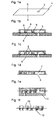
Fig.1a bis f den prinzipiellen Verfahrensablauf für die Herstellung einer einseitigen Negativform, -
Fig.2a bis d den prinzipiellen Verfahrensablauf für die Herstellung einer einseitigen Negativform mit Inselstrukturen, -
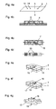
Fig.3a bis f den prinzipiellen Verfahrensablauf für die Herstellung einer zweiseitigen Negativform sowie -
Fig.4a bis g den prinzipiellen Verfahrensablauf für die Herstellung von kombinierten Mikrostrukturen mit Einsetzteilen. - Beispiel 1 gibt den grundlegenden Verfahrensablauf wieder. Es zeigt die Herstellung einer Form mit einseitig zur Folie angeordneten Negativform für eine galvanische oder elektrophoretische Abscheidung zweier Mikrobauteile.
- Folie 1 (
Fig.1a ) wird in einem Spritzgießwerkzeug so angeordnet, dass der Durchbruch 2 an der Formmassenöffnung 3 der ersten Kavität angelagert ist und ein (erster) mikrostrukturierter Formeinsatz 4 mit Mikrostrukturen 8 auf die leitfähige (obere) erste Seite 5 der Folie angeordnet ist (vgl.Fig.1b und c ). Auf der unteren Seite der Folie ist flächig ein weiterer (zweiter) Formeinsatz 6 angebracht. In einem ersten Spritzgießschritt werden die Mikrostrukturen 8 des mikrostrukturierten Formeinsatzes 4 mit einer ersten Spritzgießmasse umspritzt (Fig.1c ); es entsteht auf der ersten Seite der Folie ein die Mikrostrukturen 8 umgebender erster Spritzgussformkörper 7 (vgl.Fig.1d ). Im darauf folgenden zweiten Spritzgussschritt erfolgt nach einer Entfernung des flächig auf der zweiten Seite anliegende zweite Formeinsatz 6 (Fig.1d ) und eines zweiten Formeinsatzes 13 eine Aufbringung eines zweiten Spritzgussformkörpers 10 auf der (unteren) zweiten Seite 9 der Folie (Fig.1e ). Im Anschluss daran erfolgt durch das Entformen des mikrostrukturierten ersten Formeinsatzes 4 sowie des zweiten Formeinsatzes 13 in vorgenannter Weise die Fertigstellung einer einseitig auf die Folie angeordneten Negativformen 19 für die galvanische oder elektrophoretische Abscheidung (Fig.1f ). - Beispiel 2 gibt wie Beispiel 1 einen Verfahrensablauf für die Herstellung einer einseitigen, d.h. nur auf einer Folienseite angeordneten Negativform wieder, jedoch mit der Integration von mindestens einer Inselstruktur. Die Beschreibung von Beispiel 2 konzentriert sich folglich auf die erforderlichen zusätzlichen Schritte oder Änderungen des Herstellungsverfahrens.
- Eine zweite Durchgangsöffnung 11 (
Fig.2a ) in der Folie mündet in eine Kavität 12 in einer Mikrostruktur 8 aus (Fig.2b ) und dient dabei als Einlauf für die zweite Spritzgießmasse in diese Kavität und damit zur Herstellung der Inselstrukturen 18 im zweiten Spritzgussschritt (Fig.2c , vgl.Fig.1e ). Es folgt daraus die Fertigstellung einer einseitig auf der Folie angeordnete Negativform mit Inselstrukturen 18 für die galvanische oder elektrophoretische Abscheidung (Fig.2d ). - Beispiel 3 zeigt die Herstellung einer Form mit beidseitig zur Folie angeordneten Negativformen für eine galvanische oder elektrophoretische Abscheidung von vier Mikrobauteilen wie z.B. von Zahnrädern.
- Ausgehend von einer Folie 1 (
Fig.3a ) mit zwei elektrisch leitfähigen Oberflächen (erste und zweite Seite 5 bzw. 9) und einem Durchbruch 2 wird auf der ersten Seite 5 ein mikrostrukturierter Formeinsatz 4 aufgesetzt (Fig.3b , vgl. auchFig.1b ). In einem ersten Spritzgießschritt (Fig.3c , vgl. auchFig.1c ) wird die Mikrostruktur 8 des Formeinsatzes 4 auf der ersten Seite 5 mit einer Spritzgießmasse umspritzt; es entsteht auf der ersten Seite der Folie ein die Mikrostrukturen umgebender erster Spritzgussformkörper 7. Bis zu diesem Punkt entspricht die Vorgehensweise der in Beispiel 1 beschriebenen. - Danach wird auf die zweite Seite 9 der Folie 1 nach Entfernung des flächigen Formeinsatzes 6 (
Fig.3d ) ein weiterer (zweiter) Formeinsatz 13, jedoch mit Mikrostrukturen 8 aufgesetzt und im darauf folgenden zweiten Spritzgießschritt ein zweiter Spritzgussformkörpers 10 um die Mikrostrukturen aufgetragen (Fig.3e ). Nach Entformen der Formeinsätze entsteht eine beidseitig strukturierte Form (Fig.3f ) mit vier Negativformen 19 für die Galvanoformung oder elektrophoretischen Abscheidung der vier Mikrobauteile. - Beispiel 4 zeigt die Herstellung einer Form mit beidseitig zur Folie angeordneter Negativformen für die galvanische oder elektrophoretische Abscheidung von vier Mikrobauteilen, von denen jeweils zwei zueinander positioniert werden und durch ein Einsetzteil verbunden werden. Das Verfahrensbeispiel eignet sich beispielsweise für die Herstellung von Negativformen für eine Abscheidung von Getriebe- oder Zahnradstufen.
- Ausgehend von einer Folie 1 (
Fig.4a ) mit zwei elektrisch leitfähigen Oberflächen (erste und zweite Seite 5 bzw. 9) und zwei Durchbrüchen 14 wird auf die erste Seite 5 ein mikrostrukturierter Formeinsatz 4, auf der zweiten Seite 9 ein flächig aufliegender Formeinsatz 6 aufgesetzt. Die Mikrostrukturen 8 des ersten Formeinsatzes 5 decken dabei die Durchbrüche 14 und einen Bereich der leitfähigen Folie ab. - In einem ersten Spritzgießschritt werden die Mikrostrukturen 8 auf der ersten Seite mit einer Spritzgießmasse umspritzt; es entsteht auf der ersten Seite 5 der Folie ein die Mikrostrukturen umgebender erster Spritzgussformkörper 7 (
Fig.4b ). - Darauf wird auf die zweite Seite 9 der Folie nach Entfernung des flächigen Formeinsatzes 6 ein weiterer (zweiter) mikrostrukturierter Formeinsatz 13 aufgesetzt, so dass auch hier die Mikrostrukturen die Durchbrüche 14 und einen Bereich der leitfähigen Folie abdecken. Im darauf folgenden zweiten Spritzgießschritt erfolgt eine Aufbringung eines zweiten Spritzgussformkörpers 10 um die Mikrostrukturen 8 des zweiten Formeinsatzes 13 (
Fig.4c ). Nach Entformen der Formeinsätze entsteht eine beidseitig strukturierte Form mit beidseitig offenen Durchbrüchen 14, in die Wellen als Einsetzteile 15 eingesetzt werden (Fig.4d ) und damit die Negativformen für die Galvanoformung oder elektrophoretischen Abscheidung zweier Zahnräder mit Welle komplettiert. -
Fig.4e und f geben perspektivisch einen Ausschnitt um eine der beiden Einsetzteile 15 der inFig.4d dargestellten Negativform wieder, wobeiFig.4e den Verfahrensstand gem.Fig.4d darstellt. - Nach der anschließenden galvanischen oder elektrophoretischen Abscheidung von zwei Zahnrädern 16 und 17 auf der Welle 15 in den Negativformen beidseitig der Folie 1 (
Fig.4f ) erfolgt eine chemische und/oder thermische Entfernung der Spritzgussformkörper 7 und 10 sowie der Folie 1 von der Welle 15 mit den abgeschiedenen Zahnrädern 16 und 17 (Fig.4f ). -
- 1
- Folie
- 2
- Durchbruch
- 3
- Formmassenöffnung
- 4
- erster Formeinsatz
- 5
- erste Seite
- 6
- flächiger Formeinsatz
- 7
- erster Spritzgussformkörper
- 8
- Mikrostruktur
- 9
- zweite Seite
- 10
- zweiter Spritzgussformkörper
- 11
- Durchbruch
- 12
- Kavität
- 13
- zweiter Formeinsatz
- 14
- Durchbruch (für Einsetzteil)
- 15
- Einsetzteil
- 16
- Zahnrad auf erster Seite
- 17
- Zahnrad auf zweiter Seite
- 18
- Inselstruktur
- 19
- Negativform
Claims (10)
Applications Claiming Priority (1)
| Application Number | Priority Date | Filing Date | Title |
|---|---|---|---|
| DE102009010954A DE102009010954A1 (de) | 2009-02-27 | 2009-02-27 | Herstellverfahren für eine Negativform für eine galvanische oder elektrophoretische Abscheidung |
Publications (2)
| Publication Number | Publication Date |
|---|---|
| EP2230059A1 true EP2230059A1 (de) | 2010-09-22 |
| EP2230059B1 EP2230059B1 (de) | 2011-12-07 |
Family
ID=42200309
Family Applications (1)
| Application Number | Title | Priority Date | Filing Date |
|---|---|---|---|
| EP09015663A Not-in-force EP2230059B1 (de) | 2009-02-27 | 2009-12-18 | Herstellverfahren für eine Negativform für eine galvanische oder elektrophoretische Abscheidung |
Country Status (3)
| Country | Link |
|---|---|
| EP (1) | EP2230059B1 (de) |
| AT (1) | ATE536241T1 (de) |
| DE (1) | DE102009010954A1 (de) |
Citations (7)
| Publication number | Priority date | Publication date | Assignee | Title |
|---|---|---|---|---|
| DE19524099A1 (de) * | 1995-07-01 | 1997-01-02 | Karlsruhe Forschzent | Verfahren zur Herstellung von Formeinsätzen |
| DE19652966C1 (de) | 1996-12-19 | 1998-01-22 | Karlsruhe Forschzent | Vorrichtung zur Erzeugung von Mikrostrukturen aus mehrlagigen Kunststoffschichten |
| WO2002057516A2 (en) * | 2001-01-17 | 2002-07-25 | Sandia Corporation | Sacrificial plastic mold with electroplatable base and associated method of manufacture |
| JP2003147570A (ja) * | 2001-11-08 | 2003-05-21 | Sumitomo Electric Ind Ltd | 微細金属部品の製造方法 |
| DE10236812A1 (de) | 2002-08-10 | 2004-02-19 | Forschungszentrum Karlsruhe Gmbh | Verfahren zur Herstellung von Metall- oder Keramik-Mikrobauteilen |
| DE102005012016B3 (de) | 2005-03-16 | 2006-04-27 | Forschungszentrum Karlsruhe Gmbh | Form zur Abscheidung eines Werkstoffs aus einem Elektrolyten, Verfahren zu ihrer Herstellung und ihre Verwendung sowie Verfahren zur Herstellung eines Werkstoffs |
| JP2007070709A (ja) * | 2005-09-09 | 2007-03-22 | Seiko Instruments Inc | 電鋳型、電鋳型の製造方法及び電鋳部品の製造方法 |
Family Cites Families (1)
| Publication number | Priority date | Publication date | Assignee | Title |
|---|---|---|---|---|
| DE10215100A1 (de) * | 2002-04-05 | 2003-10-30 | Bayerische Motoren Werke Ag | Leiterbahn tragende Folie, Spritzgießwerkzeug zum Hinterspritzen von Leiterbahn tragenden Folien sowie Verfahren zur Herstellung eines eine Leiterbahn tragende Folie umfassenden Verbundkörpers |
-
2009
- 2009-02-27 DE DE102009010954A patent/DE102009010954A1/de not_active Ceased
- 2009-12-18 EP EP09015663A patent/EP2230059B1/de not_active Not-in-force
- 2009-12-18 AT AT09015663T patent/ATE536241T1/de active
Patent Citations (7)
| Publication number | Priority date | Publication date | Assignee | Title |
|---|---|---|---|---|
| DE19524099A1 (de) * | 1995-07-01 | 1997-01-02 | Karlsruhe Forschzent | Verfahren zur Herstellung von Formeinsätzen |
| DE19652966C1 (de) | 1996-12-19 | 1998-01-22 | Karlsruhe Forschzent | Vorrichtung zur Erzeugung von Mikrostrukturen aus mehrlagigen Kunststoffschichten |
| WO2002057516A2 (en) * | 2001-01-17 | 2002-07-25 | Sandia Corporation | Sacrificial plastic mold with electroplatable base and associated method of manufacture |
| JP2003147570A (ja) * | 2001-11-08 | 2003-05-21 | Sumitomo Electric Ind Ltd | 微細金属部品の製造方法 |
| DE10236812A1 (de) | 2002-08-10 | 2004-02-19 | Forschungszentrum Karlsruhe Gmbh | Verfahren zur Herstellung von Metall- oder Keramik-Mikrobauteilen |
| DE102005012016B3 (de) | 2005-03-16 | 2006-04-27 | Forschungszentrum Karlsruhe Gmbh | Form zur Abscheidung eines Werkstoffs aus einem Elektrolyten, Verfahren zu ihrer Herstellung und ihre Verwendung sowie Verfahren zur Herstellung eines Werkstoffs |
| JP2007070709A (ja) * | 2005-09-09 | 2007-03-22 | Seiko Instruments Inc | 電鋳型、電鋳型の製造方法及び電鋳部品の製造方法 |
Non-Patent Citations (3)
| Title |
|---|
| PIOTTER V ET AL: "INNOVATIVE MIKROFERTIGUNG: MEHRKOMPONENTEN-MIKROSPRITZGIESSEN", GALVANOTECHNIK, EUGEN G.LEUZE VERLAG, SAULGAU/WURTT, DE, vol. 98, no. 8, 1 August 2007 (2007-08-01), pages 1994 - 1997, XP001507519, ISSN: 0016-4232 * |
| PIOTTER V ET AL: "Multi-component microinjection moulding-trends and developments", THE INTERNATIONAL JOURNAL OF ADVANCED MANUFACTURING TECHNOLOGY, SPRINGER, BERLIN, DE, vol. 47, no. 1-4, 5 March 2009 (2009-03-05), pages 63 - 71, XP019797765, ISSN: 1433-3015 * |
| PROKOP J ET AL: "Manufacturing process for high aspect ratio metallic micro parts made by electroplating on partially conductive templates", MICROSYSTEM TECHNOLOGIES ; MICRO AND NANOSYSTEMS INFORMATION STORAGE AND PROCESSING SYSTEMS, SPRINGER, BERLIN, DE, vol. 14, no. 9-11, 12 February 2008 (2008-02-12), pages 1669 - 1674, XP019632887, ISSN: 1432-1858 * |
Also Published As
| Publication number | Publication date |
|---|---|
| DE102009010954A1 (de) | 2010-09-23 |
| ATE536241T1 (de) | 2011-12-15 |
| EP2230059B1 (de) | 2011-12-07 |
Similar Documents
| Publication | Publication Date | Title |
|---|---|---|
| EP2167304B1 (de) | Computerprogramm, steuereinrichtung und vorrichtung zum aufbringen einer aus mehreren materialien bestehenden produktschicht auf einen formkörper | |
| DE60220022T2 (de) | Verfahren zur herstellung elektrisch leitender kontaktstrukturen | |
| DE4222856C1 (de) | ||
| DE10229952A1 (de) | Metallisches Werkstück sowie Verfahren zur Herstellung eines metallischen Werkstückes | |
| WO2001098052A1 (de) | Verfahren zur herstellung eines hybridteils | |
| EP2652775B1 (de) | Verfahren zur herstellung einer elektronischen baugruppe mit formkörper | |
| EP1815964A2 (de) | Verfahren zum Herstellen eines Verbundteils durch Spritzgiessen oder Spritzprägen oder Hinterpressen von Kunststoffmaterial | |
| DE4432966A1 (de) | Verfahren zum Herstellen eines Bauteils aus thermoplastischem Kunststoff mit wenigstens einem integrierten, elektrisch leitenden Abschnitt sowie nach diesem Verfahren hergestelltes Bauteil | |
| DE4231742A1 (de) | Verfahren zur Herstellung von metallischen, mit Strukturen versehenen plattenförmigen Körpern | |
| EP2230059B1 (de) | Herstellverfahren für eine Negativform für eine galvanische oder elektrophoretische Abscheidung | |
| WO2000076740A1 (de) | Magazin für mikrostrukturierte formteile und verfahren zu dessen herstellung | |
| EP1527214B1 (de) | Verfahren zur herstellung von metall- oder keramik-mikrobauteilen | |
| EP1422194B1 (de) | Verfahren zur Herstellung eines Werkzeugeinsatzes zum Spritzgiessen eines mikrostrukturierten Teils | |
| EP1474065B1 (de) | Verfahren zum herstellen eines zahnersatzes oder kunstzahns | |
| DE102004010703B4 (de) | Bauelement mit WLP-fähiger Verkapselung und Herstellverfahren | |
| DE19709137B4 (de) | Verfahren zur Herstellung und Magazinierung mindestens eines metallischen Mikrobauteils | |
| DE102005012016B3 (de) | Form zur Abscheidung eines Werkstoffs aus einem Elektrolyten, Verfahren zu ihrer Herstellung und ihre Verwendung sowie Verfahren zur Herstellung eines Werkstoffs | |
| DE3440110C1 (de) | Verfahren zur Herstellung mechanisch trennbarer Vielfach-Verbindungen fuer den elektrischen Anschluss mikroelektronischer Bauelemente | |
| DE102009016189B4 (de) | Herstellverfahren für Verbundbauteile mit mindestens zwei Komponenten | |
| EP0887281A2 (de) | Verfahren zur Herstellung von metallischen Mikrobauteilen | |
| DE19638322A1 (de) | Verfahren zur Herstellung von Kunststoffbauteilen mit elektrisch leitfähiger Oberfläche | |
| DE10162450B4 (de) | Tragbarer Datenträger sowie Verfahren und Vorrichtung zur Herstellung | |
| DE10106135A1 (de) | Verfahren und Vorrichtung zur Herstellung von galvanisch abformbaren Negativformen mikrostukturierter Körper,insbesondere Zahnräder | |
| WO2020239463A1 (de) | Verfahren zur herstellung eines formkörpers und bauteil mit elektrischer funktionalität | |
| DE10312693B3 (de) | Verfahren zum Aufbringen von mindestens einer Leiterbahn auf einem Kunststoffbauteil sowie Spritzgusswerkzeug zur Herstellung eines Kunststoffbauteils mit mindestens einer Leiterbahn |
Legal Events
| Date | Code | Title | Description |
|---|---|---|---|
| PUAI | Public reference made under article 153(3) epc to a published international application that has entered the european phase |
Free format text: ORIGINAL CODE: 0009012 |
|
| 17P | Request for examination filed |
Effective date: 20100702 |
|
| AK | Designated contracting states |
Kind code of ref document: A1 Designated state(s): AT BE BG CH CY CZ DE DK EE ES FI FR GB GR HR HU IE IS IT LI LT LU LV MC MK MT NL NO PL PT RO SE SI SK SM TR |
|
| AX | Request for extension of the european patent |
Extension state: AL BA RS |
|
| GRAP | Despatch of communication of intention to grant a patent |
Free format text: ORIGINAL CODE: EPIDOSNIGR1 |
|
| RIC1 | Information provided on ipc code assigned before grant |
Ipc: B29C 33/38 20060101AFI20110311BHEP Ipc: B29C 45/16 20060101ALI20110311BHEP Ipc: C25D 1/10 20060101ALI20110311BHEP |
|
| GRAS | Grant fee paid |
Free format text: ORIGINAL CODE: EPIDOSNIGR3 |
|
| GRAA | (expected) grant |
Free format text: ORIGINAL CODE: 0009210 |
|
| AK | Designated contracting states |
Kind code of ref document: B1 Designated state(s): AT BE BG CH CY CZ DE DK EE ES FI FR GB GR HR HU IE IS IT LI LT LU LV MC MK MT NL NO PL PT RO SE SI SK SM TR |
|
| REG | Reference to a national code |
Ref country code: GB Ref legal event code: FG4D Free format text: NOT ENGLISH |
|
| REG | Reference to a national code |
Ref country code: CH Ref legal event code: NV Representative=s name: ROTTMANN, ZIMMERMANN + PARTNER AG Ref country code: CH Ref legal event code: EP |
|
| REG | Reference to a national code |
Ref country code: IE Ref legal event code: FG4D Free format text: LANGUAGE OF EP DOCUMENT: GERMAN |
|
| REG | Reference to a national code |
Ref country code: NL Ref legal event code: T3 |
|
| REG | Reference to a national code |
Ref country code: DE Ref legal event code: R096 Ref document number: 502009002108 Country of ref document: DE Effective date: 20120209 |
|
| PG25 | Lapsed in a contracting state [announced via postgrant information from national office to epo] |
Ref country code: LT Free format text: LAPSE BECAUSE OF FAILURE TO SUBMIT A TRANSLATION OF THE DESCRIPTION OR TO PAY THE FEE WITHIN THE PRESCRIBED TIME-LIMIT Effective date: 20111207 Ref country code: NO Free format text: LAPSE BECAUSE OF FAILURE TO SUBMIT A TRANSLATION OF THE DESCRIPTION OR TO PAY THE FEE WITHIN THE PRESCRIBED TIME-LIMIT Effective date: 20120307 |
|
| LTIE | Lt: invalidation of european patent or patent extension |
Effective date: 20111207 |
|
| PG25 | Lapsed in a contracting state [announced via postgrant information from national office to epo] |
Ref country code: HR Free format text: LAPSE BECAUSE OF FAILURE TO SUBMIT A TRANSLATION OF THE DESCRIPTION OR TO PAY THE FEE WITHIN THE PRESCRIBED TIME-LIMIT Effective date: 20111207 Ref country code: SI Free format text: LAPSE BECAUSE OF FAILURE TO SUBMIT A TRANSLATION OF THE DESCRIPTION OR TO PAY THE FEE WITHIN THE PRESCRIBED TIME-LIMIT Effective date: 20111207 Ref country code: SE Free format text: LAPSE BECAUSE OF FAILURE TO SUBMIT A TRANSLATION OF THE DESCRIPTION OR TO PAY THE FEE WITHIN THE PRESCRIBED TIME-LIMIT Effective date: 20111207 Ref country code: LV Free format text: LAPSE BECAUSE OF FAILURE TO SUBMIT A TRANSLATION OF THE DESCRIPTION OR TO PAY THE FEE WITHIN THE PRESCRIBED TIME-LIMIT Effective date: 20111207 Ref country code: GR Free format text: LAPSE BECAUSE OF FAILURE TO SUBMIT A TRANSLATION OF THE DESCRIPTION OR TO PAY THE FEE WITHIN THE PRESCRIBED TIME-LIMIT Effective date: 20120308 |
|
| PG25 | Lapsed in a contracting state [announced via postgrant information from national office to epo] |
Ref country code: CY Free format text: LAPSE BECAUSE OF FAILURE TO SUBMIT A TRANSLATION OF THE DESCRIPTION OR TO PAY THE FEE WITHIN THE PRESCRIBED TIME-LIMIT Effective date: 20111207 |
|
| BERE | Be: lapsed |
Owner name: KARLSRUHER INSTITUT FUR TECHNOLOGIE Effective date: 20111231 |
|
| REG | Reference to a national code |
Ref country code: IE Ref legal event code: FD4D |
|
| PG25 | Lapsed in a contracting state [announced via postgrant information from national office to epo] |
Ref country code: IE Free format text: LAPSE BECAUSE OF FAILURE TO SUBMIT A TRANSLATION OF THE DESCRIPTION OR TO PAY THE FEE WITHIN THE PRESCRIBED TIME-LIMIT Effective date: 20111207 Ref country code: CZ Free format text: LAPSE BECAUSE OF FAILURE TO SUBMIT A TRANSLATION OF THE DESCRIPTION OR TO PAY THE FEE WITHIN THE PRESCRIBED TIME-LIMIT Effective date: 20111207 Ref country code: IS Free format text: LAPSE BECAUSE OF FAILURE TO SUBMIT A TRANSLATION OF THE DESCRIPTION OR TO PAY THE FEE WITHIN THE PRESCRIBED TIME-LIMIT Effective date: 20120407 Ref country code: EE Free format text: LAPSE BECAUSE OF FAILURE TO SUBMIT A TRANSLATION OF THE DESCRIPTION OR TO PAY THE FEE WITHIN THE PRESCRIBED TIME-LIMIT Effective date: 20111207 Ref country code: SK Free format text: LAPSE BECAUSE OF FAILURE TO SUBMIT A TRANSLATION OF THE DESCRIPTION OR TO PAY THE FEE WITHIN THE PRESCRIBED TIME-LIMIT Effective date: 20111207 Ref country code: MC Free format text: LAPSE BECAUSE OF NON-PAYMENT OF DUE FEES Effective date: 20111231 Ref country code: BG Free format text: LAPSE BECAUSE OF FAILURE TO SUBMIT A TRANSLATION OF THE DESCRIPTION OR TO PAY THE FEE WITHIN THE PRESCRIBED TIME-LIMIT Effective date: 20120307 |
|
| PG25 | Lapsed in a contracting state [announced via postgrant information from national office to epo] |
Ref country code: RO Free format text: LAPSE BECAUSE OF FAILURE TO SUBMIT A TRANSLATION OF THE DESCRIPTION OR TO PAY THE FEE WITHIN THE PRESCRIBED TIME-LIMIT Effective date: 20111207 Ref country code: PL Free format text: LAPSE BECAUSE OF FAILURE TO SUBMIT A TRANSLATION OF THE DESCRIPTION OR TO PAY THE FEE WITHIN THE PRESCRIBED TIME-LIMIT Effective date: 20111207 Ref country code: PT Free format text: LAPSE BECAUSE OF FAILURE TO SUBMIT A TRANSLATION OF THE DESCRIPTION OR TO PAY THE FEE WITHIN THE PRESCRIBED TIME-LIMIT Effective date: 20120409 |
|
| PLBE | No opposition filed within time limit |
Free format text: ORIGINAL CODE: 0009261 |
|
| STAA | Information on the status of an ep patent application or granted ep patent |
Free format text: STATUS: NO OPPOSITION FILED WITHIN TIME LIMIT |
|
| PG25 | Lapsed in a contracting state [announced via postgrant information from national office to epo] |
Ref country code: BE Free format text: LAPSE BECAUSE OF NON-PAYMENT OF DUE FEES Effective date: 20111231 Ref country code: DK Free format text: LAPSE BECAUSE OF FAILURE TO SUBMIT A TRANSLATION OF THE DESCRIPTION OR TO PAY THE FEE WITHIN THE PRESCRIBED TIME-LIMIT Effective date: 20111207 |
|
| 26N | No opposition filed |
Effective date: 20120910 |
|
| PG25 | Lapsed in a contracting state [announced via postgrant information from national office to epo] |
Ref country code: IT Free format text: LAPSE BECAUSE OF FAILURE TO SUBMIT A TRANSLATION OF THE DESCRIPTION OR TO PAY THE FEE WITHIN THE PRESCRIBED TIME-LIMIT Effective date: 20111207 |
|
| REG | Reference to a national code |
Ref country code: DE Ref legal event code: R097 Ref document number: 502009002108 Country of ref document: DE Effective date: 20120910 |
|
| PG25 | Lapsed in a contracting state [announced via postgrant information from national office to epo] |
Ref country code: MT Free format text: LAPSE BECAUSE OF FAILURE TO SUBMIT A TRANSLATION OF THE DESCRIPTION OR TO PAY THE FEE WITHIN THE PRESCRIBED TIME-LIMIT Effective date: 20111207 Ref country code: MK Free format text: LAPSE BECAUSE OF FAILURE TO SUBMIT A TRANSLATION OF THE DESCRIPTION OR TO PAY THE FEE WITHIN THE PRESCRIBED TIME-LIMIT Effective date: 20111207 |
|
| PG25 | Lapsed in a contracting state [announced via postgrant information from national office to epo] |
Ref country code: SM Free format text: LAPSE BECAUSE OF FAILURE TO SUBMIT A TRANSLATION OF THE DESCRIPTION OR TO PAY THE FEE WITHIN THE PRESCRIBED TIME-LIMIT Effective date: 20111207 |
|
| PG25 | Lapsed in a contracting state [announced via postgrant information from national office to epo] |
Ref country code: LU Free format text: LAPSE BECAUSE OF NON-PAYMENT OF DUE FEES Effective date: 20111218 |
|
| PG25 | Lapsed in a contracting state [announced via postgrant information from national office to epo] |
Ref country code: FI Free format text: LAPSE BECAUSE OF FAILURE TO SUBMIT A TRANSLATION OF THE DESCRIPTION OR TO PAY THE FEE WITHIN THE PRESCRIBED TIME-LIMIT Effective date: 20111207 |
|
| PG25 | Lapsed in a contracting state [announced via postgrant information from national office to epo] |
Ref country code: TR Free format text: LAPSE BECAUSE OF FAILURE TO SUBMIT A TRANSLATION OF THE DESCRIPTION OR TO PAY THE FEE WITHIN THE PRESCRIBED TIME-LIMIT Effective date: 20111207 |
|
| PG25 | Lapsed in a contracting state [announced via postgrant information from national office to epo] |
Ref country code: ES Free format text: LAPSE BECAUSE OF FAILURE TO SUBMIT A TRANSLATION OF THE DESCRIPTION OR TO PAY THE FEE WITHIN THE PRESCRIBED TIME-LIMIT Effective date: 20120318 Ref country code: HU Free format text: LAPSE BECAUSE OF FAILURE TO SUBMIT A TRANSLATION OF THE DESCRIPTION OR TO PAY THE FEE WITHIN THE PRESCRIBED TIME-LIMIT Effective date: 20111207 |
|
| REG | Reference to a national code |
Ref country code: FR Ref legal event code: PLFP Year of fee payment: 7 |
|
| REG | Reference to a national code |
Ref country code: AT Ref legal event code: MM01 Ref document number: 536241 Country of ref document: AT Kind code of ref document: T Effective date: 20141218 |
|
| PG25 | Lapsed in a contracting state [announced via postgrant information from national office to epo] |
Ref country code: AT Free format text: LAPSE BECAUSE OF NON-PAYMENT OF DUE FEES Effective date: 20141218 |
|
| REG | Reference to a national code |
Ref country code: CH Ref legal event code: PCAR Free format text: NEW ADDRESS: GARTENSTRASSE 28 A, 5400 BADEN (CH) |
|
| REG | Reference to a national code |
Ref country code: FR Ref legal event code: PLFP Year of fee payment: 8 |
|
| REG | Reference to a national code |
Ref country code: FR Ref legal event code: PLFP Year of fee payment: 9 |
|
| PGFP | Annual fee paid to national office [announced via postgrant information from national office to epo] |
Ref country code: FR Payment date: 20171219 Year of fee payment: 9 Ref country code: NL Payment date: 20171219 Year of fee payment: 9 |
|
| PGFP | Annual fee paid to national office [announced via postgrant information from national office to epo] |
Ref country code: GB Payment date: 20171221 Year of fee payment: 9 Ref country code: CH Payment date: 20171221 Year of fee payment: 9 |
|
| PGFP | Annual fee paid to national office [announced via postgrant information from national office to epo] |
Ref country code: DE Payment date: 20171219 Year of fee payment: 9 |
|
| REG | Reference to a national code |
Ref country code: DE Ref legal event code: R119 Ref document number: 502009002108 Country of ref document: DE |
|
| REG | Reference to a national code |
Ref country code: CH Ref legal event code: PL |
|
| REG | Reference to a national code |
Ref country code: NL Ref legal event code: MM Effective date: 20190101 |
|
| GBPC | Gb: european patent ceased through non-payment of renewal fee |
Effective date: 20181218 |
|
| PG25 | Lapsed in a contracting state [announced via postgrant information from national office to epo] |
Ref country code: NL Free format text: LAPSE BECAUSE OF NON-PAYMENT OF DUE FEES Effective date: 20190101 |
|
| PG25 | Lapsed in a contracting state [announced via postgrant information from national office to epo] |
Ref country code: FR Free format text: LAPSE BECAUSE OF NON-PAYMENT OF DUE FEES Effective date: 20181231 Ref country code: DE Free format text: LAPSE BECAUSE OF NON-PAYMENT OF DUE FEES Effective date: 20190702 |
|
| PG25 | Lapsed in a contracting state [announced via postgrant information from national office to epo] |
Ref country code: CH Free format text: LAPSE BECAUSE OF NON-PAYMENT OF DUE FEES Effective date: 20181231 Ref country code: LI Free format text: LAPSE BECAUSE OF NON-PAYMENT OF DUE FEES Effective date: 20181231 Ref country code: GB Free format text: LAPSE BECAUSE OF NON-PAYMENT OF DUE FEES Effective date: 20181218 |