EP2229829B1 - Helmet having a guiding mechanism for a compatible visor - Google Patents
Helmet having a guiding mechanism for a compatible visor Download PDFInfo
- Publication number
- EP2229829B1 EP2229829B1 EP10002622A EP10002622A EP2229829B1 EP 2229829 B1 EP2229829 B1 EP 2229829B1 EP 10002622 A EP10002622 A EP 10002622A EP 10002622 A EP10002622 A EP 10002622A EP 2229829 B1 EP2229829 B1 EP 2229829B1
- Authority
- EP
- European Patent Office
- Prior art keywords
- visor
- pivot
- shell
- helmet
- link
- Prior art date
- Legal status (The legal status is an assumption and is not a legal conclusion. Google has not performed a legal analysis and makes no representation as to the accuracy of the status listed.)
- Not-in-force
Links
- 230000007246 mechanism Effects 0.000 title claims description 60
- 210000003128 head Anatomy 0.000 description 5
- 230000000694 effects Effects 0.000 description 3
- 230000000750 progressive effect Effects 0.000 description 3
- 230000006378 damage Effects 0.000 description 2
- 210000001061 forehead Anatomy 0.000 description 2
- 230000001681 protective effect Effects 0.000 description 2
- 230000000717 retained effect Effects 0.000 description 2
- 206010019196 Head injury Diseases 0.000 description 1
- YXOLAZRVSSWPPT-UHFFFAOYSA-N Morin Chemical compound OC1=CC(O)=CC=C1C1=C(O)C(=O)C2=C(O)C=C(O)C=C2O1 YXOLAZRVSSWPPT-UHFFFAOYSA-N 0.000 description 1
- 208000027418 Wounds and injury Diseases 0.000 description 1
- 238000013459 approach Methods 0.000 description 1
- 239000002537 cosmetic Substances 0.000 description 1
- 239000006260 foam Substances 0.000 description 1
- 230000008014 freezing Effects 0.000 description 1
- 238000007710 freezing Methods 0.000 description 1
- 239000004619 high density foam Substances 0.000 description 1
- 230000008595 infiltration Effects 0.000 description 1
- 238000001764 infiltration Methods 0.000 description 1
- 208000014674 injury Diseases 0.000 description 1
- 239000000463 material Substances 0.000 description 1
- UXOUKMQIEVGVLY-UHFFFAOYSA-N morin Natural products OC1=CC(O)=CC(C2=C(C(=O)C3=C(O)C=C(O)C=C3O2)O)=C1 UXOUKMQIEVGVLY-UHFFFAOYSA-N 0.000 description 1
- 235000007708 morin Nutrition 0.000 description 1
- 239000004033 plastic Substances 0.000 description 1
- 230000002441 reversible effect Effects 0.000 description 1
- 238000007789 sealing Methods 0.000 description 1
- 210000003813 thumb Anatomy 0.000 description 1
Images



Classifications
-
- G—PHYSICS
- G02—OPTICS
- G02B—OPTICAL ELEMENTS, SYSTEMS OR APPARATUS
- G02B27/00—Optical systems or apparatus not provided for by any of the groups G02B1/00 - G02B26/00, G02B30/00
- G02B27/01—Head-up displays
- G02B27/017—Head mounted
- G02B27/0176—Head mounted characterised by mechanical features
-
- A—HUMAN NECESSITIES
- A42—HEADWEAR
- A42B—HATS; HEAD COVERINGS
- A42B3/00—Helmets; Helmet covers ; Other protective head coverings
- A42B3/04—Parts, details or accessories of helmets
- A42B3/18—Face protection devices
- A42B3/185—Securing goggles or spectacles on helmet shells
-
- A—HUMAN NECESSITIES
- A42—HEADWEAR
- A42B—HATS; HEAD COVERINGS
- A42B3/00—Helmets; Helmet covers ; Other protective head coverings
- A42B3/04—Parts, details or accessories of helmets
- A42B3/18—Face protection devices
- A42B3/22—Visors
- A42B3/221—Attaching visors to helmet shells, e.g. on motorcycle helmets
- A42B3/222—Attaching visors to helmet shells, e.g. on motorcycle helmets in an articulated manner, e.g. hinge devices
-
- G—PHYSICS
- G02—OPTICS
- G02B—OPTICAL ELEMENTS, SYSTEMS OR APPARATUS
- G02B27/00—Optical systems or apparatus not provided for by any of the groups G02B1/00 - G02B26/00, G02B30/00
- G02B27/01—Head-up displays
- G02B27/0149—Head-up displays characterised by mechanical features
- G02B2027/0154—Head-up displays characterised by mechanical features with movable elements
- G02B2027/0156—Head-up displays characterised by mechanical features with movable elements with optionally usable elements
Definitions
- the present invention generally relates to the field of helmets. More specifically, the invention relates to a helmet having a guiding mechanism for a compatible visor for use in sports, such as skiing or other activities where it is advantageous to position the visor close to the face of a wearer.
- the skier gets to the bottom of the slopes and waits in line for the chairlifts, he often takes his goggles off, letting them rest in equilibrium on a front portion of the helmet, retained by the goggles' elastic band.
- the goggles are not perfectly positioned, they will often either flip up and end up retained by a retaining strap at the back of the helmet, or flip down, striking the eyes of the wearer completely caught off guard.
- US patent no. 4,287,615 to Morin discloses a ski helmet having an integrated withdrawable visor.
- the visor is moveable between a deployed position within a wearer's field of view for use of the visor and a retracted position behind a helmet shell.
- As the visor is deployed its edges follow a guiding surface against which it is biased by a spring.
- the guiding surface is made so that the visor moves towards a face of the wearer, sealing his eyes against wind infiltration.
- the movement required to move the visor is not natural as the wearer is required to move a lever, located at the base of the helmet, towards the front to retract the visor and towards the back to deploy the visor.
- the wearer intends to retract the visor with a more natural movement, such as by grabbing a bottom portion of the visor with his thumb and pushing up the visor, the visor will likely not retract properly as the wearer, wearing thick gloves or mittens, will often lift the visor too much forward, off its guiding surfaces, resulting in rubbing the visor against the helmet shell and preventing it from retracting properly in its pocket, located between the helmet shell and a helmet liner.
- US patent 6,804,829 to Crye et al. describes a combat helmet.
- the combat helmet among others, comprises a retractable visor.
- the visor is pivotally attached to the helmet and is moveable in an arcuate path between a deployed position within the field of view of the wearer and a retracted position behind a helmet shell.
- the visor moves in a simple arcuate path, the visor engages the face of the wearer with a downward pressure, thereby providing an unpleasant feeling.
- this downward motion of the shield does not efficiently seal the shield against the face of the wearer.
- EP 0668029 Soc d Negooce et d'Achats de Mav et al. discloses a helmet for industrial use with a visor articulated on two lateral plates which slide in two opposite slides on the lateral walls of the helmet. The lower end of each slide is level with the lower edge of the helmet. A stud on each plate engages in a window in the slide and locks the plate automatically in its position of use. The visor is removed by sliding the plates down manually. The visor is articulated on each plate by two rods, the upper rod being joined to the plate by a spring. In the retracted position, the visor is proximate the frontal portion of the helmet and outside the field of view of the wearer. The visor is moved downwardly and backwardly from the retracted position to a deployed position in which the visor is substantially below the lower edge of the helmet.
- US 5752280 Hill discloses an eyeshield removably attached to a headband.
- the eye shield manually rotates from a normal viewing position to an out of viewing position above the forehead of a wearer by means of two pivot arms attached to a bistable tensioning pivotal mechanism.
- This mechanism applies tension to keep the eyeshield held firmly in place in the normal viewing position; and when the eyeshield is manually lifted toward the out of viewing position, tension is applied in the reverse direction to keep the eyeshield held in the out of viewing position.
- a helmet comprising: a shell adapted to contact a wearer's head, said shell having a frontal portion and a rear portion, said frontal portion having a frontal lower edge; a visor, said visor having a lower portion; and two guiding mechanisms adapted to receive said visor, each one of said two guiding mechanisms being located on a different side of said shell, said guiding mechanisms being operative to guide at least said lower portion of said visor along a confined path extending from a retracted position where said visor is substantially proximate said frontal portion of said shell and substantially outside a field of view of the wearer to a deployed position where said visor is substantially below said frontal lower edge and within the field of view of the wearer, said visor being equipped with a face seal, said face seal being located in said lower portion of said visor, said guiding mechanisms being further operative to guide said lower portion of said visor substantially in the direction of said rear portion of said shell when said visor is guided from said
- confined will be understood to mean that something, here the visor, is restricted in its movement. More precisely, the term “confined” is used to indicate that the visor is restricted in its movement to follow a specific path determined by the geometry of guiding mechanisms of the helmet.
- Each one of the two guiding mechanisms may further comprise a first link that pivots on a first pivot.
- Each one of the first link is adapted to pivotably connect to the visor. The first link is in a first position when the visor is in the retracted position and moves to a second position when the visor is in the deployed position.
- Each one of the two guiding mechanisms may be connected to the visor through a visor adaptor that is adapted to receive the visor.
- the helmet may comprise a guiding slot adapted to engage and to guide an upper portion of the visor.
- the guiding slot may either be located on a centerline of the shell or alternatively, there may be two guiding slots, one on each side of the shell.
- Each one of the two guiding mechanisms may further comprise a second link that pivots on a second pivot.
- the first link and the second link are adapted to pivotably connect to the visor respectively at a third pivot and at a fourth pivot.
- the third pivot is located substantially below the first pivot and the fourth pivot is located substantially above the second pivot when the visor is in the deployed position.
- the third pivot may be located substantially above the first pivot and the fourth pivot may be located substantially above the second pivot when the visor is in the retracted position.
- At least one of the two guiding mechanisms may further comprise a biasing means adapted to bias the visor towards the deployed position.
- the biasing means is operative to bias the first link towards the second position when the visor is in the deployed position.
- the biasing means may also be operative to bias the first link towards the first position when the visor is in the retracted position.
- the helmet of any of the variants as previously described may be made so that its shell comprises a pocket adapted to receive the visor when the first link is in the first position and the visor is in the retracted position.
- This pocket may be located between an outer shell and a liner of the shell.
- the helmet of any of the previously described variants may be of an open-face type.
- FIG. 1 depicts a helmet 10.
- the helmet 10 comprises a shell 12, two guiding mechanisms 14 (one on each side of the helmet 10) and a visor 16.
- the shell 12 is operative to contact a wearer's head and to protect the head by absorbing the energy from an unfortunate impact.
- the shell 12 typically comprises an outer shell 18, on the exterior of the shell 12 and which is mostly used to distribute the impact over a larger area while providing a nice exterior cosmetic appearance, and an impact energy absorbing liner 20, inside the outer shell 18.
- the liner 20 fits the head of the wearer and acts as a damper by absorbing most of the impact energy by deformation so that as little energy as possible is transferred to the head.
- high-density foam is used as the liner material.
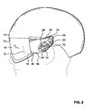
- Each guiding mechanism 14 is located on a different side of the shell 12 and both are adapted to receive and to guide the visor 16 along a confined path 22, best shown in Figure 2 and now concurrently referred to.
- a guiding mechanism cover has been removed to get a detailed view of the inside of the guiding mechanism 14.
- the left guiding mechanism 14 is represented. It will be understood that the guiding mechanism on the right side of the shell 12 is a mirror image of the one on the left side.
- Each guiding mechanism 14 comprises a first link 24 and a second link 26.
- the first and second links 24, 26 are pivotably connected to the visor 16 respectively through a third pivot 32 and a fourth pivot 34.
- first link 24 is pivotably connected to a first connecting portion 36 of the visor 16 while the second link 26 is connected to a second connecting portion 38 of the visor 16.
- first connecting portion 36 is located lower than the second connecting portion 38 when the visor 16 is in its deployed position.
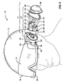
- Each guiding mechanism 14 comprises a housing 40 having a base 42 and a cover 44.
- the housing 40 is attached to the shell 12.
- the housing 40 could be integrated in the shell 12 and then the first and second links 24, 26 may be attached directly to the shell 12.
- the visor 16 is provided with a face seal 46.
- the face seal 46 is similar to the face seals of conventional goggles, except that it does not completely surround the visor 16 as in conventional goggles.
- the face seal 46 is typically made of a soft, resilient plastic and may comprise soft foam to comfortably contact the face of the wearer. As with conventional goggles, the face seal 46 may incorporate vents to provide air circulation and to prevent the visor 16 from fogging.
- the visor 16 may also be provided with a finger-catching tab 48 so that the wearer may move the visor 16 from its retracted position to its deployed position and vice-versa.
- the tab 48 may be located in a variety of positions, it may be more convenient to locate the tab 48 on the face seal 46.
- the tab 48 could be designed as a recess in the face seal 46.
- the visor 16 is mounted to each guiding mechanisms 14 through its helmet mounting interfaces 49.
- the helmet mounting interfaces 49 may either be integrated with a lens 51 or be two separate parts attached to the lens 51.
- the visor 16 When the user moves the visor 16 from its retracted position to its deployed position and vice-versa, the visor 16 follows the confined path 22. In fact, every single virtual point on the visor 16 actually follows its own single confined path 22.
- the confined path 22 depicted in Figures 2 and 4 is the confined path followed by one virtual reference point located in a lower portion 50 of the visor 16, here more specifically on the face seal 46.
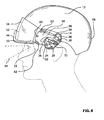
- the confined path 22 depicts the movement of this virtual reference point that extends from the retracted position of the visor 16, as depicted in Figure 4 , to the deployed position of the visor 16, as depicted in Figure 2 .
- the visor 16 In the retracted position, the visor 16 is substantially proximate the frontal portion 52 of the shell 12 and substantially outside a field of view 54 of the wearer. In the deployed position, the visor 16 is substantially below a frontal lower edge 53 and within the field of view 54 of the wearer. As can be seen from the shape of the confined path 22, the guiding mechanisms 14 guide at least the lower portion 50 of the visor 16 substantially towards a rear portion 56 of the shell 12 when the compatible visor 16 is in the deployed position. Indeed, the confined path 22 turns towards the rear portion 56 in its lower part.
- This rearward motion of the lower portion 50 of the visor 16 advantageously allows the lower portion 50, and more specifically the face seal 46, to contact the face of the wearer and seal against it, thereby preventing wind from seeping in between the visor 16 and the face of the wearer.
- the rearward motion of the lower portion 50 of the visor 16 although not purely rearward, is still predominantly directed towards the rear portion 56 of the shell 12. This is in contrast with visor motion of the prior art where the visors often pivot around a single axis and have a predominantly downward direction of motion when they reach within the field of view of the wearer.
- the confined path 22 depicted in Figures 2 and 4 is the same whether the visor 16 is moving from its retracted position to its deployed position or from its deployed position to its retracted position. However, this does not necessarily need to be the case. Indeed, the visor 16 could follow a slightly different trajectory whether it is retracting or deploying, as long as the visor 16 does not substantially come into contact with the outer shell 18 or the liner 20, which could damage the visor 16.
- the important objective is that the guiding mechanism 14 does not allow any substantial movement of the visor 16 outside of the confined path 22, which could prevent the visor 16 to properly move to its retracted position, either over the outer shell 18, or between the outer shell 18 and the liner 20.
- Figure 2 depict the visor 16 directly mounted to the guiding mechanisms 14
- Figures 3 to 4 depict the visor 16 connected to each guiding mechanism 14 through an optional visor adaptor 58.
- the visor 16 may be directly connected to the guiding mechanisms 14 it is convenient to use the visor adaptors 58 to receive the visor 16 since their visor mounting interface 60 is more accessible than are the first and second links 24, 26 located inside the housing 40.
- Using the visor adaptors 58 to connect the visor 16 to the guiding mechanisms 14 allows for a quick replacement of the visor 16, for example if the wearer wants to replace his visor for one better adapted to the ambient type of lighting, or if the visor 16 becomes scratched.
- the visor adaptors 58 comprise the first and the second connecting portions 36, 38 similarly to the visor 16 of Figure 2 .
- the first link 24 is connected to the first connecting portion 36 of the visor adaptor 58 at the third pivot 32 and the second link 26 is connected to the second connecting portion 38 of the visor adaptor 58 at the fourth pivot 34, again similarly to the connections of the first and the second links 24, 26 to the visor 16 of Figure 2 .
- the first connecting portion 36 is lower than the second connecting portion.
- the visor mounting interface 60 may be designed in many different ways such that the visor 16 is quickly and easily detachable from the visor adaptors 58, even by an un-experienced wearer.
- the visor mounting interfaces 60 may comprise mounting holes 62 on the visor adaptors 58. These mounting holes 62 are designed to match with corresponding visor holes 64 in the visor 16 and both the mounting holes 62 and visor holes 64 are engaged by corresponding bosses 66 in a decorative cover 68.
- a screw 70 may be used to hold the visor 16 to the decorative covers 68 through the visor adaptors 58, precisely locating the visor 16.
- the screw 70 may be of a type that may readily be removed with a dime or a screwdriver. It will be apparent to a person skilled in the art that many other types of quick connections may be used.
- the guiding mechanism 14 may further comprise a biasing means 72 to bias the lower portion 50 of the visor 16, and more specifically the face seal 46, towards the rear portion 54 of the shell 12 when the visor 16 is in its deployed position.
- the biasing means 72 provides a force that pulls the visor 16 against the face of the wearer, similarly to the way an elastic band of conventional goggles would do. This force, pulling the visor 16 towards the rear portion 56 of the shell 12, helps seal the face seal 46 against the face of the wearer, preventing wind and snow from seeping in.
- the biasing means 72 may help the visor 16 stay in its deployed position within the field of view 54 of the wearer.
- biasing means 72 may also prevent undesired relative motion between the visor 16 and the face of the wearer.
- the biasing means 72 is depicted as an elastic band in Figures 2 to 4 , it will be apparent to a person skilled in the art that many types of biasing mans could be used.
- the biasing means 72 may be, but is not limited to, any type of spring (coil spring, leaf spring, air spring, etc), an elastic band, etc.
- the biasing means 72 is shown connected to the first link 24, it could also be functionally connected to the visor 16 or the visor adaptor 58.
- the biasing means 72 may also bias the visor 16 towards a lower or an upper portion of the confined path 22.
- the biasing means 72 attaches between the first link 24 and the shell 12 through a mounting post which is part of the housing 40.
- the biasing means 72 is routed below the first pivot 28 when the visor 16 is in its deployed position ( Figure 2 ) and is routed above the first pivot 28 when the visor 16 is in the retracted position ( Figure 4 ).
- the biasing means 72 is operative to bias the visor 16 towards an upper portion of the confined path 22, or towards the fully retracted position of the visor 16, as long as the biasing means 72 is routed above the first pivot 28.
- the biasing means 72 is also operative to bias the visor 16 towards a lower portion of the confined path 22, or towards the fully deployed position of the visor 16, when the biasing means 72 is routed below the first pivot 28.
- the wearer In use, the wearer would move the visor 16 from its initial position, for example the retracted position, to the deployed position by pulling on the tab 48. Once the biasing means 72 passes below the first pivot 28, it starts pulling the visor 16 towards the lower part of the confined path 22 so that at least the lower portion of the visor 16 contacts the face of the wearer. Once the biasing means 72 passed from above the first pivot 28 to below the first pivot 28, the wearer does not have to pull on the tab 48 and the visor is deployed automatically by the biasing means 72 for the remainder of the confined path 22.
- the biasing means 72 may be used to only bias the visor 16 towards the lower portion of the confined path 22 (deployed biased), towards the upper portion of the confined path 22 (retracted biased) or, as explained and shown in Figures 2 to 4 , towards both the upper and the lower portions of the confined path 22, depending where the visor 16 is located in the confined path 22.
- Figures 1 and 5 are now referred to.
- the visor 16 may retract over the outer shell 18 as shown in Figures 2 to 4 and much in the fashion of a jet fighter pilot helmet, the visor 16 may alternatively retract inside a pocket 76, either located between the outer shell 18 and the liner 20 or between the outer shell 18 and a visor cover 78, which is the option depicted here.
- the outer shell 18 may be provided with one or more openings 80 directly over the retracted visor 16, at the bottom of the pocket 76, or a combination of both.
- air infiltrating inside the pocket 76 from its front opening 82 may also be channeled over the visor 16 to prevent fogging.
- the helmet 10 may be equipped with different other convenient mechanisms such as, for example, a catching mechanism that may be used to lock the visor 16 in one of its biased positions, for example, in its retracted position.
- This catching mechanism may be positioned anywhere it may contact a moveable part, such as the visor 16, the first link 24 or the second link 26, so as to ultimately retain the visor in a given position with respect to the shell 12.
- the catching mechanism may be located within the housing 40 and catch the first link 24, or at the bottom of the pocket 76 and catch the visor 16 in its retracted position.
- the catching mechanism may be of the type that is released by a release actuator, like a release button for example, or of the type that releases when a pushing impulse is provided against the catching mechanism.
- release actuator activated catching mechanism that is operative to catch the visor 16 and lock the visor 16 in its retracted position with a visor 16 that is solely biased by the biasing means 72 towards the deployed position.
- a progressive locating mechanism (mechanisms having multiple pre-set positions) may be used to locate the visor 16.
- Such progressive locating mechanisms may take many forms.
- FIGs 6 and 7 depict another embodiment of helmet.
- This variant is somewhat similar to the previous embodiment in that it comprises the two guiding mechanisms 14, each one located on a different side of the shell 12, which are adapted to receive the visor 16.
- the guiding mechanisms 14 are operative to guide the visor 16 along the confined path 22 which extends from the retracted position, where the visor 16 is substantially proximate the frontal portion 52 of the shell 12 and substantially outside the field of view 54 of the wearer to the deployed position where the visor 16 is mostly below the frontal lower edge 53 (best shown in Figure 2 ) and within the field of view 54 (best shown in Figure 4 ) of the wearer.
- the guiding mechanisms 14 guide at least the lower portion 50 of the visor 16 substantially towards the rear portion 56 (best shown in Figure 4 ) of the shell 12. This ensures an adequate seal of the visor 16, and more particularly of the face seal 46, against the wearer's face.
- Each guiding mechanisms 14 has its first links 24 pivotably connected to the visor 16, either directly or through the visor adaptor 58. Again, each first links 24 pivot on the first pivot 28. In the present embodiment, however, the guiding mechanisms 14 do without the second links, which are replaced by a guiding slot 84 that guides an upper portion 86 of the visor 16. The upper portion 86 of the visor 16 is free to pivot in the guiding slot 84 so that when the visor 16 is moved from its retracted position to its deployed position (or vice versa), the first links 24 position the lower portion 50 of the visor 16 while the upper portion 86 of the visor 16 slides, and slightly pivots, within the guiding slot 84.
- the guiding slot 84 may be located on a longitudinal centerline of the shell 12, either within the shell 12, on the surface of the shell 12, or on an interior of the visor cover 78 (not shown) inside the pocket 76 (not shown). Alternatively, two guiding slots 84 may be used, one on each side of the shell 12 so as to guide each side of the upper portion 86 of the visor 16.
- the guiding slot 84 may adopt different cross-sections, such as an inverted "T" shape that is operative to engage a guiding interface 88 such as a guiding boss, best shown in Figure 8 , now concurrently referred to, located in the upper portion 86 of the visor 16.
- a guiding interface 88 such as a guiding boss
- FIG 9 An example of the "T" shaped guiding slot 84 is depicted in Figure 9 , now concurrently referred to.
- the guiding interface 88 adopts a cylindrical shape that allows it to simultaneously slide and pivot within the guiding slot 84. This allows the guiding mechanisms 14 to guide the lower portion 50 of the visor 16 towards the rear portion 56 of the shell 12.
- the guiding slot 84 and guiding interface 88 could adopt different alternative operative designs.
- the visor 16 could be equipped with the guiding slot 84 (albeit shorter than that currently shown on the shell 12) which would engage the guiding interface 88 (which would be extending to look more like a protrusion) extending along the front portion of the shell 12.
- Such alternative designs that perform the same function are intended to be covered by the present description.
- the biasing means 72 may be used to bias the visor 16, directly or through one or both first links 24, from the deployed position to the retracted position, from the retracted position to the deployed position, or towards both as described previously.
- the guiding mechanism 14 is designed so that the biasing means 72 will bias the visor 16 towards the retracted position when the visor is in the upper portion of the confined path 22 and towards the deployed position when the visor 16 is the lower portion of the confined path 22.
- actuating the visor 16 could be used to activate the visor 16 from the deployed position to the retracted position and vice-versa.
- different types of mechanical systems using known concepts such as cams, lever, knobs, gears, etc.
- pneumatic or electric actuators, electric motors could be used as well in a system that activates the visor 16.
- Most of these alternative actuating means could also be used to adjust the force with which the visor 16 seals against the face of the wearer. All of these actuating means could be used either by themselves or in combination with the biasing means 72.
Landscapes
- Physics & Mathematics (AREA)
- General Physics & Mathematics (AREA)
- Optics & Photonics (AREA)
- Helmets And Other Head Coverings (AREA)
Description
- The present invention generally relates to the field of helmets. More specifically, the invention relates to a helmet having a guiding mechanism for a compatible visor for use in sports, such as skiing or other activities where it is advantageous to position the visor close to the face of a wearer.
- The use of protective gear in activities, such as some sports, containing some risk is always recommended. Although occurrence of a serious accident may sometimes be remote, people are becoming more aware that if such accident happens, head injuries are among the most serious injuries a person may suffer. Fortunately, with improved designs, reduced weight and increased comfort, protective helmets have gained tremendous popularity in recent years, especially in sports such as biking and downhill skiing.
- Because of wind and cold, skiers very often wear goggles over their helmet. Unfortunately, this is not the most convenient design as wind may infiltrate in between the helmet and the goggles, freezing a wearer's forehead. This is especially true if there is a less than perfect match between the helmet and the goggles.
- Furthermore, when the skier gets to the bottom of the slopes and waits in line for the chairlifts, he often takes his goggles off, letting them rest in equilibrium on a front portion of the helmet, retained by the goggles' elastic band. However, if the goggles are not perfectly positioned, they will often either flip up and end up retained by a retaining strap at the back of the helmet, or flip down, striking the eyes of the wearer completely caught off guard.
- To mitigate these inconveniences, interesting solutions have been proposed.
US patent no. 4,287,615 to Morin discloses a ski helmet having an integrated withdrawable visor. The visor is moveable between a deployed position within a wearer's field of view for use of the visor and a retracted position behind a helmet shell. As the visor is deployed, its edges follow a guiding surface against which it is biased by a spring. As the visor reaches its fully deployed position, the guiding surface is made so that the visor moves towards a face of the wearer, sealing his eyes against wind infiltration. However, the movement required to move the visor is not natural as the wearer is required to move a lever, located at the base of the helmet, towards the front to retract the visor and towards the back to deploy the visor. Furthermore, if the wearer intends to retract the visor with a more natural movement, such as by grabbing a bottom portion of the visor with his thumb and pushing up the visor, the visor will likely not retract properly as the wearer, wearing thick gloves or mittens, will often lift the visor too much forward, off its guiding surfaces, resulting in rubbing the visor against the helmet shell and preventing it from retracting properly in its pocket, located between the helmet shell and a helmet liner. -
US patent 6,804,829 to Crye et al. describes a combat helmet. The combat helmet, among others, comprises a retractable visor. The visor is pivotally attached to the helmet and is moveable in an arcuate path between a deployed position within the field of view of the wearer and a retracted position behind a helmet shell. However, because the visor moves in a simple arcuate path, the visor engages the face of the wearer with a downward pressure, thereby providing an unpleasant feeling. Moreover, this downward motion of the shield does not efficiently seal the shield against the face of the wearer. - There is therefore a need for an improved helmet that integrates a visor but that does not have the shortcomings of the prior art.
-
EP 0668029 Soc d Negooce et d'Achats de Mav et al. discloses a helmet for industrial use with a visor articulated on two lateral plates which slide in two opposite slides on the lateral walls of the helmet. The lower end of each slide is level with the lower edge of the helmet. A stud on each plate engages in a window in the slide and locks the plate automatically in its position of use. The visor is removed by sliding the plates down manually. The visor is articulated on each plate by two rods, the upper rod being joined to the plate by a spring. In the retracted position, the visor is proximate the frontal portion of the helmet and outside the field of view of the wearer. The visor is moved downwardly and backwardly from the retracted position to a deployed position in which the visor is substantially below the lower edge of the helmet. -
US 5752280 Hill discloses an eyeshield removably attached to a headband. The eye shield manually rotates from a normal viewing position to an out of viewing position above the forehead of a wearer by means of two pivot arms attached to a bistable tensioning pivotal mechanism. This mechanism applies tension to keep the eyeshield held firmly in place in the normal viewing position; and when the eyeshield is manually lifted toward the out of viewing position, tension is applied in the reverse direction to keep the eyeshield held in the out of viewing position. - In accordance with the present disclosure, there is provided a helmet comprising: a shell adapted to contact a wearer's head, said shell having a frontal portion and a rear portion, said frontal portion having a frontal lower edge; a visor, said visor having a lower portion; and two guiding mechanisms adapted to receive said visor, each one of said two guiding mechanisms being located on a different side of said shell, said guiding mechanisms being operative to guide at least said lower portion of said visor along a confined path extending from a retracted position where said visor is substantially proximate said frontal portion of said shell and substantially outside a field of view of the wearer to a deployed position where said visor is substantially below said frontal lower edge and within the field of view of the wearer, said visor being equipped with a face seal, said face seal being located in said lower portion of said visor, said guiding mechanisms being further operative to guide said lower portion of said visor substantially in the direction of said rear portion of said shell when said visor is guided from said retracted position to said deployed position, so that in use said face seal is operative to contact a face of the wearer.
- The term "confined" will be understood to mean that something, here the visor, is restricted in its movement. More precisely, the term "confined" is used to indicate that the visor is restricted in its movement to follow a specific path determined by the geometry of guiding mechanisms of the helmet.
- Each one of the two guiding mechanisms may further comprise a first link that pivots on a first pivot. Each one of the first link is adapted to pivotably connect to the visor. The first link is in a first position when the visor is in the retracted position and moves to a second position when the visor is in the deployed position.
- Each one of the two guiding mechanisms may be connected to the visor through a visor adaptor that is adapted to receive the visor.
- Optionally, the helmet may comprise a guiding slot adapted to engage and to guide an upper portion of the visor. The guiding slot may either be located on a centerline of the shell or alternatively, there may be two guiding slots, one on each side of the shell.
- Each one of the two guiding mechanisms may further comprise a second link that pivots on a second pivot. The first link and the second link are adapted to pivotably connect to the visor respectively at a third pivot and at a fourth pivot.
- Optionally, the third pivot is located substantially below the first pivot and the fourth pivot is located substantially above the second pivot when the visor is in the deployed position. Optionally, the third pivot may be located substantially above the first pivot and the fourth pivot may be located substantially above the second pivot when the visor is in the retracted position.
- Optionally, at least one of the two guiding mechanisms may further comprise a biasing means adapted to bias the visor towards the deployed position. The biasing means is operative to bias the first link towards the second position when the visor is in the deployed position. Optionally, the biasing means may also be operative to bias the first link towards the first position when the visor is in the retracted position.
- Optionally, the helmet of any of the variants as previously described may be made so that its shell comprises a pocket adapted to receive the visor when the first link is in the first position and the visor is in the retracted position. This pocket may be located between an outer shell and a liner of the shell.
- The helmet of any of the previously described variants may be of an open-face type.
- These and other features will become more apparent from the following description in which reference is made to the appended drawings wherein:
-
Figure 1 is an axonometric view of a helmet with a visor in a deployed position; -
Figure 2 is a side view of the helmet ofFigure 1 , without a visor cover, showing both the detail of a guiding mechanism and a confined path followed by a virtual reference point located at a bottom portion of the visor, which is shown in its deployed position; -
Figure 3 is an exploded axonometric view of the helmet ofFigure 1 without the visor cover and having the visor in the retracted position; -
Figure 4 is side view of the helmet ofFigure 1 , without the visor cover, having its visor in its retracted position; -
Figure 5 is a longitudinal cross-sectional side view of the helmet ofFigure 1 ; -
Figure 6 is an axonometric view of another embodiment of helmet with a visor in a retracted position; -
Figure 7 is an axonometric view of the helmet ofFigure 6 having the visor in the deployed position; -
Figure 8 is an axonometric view of the visor featured inFigure 6 ; -
Figure 9 is an axonometric view of a shell of the helmet featured inFigure 6 . -
Figure 1 depicts ahelmet 10. Thehelmet 10 comprises ashell 12, two guiding mechanisms 14 (one on each side of the helmet 10) and avisor 16. Theshell 12 is operative to contact a wearer's head and to protect the head by absorbing the energy from an unfortunate impact. Theshell 12 typically comprises anouter shell 18, on the exterior of theshell 12 and which is mostly used to distribute the impact over a larger area while providing a nice exterior cosmetic appearance, and an impactenergy absorbing liner 20, inside theouter shell 18. Theliner 20 fits the head of the wearer and acts as a damper by absorbing most of the impact energy by deformation so that as little energy as possible is transferred to the head. Typically, high-density foam is used as the liner material. - Each guiding
mechanism 14 is located on a different side of theshell 12 and both are adapted to receive and to guide thevisor 16 along a confinedpath 22, best shown inFigure 2 and now concurrently referred to. OnFigure 2 , a guiding mechanism cover has been removed to get a detailed view of the inside of theguiding mechanism 14. In this Figure, theleft guiding mechanism 14 is represented. It will be understood that the guiding mechanism on the right side of theshell 12 is a mirror image of the one on the left side. Each guidingmechanism 14 comprises afirst link 24 and asecond link 26. The first andsecond links second pivot second links visor 16 respectively through athird pivot 32 and afourth pivot 34. More specifically, thefirst link 24 is pivotably connected to a first connectingportion 36 of thevisor 16 while thesecond link 26 is connected to a second connectingportion 38 of thevisor 16. In the present design, the first connectingportion 36 is located lower than the second connectingportion 38 when thevisor 16 is in its deployed position. -
Figure 3 , where details of theguiding mechanism 14 are shown in an exploded view, is now referred to. Each guidingmechanism 14 comprises ahousing 40 having a base 42 and acover 44. Thehousing 40 is attached to theshell 12. Optionally, thehousing 40 could be integrated in theshell 12 and then the first andsecond links shell 12. - The
visor 16 is provided with aface seal 46. For example, if thehelmet 10 is a ski helmet, then thevisor 16 will be equipped with theface seal 46 as it provides a better seal and improves the comfort of the wearer. Theface seal 46 is similar to the face seals of conventional goggles, except that it does not completely surround thevisor 16 as in conventional goggles. Theface seal 46 is typically made of a soft, resilient plastic and may comprise soft foam to comfortably contact the face of the wearer. As with conventional goggles, theface seal 46 may incorporate vents to provide air circulation and to prevent thevisor 16 from fogging. - The
visor 16 may also be provided with a finger-catchingtab 48 so that the wearer may move thevisor 16 from its retracted position to its deployed position and vice-versa. Although thetab 48 may be located in a variety of positions, it may be more convenient to locate thetab 48 on theface seal 46. Alternatively, thetab 48 could be designed as a recess in theface seal 46. - The
visor 16 is mounted to each guidingmechanisms 14 through its helmet mounting interfaces 49. Thehelmet mounting interfaces 49 may either be integrated with alens 51 or be two separate parts attached to thelens 51. - When the user moves the
visor 16 from its retracted position to its deployed position and vice-versa, thevisor 16 follows the confinedpath 22. In fact, every single virtual point on thevisor 16 actually follows its own single confinedpath 22. For the sake of clarity, the confinedpath 22 depicted inFigures 2 and4 is the confined path followed by one virtual reference point located in alower portion 50 of thevisor 16, here more specifically on theface seal 46. The confinedpath 22 depicts the movement of this virtual reference point that extends from the retracted position of thevisor 16, as depicted inFigure 4 , to the deployed position of thevisor 16, as depicted inFigure 2 . In the retracted position, thevisor 16 is substantially proximate thefrontal portion 52 of theshell 12 and substantially outside a field ofview 54 of the wearer. In the deployed position, thevisor 16 is substantially below a frontallower edge 53 and within the field ofview 54 of the wearer. As can be seen from the shape of the confinedpath 22, the guidingmechanisms 14 guide at least thelower portion 50 of thevisor 16 substantially towards arear portion 56 of theshell 12 when thecompatible visor 16 is in the deployed position. Indeed, the confinedpath 22 turns towards therear portion 56 in its lower part. This rearward motion of thelower portion 50 of thevisor 16 advantageously allows thelower portion 50, and more specifically theface seal 46, to contact the face of the wearer and seal against it, thereby preventing wind from seeping in between thevisor 16 and the face of the wearer. The rearward motion of thelower portion 50 of thevisor 16, although not purely rearward, is still predominantly directed towards therear portion 56 of theshell 12. This is in contrast with visor motion of the prior art where the visors often pivot around a single axis and have a predominantly downward direction of motion when they reach within the field of view of the wearer. - It will be noticed that the confined
path 22 depicted inFigures 2 and4 is the same whether thevisor 16 is moving from its retracted position to its deployed position or from its deployed position to its retracted position. However, this does not necessarily need to be the case. Indeed, thevisor 16 could follow a slightly different trajectory whether it is retracting or deploying, as long as thevisor 16 does not substantially come into contact with theouter shell 18 or theliner 20, which could damage thevisor 16. The important objective is that the guidingmechanism 14 does not allow any substantial movement of thevisor 16 outside of the confinedpath 22, which could prevent thevisor 16 to properly move to its retracted position, either over theouter shell 18, or between theouter shell 18 and theliner 20. - Whereas
Figure 2 depict thevisor 16 directly mounted to the guidingmechanisms 14,Figures 3 to 4 depict thevisor 16 connected to each guidingmechanism 14 through anoptional visor adaptor 58. Although thevisor 16 may be directly connected to the guidingmechanisms 14 it is convenient to use thevisor adaptors 58 to receive thevisor 16 since theirvisor mounting interface 60 is more accessible than are the first andsecond links housing 40. Using thevisor adaptors 58 to connect thevisor 16 to the guidingmechanisms 14 allows for a quick replacement of thevisor 16, for example if the wearer wants to replace his visor for one better adapted to the ambient type of lighting, or if thevisor 16 becomes scratched. - In this embodiment, the
visor adaptors 58 comprise the first and the second connectingportions visor 16 ofFigure 2 . Thefirst link 24 is connected to the first connectingportion 36 of thevisor adaptor 58 at thethird pivot 32 and thesecond link 26 is connected to the second connectingportion 38 of thevisor adaptor 58 at thefourth pivot 34, again similarly to the connections of the first and thesecond links visor 16 ofFigure 2 . It may be noted that when thevisor 16 is in the deployed position, as inFigure 2 , the first connectingportion 36 is lower than the second connecting portion. - The
visor mounting interface 60 may be designed in many different ways such that thevisor 16 is quickly and easily detachable from thevisor adaptors 58, even by an un-experienced wearer. For example, thevisor mounting interfaces 60 may comprise mountingholes 62 on thevisor adaptors 58. These mountingholes 62 are designed to match with corresponding visor holes 64 in thevisor 16 and both the mountingholes 62 and visor holes 64 are engaged by correspondingbosses 66 in adecorative cover 68. Ascrew 70 may be used to hold thevisor 16 to thedecorative covers 68 through thevisor adaptors 58, precisely locating thevisor 16. Thescrew 70 may be of a type that may readily be removed with a dime or a screwdriver. It will be apparent to a person skilled in the art that many other types of quick connections may be used. - Optionally the
guiding mechanism 14 may further comprise a biasing means 72 to bias thelower portion 50 of thevisor 16, and more specifically theface seal 46, towards therear portion 54 of theshell 12 when thevisor 16 is in its deployed position. In fact, when thehelmet 10 is worn by the wearer, the biasing means 72 provides a force that pulls thevisor 16 against the face of the wearer, similarly to the way an elastic band of conventional goggles would do. This force, pulling thevisor 16 towards therear portion 56 of theshell 12, helps seal theface seal 46 against the face of the wearer, preventing wind and snow from seeping in. Moreover, the biasing means 72 may help thevisor 16 stay in its deployed position within the field ofview 54 of the wearer. It may also prevent undesired relative motion between thevisor 16 and the face of the wearer. Although the biasing means 72 is depicted as an elastic band inFigures 2 to 4 , it will be apparent to a person skilled in the art that many types of biasing mans could be used. For example, the biasing means 72 may be, but is not limited to, any type of spring (coil spring, leaf spring, air spring, etc), an elastic band, etc. Although the biasing means 72 is shown connected to thefirst link 24, it could also be functionally connected to thevisor 16 or thevisor adaptor 58. - Further to bias the
visor 16 towards the face of the wearer, the biasing means 72 may also bias thevisor 16 towards a lower or an upper portion of the confinedpath 22. In the design depicted inFigures 2 to 4 , the biasing means 72 attaches between thefirst link 24 and theshell 12 through a mounting post which is part of thehousing 40. As can be seen by comparing bothFigures 2 and4 , the biasing means 72 is routed below thefirst pivot 28 when thevisor 16 is in its deployed position (Figure 2 ) and is routed above thefirst pivot 28 when thevisor 16 is in the retracted position (Figure 4 ). In this manner, the biasing means 72 is operative to bias thevisor 16 towards an upper portion of the confinedpath 22, or towards the fully retracted position of thevisor 16, as long as the biasing means 72 is routed above thefirst pivot 28. However, the biasing means 72 is also operative to bias thevisor 16 towards a lower portion of the confinedpath 22, or towards the fully deployed position of thevisor 16, when the biasing means 72 is routed below thefirst pivot 28. - In use, the wearer would move the
visor 16 from its initial position, for example the retracted position, to the deployed position by pulling on thetab 48. Once the biasing means 72 passes below thefirst pivot 28, it starts pulling thevisor 16 towards the lower part of the confinedpath 22 so that at least the lower portion of thevisor 16 contacts the face of the wearer. Once the biasing means 72 passed from above thefirst pivot 28 to below thefirst pivot 28, the wearer does not have to pull on thetab 48 and the visor is deployed automatically by the biasing means 72 for the remainder of the confinedpath 22. - Many variations and effects may be achieved through varying the routing and the positioning of the biasing means 72. These variations are within the reach of a person skilled in the art. For example, the biasing means 72 may be used to only bias the
visor 16 towards the lower portion of the confined path 22 (deployed biased), towards the upper portion of the confined path 22 (retracted biased) or, as explained and shown inFigures 2 to 4 , towards both the upper and the lower portions of the confinedpath 22, depending where thevisor 16 is located in the confinedpath 22. -
Figures 1 and5 are now referred to. Although thevisor 16 may retract over theouter shell 18 as shown inFigures 2 to 4 and much in the fashion of a jet fighter pilot helmet, thevisor 16 may alternatively retract inside apocket 76, either located between theouter shell 18 and theliner 20 or between theouter shell 18 and avisor cover 78, which is the option depicted here. To prevent chances of thevisor 16 fogging when retracted inside thepocket 76, theouter shell 18 may be provided with one ormore openings 80 directly over the retractedvisor 16, at the bottom of thepocket 76, or a combination of both. Furthermore, air infiltrating inside thepocket 76 from itsfront opening 82 may also be channeled over thevisor 16 to prevent fogging. - Alternatively, or additionally, the
helmet 10 may be equipped with different other convenient mechanisms such as, for example, a catching mechanism that may be used to lock thevisor 16 in one of its biased positions, for example, in its retracted position. This catching mechanism may be positioned anywhere it may contact a moveable part, such as thevisor 16, thefirst link 24 or thesecond link 26, so as to ultimately retain the visor in a given position with respect to theshell 12. For example, the catching mechanism may be located within thehousing 40 and catch thefirst link 24, or at the bottom of thepocket 76 and catch thevisor 16 in its retracted position. The catching mechanism may be of the type that is released by a release actuator, like a release button for example, or of the type that releases when a pushing impulse is provided against the catching mechanism. - It may be convenient to combine the release actuator activated catching mechanism that is operative to catch the
visor 16 and lock thevisor 16 in its retracted position with avisor 16 that is solely biased by the biasing means 72 towards the deployed position. - Furthermore, other types of mechanisms, such as a progressive locating mechanism (mechanisms having multiple pre-set positions) may be used to locate the
visor 16. Such progressive locating mechanisms may take many forms. -
Figures 6 and7 , now referred to, depict another embodiment of helmet. This variant is somewhat similar to the previous embodiment in that it comprises the two guidingmechanisms 14, each one located on a different side of theshell 12, which are adapted to receive thevisor 16. The guidingmechanisms 14 are operative to guide thevisor 16 along the confinedpath 22 which extends from the retracted position, where thevisor 16 is substantially proximate thefrontal portion 52 of theshell 12 and substantially outside the field ofview 54 of the wearer to the deployed position where thevisor 16 is mostly below the frontal lower edge 53 (best shown inFigure 2 ) and within the field of view 54 (best shown inFigure 4 ) of the wearer. When thevisor 16 approaches the lower portion of the confinedpath 22, which corresponds to the deployed position, the guidingmechanisms 14 guide at least thelower portion 50 of thevisor 16 substantially towards the rear portion 56 (best shown inFigure 4 ) of theshell 12. This ensures an adequate seal of thevisor 16, and more particularly of theface seal 46, against the wearer's face. - Each guiding
mechanisms 14 has itsfirst links 24 pivotably connected to thevisor 16, either directly or through thevisor adaptor 58. Again, eachfirst links 24 pivot on thefirst pivot 28. In the present embodiment, however, the guidingmechanisms 14 do without the second links, which are replaced by a guidingslot 84 that guides anupper portion 86 of thevisor 16. Theupper portion 86 of thevisor 16 is free to pivot in the guidingslot 84 so that when thevisor 16 is moved from its retracted position to its deployed position (or vice versa), thefirst links 24 position thelower portion 50 of thevisor 16 while theupper portion 86 of thevisor 16 slides, and slightly pivots, within the guidingslot 84. - The guiding
slot 84 may be located on a longitudinal centerline of theshell 12, either within theshell 12, on the surface of theshell 12, or on an interior of the visor cover 78 (not shown) inside the pocket 76 (not shown). Alternatively, two guidingslots 84 may be used, one on each side of theshell 12 so as to guide each side of theupper portion 86 of thevisor 16. - The guiding
slot 84 may adopt different cross-sections, such as an inverted "T" shape that is operative to engage a guidinginterface 88 such as a guiding boss, best shown inFigure 8 , now concurrently referred to, located in theupper portion 86 of thevisor 16. An example of the "T" shaped guidingslot 84 is depicted inFigure 9 , now concurrently referred to. - Advantageously, the guiding
interface 88 adopts a cylindrical shape that allows it to simultaneously slide and pivot within the guidingslot 84. This allows the guidingmechanisms 14 to guide thelower portion 50 of thevisor 16 towards therear portion 56 of theshell 12. - Although not shown in the drawings, it will be apparent to the person skilled in the art that the guiding
slot 84 and guidinginterface 88 could adopt different alternative operative designs. For example, thevisor 16 could be equipped with the guiding slot 84 (albeit shorter than that currently shown on the shell 12) which would engage the guiding interface 88 (which would be extending to look more like a protrusion) extending along the front portion of theshell 12. Such alternative designs that perform the same function are intended to be covered by the present description. - As with the previously described embodiment, the biasing means 72 may be used to bias the
visor 16, directly or through one or bothfirst links 24, from the deployed position to the retracted position, from the retracted position to the deployed position, or towards both as described previously. For example, inFigures 6 and7 , the guidingmechanism 14 is designed so that the biasing means 72 will bias thevisor 16 towards the retracted position when the visor is in the upper portion of the confinedpath 22 and towards the deployed position when thevisor 16 is the lower portion of the confinedpath 22. - It will be apparent that other options described before, such as the catching mechanism, release actuated catching mechanism, progressive locating mechanism may be adapted to the present embodiment as well as with the previous embodiment.
- Furthermore, it could be envisioned that other means of actuating the
visor 16 than thetab 48 could be used to activate thevisor 16 from the deployed position to the retracted position and vice-versa. For example, different types of mechanical systems, using known concepts such as cams, lever, knobs, gears, etc. Moreover, pneumatic or electric actuators, electric motors could be used as well in a system that activates thevisor 16. Most of these alternative actuating means could also be used to adjust the force with which thevisor 16 seals against the face of the wearer. All of these actuating means could be used either by themselves or in combination with the biasing means 72.
Claims (13)
- A helmet comprising:a shell (12) adapted to contact a wearer's head, said shell (12) having a frontal portion (52) and a rear portion (56), said frontal portion (52) having a frontal lower edge (53); a visor (16), said visor having a lower portion (50); andtwo guiding mechanisms (14) adapted to receive said visor (16), each one of said two guiding mechanisms (14) being located on a different side of said shell (12), said guiding mechanisms (14) being operative to guide at least said lower portion (50) of said visor (16) along a confined path (22) extending from a retracted position where said visor (16) is substantially proximate said frontal portion (52) of said shell (12) and substantially outside a field of view (54) of the wearer to a deployed position where said visor (16) is substantially below said frontal lower edge (53) and within the field of view (54) of the wearer, characterized in that said visor (16) is equipped with a face seal (46), said face seal (46) being located in said lower portion (50) of said visor (16), said guiding mechanisms (14) being further operative to guide said lower portion (50) of said visor (16) substantially in the direction of said rear portion (56) of said shell (12) when said visor (16) is guided from said retracted position to said deployed position, so that in use said face seal (46) is operative to contact a face of the wearer.
- A helmet according to claim 1, further characterized in that each one of said two guiding mechanisms (14) further comprises a first link (24) pivoting on a first pivot (28), each one of said first links (24) being adapted to pivotably connect to said visor (16), wherein said first link (24) is in a first position when said visor (16) is in the retracted position and said first link (24) is in a second position when said visor (16) is in the deployed position.
- A helmet according to claim 2, further characterized in that each one of said two guiding mechanisms (14) is adapted to be connected to said visor (16) through a visor adaptor (58) adapted to receive said visor (16).
- A helmet according to claim 2, characterized in further comprising a guiding slot (84) adapted to engage and to guide an upper portion of said visor (16), said guiding slot (84) being located on a centerline of said shell (12).
- A helmet according to one of claims 2 or 3, further characterized in that each one of said two guiding mechanisms (14) further comprises a second link (26) pivoting on a second pivot (30), said first link (24) and said second link (26) being adapted to pivotably connect to said visor (16) respectively at a third pivot (32) and at a fourth pivot (34).
- A helmet according to claim 5, further characterized in that said third pivot (32) is located substantially, below said first pivot (28) and said fourth pivot (34) is located substantially above said second pivot (30) when said visor (16) is in said deployed position.
- A helmet according to claim 6, further characterized in that said third pivot (32) is located substantially above said first pivot (28) and said fourth pivot (34) is located substantially above said second pivot (30) when said visor is in said retracted position.
- A helmet according to any one of claims 2 to 7, further characterized in that at least one of said two guiding mechanisms (14) further comprises a biasing means (72) operative to bias said visor (16) towards said deployed position.
- A helmet according to claim 8, further characterized in that said biasing means (72) is operative to bias said first link (24) towards said second position when said visor (16) is in said deployed position.
- A helmet according to claim 9, further characterized in that said biasing means (72) is operative to bias said first link (24) towards said first position when said visor (16) is in said retracted position.
- A helmet according to any one of claims 2 to 10, further characterized in that said shell (12) comprises a pocket (76) adapted to receive said visor (16) when said first link (24) is in said first position and said visor (16) is in said retracted position.
- A helmet according to claim 11, further characterized in that said shell (12) comprises an outer shell (18) and a liner (20), said pocket (76) being located between said outer shell (18) and said liner (20).
- A helmet according to any preceding claim, further characterized in that said helmet is of an open-face type.
Applications Claiming Priority (1)
| Application Number | Priority Date | Filing Date | Title |
|---|---|---|---|
| CA2658238A CA2658238C (en) | 2009-03-16 | 2009-03-16 | Helmet having a guiding mechanism for a compatible visor and a visor for such a helmet |
Publications (3)
| Publication Number | Publication Date |
|---|---|
| EP2229829A2 EP2229829A2 (en) | 2010-09-22 |
| EP2229829A3 EP2229829A3 (en) | 2011-08-03 |
| EP2229829B1 true EP2229829B1 (en) | 2013-01-02 |
Family
ID=40707880
Family Applications (1)
| Application Number | Title | Priority Date | Filing Date |
|---|---|---|---|
| EP10002622A Not-in-force EP2229829B1 (en) | 2009-03-16 | 2010-03-12 | Helmet having a guiding mechanism for a compatible visor |
Country Status (3)
| Country | Link |
|---|---|
| US (1) | US8286270B2 (en) |
| EP (1) | EP2229829B1 (en) |
| CA (1) | CA2658238C (en) |
Cited By (1)
| Publication number | Priority date | Publication date | Assignee | Title |
|---|---|---|---|---|
| US11213089B2 (en) | 2019-06-04 | 2022-01-04 | Msa Technology, Llc | Protective helmet with face protection shield and linkage mechanism |
Families Citing this family (59)
| Publication number | Priority date | Publication date | Assignee | Title |
|---|---|---|---|---|
| US8555424B2 (en) * | 2009-03-16 | 2013-10-15 | Danny Higgins | Helmet having a guiding mechanism for a compatible visor |
| US9241527B2 (en) | 2009-09-03 | 2016-01-26 | Revision Military S.A.R.L. | Ballistic and impact protective visor system for military helmet assembly |
| WO2011038486A1 (en) * | 2009-10-02 | 2011-04-07 | Willborn Investments Incorporated | Multiposition visor adaptor system |
| WO2012037681A1 (en) * | 2010-09-20 | 2012-03-29 | Revision Military S.A.R.L. | Helmet attachment mechanism for visor |
| US8635715B2 (en) * | 2010-12-09 | 2014-01-28 | Cookie Composites | Helmet and visor locking mechanism |
| FR2978904B1 (en) * | 2011-08-08 | 2014-07-25 | Remi Finiel | HELMET ASSEMBLY AND EYE PROTECTION MASK |
| FR2987982B1 (en) * | 2012-03-15 | 2014-03-28 | Msa Gallet | EYE SCREEN FOR PROTECTIVE HELMET |
| CA2870148C (en) * | 2012-04-30 | 2018-07-31 | Societe Anonyme Des Ets Catu | Protective helmet for mechanical, electrical and thermal stress protection, for electricians |
| US9839252B2 (en) * | 2012-05-31 | 2017-12-12 | Bauer Hockey, Llc | Visor system for a protective sport helmet |
| KR101372886B1 (en) | 2012-05-31 | 2014-03-10 | 오토스테크 주식회사 | Detachabel safety goggle for safety helmet |
| US9433252B2 (en) * | 2012-07-31 | 2016-09-06 | Revision Military S.Ar.L. | Helmet accessory attachment system |
| US20140157474A1 (en) * | 2012-12-12 | 2014-06-12 | Gerald F. ALESSI | Ventilated eye shield for ski helmet |
| DE102013002347B4 (en) * | 2013-02-09 | 2016-06-09 | Dräger Safety AG & Co. KGaA | Nose back and cheekbone protection on the visor of a safety helmet and protective helmet |
| US20140317834A1 (en) * | 2013-04-25 | 2014-10-30 | John A. Power | Helmet Device with Retractable Visor |
| US9433253B2 (en) | 2013-05-22 | 2016-09-06 | Mf Designco, Llc | Visor assembly for a helmet |
| EP2853168B1 (en) * | 2013-09-26 | 2016-09-21 | Strategic Sports Limited | Helmet with pivotable shield |
| FR3016498B1 (en) * | 2014-01-21 | 2016-05-06 | Msa Gallet | PROTECTIVE HELMET EQUIPPED WITH A MOBILE FACIAL SCREEN |
| USD777379S1 (en) * | 2014-08-25 | 2017-01-24 | Daqri, Llc | Head mounted display helmet |
| USD763514S1 (en) * | 2014-08-25 | 2016-08-09 | Philippe Starck | Helmet |
| USD763513S1 (en) * | 2014-08-25 | 2016-08-09 | Philippe Starck | Helmet |
| US20180056098A1 (en) * | 2014-10-21 | 2018-03-01 | Evan John Kaye | Retractable headphone visor and air filtration system |
| US10182606B2 (en) * | 2015-02-05 | 2019-01-22 | Amit TAL | Helmut with monocular optical display |
| USD759316S1 (en) * | 2015-02-25 | 2016-06-14 | Philippe Starck | Helmet |
| USD766516S1 (en) * | 2015-02-25 | 2016-09-13 | Philippe Starck | Helmet |
| USD759317S1 (en) * | 2015-02-25 | 2016-06-14 | Philippe Starck | Helmet |
| USD777381S1 (en) * | 2015-04-24 | 2017-01-24 | Daqri, Llc | Headwear |
| US10376012B2 (en) * | 2015-05-18 | 2019-08-13 | Jill Sakemiller | Safety helmet with retractable brim |
| USD827208S1 (en) * | 2016-05-23 | 2018-08-28 | Marlybag | Ski helmet visor |
| EP3287030B1 (en) | 2016-08-26 | 2019-07-10 | cp-fashionatsports AG | Snow sports helmet with pivotable and lockable visor |
| WO2018190892A1 (en) | 2017-04-12 | 2018-10-18 | Visor Nation Inc. | Baseball helmet with visor |
| US11134741B2 (en) * | 2017-05-25 | 2021-10-05 | E.D. Bullard Company | Protective helmet with a retractable and removable visor |
| USD846810S1 (en) * | 2017-06-23 | 2019-04-23 | Miha Akrapovic | Protective helmet |
| EP3425441A1 (en) * | 2017-07-07 | 2019-01-09 | BAE SYSTEMS plc | Helmet mount for stowage and adjustment of combiner of hmd |
| US11366324B2 (en) | 2017-07-07 | 2022-06-21 | Bae Systems Plc | Helmet mount for stowage and adjustment of HMD |
| US10959478B2 (en) * | 2017-09-22 | 2021-03-30 | Hummingbird Sports, Llc | Eye protection orientation system |
| IT201800009613A1 (en) | 2018-10-19 | 2020-04-19 | Momo Design Srl | PROTECTION HELMET |
| CN109090757A (en) * | 2018-11-01 | 2018-12-28 | 惠州市万顺桔企业管理服务有限公司 | A kind of helmet of riding based on traffic safety traveling |
| DE102019101083B3 (en) * | 2019-01-16 | 2020-07-09 | Pfanner Schutzbekleidung Gmbh | Device for holding an eyeglass temple part |
| US10786032B2 (en) | 2019-01-18 | 2020-09-29 | Cookie Composites Group Pty Ltd. | Skydiving helmet and visor mounting system |
| USD934505S1 (en) | 2019-01-28 | 2021-10-26 | Cookie Composites Group Pty Ltd. | Skydiving helmet |
| PL3900564T3 (en) * | 2020-04-22 | 2024-06-24 | Ulbrichts Gmbh | Movable brow shield |
| WO2021234832A1 (en) * | 2020-05-20 | 2021-11-25 | ヤマハ発動機株式会社 | Eye tracking device |
| WO2022039990A1 (en) | 2020-08-17 | 2022-02-24 | Milwaukee Electric Tool Corporation | Safety headwear and accessories |
| EP4195969A4 (en) | 2020-08-17 | 2024-12-25 | Milwaukee Electric Tool Corporation | HELMET MOUNTING SYSTEM AND SUN VISOR |
| US12550963B2 (en) | 2021-02-08 | 2026-02-17 | Milwaukee Electric Tool Corporation | Hard hat face shield attachment system |
| AU2022215630A1 (en) * | 2021-02-08 | 2023-07-27 | Milwaukee Electric Tool Corporation | Hard hat face shield attachment system |
| US12611000B2 (en) | 2021-03-12 | 2026-04-28 | Milwaukee Electric Tool Corporation | Safety headwear systems and accessories |
| EP4304403A4 (en) | 2021-03-12 | 2025-01-15 | Milwaukee Electric Tool Corporation | SAFETY HELMET SYSTEMS AND ACCESSORIES |
| USD1066816S1 (en) * | 2021-10-21 | 2025-03-11 | Oakley, Inc. | Helmet visor |
| USD994987S1 (en) * | 2021-10-21 | 2023-08-08 | Oakley, Inc. | Helmet |
| CN117481424A (en) * | 2022-07-25 | 2024-02-02 | 江阴市达菲玛汽配科技有限公司 | A component that facilitates the attachment and detachment of helmet outer lenses |
| US12326567B2 (en) | 2022-08-10 | 2025-06-10 | Microsoft Technology Licensing, Llc | Hinged head-mounted display device |
| WO2024035516A1 (en) * | 2022-08-10 | 2024-02-15 | Microsoft Technology Licensing, Llc | Hinged head-mounted display device |
| DE202022107202U1 (en) | 2022-12-23 | 2023-02-01 | Günter Krauter | hard hat |
| WO2024182786A1 (en) * | 2023-03-01 | 2024-09-06 | Apple Inc. | Adjustable mount |
| WO2024215974A2 (en) * | 2023-04-14 | 2024-10-17 | LineWeight, LLC | Ballistic headgear with nestable segmented ballistic applique |
| AT527624B9 (en) * | 2023-09-28 | 2026-06-15 | Atomic Austria Gmbh | Sports helmet arrangement |
| US20250311803A1 (en) * | 2024-04-03 | 2025-10-09 | Jeff Torres | Visor for Helmut |
| US12648610B1 (en) * | 2024-12-06 | 2026-06-09 | Lion Group, Inc. | Headgear with shield retainer |
Family Cites Families (45)
| Publication number | Priority date | Publication date | Assignee | Title |
|---|---|---|---|---|
| US2302231A (en) * | 1939-11-27 | 1942-11-17 | Fairey Aviat Co Ltd | Protective visor |
| US2301050A (en) * | 1940-07-08 | 1942-11-03 | Charles K Kelley | Goggle |
| US2649019A (en) * | 1949-09-02 | 1953-08-18 | Us Air Force | Contractible head mount for binoculars |
| US2903700A (en) * | 1954-01-28 | 1959-09-15 | Leonard P Frieder | Eye shield |
| US2762051A (en) * | 1954-04-28 | 1956-09-11 | Leonard P Frieder | Adjustably contoured frame structure for eye shields and the like |
| US2936458A (en) * | 1955-10-14 | 1960-05-17 | Leonard P Frieder | Eye shield |
| US3128469A (en) * | 1959-08-06 | 1964-04-14 | Ml Aviation Co Ltd | Flying helmets |
| US3066305A (en) * | 1959-08-20 | 1962-12-04 | Leonard P Frieder | Eye shield supporting and detent means for helmet |
| US3081460A (en) * | 1960-09-01 | 1963-03-19 | Mine Safety Appliances Co | Helmet eyeshield adjustor |
| US3262125A (en) * | 1964-06-25 | 1966-07-26 | William D Bowen | Protective headgear |
| US3495273A (en) * | 1967-01-17 | 1970-02-17 | Gentex Corp | Safety helmet with retractable eye shield |
| US3473166A (en) * | 1968-01-29 | 1969-10-21 | Eric Noel Mobbs | Helmets |
| US3601813A (en) * | 1969-08-20 | 1971-08-31 | Gentex Corp | Safety helmet with two eye shields |
| US3585638A (en) * | 1970-01-02 | 1971-06-22 | Gentex Corp | Safety helmet with releasable eyeshield |
| US3636565A (en) | 1970-01-29 | 1972-01-25 | Gentex Corp | Universal dual visor assembly for helmets |
| US3691565A (en) * | 1970-11-25 | 1972-09-19 | Omnitech Inc | Flight deck goggle |
| US3833935A (en) * | 1972-05-22 | 1974-09-10 | Sierra Eng Co | Integrated helmet and mask structure |
| US3910269A (en) * | 1972-05-22 | 1975-10-07 | Sierra Eng Co | Integrated helmet and mask structure |
| SE408851B (en) * | 1977-07-01 | 1979-07-16 | T G Palmaer | DEVICE IN THE SAFETY HELMET OR A SIMILAR CARRYING BODY |
| FR2450072A1 (en) | 1979-03-02 | 1980-09-26 | Motul Sa | FOLDABLE SCREEN HELMET |
| US4432100A (en) | 1982-04-16 | 1984-02-21 | Bates Ronald E | Protective helmet visor |
| US4686712A (en) * | 1986-09-11 | 1987-08-18 | Spiva Lowell E | Goggle mounting system |
| GB8628864D0 (en) * | 1986-12-03 | 1987-01-28 | Helmets Ltd | Helmets |
| US4887320A (en) * | 1987-07-01 | 1989-12-19 | Gentex Corporation | Dual-visor assembly with selective left-handed or right-handed actuation |
| US5012528A (en) * | 1990-03-01 | 1991-05-07 | Institut De Recherche En Sante Et En . . . | Visor attachment for safety helmet |
| US5187502A (en) * | 1991-09-10 | 1993-02-16 | Howell Joe D | Pilot's visor |
| FR2698767B1 (en) | 1992-12-08 | 1995-01-06 | Sextant Avionique | System for holding at least one visor on helmet. |
| US5752280A (en) | 1993-12-13 | 1998-05-19 | Itech Sport Products, Inc. | Eye protection device for headgear |
| FR2716089B1 (en) | 1994-02-16 | 1996-05-10 | Ouest Negoce Achats Materiaux | Protective helmet with a visor, particularly useful as a construction helmet. |
| FR2717046B1 (en) * | 1994-03-08 | 1998-11-20 | Suif Fernand Albert | Device for guiding a protective visor retracted into a helmet. |
| JPH10212618A (en) * | 1997-01-22 | 1998-08-11 | Tomosaburo Hosomi | Face shield opening and closing structure such as helmet |
| FR2773051B1 (en) * | 1997-12-29 | 2000-03-17 | Gallet Sa | IMPROVEMENT FOR PROTECTIVE HELMET |
| US6119276A (en) * | 1998-06-03 | 2000-09-19 | Smith Sport Optics, Inc. | Sport goggle |
| US6094751A (en) * | 1998-07-13 | 2000-08-01 | John R. Gregory | Goggle with replaceable seal |
| DE29915934U1 (en) | 1999-09-10 | 2000-07-13 | Seitz, Manfred, 94032 Passau | Hard hat |
| US6481025B2 (en) * | 2000-04-18 | 2002-11-19 | Joe D. Hill | Elastomeric tensioning system for head and ear mounted eyewear |
| US20040143879A1 (en) | 2001-02-02 | 2004-07-29 | Scott Robertson | Eye gear helmet fastener |
| US6804829B2 (en) | 2001-09-14 | 2004-10-19 | Lineweight Llc | Advanced combat helmet system |
| DE10156808A1 (en) * | 2001-11-20 | 2003-05-28 | Uvex Sports Gmbh & Co Kg | Motorcycle helmet |
| FR2840778B1 (en) | 2002-06-17 | 2005-03-18 | Zedel | HELMET WITH PROTECTIVE VISOR |
| US6845548B1 (en) * | 2003-09-12 | 2005-01-25 | Lifestyle Metal Co., Ltd. | Buckle assembly for mounting goggle on helmet |
| DE102004048842B3 (en) | 2004-10-04 | 2006-04-27 | Schuberth Engineering Ag | helmet |
| SE528264C2 (en) * | 2005-02-15 | 2006-10-10 | Peltor Ab | Goggles |
| FR2886521B1 (en) * | 2005-06-03 | 2007-09-07 | Cbm Distrib Entpr Unipersonnel | HELMET FOR MOBILE VISOR PROTECTION |
| KR100748611B1 (en) * | 2006-04-12 | 2007-08-13 | 한국전력공사 | Hard hat for safety |
-
2009
- 2009-03-16 CA CA2658238A patent/CA2658238C/en not_active Expired - Fee Related
-
2010
- 2010-03-09 US US12/720,195 patent/US8286270B2/en not_active Expired - Fee Related
- 2010-03-12 EP EP10002622A patent/EP2229829B1/en not_active Not-in-force
Cited By (1)
| Publication number | Priority date | Publication date | Assignee | Title |
|---|---|---|---|---|
| US11213089B2 (en) | 2019-06-04 | 2022-01-04 | Msa Technology, Llc | Protective helmet with face protection shield and linkage mechanism |
Also Published As
| Publication number | Publication date |
|---|---|
| EP2229829A3 (en) | 2011-08-03 |
| CA2658238A1 (en) | 2009-06-03 |
| CA2658238C (en) | 2010-05-18 |
| US8286270B2 (en) | 2012-10-16 |
| US20100229288A1 (en) | 2010-09-16 |
| EP2229829A2 (en) | 2010-09-22 |
Similar Documents
| Publication | Publication Date | Title |
|---|---|---|
| CA2658238C (en) | Helmet having a guiding mechanism for a compatible visor and a visor for such a helmet | |
| US8555424B2 (en) | Helmet having a guiding mechanism for a compatible visor | |
| CA2767266C (en) | Helmet having a guiding mechanism for a compatible visor | |
| EP3366153B1 (en) | Protective helmet with flip-up visor/goggles | |
| US7181779B2 (en) | Sport goggle with side vent for improved ventilation | |
| US20140173811A1 (en) | Unit composed of helmet and protective eye mask | |
| US7540033B2 (en) | Device for opening-closing sun visor of helmet | |
| CA2957063C (en) | Helmet and goggles for use therewith and method of using the same | |
| US20070136932A1 (en) | Helmet including vent and actuator assembly for moving vent shutter and methods of using same | |
| EP4082375B1 (en) | Pivot mechanism for a shield for a helmet | |
| US9433253B2 (en) | Visor assembly for a helmet | |
| US12232557B2 (en) | Helmet with ventilation control | |
| JP2000096334A (en) | Helmet | |
| JP2025502451A (en) | Protective helmet | |
| EP2063727B1 (en) | Crash helmet particularly for motoring and sports use in general | |
| EP4082376B1 (en) | Hingeplate mechanism | |
| US20250107588A1 (en) | Sport helmet assembly | |
| US7814578B2 (en) | Helmet with integrated head light | |
| US12458098B2 (en) | Adjustable shield for helmet | |
| KR101106172B1 (en) | Helmet with Sliding Jaw Guard | |
| CN218073700U (en) | Multifunctional helmet | |
| WO1988006415A1 (en) | Safety helmet | |
| EP1954151B1 (en) | A mirror arrangement for a rear view mirror system for use in an article of headgear | |
| WO2018197498A1 (en) | Helmet |
Legal Events
| Date | Code | Title | Description |
|---|---|---|---|
| PUAI | Public reference made under article 153(3) epc to a published international application that has entered the european phase |
Free format text: ORIGINAL CODE: 0009012 |
|
| AK | Designated contracting states |
Kind code of ref document: A2 Designated state(s): AT BE BG CH CY CZ DE DK EE ES FI FR GB GR HR HU IE IS IT LI LT LU LV MC MK MT NL NO PL PT RO SE SI SK SM TR |
|
| AX | Request for extension of the european patent |
Extension state: AL BA ME RS |
|
| PUAL | Search report despatched |
Free format text: ORIGINAL CODE: 0009013 |
|
| AK | Designated contracting states |
Kind code of ref document: A3 Designated state(s): AT BE BG CH CY CZ DE DK EE ES FI FR GB GR HR HU IE IS IT LI LT LU LV MC MK MT NL NO PL PT RO SE SI SK SM TR |
|
| AX | Request for extension of the european patent |
Extension state: AL BA ME RS |
|
| RIC1 | Information provided on ipc code assigned before grant |
Ipc: A42B 3/22 20060101AFI20110629BHEP |
|
| 17P | Request for examination filed |
Effective date: 20120118 |
|
| RAP1 | Party data changed (applicant data changed or rights of an application transferred) |
Owner name: HIGGINS, DANNY |
|
| RIN1 | Information on inventor provided before grant (corrected) |
Inventor name: HIGGINS, DANNY |
|
| RIC1 | Information provided on ipc code assigned before grant |
Ipc: A42B 3/22 20060101AFI20120515BHEP Ipc: A42B 3/18 20060101ALI20120515BHEP Ipc: G02B 27/01 20060101ALI20120515BHEP |
|
| GRAP | Despatch of communication of intention to grant a patent |
Free format text: ORIGINAL CODE: EPIDOSNIGR1 |
|
| GRAS | Grant fee paid |
Free format text: ORIGINAL CODE: EPIDOSNIGR3 |
|
| GRAA | (expected) grant |
Free format text: ORIGINAL CODE: 0009210 |
|
| AK | Designated contracting states |
Kind code of ref document: B1 Designated state(s): AT BE BG CH CY CZ DE DK EE ES FI FR GB GR HR HU IE IS IT LI LT LU LV MC MK MT NL NO PL PT RO SE SI SK SM TR |
|
| REG | Reference to a national code |
Ref country code: GB Ref legal event code: FG4D |
|
| REG | Reference to a national code |
Ref country code: AT Ref legal event code: REF Ref document number: 591076 Country of ref document: AT Kind code of ref document: T Effective date: 20130115 Ref country code: CH Ref legal event code: EP |
|
| REG | Reference to a national code |
Ref country code: IE Ref legal event code: FG4D |
|
| REG | Reference to a national code |
Ref country code: DE Ref legal event code: R096 Ref document number: 602010004352 Country of ref document: DE Effective date: 20130228 |
|
| REG | Reference to a national code |
Ref country code: AT Ref legal event code: MK05 Ref document number: 591076 Country of ref document: AT Kind code of ref document: T Effective date: 20130102 |
|
| REG | Reference to a national code |
Ref country code: NL Ref legal event code: VDEP Effective date: 20130102 |
|
| PG25 | Lapsed in a contracting state [announced via postgrant information from national office to epo] |
Ref country code: SI Free format text: LAPSE BECAUSE OF FAILURE TO SUBMIT A TRANSLATION OF THE DESCRIPTION OR TO PAY THE FEE WITHIN THE PRESCRIBED TIME-LIMIT Effective date: 20130102 |
|
| REG | Reference to a national code |
Ref country code: LT Ref legal event code: MG4D |
|
| PG25 | Lapsed in a contracting state [announced via postgrant information from national office to epo] |
Ref country code: LT Free format text: LAPSE BECAUSE OF FAILURE TO SUBMIT A TRANSLATION OF THE DESCRIPTION OR TO PAY THE FEE WITHIN THE PRESCRIBED TIME-LIMIT Effective date: 20130102 Ref country code: NO Free format text: LAPSE BECAUSE OF FAILURE TO SUBMIT A TRANSLATION OF THE DESCRIPTION OR TO PAY THE FEE WITHIN THE PRESCRIBED TIME-LIMIT Effective date: 20130402 Ref country code: CZ Free format text: LAPSE BECAUSE OF FAILURE TO SUBMIT A TRANSLATION OF THE DESCRIPTION OR TO PAY THE FEE WITHIN THE PRESCRIBED TIME-LIMIT Effective date: 20130102 Ref country code: SE Free format text: LAPSE BECAUSE OF FAILURE TO SUBMIT A TRANSLATION OF THE DESCRIPTION OR TO PAY THE FEE WITHIN THE PRESCRIBED TIME-LIMIT Effective date: 20130102 Ref country code: BE Free format text: LAPSE BECAUSE OF FAILURE TO SUBMIT A TRANSLATION OF THE DESCRIPTION OR TO PAY THE FEE WITHIN THE PRESCRIBED TIME-LIMIT Effective date: 20130102 Ref country code: IS Free format text: LAPSE BECAUSE OF FAILURE TO SUBMIT A TRANSLATION OF THE DESCRIPTION OR TO PAY THE FEE WITHIN THE PRESCRIBED TIME-LIMIT Effective date: 20130502 Ref country code: AT Free format text: LAPSE BECAUSE OF FAILURE TO SUBMIT A TRANSLATION OF THE DESCRIPTION OR TO PAY THE FEE WITHIN THE PRESCRIBED TIME-LIMIT Effective date: 20130102 Ref country code: BG Free format text: LAPSE BECAUSE OF FAILURE TO SUBMIT A TRANSLATION OF THE DESCRIPTION OR TO PAY THE FEE WITHIN THE PRESCRIBED TIME-LIMIT Effective date: 20130402 Ref country code: ES Free format text: LAPSE BECAUSE OF FAILURE TO SUBMIT A TRANSLATION OF THE DESCRIPTION OR TO PAY THE FEE WITHIN THE PRESCRIBED TIME-LIMIT Effective date: 20130413 |
|
| PG25 | Lapsed in a contracting state [announced via postgrant information from national office to epo] |
Ref country code: NL Free format text: LAPSE BECAUSE OF FAILURE TO SUBMIT A TRANSLATION OF THE DESCRIPTION OR TO PAY THE FEE WITHIN THE PRESCRIBED TIME-LIMIT Effective date: 20130102 Ref country code: LV Free format text: LAPSE BECAUSE OF FAILURE TO SUBMIT A TRANSLATION OF THE DESCRIPTION OR TO PAY THE FEE WITHIN THE PRESCRIBED TIME-LIMIT Effective date: 20130102 Ref country code: PT Free format text: LAPSE BECAUSE OF FAILURE TO SUBMIT A TRANSLATION OF THE DESCRIPTION OR TO PAY THE FEE WITHIN THE PRESCRIBED TIME-LIMIT Effective date: 20130502 Ref country code: GR Free format text: LAPSE BECAUSE OF FAILURE TO SUBMIT A TRANSLATION OF THE DESCRIPTION OR TO PAY THE FEE WITHIN THE PRESCRIBED TIME-LIMIT Effective date: 20130403 Ref country code: PL Free format text: LAPSE BECAUSE OF FAILURE TO SUBMIT A TRANSLATION OF THE DESCRIPTION OR TO PAY THE FEE WITHIN THE PRESCRIBED TIME-LIMIT Effective date: 20130102 Ref country code: FI Free format text: LAPSE BECAUSE OF FAILURE TO SUBMIT A TRANSLATION OF THE DESCRIPTION OR TO PAY THE FEE WITHIN THE PRESCRIBED TIME-LIMIT Effective date: 20130102 |
|
| PG25 | Lapsed in a contracting state [announced via postgrant information from national office to epo] |
Ref country code: HR Free format text: LAPSE BECAUSE OF FAILURE TO SUBMIT A TRANSLATION OF THE DESCRIPTION OR TO PAY THE FEE WITHIN THE PRESCRIBED TIME-LIMIT Effective date: 20130102 |
|
| PG25 | Lapsed in a contracting state [announced via postgrant information from national office to epo] |
Ref country code: RO Free format text: LAPSE BECAUSE OF FAILURE TO SUBMIT A TRANSLATION OF THE DESCRIPTION OR TO PAY THE FEE WITHIN THE PRESCRIBED TIME-LIMIT Effective date: 20130102 Ref country code: DK Free format text: LAPSE BECAUSE OF FAILURE TO SUBMIT A TRANSLATION OF THE DESCRIPTION OR TO PAY THE FEE WITHIN THE PRESCRIBED TIME-LIMIT Effective date: 20130102 Ref country code: SK Free format text: LAPSE BECAUSE OF FAILURE TO SUBMIT A TRANSLATION OF THE DESCRIPTION OR TO PAY THE FEE WITHIN THE PRESCRIBED TIME-LIMIT Effective date: 20130102 Ref country code: EE Free format text: LAPSE BECAUSE OF FAILURE TO SUBMIT A TRANSLATION OF THE DESCRIPTION OR TO PAY THE FEE WITHIN THE PRESCRIBED TIME-LIMIT Effective date: 20130102 Ref country code: MC Free format text: LAPSE BECAUSE OF NON-PAYMENT OF DUE FEES Effective date: 20130331 |
|
| PLBE | No opposition filed within time limit |
Free format text: ORIGINAL CODE: 0009261 |
|
| STAA | Information on the status of an ep patent application or granted ep patent |
Free format text: STATUS: NO OPPOSITION FILED WITHIN TIME LIMIT |
|
| PG25 | Lapsed in a contracting state [announced via postgrant information from national office to epo] |
Ref country code: CY Free format text: LAPSE BECAUSE OF FAILURE TO SUBMIT A TRANSLATION OF THE DESCRIPTION OR TO PAY THE FEE WITHIN THE PRESCRIBED TIME-LIMIT Effective date: 20130102 |
|
| 26N | No opposition filed |
Effective date: 20131003 |
|
| PG25 | Lapsed in a contracting state [announced via postgrant information from national office to epo] |
Ref country code: IT Free format text: LAPSE BECAUSE OF FAILURE TO SUBMIT A TRANSLATION OF THE DESCRIPTION OR TO PAY THE FEE WITHIN THE PRESCRIBED TIME-LIMIT Effective date: 20130102 |
|
| REG | Reference to a national code |
Ref country code: IE Ref legal event code: MM4A |
|
| REG | Reference to a national code |
Ref country code: DE Ref legal event code: R097 Ref document number: 602010004352 Country of ref document: DE Effective date: 20131003 |
|
| PG25 | Lapsed in a contracting state [announced via postgrant information from national office to epo] |
Ref country code: IE Free format text: LAPSE BECAUSE OF NON-PAYMENT OF DUE FEES Effective date: 20130312 |
|
| PG25 | Lapsed in a contracting state [announced via postgrant information from national office to epo] |
Ref country code: MT Free format text: LAPSE BECAUSE OF FAILURE TO SUBMIT A TRANSLATION OF THE DESCRIPTION OR TO PAY THE FEE WITHIN THE PRESCRIBED TIME-LIMIT Effective date: 20130102 |
|
| PG25 | Lapsed in a contracting state [announced via postgrant information from national office to epo] |
Ref country code: SM Free format text: LAPSE BECAUSE OF FAILURE TO SUBMIT A TRANSLATION OF THE DESCRIPTION OR TO PAY THE FEE WITHIN THE PRESCRIBED TIME-LIMIT Effective date: 20130102 |
|
| PG25 | Lapsed in a contracting state [announced via postgrant information from national office to epo] |
Ref country code: TR Free format text: LAPSE BECAUSE OF FAILURE TO SUBMIT A TRANSLATION OF THE DESCRIPTION OR TO PAY THE FEE WITHIN THE PRESCRIBED TIME-LIMIT Effective date: 20130102 |
|
| PG25 | Lapsed in a contracting state [announced via postgrant information from national office to epo] |
Ref country code: LU Free format text: LAPSE BECAUSE OF NON-PAYMENT OF DUE FEES Effective date: 20130312 Ref country code: MK Free format text: LAPSE BECAUSE OF FAILURE TO SUBMIT A TRANSLATION OF THE DESCRIPTION OR TO PAY THE FEE WITHIN THE PRESCRIBED TIME-LIMIT Effective date: 20130102 Ref country code: HU Free format text: LAPSE BECAUSE OF FAILURE TO SUBMIT A TRANSLATION OF THE DESCRIPTION OR TO PAY THE FEE WITHIN THE PRESCRIBED TIME-LIMIT; INVALID AB INITIO Effective date: 20100312 |
|
| REG | Reference to a national code |
Ref country code: FR Ref legal event code: PLFP Year of fee payment: 7 |
|
| REG | Reference to a national code |
Ref country code: FR Ref legal event code: PLFP Year of fee payment: 8 |
|
| PGFP | Annual fee paid to national office [announced via postgrant information from national office to epo] |
Ref country code: GB Payment date: 20170322 Year of fee payment: 8 |
|
| REG | Reference to a national code |
Ref country code: FR Ref legal event code: PLFP Year of fee payment: 9 |
|
| PGFP | Annual fee paid to national office [announced via postgrant information from national office to epo] |
Ref country code: CH Payment date: 20180321 Year of fee payment: 9 Ref country code: DE Payment date: 20180322 Year of fee payment: 9 |
|
| GBPC | Gb: european patent ceased through non-payment of renewal fee |
Effective date: 20180312 |
|
| PG25 | Lapsed in a contracting state [announced via postgrant information from national office to epo] |
Ref country code: GB Free format text: LAPSE BECAUSE OF NON-PAYMENT OF DUE FEES Effective date: 20180312 |
|
| REG | Reference to a national code |
Ref country code: DE Ref legal event code: R119 Ref document number: 602010004352 Country of ref document: DE |
|
| REG | Reference to a national code |
Ref country code: CH Ref legal event code: PL |
|
| PG25 | Lapsed in a contracting state [announced via postgrant information from national office to epo] |
Ref country code: LI Free format text: LAPSE BECAUSE OF NON-PAYMENT OF DUE FEES Effective date: 20190331 Ref country code: DE Free format text: LAPSE BECAUSE OF NON-PAYMENT OF DUE FEES Effective date: 20191001 Ref country code: CH Free format text: LAPSE BECAUSE OF NON-PAYMENT OF DUE FEES Effective date: 20190331 |
|
| PGFP | Annual fee paid to national office [announced via postgrant information from national office to epo] |
Ref country code: FR Payment date: 20210323 Year of fee payment: 12 |
|
| PG25 | Lapsed in a contracting state [announced via postgrant information from national office to epo] |
Ref country code: FR Free format text: LAPSE BECAUSE OF NON-PAYMENT OF DUE FEES Effective date: 20220331 |