EP2229610B1 - Synchronous torque balance in multiple pump systems - Google Patents
Synchronous torque balance in multiple pump systems Download PDFInfo
- Publication number
- EP2229610B1 EP2229610B1 EP08861340.1A EP08861340A EP2229610B1 EP 2229610 B1 EP2229610 B1 EP 2229610B1 EP 08861340 A EP08861340 A EP 08861340A EP 2229610 B1 EP2229610 B1 EP 2229610B1
- Authority
- EP
- European Patent Office
- Prior art keywords
- pump
- variable speed
- torque
- pumps
- lead
- Prior art date
- Legal status (The legal status is an assumption and is not a legal conclusion. Google has not performed a legal analysis and makes no representation as to the accuracy of the status listed.)
- Active
Links
- 230000001360 synchronised effect Effects 0.000 title claims description 32
- 238000000034 method Methods 0.000 claims description 35
- 230000011664 signaling Effects 0.000 claims description 9
- 230000007423 decrease Effects 0.000 claims description 8
- 230000006870 function Effects 0.000 description 5
- 238000005086 pumping Methods 0.000 description 4
- 230000003247 decreasing effect Effects 0.000 description 3
- 238000010586 diagram Methods 0.000 description 2
- 238000007792 addition Methods 0.000 description 1
- 230000015556 catabolic process Effects 0.000 description 1
- 238000006731 degradation reaction Methods 0.000 description 1
- 238000005516 engineering process Methods 0.000 description 1
- 238000012986 modification Methods 0.000 description 1
- 230000004048 modification Effects 0.000 description 1
- 230000004044 response Effects 0.000 description 1
Images



Classifications
-
- G—PHYSICS
- G05—CONTROLLING; REGULATING
- G05B—CONTROL OR REGULATING SYSTEMS IN GENERAL; FUNCTIONAL ELEMENTS OF SUCH SYSTEMS; MONITORING OR TESTING ARRANGEMENTS FOR SUCH SYSTEMS OR ELEMENTS
- G05B13/00—Adaptive control systems, i.e. systems automatically adjusting themselves to have a performance which is optimum according to some preassigned criterion
- G05B13/02—Adaptive control systems, i.e. systems automatically adjusting themselves to have a performance which is optimum according to some preassigned criterion electric
-
- G—PHYSICS
- G05—CONTROLLING; REGULATING
- G05B—CONTROL OR REGULATING SYSTEMS IN GENERAL; FUNCTIONAL ELEMENTS OF SUCH SYSTEMS; MONITORING OR TESTING ARRANGEMENTS FOR SUCH SYSTEMS OR ELEMENTS
- G05B13/00—Adaptive control systems, i.e. systems automatically adjusting themselves to have a performance which is optimum according to some preassigned criterion
- G05B13/02—Adaptive control systems, i.e. systems automatically adjusting themselves to have a performance which is optimum according to some preassigned criterion electric
- G05B13/0205—Adaptive control systems, i.e. systems automatically adjusting themselves to have a performance which is optimum according to some preassigned criterion electric not using a model or a simulator of the controlled system
-
- F—MECHANICAL ENGINEERING; LIGHTING; HEATING; WEAPONS; BLASTING
- F04—POSITIVE - DISPLACEMENT MACHINES FOR LIQUIDS; PUMPS FOR LIQUIDS OR ELASTIC FLUIDS
- F04D—NON-POSITIVE-DISPLACEMENT PUMPS
- F04D13/00—Pumping installations or systems
- F04D13/12—Combinations of two or more pumps
- F04D13/14—Combinations of two or more pumps the pumps being all of centrifugal type
-
- F—MECHANICAL ENGINEERING; LIGHTING; HEATING; WEAPONS; BLASTING
- F04—POSITIVE - DISPLACEMENT MACHINES FOR LIQUIDS; PUMPS FOR LIQUIDS OR ELASTIC FLUIDS
- F04D—NON-POSITIVE-DISPLACEMENT PUMPS
- F04D15/00—Control, e.g. regulation, of pumps, pumping installations or systems
-
- F—MECHANICAL ENGINEERING; LIGHTING; HEATING; WEAPONS; BLASTING
- F04—POSITIVE - DISPLACEMENT MACHINES FOR LIQUIDS; PUMPS FOR LIQUIDS OR ELASTIC FLUIDS
- F04D—NON-POSITIVE-DISPLACEMENT PUMPS
- F04D15/00—Control, e.g. regulation, of pumps, pumping installations or systems
- F04D15/0066—Control, e.g. regulation, of pumps, pumping installations or systems by changing the speed, e.g. of the driving engine
-
- F—MECHANICAL ENGINEERING; LIGHTING; HEATING; WEAPONS; BLASTING
- F04—POSITIVE - DISPLACEMENT MACHINES FOR LIQUIDS; PUMPS FOR LIQUIDS OR ELASTIC FLUIDS
- F04D—NON-POSITIVE-DISPLACEMENT PUMPS
- F04D15/00—Control, e.g. regulation, of pumps, pumping installations or systems
- F04D15/0072—Installation or systems with two or more pumps, wherein the flow path through the stages can be changed, e.g. series-parallel
-
- F—MECHANICAL ENGINEERING; LIGHTING; HEATING; WEAPONS; BLASTING
- F04—POSITIVE - DISPLACEMENT MACHINES FOR LIQUIDS; PUMPS FOR LIQUIDS OR ELASTIC FLUIDS
- F04D—NON-POSITIVE-DISPLACEMENT PUMPS
- F04D15/00—Control, e.g. regulation, of pumps, pumping installations or systems
- F04D15/02—Stopping of pumps, or operating valves, on occurrence of unwanted conditions
-
- F—MECHANICAL ENGINEERING; LIGHTING; HEATING; WEAPONS; BLASTING
- F04—POSITIVE - DISPLACEMENT MACHINES FOR LIQUIDS; PUMPS FOR LIQUIDS OR ELASTIC FLUIDS
- F04D—NON-POSITIVE-DISPLACEMENT PUMPS
- F04D15/00—Control, e.g. regulation, of pumps, pumping installations or systems
- F04D15/02—Stopping of pumps, or operating valves, on occurrence of unwanted conditions
- F04D15/029—Stopping of pumps, or operating valves, on occurrence of unwanted conditions for pumps operating in parallel
Definitions
- the present invention relates to a method and apparatus for control in a system having multiple pumps.
- EP 0 735 273 A1 dicloses a twin pump system.
- Two impellers are disposed in a casing and deliver a pumping medium.
- a first control means is disposed on one of two electric motors, each electric motor driving a respective impeller.
- Each of the electric motors has an open loop control means while the particular closed loop control means adjusts the speed of the associated electric motor in accordance with the command variable preset by the first control means.
- controllers that include, but are not limited to, Programmable Logic Controllers (PLC), Distributed Control Systems (DCS), Supervisory Control and Data Acquisition (SCADA) Systems or Variable Speed Drive Macros which coordinate the control of a multiple pump system.
- PLC Programmable Logic Controllers
- DCS Distributed Control Systems
- SCADA Supervisory Control and Data Acquisition
- VSC Variable Speed Drive Macros
- slave pump(s) are operated at a fixed maximum speed and one master trim pump is operated by a variable speed drive which varies the speed of this pump to trim or make up the difference to meet the desired setpoint; typically level, pressure or flow control.
- the master pump determines how many fixed speed slave drives should be staged or destaged.
- variable speed trim pump must generate enough head pressure to overcome the pressure in which the fixed speed pump is providing into the discharge header. In order for the trim pump to generate the required pressure at the reduced speed, the variable speed trim pump will be forced back on the pump performance curve which can cause lower operating efficiencies and decreased reliability.
- This type of control leads to a flow imbalance between the fixed speed pump and variable speed trim pump. In the worst case the variable speed trim pump may operate in a shutoff or deadhead condition.
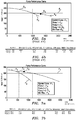
- Figure 1 depicts a two pump parallel system of identical pumps maintaining a constant head pressure of 61 m (200ft) with a demand of 0.095 m 3 /s (1500 gpm)
- Pump 2 is operated at a maximum fixed speed of 1780 rpm and generates 0.063 m 3 /s (1000 gpm).
- Pump 1 is used as the trim pump to make up the difference in flow which operates at 1641 rpm at 0.032 m 3 /s(500 gpm). This represents a 2:1 flow imbalance between the pumps.
- the result of this flow imbalance is Pump 1 running at 54% of the best efficiency point (BEP) and at a lower pumping efficiency compared to Pump 1. Both these factors can lead to higher operating cost and decreased pump reliability.
- this method leads to a flow dead band in which the only option to operate within this dead band region is to operate the trim pump below the manufactures recommended minimum flow.
- FIG. 2 depicts that same pump system as described in Figure 1 with the exception that the flow demand has been changed to 0.076 m 3 /s (1200 gpm).
- Pump 2 is running at a fixed maximum speed and can only produce 0.063 m 3 /s (1000 gpm). In this system Pump 1 must make up the additional 0.013 m 3 /s (200 gpm). This results in Pump 1 operating in the flow dead band region below the recommended minimum flow for the pump.
- this form of multi-pump control can lead to flow imbalances between the fixed speed and variable speed trim pump. This imbalance results in the trim pump being forced back on the pump performance curve which leads to lower pumping efficiencies, decreased pump reliability and uneven wear between the pumps.
- Examples of such known devices that contain this type of control include: ABB Pump Control Application Program for ACS800 Variable Speed Drive, and ABB Pump and Fan Application for ACH550 Variable Speed Drive.
- Synchronous Speed Control In this method of control in a multiple pump system, all pumps are operated with a variable speed drive and run together at a synchronous speed to achieve the desired setpoint.
- the objective of Synchronous Speed Control is to balance the flow of all pumps equally by having all pumps run at the same speed. However, in practice this may not necessarily result in balanced flow.
- the pumps are identical and maintaining a constant head pressure of 61 m (200 ft) with a demand of 0.076 m 3 /s (1200 gpm). To meet the demand of the system both pumps run at the same speed balancing the flow between the pumps and sharing the loads equally. Additionally an operation flow dead band is avoided.
- Figure 4 depicts an identical system to Figure 3 with the exception that Pump 2 is demonstrating 7% wear.
- Pump 1 and Pump 2 had identical hydraulics the flow was balanced 1:1.
- running the pumps together at a synchronous speed results in a 2:1 flow imbalance.
- Pump 2 can not generate the same head as Pump 1 it is forced back on the pump performance curve to compensate which lowers the pump efficiency and decreases pump reliability.
- Examples of devices that contain this type of control include: MULTITRODE MultiSmart Pump Controller / RTU, ITT PS200 Variable Speed Drive, and ITT Aquavar CPC Variable Speed Drive
- the present invention provides a new and unique method and apparatus for operating and running multiple pumps in a system together at a substantially synchronous torque to achieve a desired setpoint.
- Each of the multiple pumps may be operated with a variable speed drive.
- the apparatus of the present invention may take the form of a system having the multiple pumps with a system controller for operating and running the multiple pumps, the pump for operating and running in such a system, a system control module for such a system controller, as well as a pump control module for running and operating such a pump.
- the flow of the multiple pumps is substantially balanced even when pumps have different hydraulic head curves, including the multiple pumps having nearly 1:1 flow balance.
- Each respective pump may be controlled by a respective variable speed device that is configured to calculate a respective torque of a respective load of the respective pump, or each pump may be is controlled by any suitable respective device that can vary the speed of the pump.
- the method may also include providing a process variable and setpoint as inputs to a system controller, where the system controller includes either a PLC, DCS System, SCADA System or Variable Speed Drive.
- the system controller may be configured with logic that recognizes an error from the process variable to the setpoint and instructs a respective pump to increase or decrease torque and/or speed to maintain a desired setpoint, may be configured to recognize when an additional pump should be brought online or taken offline to match the demand of the system.
- the system controller may be configured to instruct a lead pump to increase or decrease torque/speed to meet the setpoint, and/or lag pumps will match torques to the lead pump and operate together in a synchronous torque mode, when the multiple pumps are running.
- the technique or device according to the present invention provides for balancing the flow between multiple pumps in the system.
- FIG. 6 is a functional block diagram of a system according to the present invention and generally indicated as 10 having a controller 12 that may take the form of, but not limited to, a VFD, PLC, DCS system, SCADA system that reads a process variable and determines the number of pumps required and at what torque to run the pumps in order to maintain a desired setpoint.
- the controller 12 is coupled to four variable speed drives (VSDs) 14a, 14b, 14c, 14d; four motors 16a, 16b, 16c, 16d; and four pumps 18a, 18b, 18c, 18d.
- VSDs variable speed drives
- the variable speed drive 14a is a lead VSD.
- variable speed drives VSDs
- motors and pumps The system is described by way of example having four variable speed drives (VSDs), motors and pumps, although the scope of the invention is not intended to be limited to the number of variable speed drives (VSDs), motors and pumps. Embodiments are envisioned, and the scope of the invention is intended to include, systems having a different number of variable speed drives (VSDs), motors and pumps, including a numbers such as two, three, five, six, etc. Moreover, variable speed drives (VSDs), motors and pumps are all known in the art, and the scope of the invention is not intended to be limited to any particular type or kind thereof either now known or later developed in the future. ,
- the controller 12 is configured to receive signalling containing information about a setpoint and/or one or more process variables, and to provide a controller output to the lead VSD 14a.
- the lead VSD 14a is configured to provide one or more torque signals to the other three variable speed drives (VSDs) 14b, 14c, 14d.
- VSDs variable speed drives
- the controller 12 and the four VSDs 14a, 14b, 14c, 14d are also configured to exchange drive available/on-off signalling.
- the system is described by way of example with the controller 12 configured to receive signalling containing information about the setpoint and the one or more process variables; however, the scope of the invention is not intended to be limited to the type or kind of information received by the controller 12.
- embodiments are envisioned within the scope of the invention in which the controller is configured to receive signalling containing other types or kinds of information either now known or later developed in the future.
- the lead VSD 14a is configured to respond to the controller output, and the other three VSDs 14a, 14b, 14c, 14d are configured to respond to the one or more torque signals, and the four VSDs 14a, 14b, 14c, 14d are configured to provide respective VSD signalling containing information about variable speeds for driving the four motors 16a, 16b, 16c, 16d.
- the four motors 16a, 16b, 16c, 16d are configured to respond to respective VSD signalling and to drive the four pumps 18a, 18b, 18c, 18d.
- the controller 12 may reside internal or external to the lead VSD 14a. Moreover, the scope of the invention is not intended to be limited to where the multipump controller 12 is implemented within the overall system 10.
- all four pumps 18a, 18b, 18c, 18d may be operated with a variable speed drive (VSD) and run together at a substantially synchronous torque to achieve the desired setpoint.
- VSD variable speed drive
- the objective of Synchronous Speed Torque is to balance the flow of the four pumps 18a, 18b, 18c, 18d even when the four pumps 18a, 18b, 18c, 18d have different hydraulic head curves.
- Substantially Synchronous Torque is understood to mean that the driven equipment, such as a pump, is operated in a manner as such the operating torques of the driven equipment are substantially balanced within, for example, a minimum range of about 95% of the true operating torque between the driven equipment.
- the controller 12 will continuously update and communicate an identical torque setpoint to each piece of driven equipment as determined necessary to maintain the desired feedback of a pump system. The driven equipment will then feedback the true operating torque to the controller to confirm each piece of driven equipment is operating within the required about 95% operating window.
- This form of control allows pumps to be operated in parallel that experience mechanical and hydraulic wear, have different impeller trims, have different head performance curves or are even manufactured by different pump manufactures.
- Each pump is controlled by a variable speed device that has the ability to calculate the torque of the drive's load, in this case the pump.
- a variable frequency drive is used as the variable speed device, but this control method is applicable to any device that can vary the pump speed.
- torque is expressed in real units such as Nm. Torque should not be expressed as a percentage of motor full load motor torque as this would limit the functionality to only using identical motors or motors that generate the same full load torque. However, if the motors are identical expressing torque as a percentage of full load would be acceptable to use.
- the system operates in which a process variable and setpoint are input to a system controller.
- This system controller can be in the form of but, not limited to a PLC, DCS System, SCADA System or Variable Speed Drive.
- the system controller is configured to contain some form of logic that recognizes the error from the process variable to the setpoint and instructs a pump to increase or decrease torque and/or speed to maintain the desired setpoint.
- This system controller is also configured to contain an ability to recognize when an additional pump should be brought online or taken offline to match the system demand.
- Figure G depicts the control layout for a four pump system.
- the pumps shall always maintain substantially the same torques levels with the following exceptions in which case the synchronous torque mode will be overridden by synchronous speed control, as follows:
- the lag pumps shall synchronize speeds with the lead pump to allow the lag pumps to get to maximum speed.
- This override allows the pumps to generate maximum output while sacrificing the flow balance of the pumps. This override function shall be user selectable.
- the functionality of the multipump controller 12 may be implemented with one or more modules using hardware, software, firmware, or a combination thereof.
- the one or more modules that form part of the multipump controller 12 would include one or more microprocessor-based architectures having a microprocessor, a random access memory (RAM), a read only memory (ROM), input/output devices and control, data and address buses connecting the same.
- RAM random access memory
- ROM read only memory
- input/output devices control, data and address buses connecting the same.
- a person skilled in the art would appreciate and be able to program such a microprocessor-based implementation to perform the functionality described herein without undue experimentation.
- the scope of the invention is not intended to be limited to any particular implementation using some combination of hardware, software, or firmware technology either now known or later developed in the future.
- the Multipump Controller 12 as a Chipset
- the one or more modules of the controller may also form part of a basic chipset implementation.
- the present invention may also take the form of the chipset that may include a number of integrated circuits designed to perform one or more related functions, including a chipset or chip formed as a group of integrated circuits, or chips, that are designed to work together.
- one chipset may provide the basic functions of the overall controller, while another chipset may provide control processing unit (CPU) functions for a computer or processor in overall controller.
- Newer chipsets generally include functions provided by two or more older chipsets. In some cases, older chipsets that required two or more physical chips can be replaced with a chipset on one chip.
- the term "chipset" is also intended to include the core functionality of a motherboard in such a controller.
- Synchronous Torque Control can be applied to multiple pump systems in parallel or in series. Additionally this logic can be applied to multiple fan/blower systems.
Landscapes
- Engineering & Computer Science (AREA)
- Mechanical Engineering (AREA)
- General Engineering & Computer Science (AREA)
- Software Systems (AREA)
- Evolutionary Computation (AREA)
- Medical Informatics (AREA)
- Health & Medical Sciences (AREA)
- Physics & Mathematics (AREA)
- General Physics & Mathematics (AREA)
- Automation & Control Theory (AREA)
- Computer Vision & Pattern Recognition (AREA)
- Artificial Intelligence (AREA)
- Control Of Positive-Displacement Pumps (AREA)
- Control Of Non-Positive-Displacement Pumps (AREA)
Description
- The present invention relates to a method and apparatus for control in a system having multiple pumps.
-
EP 0 735 273 A1 - There are known devices or controllers that include, but are not limited to, Programmable Logic Controllers (PLC), Distributed Control Systems (DCS), Supervisory Control and Data Acquisition (SCADA) Systems or Variable Speed Drive Macros which coordinate the control of a multiple pump system. These controllers typically use two methods of control that can negatively affect overall pump performance and efficiency as follows:
- ▪ Fixed Speed Pumps with Variable Speed Trim Pump and
- ▪ Multiple Pump Synchronous Speed.
- Fixed speed pumps with variable speed trim pump have following shortcomings:
- In this method of control in a multiple pump system, slave pump(s) are operated at a fixed maximum speed and one master trim pump is operated by a variable speed drive which varies the speed of this pump to trim or make up the difference to meet the desired setpoint; typically level, pressure or flow control. The master pump determines how many fixed speed slave drives should be staged or destaged.
- The shortcoming of this method of control is that by basic pump system hydraulics the variable speed trim pump must generate enough head pressure to overcome the pressure in which the fixed speed pump is providing into the discharge header. In order for the trim pump to generate the required pressure at the reduced speed, the variable speed trim pump will be forced back on the pump performance curve which can cause lower operating efficiencies and decreased reliability. This type of control leads to a flow imbalance between the fixed speed pump and variable speed trim pump. In the worst case the variable speed trim pump may operate in a shutoff or deadhead condition.
-
Figure 1 depicts a two pump parallel system of identical pumps maintaining a constant head pressure of 61 m (200ft) with a demand of 0.095 m3/s (1500 gpm)Pump 2 is operated at a maximum fixed speed of 1780 rpm and generates 0.063 m3/s (1000 gpm).Pump 1 is used as the trim pump to make up the difference in flow which operates at 1641 rpm at 0.032 m3/s(500 gpm). This represents a 2:1 flow imbalance between the pumps. The result of this flow imbalance isPump 1 running at 54% of the best efficiency point (BEP) and at a lower pumping efficiency compared toPump 1. Both these factors can lead to higher operating cost and decreased pump reliability. - Ultimately, this method leads to a flow dead band in which the only option to operate within this dead band region is to operate the trim pump below the manufactures recommended minimum flow.
-
Figure 2 depicts that same pump system as described inFigure 1 with the exception that the flow demand has been changed to 0.076 m3/s (1200 gpm).Pump 2 is running at a fixed maximum speed and can only produce 0.063 m3/s (1000 gpm). In thissystem Pump 1 must make up the additional 0.013 m3/s (200 gpm). This results inPump 1 operating in the flow dead band region below the recommended minimum flow for the pump. - In conclusion, this form of multi-pump control can lead to flow imbalances between the fixed speed and variable speed trim pump. This imbalance results in the trim pump being forced back on the pump performance curve which leads to lower pumping efficiencies, decreased pump reliability and uneven wear between the pumps.
- Examples of such known devices that contain this type of control include: ABB Pump Control Application Program for ACS800 Variable Speed Drive, and ABB Pump and Fan Application for ACH550 Variable Speed Drive.
- In this method of control in a multiple pump system, all pumps are operated with a variable speed drive and run together at a synchronous speed to achieve the desired setpoint. The objective of Synchronous Speed Control is to balance the flow of all pumps equally by having all pumps run at the same speed. However, in practice this may not necessarily result in balanced flow.
- As demonstrated in
Figure 3 , the pumps are identical and maintaining a constant head pressure of 61 m (200 ft) with a demand of 0.076 m3/s (1200 gpm). To meet the demand of the system both pumps run at the same speed balancing the flow between the pumps and sharing the loads equally. Additionally an operation flow dead band is avoided. - The shortcoming of this method is in order to achieve a flow balance between the pumps the head curve of the pumps must be identical or very closely matched. In theory this method should always maintain a balance flow between the pumps provide they are identical and hydraulically and mechanically wear evenly. However, in practice this situation can be very difficult to maintain as pumps can wear unevenly or a pump with slightly different hydraulics can be added to a pump system at a different time. It is these factors that can lead to a flow imbalance between the pumps and in a severe case lead to a pump not producing any flow.
-
Figure 4 depicts an identical system toFigure 3 with the exception thatPump 2 is demonstrating 7% wear. WhenPump 1 andPump 2 had identical hydraulics the flow was balanced 1:1. In this example running the pumps together at a synchronous speed results in a 2:1 flow imbalance. BecausePump 2 can not generate the same head asPump 1 it is forced back on the pump performance curve to compensate which lowers the pump efficiency and decreases pump reliability. - In a severe case (
Figure 5 ) in whichPump 2 demonstrates a 20% loss inhead capacity Pump 1 will completely overpower Pump 2. In thissituation Pump 2 will not be able to overcome the pressure generated byPump 1 and will produce no flow causing a dead head situation. - In conclusion, while the Synchronous Speed Control known in the art is intended to balance the flow between pumps in parallel it relies on pumps having identical head capacity curves. Any deviation from this such as pump wear or using pumps with different hydraulics will result in a flow imbalance and in extreme circumstances a no flow situation.
- Examples of devices that contain this type of control include: MULTITRODE MultiSmart Pump Controller / RTU, ITT PS200 Variable Speed Drive, and ITT Aquavar CPC Variable Speed Drive
- In view of this, there is a need in the industry for a technique or device for balancing the flow between multiple pumps in a system.
- The present invention provides a new and unique method and apparatus for operating and running multiple pumps in a system together at a substantially synchronous torque to achieve a desired setpoint. Each of the multiple pumps may be operated with a variable speed drive.
- The apparatus of the present invention may take the form of a system having the multiple pumps with a system controller for operating and running the multiple pumps, the pump for operating and running in such a system, a system control module for such a system controller, as well as a pump control module for running and operating such a pump.
- According to the present invention, the flow of the multiple pumps is substantially balanced even when pumps have different hydraulic head curves, including the multiple pumps having nearly 1:1 flow balance.
- Each respective pump may be controlled by a respective variable speed device that is configured to calculate a respective torque of a respective load of the respective pump, or each pump may be is controlled by any suitable respective device that can vary the speed of the pump.
- The method may also include providing a process variable and setpoint as inputs to a system controller, where the system controller includes either a PLC, DCS System, SCADA System or Variable Speed Drive. The system controller may be configured with logic that recognizes an error from the process variable to the setpoint and instructs a respective pump to increase or decrease torque and/or speed to maintain a desired setpoint, may be configured to recognize when an additional pump should be brought online or taken offline to match the demand of the system.
- The system controller may be configured to instruct a lead pump to increase or decrease torque/speed to meet the setpoint, and/or lag pumps will match torques to the lead pump and operate together in a synchronous torque mode, when the multiple pumps are running.
- In operation, the technique or device according to the present invention provides for balancing the flow between multiple pumps in the system.
- The drawing includes the following Figures:
-
Figure 1 , includingFigures 1a and 1b , is a graph and a table of a two pump parallel system known in the art of identical pumps with one pump running at a fixed maximum speed and the other pump is running in a variable speed mode maintaining a constant head pressure of 61 m (200 ft) with a demand of 0.095 m3/s (1500 gpm). -
Figure 2 , includingFigures 2a and 2b , is a graph and a table of the same pump system as shown inFigure 1 with the exception that the flow demand has been changed to 0.076 m3/s (1200 gpm). -
Figure 3 , includingFigures 3a and 3b , is a graph and a table of pumps that are identical with both pumps running in a synchronous variable speed mode maintaining a constant head pressure of 61 m (200 ft) with a demand of 0.076 m3/s (1200 gpm). -
Figure 4 , includingFigures 4a and 4b , is a graph and a table of an identical system to that shown inFigure 3 with the exception thatPump 2 is demonstrating 7% wear.Figure 5 , includingFigures 5a and 5b , is a graph of an identical system to that shown inFigure 4 with the exception thatPump 2 is demonstrating 20% wear. -
Figure 6 is a functional block diagram of a controller in the form, but not limited to, a VFD, PLC, DCS system, SCADA system that reads a process variable and determines the number of pumps required and at what torque to run the pumps in order to maintain the desired setpoint. -
Figure 7 , includingFigures 7a and 7b , is a graph of an identical system to that shown inFigure 4 with the exception that both pumps are run in a synchronous torque mode. -
Figure 6 is a functional block diagram of a system according to the present invention and generally indicated as 10 having acontroller 12 that may take the form of, but not limited to, a VFD, PLC, DCS system, SCADA system that reads a process variable and determines the number of pumps required and at what torque to run the pumps in order to maintain a desired setpoint. Thecontroller 12 is coupled to four variable speed drives (VSDs) 14a, 14b, 14c, 14d; fourmotors pumps variable speed drive 14a is a lead VSD. The system is described by way of example having four variable speed drives (VSDs), motors and pumps, although the scope of the invention is not intended to be limited to the number of variable speed drives (VSDs), motors and pumps. Embodiments are envisioned, and the scope of the invention is intended to include, systems having a different number of variable speed drives (VSDs), motors and pumps, including a numbers such as two, three, five, six, etc. Moreover, variable speed drives (VSDs), motors and pumps are all known in the art, and the scope of the invention is not intended to be limited to any particular type or kind thereof either now known or later developed in the future. , - In operation, as shown the
controller 12 is configured to receive signalling containing information about a setpoint and/or one or more process variables, and to provide a controller output to thelead VSD 14a. In response, thelead VSD 14a is configured to provide one or more torque signals to the other three variable speed drives (VSDs) 14b, 14c, 14d. As shown, thecontroller 12 and the fourVSDs controller 12 configured to receive signalling containing information about the setpoint and the one or more process variables; however, the scope of the invention is not intended to be limited to the type or kind of information received by thecontroller 12. For example, embodiments are envisioned within the scope of the invention in which the controller is configured to receive signalling containing other types or kinds of information either now known or later developed in the future. - The
lead VSD 14a is configured to respond to the controller output, and the other threeVSDs VSDs motors motors pumps - As shown, and indicated by the circled hatched lines, the
controller 12 may reside internal or external to thelead VSD 14a. Moreover, the scope of the invention is not intended to be limited to where themultipump controller 12 is implemented within theoverall system 10. - In this method of control in a multiple pump system according to the present invention, all four
pumps pumps pumps - In one particular application, the term Substantially Synchronous Torque is understood to mean that the driven equipment, such as a pump, is operated in a manner as such the operating torques of the driven equipment are substantially balanced within, for example, a minimum range of about 95% of the true operating torque between the driven equipment. To achieve Substantially Synchronous Torque Control, the
controller 12 will continuously update and communicate an identical torque setpoint to each piece of driven equipment as determined necessary to maintain the desired feedback of a pump system. The driven equipment will then feedback the true operating torque to the controller to confirm each piece of driven equipment is operating within the required about 95% operating window. However, it is noteworthy that the scope of the invention is not intended to be limited to any particular percentage in order to achieve Substantially Synchronous Torque according to the present invention. For example, as a person skilled in the art would appreciate, depending on the type or kind of application, including those now known or later developed in the future, embodiments of the invention may include using another percentage above or below about 95% and still operate within the spirit of the present invention. - By balancing the torque between the four
pumps pumps Figure 4 , where two pumps in synchronous speed control are pumping in parallel andPump 2 is demonstrating a 7% degradation in head due to wear, a flow imbalance occurs of nearly 2:1. If this same system is placed in substantially Synchronous Torque according to the present invention, the result would be a nearly 1:1 flow balance. As depicted inFigure 7 , the pumps are running at the same torque of 198 Nm (146 ft.lbs), as a result the pumps run at a 104 rpm differential and produce a near 1:1 flow balance. - This form of control allows pumps to be operated in parallel that experience mechanical and hydraulic wear, have different impeller trims, have different head performance curves or are even manufactured by different pump manufactures.
- Each pump is controlled by a variable speed device that has the ability to calculate the torque of the drive's load, in this case the pump. Typically, a variable frequency drive is used as the variable speed device, but this control method is applicable to any device that can vary the pump speed. In this system, torque is expressed in real units such as Nm. Torque should not be expressed as a percentage of motor full load motor torque as this would limit the functionality to only using identical motors or motors that generate the same full load torque. However, if the motors are identical expressing torque as a percentage of full load would be acceptable to use.
- The system operates in which a process variable and setpoint are input to a system controller. This system controller can be in the form of but, not limited to a PLC, DCS System, SCADA System or Variable Speed Drive. The system controller is configured to contain some form of logic that recognizes the error from the process variable to the setpoint and instructs a pump to increase or decrease torque and/or speed to maintain the desired setpoint. This system controller is also configured to contain an ability to recognize when an additional pump should be brought online or taken offline to match the system demand.
- When multiple pumps are running, the system controller shall instruct a lead pump to increase or decrease torque/speed to meet the setpoint. Lag pumps will match torques to the lead pump and operate together in a synchronous torque mode. Figure G depicts the control layout for a four pump system.
- In this mode, the pumps shall always maintain substantially the same torques levels with the following exceptions in which case the synchronous torque mode will be overridden by synchronous speed control, as follows:
- 1. All available pumps are running and the setpoint cannot be met and at least one lag unit is not at maximum speed.
- 2. A lag pump unit is at maximum speed and cannot attain synchronous torque.
- If all of these conditions occur, then the lag pumps shall synchronize speeds with the lead pump to allow the lag pumps to get to maximum speed. This override allows the pumps to generate maximum output while sacrificing the flow balance of the pumps. This override function shall be user selectable.
- Consistent with that described above, the functionality of the
multipump controller 12 may be implemented with one or more modules using hardware, software, firmware, or a combination thereof. In a typical software implementation, the one or more modules that form part of themultipump controller 12 would include one or more microprocessor-based architectures having a microprocessor, a random access memory (RAM), a read only memory (ROM), input/output devices and control, data and address buses connecting the same. A person skilled in the art would appreciate and be able to program such a microprocessor-based implementation to perform the functionality described herein without undue experimentation. The scope of the invention is not intended to be limited to any particular implementation using some combination of hardware, software, or firmware technology either now known or later developed in the future. - In some embodiments according to the present invention, the one or more modules of the controller may also form part of a basic chipset implementation. The present invention may also take the form of the chipset that may include a number of integrated circuits designed to perform one or more related functions, including a chipset or chip formed as a group of integrated circuits, or chips, that are designed to work together. For example, one chipset may provide the basic functions of the overall controller, while another chipset may provide control processing unit (CPU) functions for a computer or processor in overall controller. Newer chipsets generally include functions provided by two or more older chipsets. In some cases, older chipsets that required two or more physical chips can be replaced with a chipset on one chip. The term "chipset" is also intended to include the core functionality of a motherboard in such a controller.
- Other possible applications include at least the following: Synchronous Torque Control can be applied to multiple pump systems in parallel or in series. Additionally this logic can be applied to multiple fan/blower systems.
- It should be understood that, unless stated otherwise herein, any of the features, characteristics, alternatives or modifications described regarding a particular embodiment herein may also be applied, used, or incorporated with any other embodiment described herein. Also, the drawings herein are not drawn to scale.
- Although the invention has been described and illustrated with respect to exemplary embodiments thereof, the foregoing and various other additions and omissions may be made therein and thereto without departing from the scope of the present invention which is solely defined by the appended claims.
Claims (13)
- A method of control in a system having multiple pumps (18a-18d), wherein the multiple pumps (18a-18d) are operated and run together at a substantially synchronous torque to achieve a desired setpoint, wherein the method comprises:responding with a controller (12) to signaling containing information about the desired setpoint, and providing a control output signal;responding with a lead variable speed drive (14a) to the control output signal,providing a lead variable speed drive signal for driving one of the multiple pumps (18a), and also providing one or more torque signals; andresponding with a lag variable speed drive (14b; 14c; 14d) to the one or more torque signals, and providing a lag variable speed drive signal for driving another one of the multiple pumps (18b; 18c; 18d);the one or more torque signals containing information so that the lead variable speed drive (14a) and the lag variable speed drive (14b; 14c; 14d) operate and run the multiple pumps together at the substantially synchronous torque to achieve the desired setpoint.
- The method according to claim 1, wherein the flow of the pump (18a; 18b; 18c; 18d) or of the multiple pumps (18a-18d) is substantially balanced even when pumps (18a-18d) have different hydraulic head curves.
- The method according to one of the preceding claims, wherein the multiple pumps (18a-18d) have nearly 1:1 flow balance.
- The method according to one of the preceding claims, wherein each respective pump (18a; 18b; 18c; 18d) is controlled by a respective variable speed device (VSD) that is configured to calculate a respective torque of a respective load of the respective pump (18a; 18b; 18c; 18d); and/or- a respective device that can vary the speed of the pump (18a; 18b; 18c; 18d).
- The method according to one of the preceding claims, wherein the method includes providing a process variable and setpoint as inputs to a system controller (12).
- The method according to claim 5, wherein the system controller (12)- includes either a PLC, DCS System, SCADA System or Variable Speed Drive (VSD);- contains logic that recognizes an error from the process variable to the setpoint and instructs the respective pump (18a; 18b; 18c; 18d) to increase or decrease torque and/or speed to maintain a desired setpoint;- is configured to recognize when an additional pump (18a; 18b; 18c; 18d) should be brought online or taken offline to match the demand of the system; and/or- is configured to instruct a lead pump (18a) to increase or decrease torque/speed to meet the setpoint when the multiple pumps (18a; 18b; 18c; 18d) are running, and in particular wherein lag pumps (18b-18d) will match torques to the lead pump (18a) and operate together in a synchronous torque mode when the multiple pumps (18a; 18b; 18c; 18d) are running.
- A system having multiple pumps (18a-18d), wherein the multiple pumps (18a-18d) are operated and run together at a substantially synchronous torque to achieve a desired setpoint, wherein the system comprises:a controller (12) configured to respond to signaling containing information about the desired setpoint, and providing a control output signal;a lead variable speed drive (14a) configured to respond to the control output signal, to provide a lead variable speed drive signal for driving one of the multiple pumps (18a), and also providing one or more torque signals; anda lag variable speed drive (14b; 14c; 14d) configured to respond to the one or more torque signals, and to provide a lag variable speed drive signal for driving another one of the multiple pumps (18b; 18c; 18d);the one or more torque signals containing information so that the lead variable speed drive (14a) and the lag variable speed drive (14b; 14c; 14d) operate and run the multiple pumps together at the substantially synchronous torque to achieve the desired setpoint.
- The system according to claim 7, wherein the flow of the pumps (18a; 18b; 18c; 18d) is substantially balanced with the flow of the one or more other pumps (18a; 18b; 18c; 18d) so that the multiple pumps (18a; 18b; 18c; 18d) have nearly 1:1 flow balance.
- A lead pump (18a) for a system having multiple pumps (18a-18d), wherein the multiple pumps (18a-18d) are operated and run together at a substantially synchronous torque to achieve a desired setpoint, wherein the lead pump (18a) comprises a module configured to operate and run the lead pump (18a) at a substantially synchronous torque to achieve a desired setpoint:wherein the lead pump (18a) is configured to receive a control output signal from a controller (12) which is configured to respond to signaling containing information about the desired setpoint; the lead pump (18a) further comprising:a lead variable speed drive (14a) configured to respond to the control output signal, to provide a lead variable speed drive signal for driving one of the multiple pumps (18a-18d), and also to provide one or more torque signals to be received by a lag variable speed drive (14b; 14c; 14d) for driving another one of the multiple pumps (18b; 18c; 18d);the one or more torque signals containing information so that the lead variable speed drive (14a) and the lag variable speed drive (14b; 14c; 14d) operate and run the multiple pumps together at the substantially synchronous torque to achieve the desired setpoint.
- The lead pump (18a) according to claim 9, wherein the module- includes a variable speed device (VSD) that is configured to calculate a respective torque of a respective load of the respective pump (18a);- includes a respective device that can vary the speed of the pump (18a); and/or- receives signals from a system controller (16) that receives a process variable and setpoint.
- The lead pump (18a) according to claim 9 or 10, wherein the system controller (16) is configured to instruct the lead pump (18a) to increase or decrease torque/speed to meet the setpoint when the multiple pumps are running, and the module is configured to respond to that instruction.
- A system control module. (12) configured to control a system according to one of the claims 7 and 8, and configured to implement a method according to one of the claims 1 to 6.
- A pump control module configured to control a pump according to one of the claims 9 to 11, and configured to implement a method according to one of the claims 1 to 6.
Priority Applications (1)
| Application Number | Priority Date | Filing Date | Title |
|---|---|---|---|
| PL08861340T PL2229610T3 (en) | 2007-12-14 | 2008-12-15 | Synchronous torque balance in multiple pump systems |
Applications Claiming Priority (2)
| Application Number | Priority Date | Filing Date | Title |
|---|---|---|---|
| US1368507P | 2007-12-14 | 2007-12-14 | |
| PCT/US2008/086803 WO2009079447A1 (en) | 2007-12-14 | 2008-12-15 | Synchronous torque balance in multiple pump systems |
Publications (3)
| Publication Number | Publication Date |
|---|---|
| EP2229610A1 EP2229610A1 (en) | 2010-09-22 |
| EP2229610A4 EP2229610A4 (en) | 2014-03-26 |
| EP2229610B1 true EP2229610B1 (en) | 2019-03-06 |
Family
ID=40795889
Family Applications (1)
| Application Number | Title | Priority Date | Filing Date |
|---|---|---|---|
| EP08861340.1A Active EP2229610B1 (en) | 2007-12-14 | 2008-12-15 | Synchronous torque balance in multiple pump systems |
Country Status (6)
| Country | Link |
|---|---|
| US (1) | US8328523B2 (en) |
| EP (1) | EP2229610B1 (en) |
| CN (1) | CN101896871B (en) |
| FI (1) | FI125614B (en) |
| PL (1) | PL2229610T3 (en) |
| WO (1) | WO2009079447A1 (en) |
Cited By (1)
| Publication number | Priority date | Publication date | Assignee | Title |
|---|---|---|---|---|
| RU2736136C1 (en) * | 2020-03-24 | 2020-11-11 | Общество с ограниченной ответственностью "Газпром добыча Ямбург" | Method of automatic control of gas condensate supply process into main condensate line |
Families Citing this family (24)
| Publication number | Priority date | Publication date | Assignee | Title |
|---|---|---|---|---|
| US8180496B2 (en) * | 2008-03-05 | 2012-05-15 | Metropolitan Industries, Inc. | System and method of constant pressure, variable speed pump control with local equalization for dissimilar pumps |
| US8801407B2 (en) * | 2010-02-24 | 2014-08-12 | Harris Waste Management Group, Inc. | Hybrid electro-hydraulic power device |
| US8579599B2 (en) * | 2010-03-26 | 2013-11-12 | Schlumberger Technology Corporation | System, apparatus, and method for rapid pump displacement configuration |
| PE20130791A1 (en) * | 2010-04-07 | 2013-07-25 | Weir Minerals Netherlands Bv | PHASE DISPLACEMENT CONTROLLER FOR AN ALTERNATIVE PUMP SYSTEM |
| NL2004979C2 (en) * | 2010-04-07 | 2011-10-10 | Weir Minerals Netherlands Bv | Phase shift controller for a reciprocating pump system. |
| US20110286866A1 (en) * | 2010-04-20 | 2011-11-24 | Hancock Sr Leonard H | AC Power Unit Operating System For Emergency Vehicles |
| WO2012151588A1 (en) * | 2011-05-05 | 2012-11-08 | Eksigent Technologies, Llc | Ganging electrokinetic pumps |
| US20130048114A1 (en) * | 2011-08-26 | 2013-02-28 | Optimum Energy, Llc | Controlled hydronic distribution system |
| CA2856447C (en) * | 2011-12-16 | 2019-06-04 | Fluid Handling Llc | Dynamic linear control methods and apparatus for variable speed pump control |
| EP2932342B1 (en) | 2012-12-12 | 2021-05-19 | S. A. Armstrong Limited | Co-ordinated sensorless control system |
| CN104884809B (en) * | 2012-12-17 | 2017-09-15 | Itt制造企业有限责任公司 | Optimisation technique for the pump in multiple pump being classified and being gone classification |
| EP2984346B1 (en) | 2013-04-12 | 2021-12-22 | Pentair Pump Group, Inc. | Water booster control system and method |
| RU2551139C1 (en) * | 2013-11-21 | 2015-05-20 | Государственное бюджетное образовательное учреждение высшего профессионального образования "Альметьевский государственный нефтяной институт" | Pump station electric drive automatic control method |
| DE102014006258A1 (en) | 2014-04-30 | 2015-11-05 | Wilo Se | Method for controlling a pump system and regulated pump system |
| EP2947325B1 (en) * | 2014-05-23 | 2019-12-04 | Grundfos Holding A/S | Pump control method |
| JP2016160792A (en) * | 2015-02-27 | 2016-09-05 | 株式会社川本製作所 | Pump unit and pump control method |
| US10566881B2 (en) | 2017-01-27 | 2020-02-18 | Franklin Electric Co., Inc. | Motor drive system including removable bypass circuit and/or cooling features |
| EP3369934B1 (en) * | 2017-03-03 | 2024-12-11 | Grundfos Holding A/S | Circulation pump |
| DE102017203926A1 (en) * | 2017-03-09 | 2018-09-13 | KSB SE & Co. KGaA | Method for operating a circulating pump in twin construction |
| US10533562B2 (en) * | 2017-04-03 | 2020-01-14 | Honeywell International Inc. | Pump selection using dynamic priority numbers |
| WO2018207246A1 (en) * | 2017-05-09 | 2018-11-15 | 本田技研工業株式会社 | General-purpose engine control device |
| US20170254333A1 (en) * | 2017-05-19 | 2017-09-07 | LT Lighting (Taiwan) Corp. | Multi-pump system with system check |
| EP3428453B1 (en) | 2017-07-14 | 2023-06-07 | Grundfos Holding A/S | Multi-pump control keeping the head constant while ramping up or down a subset of the pumps |
| TWI779373B (en) * | 2020-10-26 | 2022-10-01 | 復盛股份有限公司 | Compressor system with frequency modulation control and control method of frequency modulation the same |
Citations (1)
| Publication number | Priority date | Publication date | Assignee | Title |
|---|---|---|---|---|
| US20020136642A1 (en) * | 1999-07-12 | 2002-09-26 | Moller Eik Sefeldt | Method for regulating a delivery variable of a pump |
Family Cites Families (17)
| Publication number | Priority date | Publication date | Assignee | Title |
|---|---|---|---|---|
| US4308491A (en) | 1980-05-05 | 1981-12-29 | Square D Company | Automatic fault protection system for power recovery control |
| US4502842A (en) | 1983-02-02 | 1985-03-05 | Colt Industries Operating Corp. | Multiple compressor controller and method |
| US5092824A (en) | 1990-10-09 | 1992-03-03 | Connett Donald C | Pump output control system with high efficiency hydromechanical variable speed drive |
| DE4128390C1 (en) * | 1991-08-27 | 1992-12-24 | Loewe Pumpenfabrik Gmbh, 2120 Lueneburg, De | Rapid control appts. for fluid supply installation - has controller connected via digital communication line to pump motor regulators which provide setting signals for frequency converters |
| US5422550A (en) | 1993-05-27 | 1995-06-06 | Southwest Electric Company | Control of multiple motors, including motorized pumping system and method |
| US5522707A (en) | 1994-11-16 | 1996-06-04 | Metropolitan Industries, Inc. | Variable frequency drive system for fluid delivery system |
| DE19511170A1 (en) | 1995-03-28 | 1996-10-02 | Wilo Gmbh | Double pump with higher-level control |
| US5789879A (en) | 1995-11-03 | 1998-08-04 | Cook; Noel R. | Multiple pump hydraulic power system |
| JP3900219B2 (en) * | 1997-10-24 | 2007-04-04 | 株式会社安川電機 | Electric motor speed control device and gain setting method for the same |
| US6257833B1 (en) | 2000-01-04 | 2001-07-10 | Metropolitan Industries, Inc. | Redundant, dedicated variable speed drive system |
| US6394120B1 (en) | 2000-10-06 | 2002-05-28 | Scales Air Compressor | Method and control system for controlling multiple compressors |
| BR0103443A (en) * | 2001-08-21 | 2004-03-09 | Petroleo Brasileiro Sa | Multiphase Pumping System and Method |
| US7010393B2 (en) * | 2002-06-20 | 2006-03-07 | Compressor Controls Corporation | Controlling multiple pumps operating in parallel or series |
| US6933687B2 (en) | 2002-10-03 | 2005-08-23 | Siemens Vdo Automotive Inc. | Dual motor configuration with primary brushless motor and secondary integrated speed control motor |
| US20040193330A1 (en) | 2003-03-26 | 2004-09-30 | Ingersoll-Rand Company | Method and system for controlling compressors |
| US7080508B2 (en) * | 2004-05-13 | 2006-07-25 | Itt Manufacturing Enterprises, Inc. | Torque controlled pump protection with mechanical loss compensation |
| CN1749890A (en) * | 2005-10-20 | 2006-03-22 | 南开大学 | Smart Predictive Adaptive Controller |
-
2008
- 2008-12-15 CN CN200880119856.3A patent/CN101896871B/en active Active
- 2008-12-15 WO PCT/US2008/086803 patent/WO2009079447A1/en not_active Ceased
- 2008-12-15 EP EP08861340.1A patent/EP2229610B1/en active Active
- 2008-12-15 US US12/335,001 patent/US8328523B2/en active Active
- 2008-12-15 PL PL08861340T patent/PL2229610T3/en unknown
-
2010
- 2010-06-08 FI FI20105650A patent/FI125614B/en not_active IP Right Cessation
Patent Citations (1)
| Publication number | Priority date | Publication date | Assignee | Title |
|---|---|---|---|---|
| US20020136642A1 (en) * | 1999-07-12 | 2002-09-26 | Moller Eik Sefeldt | Method for regulating a delivery variable of a pump |
Cited By (1)
| Publication number | Priority date | Publication date | Assignee | Title |
|---|---|---|---|---|
| RU2736136C1 (en) * | 2020-03-24 | 2020-11-11 | Общество с ограниченной ответственностью "Газпром добыча Ямбург" | Method of automatic control of gas condensate supply process into main condensate line |
Also Published As
| Publication number | Publication date |
|---|---|
| FI125614B (en) | 2015-12-15 |
| EP2229610A1 (en) | 2010-09-22 |
| FI20105650L (en) | 2010-06-08 |
| PL2229610T3 (en) | 2019-08-30 |
| US20090304521A1 (en) | 2009-12-10 |
| CN101896871A (en) | 2010-11-24 |
| US8328523B2 (en) | 2012-12-11 |
| EP2229610A4 (en) | 2014-03-26 |
| WO2009079447A1 (en) | 2009-06-25 |
| CN101896871B (en) | 2015-06-10 |
Similar Documents
| Publication | Publication Date | Title |
|---|---|---|
| US8328523B2 (en) | Synchronous torque balance in multiple pump systems | |
| CN113323930A (en) | Multistage pressure control and pressure speed regulation hydraulic system and operation machinery | |
| JP2022130375A (en) | MULTI-STAGE COMPRESSOR AND METHOD FOR ADJUSTING ROTATING SPEED OF MOTOR | |
| TWI704285B (en) | Method for controlling motor-driven pump in a fluid system | |
| CN106068389A (en) | Electronic torque and Stress control for load-sensing pump | |
| EP1256375B1 (en) | Device and method for continuous high-pressure treatment | |
| WO2016198497A1 (en) | Load-sharing in parallel fluid pumps | |
| CN104884809B (en) | Optimisation technique for the pump in multiple pump being classified and being gone classification | |
| EP3670929B1 (en) | Hydraulic pump arrangement | |
| JP4329435B2 (en) | Pump operation system | |
| CN105422681B (en) | Hydro-viscous speed governing clutch control method based on dynamic PID control | |
| RU2674293C2 (en) | Variable speed multi-pump device for providing energy saving by calculating and compensating for friction loss using speed reference | |
| ES2729618T3 (en) | Synchronous torque balance in multiple pump systems | |
| US12173844B2 (en) | High efficiency seal oil system | |
| RU2760278C2 (en) | Method for operation of a dual-structure circulation pump | |
| Paszota | Energy Saving in a Hydraulic Servomechanism System–Theory and Examples of Laboratory Verifi cation | |
| CN100432881C (en) | Water pump fan running efficiency controlling method for speeder | |
| CN210317808U (en) | Intelligent circulating pump | |
| EP4330521B1 (en) | A turbomachinery plant to maximize the power generated by an electrical reversible machine | |
| KR102409922B1 (en) | Inverter for pumps applying sensorless algorithm | |
| JP4718022B2 (en) | Continuous high pressure processing method and apparatus | |
| CN201513416U (en) | Control card and oil hydraulic system using same | |
| CN116324165B (en) | Method for operating a pump system | |
| JP7833452B2 (en) | How to operate the pump system | |
| WO2019197913A1 (en) | Multi-stage compressor unit and method for adjusting the rotational speed of the motors |
Legal Events
| Date | Code | Title | Description |
|---|---|---|---|
| PUAI | Public reference made under article 153(3) epc to a published international application that has entered the european phase |
Free format text: ORIGINAL CODE: 0009012 |
|
| 17P | Request for examination filed |
Effective date: 20100714 |
|
| AK | Designated contracting states |
Kind code of ref document: A1 Designated state(s): AT BE BG CH CY CZ DE DK EE ES FI FR GB GR HR HU IE IS IT LI LT LU LV MC MT NL NO PL PT RO SE SI SK TR |
|
| AX | Request for extension of the european patent |
Extension state: AL BA MK RS |
|
| DAX | Request for extension of the european patent (deleted) | ||
| RAP1 | Party data changed (applicant data changed or rights of an application transferred) |
Owner name: ITT MANUFACTURING ENTERPRISES LLC |
|
| A4 | Supplementary search report drawn up and despatched |
Effective date: 20140225 |
|
| RIC1 | Information provided on ipc code assigned before grant |
Ipc: F04D 15/02 20060101ALI20140219BHEP Ipc: F04D 13/14 20060101ALI20140219BHEP Ipc: F04D 15/00 20060101ALI20140219BHEP Ipc: G05B 13/02 20060101AFI20140219BHEP |
|
| 17Q | First examination report despatched |
Effective date: 20160519 |
|
| STAA | Information on the status of an ep patent application or granted ep patent |
Free format text: STATUS: EXAMINATION IS IN PROGRESS |
|
| GRAP | Despatch of communication of intention to grant a patent |
Free format text: ORIGINAL CODE: EPIDOSNIGR1 |
|
| STAA | Information on the status of an ep patent application or granted ep patent |
Free format text: STATUS: GRANT OF PATENT IS INTENDED |
|
| INTG | Intention to grant announced |
Effective date: 20180912 |
|
| GRAS | Grant fee paid |
Free format text: ORIGINAL CODE: EPIDOSNIGR3 |
|
| GRAA | (expected) grant |
Free format text: ORIGINAL CODE: 0009210 |
|
| STAA | Information on the status of an ep patent application or granted ep patent |
Free format text: STATUS: THE PATENT HAS BEEN GRANTED |
|
| AK | Designated contracting states |
Kind code of ref document: B1 Designated state(s): AT BE BG CH CY CZ DE DK EE ES FI FR GB GR HR HU IE IS IT LI LT LU LV MC MT NL NO PL PT RO SE SI SK TR |
|
| REG | Reference to a national code |
Ref country code: GB Ref legal event code: FG4D |
|
| REG | Reference to a national code |
Ref country code: CH Ref legal event code: EP Ref country code: AT Ref legal event code: REF Ref document number: 1105365 Country of ref document: AT Kind code of ref document: T Effective date: 20190315 |
|
| REG | Reference to a national code |
Ref country code: DE Ref legal event code: R096 Ref document number: 602008059284 Country of ref document: DE |
|
| REG | Reference to a national code |
Ref country code: IE Ref legal event code: FG4D |
|
| REG | Reference to a national code |
Ref country code: NL Ref legal event code: MP Effective date: 20190306 |
|
| REG | Reference to a national code |
Ref country code: LT Ref legal event code: MG4D |
|
| PG25 | Lapsed in a contracting state [announced via postgrant information from national office to epo] |
Ref country code: SE Free format text: LAPSE BECAUSE OF FAILURE TO SUBMIT A TRANSLATION OF THE DESCRIPTION OR TO PAY THE FEE WITHIN THE PRESCRIBED TIME-LIMIT Effective date: 20190306 Ref country code: NO Free format text: LAPSE BECAUSE OF FAILURE TO SUBMIT A TRANSLATION OF THE DESCRIPTION OR TO PAY THE FEE WITHIN THE PRESCRIBED TIME-LIMIT Effective date: 20190606 Ref country code: FI Free format text: LAPSE BECAUSE OF FAILURE TO SUBMIT A TRANSLATION OF THE DESCRIPTION OR TO PAY THE FEE WITHIN THE PRESCRIBED TIME-LIMIT Effective date: 20190306 Ref country code: LT Free format text: LAPSE BECAUSE OF FAILURE TO SUBMIT A TRANSLATION OF THE DESCRIPTION OR TO PAY THE FEE WITHIN THE PRESCRIBED TIME-LIMIT Effective date: 20190306 |
|
| PG25 | Lapsed in a contracting state [announced via postgrant information from national office to epo] |
Ref country code: BG Free format text: LAPSE BECAUSE OF FAILURE TO SUBMIT A TRANSLATION OF THE DESCRIPTION OR TO PAY THE FEE WITHIN THE PRESCRIBED TIME-LIMIT Effective date: 20190606 Ref country code: LV Free format text: LAPSE BECAUSE OF FAILURE TO SUBMIT A TRANSLATION OF THE DESCRIPTION OR TO PAY THE FEE WITHIN THE PRESCRIBED TIME-LIMIT Effective date: 20190306 Ref country code: NL Free format text: LAPSE BECAUSE OF FAILURE TO SUBMIT A TRANSLATION OF THE DESCRIPTION OR TO PAY THE FEE WITHIN THE PRESCRIBED TIME-LIMIT Effective date: 20190306 Ref country code: HR Free format text: LAPSE BECAUSE OF FAILURE TO SUBMIT A TRANSLATION OF THE DESCRIPTION OR TO PAY THE FEE WITHIN THE PRESCRIBED TIME-LIMIT Effective date: 20190306 Ref country code: GR Free format text: LAPSE BECAUSE OF FAILURE TO SUBMIT A TRANSLATION OF THE DESCRIPTION OR TO PAY THE FEE WITHIN THE PRESCRIBED TIME-LIMIT Effective date: 20190607 |
|
| REG | Reference to a national code |
Ref country code: AT Ref legal event code: MK05 Ref document number: 1105365 Country of ref document: AT Kind code of ref document: T Effective date: 20190306 |
|
| PG25 | Lapsed in a contracting state [announced via postgrant information from national office to epo] |
Ref country code: CZ Free format text: LAPSE BECAUSE OF FAILURE TO SUBMIT A TRANSLATION OF THE DESCRIPTION OR TO PAY THE FEE WITHIN THE PRESCRIBED TIME-LIMIT Effective date: 20190306 Ref country code: RO Free format text: LAPSE BECAUSE OF FAILURE TO SUBMIT A TRANSLATION OF THE DESCRIPTION OR TO PAY THE FEE WITHIN THE PRESCRIBED TIME-LIMIT Effective date: 20190306 Ref country code: SK Free format text: LAPSE BECAUSE OF FAILURE TO SUBMIT A TRANSLATION OF THE DESCRIPTION OR TO PAY THE FEE WITHIN THE PRESCRIBED TIME-LIMIT Effective date: 20190306 Ref country code: PT Free format text: LAPSE BECAUSE OF FAILURE TO SUBMIT A TRANSLATION OF THE DESCRIPTION OR TO PAY THE FEE WITHIN THE PRESCRIBED TIME-LIMIT Effective date: 20190706 Ref country code: EE Free format text: LAPSE BECAUSE OF FAILURE TO SUBMIT A TRANSLATION OF THE DESCRIPTION OR TO PAY THE FEE WITHIN THE PRESCRIBED TIME-LIMIT Effective date: 20190306 |
|
| REG | Reference to a national code |
Ref country code: ES Ref legal event code: FG2A Ref document number: 2729618 Country of ref document: ES Kind code of ref document: T3 Effective date: 20191105 |
|
| REG | Reference to a national code |
Ref country code: DE Ref legal event code: R097 Ref document number: 602008059284 Country of ref document: DE |
|
| PG25 | Lapsed in a contracting state [announced via postgrant information from national office to epo] |
Ref country code: IS Free format text: LAPSE BECAUSE OF FAILURE TO SUBMIT A TRANSLATION OF THE DESCRIPTION OR TO PAY THE FEE WITHIN THE PRESCRIBED TIME-LIMIT Effective date: 20190706 Ref country code: AT Free format text: LAPSE BECAUSE OF FAILURE TO SUBMIT A TRANSLATION OF THE DESCRIPTION OR TO PAY THE FEE WITHIN THE PRESCRIBED TIME-LIMIT Effective date: 20190306 |
|
| PLBE | No opposition filed within time limit |
Free format text: ORIGINAL CODE: 0009261 |
|
| STAA | Information on the status of an ep patent application or granted ep patent |
Free format text: STATUS: NO OPPOSITION FILED WITHIN TIME LIMIT |
|
| PG25 | Lapsed in a contracting state [announced via postgrant information from national office to epo] |
Ref country code: DK Free format text: LAPSE BECAUSE OF FAILURE TO SUBMIT A TRANSLATION OF THE DESCRIPTION OR TO PAY THE FEE WITHIN THE PRESCRIBED TIME-LIMIT Effective date: 20190306 |
|
| 26N | No opposition filed |
Effective date: 20191209 |
|
| PG25 | Lapsed in a contracting state [announced via postgrant information from national office to epo] |
Ref country code: SI Free format text: LAPSE BECAUSE OF FAILURE TO SUBMIT A TRANSLATION OF THE DESCRIPTION OR TO PAY THE FEE WITHIN THE PRESCRIBED TIME-LIMIT Effective date: 20190306 |
|
| PGFP | Annual fee paid to national office [announced via postgrant information from national office to epo] |
Ref country code: PL Payment date: 20191120 Year of fee payment: 12 Ref country code: FR Payment date: 20191226 Year of fee payment: 12 Ref country code: IT Payment date: 20191219 Year of fee payment: 12 |
|
| PG25 | Lapsed in a contracting state [announced via postgrant information from national office to epo] |
Ref country code: TR Free format text: LAPSE BECAUSE OF FAILURE TO SUBMIT A TRANSLATION OF THE DESCRIPTION OR TO PAY THE FEE WITHIN THE PRESCRIBED TIME-LIMIT Effective date: 20190306 |
|
| PGFP | Annual fee paid to national office [announced via postgrant information from national office to epo] |
Ref country code: ES Payment date: 20200102 Year of fee payment: 12 Ref country code: GB Payment date: 20191227 Year of fee payment: 12 |
|
| REG | Reference to a national code |
Ref country code: CH Ref legal event code: PL |
|
| REG | Reference to a national code |
Ref country code: BE Ref legal event code: MM Effective date: 20191231 |
|
| PG25 | Lapsed in a contracting state [announced via postgrant information from national office to epo] |
Ref country code: MC Free format text: LAPSE BECAUSE OF FAILURE TO SUBMIT A TRANSLATION OF THE DESCRIPTION OR TO PAY THE FEE WITHIN THE PRESCRIBED TIME-LIMIT Effective date: 20190306 |
|
| PG25 | Lapsed in a contracting state [announced via postgrant information from national office to epo] |
Ref country code: IE Free format text: LAPSE BECAUSE OF NON-PAYMENT OF DUE FEES Effective date: 20191215 Ref country code: LU Free format text: LAPSE BECAUSE OF NON-PAYMENT OF DUE FEES Effective date: 20191215 |
|
| PG25 | Lapsed in a contracting state [announced via postgrant information from national office to epo] |
Ref country code: LI Free format text: LAPSE BECAUSE OF NON-PAYMENT OF DUE FEES Effective date: 20191231 Ref country code: CH Free format text: LAPSE BECAUSE OF NON-PAYMENT OF DUE FEES Effective date: 20191231 Ref country code: BE Free format text: LAPSE BECAUSE OF NON-PAYMENT OF DUE FEES Effective date: 20191231 |
|
| PG25 | Lapsed in a contracting state [announced via postgrant information from national office to epo] |
Ref country code: CY Free format text: LAPSE BECAUSE OF FAILURE TO SUBMIT A TRANSLATION OF THE DESCRIPTION OR TO PAY THE FEE WITHIN THE PRESCRIBED TIME-LIMIT Effective date: 20190306 |
|
| PG25 | Lapsed in a contracting state [announced via postgrant information from national office to epo] |
Ref country code: MT Free format text: LAPSE BECAUSE OF FAILURE TO SUBMIT A TRANSLATION OF THE DESCRIPTION OR TO PAY THE FEE WITHIN THE PRESCRIBED TIME-LIMIT Effective date: 20190306 Ref country code: HU Free format text: LAPSE BECAUSE OF FAILURE TO SUBMIT A TRANSLATION OF THE DESCRIPTION OR TO PAY THE FEE WITHIN THE PRESCRIBED TIME-LIMIT; INVALID AB INITIO Effective date: 20081215 |
|
| GBPC | Gb: european patent ceased through non-payment of renewal fee |
Effective date: 20201215 |
|
| PG25 | Lapsed in a contracting state [announced via postgrant information from national office to epo] |
Ref country code: FR Free format text: LAPSE BECAUSE OF NON-PAYMENT OF DUE FEES Effective date: 20201231 Ref country code: IT Free format text: LAPSE BECAUSE OF NON-PAYMENT OF DUE FEES Effective date: 20201215 |
|
| PG25 | Lapsed in a contracting state [announced via postgrant information from national office to epo] |
Ref country code: GB Free format text: LAPSE BECAUSE OF NON-PAYMENT OF DUE FEES Effective date: 20201215 |
|
| REG | Reference to a national code |
Ref country code: ES Ref legal event code: FD2A Effective date: 20220221 |
|
| PG25 | Lapsed in a contracting state [announced via postgrant information from national office to epo] |
Ref country code: ES Free format text: LAPSE BECAUSE OF NON-PAYMENT OF DUE FEES Effective date: 20201216 |
|
| PG25 | Lapsed in a contracting state [announced via postgrant information from national office to epo] |
Ref country code: PL Free format text: LAPSE BECAUSE OF NON-PAYMENT OF DUE FEES Effective date: 20201215 |
|
| P01 | Opt-out of the competence of the unified patent court (upc) registered |
Effective date: 20230528 |
|
| PGFP | Annual fee paid to national office [announced via postgrant information from national office to epo] |
Ref country code: DE Payment date: 20241121 Year of fee payment: 17 |