EP2229033B1 - Mobile communication with control of uplink data transmission - Google Patents
Mobile communication with control of uplink data transmission Download PDFInfo
- Publication number
- EP2229033B1 EP2229033B1 EP10163219.8A EP10163219A EP2229033B1 EP 2229033 B1 EP2229033 B1 EP 2229033B1 EP 10163219 A EP10163219 A EP 10163219A EP 2229033 B1 EP2229033 B1 EP 2229033B1
- Authority
- EP
- European Patent Office
- Prior art keywords
- base station
- mobile station
- uplink data
- information
- permission
- Prior art date
- Legal status (The legal status is an assumption and is not a legal conclusion. Google has not performed a legal analysis and makes no representation as to the accuracy of the status listed.)
- Active
Links
- 230000005540 biological transmission Effects 0.000 title claims description 159
- 238000010295 mobile communication Methods 0.000 title claims description 31
- 238000004891 communication Methods 0.000 claims description 74
- 238000000034 method Methods 0.000 claims description 42
- 238000012544 monitoring process Methods 0.000 claims description 13
- 101000741965 Homo sapiens Inactive tyrosine-protein kinase PRAG1 Proteins 0.000 description 46
- 102100038659 Inactive tyrosine-protein kinase PRAG1 Human genes 0.000 description 46
- 238000010586 diagram Methods 0.000 description 25
- 238000010276 construction Methods 0.000 description 20
- 238000012545 processing Methods 0.000 description 17
- 230000002159 abnormal effect Effects 0.000 description 11
- 239000000470 constituent Substances 0.000 description 8
- 238000011156 evaluation Methods 0.000 description 4
- 239000000284 extract Substances 0.000 description 3
- 230000006872 improvement Effects 0.000 description 3
- 230000004044 response Effects 0.000 description 3
- 238000012790 confirmation Methods 0.000 description 2
- 230000000694 effects Effects 0.000 description 2
- 230000008569 process Effects 0.000 description 2
- 238000012937 correction Methods 0.000 description 1
- 230000000977 initiatory effect Effects 0.000 description 1
- 238000011835 investigation Methods 0.000 description 1
- 238000012986 modification Methods 0.000 description 1
- 230000004048 modification Effects 0.000 description 1
- 230000010363 phase shift Effects 0.000 description 1
- 230000011664 signaling Effects 0.000 description 1
- 238000012546 transfer Methods 0.000 description 1
Images


Classifications
-
- H—ELECTRICITY
- H04—ELECTRIC COMMUNICATION TECHNIQUE
- H04W—WIRELESS COMMUNICATION NETWORKS
- H04W74/00—Wireless channel access, e.g. scheduled or random access
- H04W74/08—Non-scheduled or contention based access, e.g. random access, ALOHA, CSMA [Carrier Sense Multiple Access]
- H04W74/0833—Non-scheduled or contention based access, e.g. random access, ALOHA, CSMA [Carrier Sense Multiple Access] using a random access procedure
-
- H—ELECTRICITY
- H04—ELECTRIC COMMUNICATION TECHNIQUE
- H04W—WIRELESS COMMUNICATION NETWORKS
- H04W74/00—Wireless channel access, e.g. scheduled or random access
- H04W74/08—Non-scheduled or contention based access, e.g. random access, ALOHA, CSMA [Carrier Sense Multiple Access]
- H04W74/0866—Non-scheduled or contention based access, e.g. random access, ALOHA, CSMA [Carrier Sense Multiple Access] using a dedicated channel for access
-
- H—ELECTRICITY
- H04—ELECTRIC COMMUNICATION TECHNIQUE
- H04W—WIRELESS COMMUNICATION NETWORKS
- H04W74/00—Wireless channel access, e.g. scheduled or random access
- H04W74/002—Transmission of channel access control information
Definitions
- the HSDPA High Speed Downlink Packet Access
- the HSUPA High Speed Uplink Packet Access
- HSDPA High Speed Uplink Packet Access
- SI Scheduling Information
- communication execution by HSUPA is performed after establishment of dedicated radio channels, and as procedures from call generation to call setting and HSUPA application, known procedures applied. Accordingly, delay occurs between a data transmission request on a terminal and actual data transmission.
- a mobile station (UE: User Equipment) 100 sends an access request to a base station (BTS: Base Transceiver Station) 200 (step S100) by a random access method.
- BTS Base Transceiver Station
- the mobile station 100 Upon receipt of a reply to the access request from the base station 200 (step S200), the mobile station 100 sends a dedicated radio channel establishment request to the base station 200 (step S300).
- the mobile station 100 sends a transmission rate request to the base station 200 (step S500).
- a rate is assigned by the base station 200 (step S600) in response to the transmission rate request, the mobile station 100 eventually starts data transmission (steps S700 and S900).
- ACK is sent back to the mobile station 100
- NACK is sent back to the mobile station 100
- the mobile station 100 performs data retransmission.
- connection delay be as small as possible.
- Patent Document 1 discloses a digital communication system including a dedicated channel for communicating a data packet between a communicating transceiver and a base station and a processor for switching from a random access channel to the dedicated channel when the bandwidth demand exceeds a first threshold, and for switching from the dedicated channel to the random access channel when the bandwidth demand drops below a second threshold.
- Patent Document 2 discloses a communication state improving method in a mobile communication system in which a plurality of mobile units generate communication channel setting requests to a base station by using a common channel, and the retransmission count of a communication channel setting request in a service area of the base station is measured.
- the following communication method, mobile station, and base station are provided.
- the above-described invention realizes efficient data transmission. Delay at the time of call setting is expected to be reduced and improvement in throughput is also expected.
- FIG. 1 is a block diagram showing a construction of a radio mobile station, which is a constituent of a mobile communication system according to a first example useful for understanding the present invention
- FIG. 2 is a block diagram showing a construction of a radio base station, which is a constituent of the same system.
- the radio mobile station (hereinafter will be simply called the “mobile station") 1 in FIG. 1 accesses the radio base station (hereinafter will be simply called the "base station”) 2 in FIG. 2 by radio for establishing communication therebetween.
- downlink communication from the base station 2 to the mobile station 1 is performed, for example, based on the HSDPA scheme
- uplink communication from the mobile station 1 to the base station 2
- the above mobile communication system includes one or more mobile stations 1 of FIG. 1 and one or more base stations 2 of FIG. 2 .
- the mobile station 1 includes : a data queue 10; an ACK/NACK/DTX evaluating unit 11; a retransmission buffer 12; a timer 13; a transmitter 14; a receiver 15; a demodulator unit 16; and a scheduling information transmitter unit 17.
- the base station 2 includes : a receiver 20; a CRC and ACK/NACK evaluating unit 21; an SI separating unit 22; a scheduler 23; a transmitter 24.
- the data queue 10 holds data packets (uplink signals) waiting for transmission; the ACK/NACK/DTX evaluating unit (hereinafter will be also simply called the "evaluating unit") 11 evaluates if ACK or NACK has been received from the base station 2 as a result of data demodulation by the demodulator unit 16, or if no data packet (downlink signal) is received from the base station 2 (DTX) .
- the evaluating unit 11 Upon confirmation of receipt of ACK, the evaluating unit 11 takes out a data packet waiting for transmission from the data queue 10 and sends the data packet to the transmitter 14.
- the evaluating unit 11 Upon confirmation of receipt of NACK, the evaluating unit 11 takes out an object data packet, which has already been transmitted, from the retransmission buffer 12, and then sends the object data packet to the transmitter 14.
- the timer 13 measures a predetermined time period elapsed after the data packet is transferred to the transmitter 14, that is, after the data packet is sent to the base station 2. If the evaluating unit 11 does not confirm the receipt of ACK or NACK even after elapse of the predetermined time, the timer 13 gives the evaluating unit 11 a trigger which makes the evaluating unit 11 end a standby mode for receiving ACK or NACK and makes the transmission processing proceed to the next step.
- the receiver 15, which receives data packets sent from the base station 2 by radio at radio frequencies, has necessary radio reception processing functions such as downconversion of the data packets to an intermediate frequency (IF) band and a baseband.
- the demodulator unit 16 performs necessary demodulation processing to the baseband signal from the receiver 15, the modulation processing corresponding to the transmission modulation scheme ⁇ e.g., QPSK (Quadrature Phase Shift Keying) or 16-QAM (Quadrature Amplitude Modulation) ⁇ used on the base station 2.
- the transmission modulation scheme e.g., QPSK (Quadrature Phase Shift Keying) or 16-QAM (Quadrature Amplitude Modulation) ⁇ used on the base station 2.
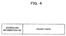
- the scheduling information transmitter unit 17 transmits scheduling information (SI)(a transmission request for obtaining transmission permission from the base station 2), such as a transmission rate assignment request to the base station 2, to the base station 2 via the transmitter 14.
- SI scheduling information
- the scheduling information transmitter unit 17 generates a signal (data packet) in which uplink data (transmission user data) to the base station 2 is added to the scheduling information, and then transmits the generated data to the base station 2.
- the transmitter 14 functions as a transmitter means for transmitting a transmission request to the base station 2 in order to obtain ransmission permission from the base station 2; the scheduling information transmitter unit 17 functions as a data adding means for adding uplink data to the above transmission request.
- the receiver 20 which receives data packets sent from the mobile station 1 at radio frequencies, has necessary radio reception processing functions such as downconversion of the data packet to an intermediate frequency (IF) band or a baseband and demodulation processing by QPSK or 16-QAM of the data packet.
- the CRC and ACK/NACK evaluating unit 21 performs CRC on a baseband signal received from the receiver 20 to carry out ACK/NACK evaluation. More precisely, if the CRC reveals a normal result, the CRC and ACK/NACK evaluating unit 21 generates ACK; if the CRC reveals an abnormal result, the CRC and ACK/NACK evaluating unit 21 generates NACK.
- the SI separating unit 22 separates and extracts the scheduling information from the received baseband signal, and the scheduler 23 performs sending-out scheduling of downlink (destined to the mobile station 1) data packet.
- the scheduling is determined based on such information as the quality of a received data packet, the amount of buffer remaining, and priority.
- the transmitter 24, which transmits downlink transmission data packets by radio, has radio transmission processing functions such as modulation and spread of transmission data packets and upconversion of the data packets to radio frequencies.
- the mobile station (UE) 1 transmits a random access signal, including a signature (information identifying each mobile station 1), to the base station (BTS) 2 at initiation of data transmission.
- the random access signal is sent through a common channel as an uplink data packet (step S1).
- the base station 2 transmits a reply to the access signal to the mobile station 1 (step 2), whereby a communication path is established over the common channel between the mobile station 1 and the base station 2.
- the mobile station 1 Upon receipt of the above reply, the mobile station 1 generates a signal (data packet) in which scheduling information (transmission rate assignment request) is added to the uplink transmission user data, as already described referring to FIG. 4 , in order to request the base station 2 to establish a dedicated channel, and then transmits the generated signal to the base station 2 through the communication path established over the foregoing common channel (step S3).
- the base station 2 Upon receipt of the above transmission rate assignment request, the base station 2 evaluates whether or not the requestedrate can be assigned to the mobile station 1. If the assignment is available, a message to that effect is sent back to the mobile station 1 as a transmission rate assignment reply (step S4).
- a dedicated channel is established between the mobile station 1 and the base station 2, whereby the mobile station 1 is ready for transmitting an uplink data packet.
- the mobile station 1 then starts to send an uplink data packet at the assigned rate through the assigned dedicated channel (step S5). If the base station 2 decides that it is impossible to assign the requested rate, it is possible for the base station 2, for example, to assign the maximum rate which can be assigned to the mobile station 1 at that time.
- FIG. 5 is a block diagram showing a construction of a radio mobile station, which is a constituent of a mobile communication system according to a second example useful for understanding the present invention
- FIG. 6 is a block diagram showing a construction of a radio base station, which is a constituent of the same system.
- the mobile station 1 of FIG. 5 is also capable of accessing the base station 2 of FIG. 6 by radio for establishing communication therebetween.
- downlink communication, from the base station 2 to the mobile station 1 is performed, for example, based on the HSDPA scheme
- uplink communication, from the mobile station 1 to the base station 2 is performed, for example, based on the HSUPA scheme.
- the mobile station 1 of FIG. 5 differs from the mobile station 1 of FIG. 1 in that a signature generating unit 18 is added thereto.
- the base station 2 of FIG. 6 differs from the base station 2 of FIG. 2 in that a signature separating unit 25 is added thereto.
- the signature generating unit 18 of the mobile station 1 generates a signature (information identifying each mobile station 1) as physical layer information contained in a random access signal (a channel establishment request to the base station 2 for establishing an dedicated channel for transmitting scheduling information, which is a transmission request, therethrough) to be transmitted to the base station 2 through a common channel at the start of data transmission.
- a signal (data packet) in which uplink user data is added to the generated signature is transmitted by the transmitter 14.
- the signature generating unit 18 and the transmitter 14 serve as a transmitter means for transmitting the above channel establishment request and also as an uplink data adding means for adding uplink data to the channel establishment request.
- the signature generating unit 18 is not used (does not operate) in uplink data transmission other than a random access signal.
- the signature separating unit 25 of the base station 2 separates and extracts the above signature from the data packet received by the receiver 20. From this signature, a mobile station 1 which has transmitted the received data packet is identified, and the transmitter 24 sends back a reply to the random access signal to the identified mobile station 1.
- the mobile station (UE) 1 At execution of HSUPA, the mobile station (UE) 1 generates a signal (see FIG. 8 ) in which uplink data (userdata) is added to a random access signal including a signature at the start of data transmission, and then sends the generated signal to the base station (BTS) 2 through a common channel (step S11).
- the signature separating unit 25 Upon receipt of this signal on the base station 2, the signature separating unit 25 separates and extracts the signature, based on which a mobile station 1 which has transmitted the above random access signal is identified, and a reply to the random access signal is transmitted to the identified mobile station 1 (step S12).
- a communication path is established over a common channel between the mobile station 1 and the base station 2.
- the mobile station 1 upon receipt of the above reply, the mobile station 1 generates a signal (data packet) in which scheduling information (transmission rate assignment request) is added to the uplink transmission user data in order to request the base station 2 to establish (set) a dedicated channel, and then transmits the generated signal to the base station 2 through the common channel (step S13).
- the base station 2 sends back a transmission rate assignment reply to the mobile station 1 (step S14), and the mobile station 1 sends an uplink data packet at the rate assigned by the transmission rate assignment reply (step S15).
- uplink data (user data) is added also to a random access signal sent from the mobile station 1 to the base station 2, so that it is possible to further reduce delay until the initial transmission in comparison with the first example.
- a channel used in random access is normally a common channel, whose transmission rate is lower than that of dedicated channels, so that the amount of user data to be added is limited.
- further improvement in throughput is expected.
- uplink data is added to both the random access signal and the transmission rate request (scheduling information) in the present example
- uplink data may be added only to the random access signal. In this case, the time until the start of uplink data transmission can still be reduced in comparison with the prior art, so that improvement in throughput is expected.
- the base station 2 it is possible for the base station 2 to notify the mobile station 1 of ACK/NACK with respect to uplink packet transmission from the mobile station 1 together with permission/non-permission for the following uplink transmission (transmission rate assignment permission/non-permission). More precisely, as shown in FIG. 10 , the transmitter 24 is capable of generating a signal (data packet) in which transmission rate permission/non-permission information is added to ACK/NACK information to be transmitted to the mobile station 1 (step S14' of FIG. 9 ).
- the transmitter 24 functions as a reply information transmitter means for transmitting reply information (ACK/NACK), which indicates whether or not an uplink data packet has been normally received from the mobile station 1, to the mobile station 1.
- the scheduler 23 functions as a notification information adding means for adding transmission permission/non-permission information, in response to a transmission request from the mobile station 1, to the reply information. Note that the other procedures in FIG. 9 are the same as or similar to those of FIG. 7 .
- ACK/NACK and uplink transmission rate assignment permission/non-permission are conventionally defined to be performed in different radio channels.
- E-AGCH E-DCH Absolute Grant Channel
- E-RGCH E-DCH Relative Grant Channel
- the base station 2 monitors (measures) an uplink communication state based on the amount of uplink traffic and the amount of interference. If the traffic amount or the interference amount is below a specific amount (reference value), each mobile station 1 is notified to that effect, thereby making it possible for each mobile station 1 to perform uplink transmission without prior permission of the base station 2.
- the base station 2 monitors an uplink communication state based on the traffic amount and the interference amount (step S21), and evaluates whether or not the traffic amount and the interference amount are not greater than a specific amount (reference value) (step S22). If those amounts are not greater than the reference value, the base station 2 judges that the uplink communication state is good, and notifies each mobile station 1 that prior permission is not necessary before starting of data transmission (from Yes route of step S22 to step S23). If those amounts are greater than the reference value, the base station 2 judges that the uplink communication state is not good, and then notifies each mobile station 1 that prior permission is necessary before starting of data transmission (from No route of step S22 to step S24).
- a specific amount reference value
- the base station 2 selectively switches between a mode (first mode) in which uplink data transmission can be performed without prior permission and another mode (second mode) in which uplink data transmission can be performed only after prior permission given.
- first mode a mode in which uplink data transmission can be performed without prior permission
- second mode another mode in which uplink data transmission can be performed only after prior permission given.
- each mobile station 1 receives a notification of a mode in which the mobile station 1 can start data transmission without obtaining prior permission from the base station 2, and that the mobile station 1 starts uplink packet transmission without permission of the base station 2, there is a possibility that a collision happens between the uplink transmission (data packets) from more than one mobile station 1. In such a case, the collided data packets are discarded on the base station 2. At this time, the mobile station 1 normally performs retransmission after waiting a random period. This makes it possible to lower the possibility of a collision at the time of retransmission performed, but there is another possibility that delay until the retransmission is enlarged.
- the base station 2 requests the mobile stations 1 to retransmit the packets. More precisely, as shown in FIG. 12 , it is assumed that the mobile stations 1-1 and 1-2 simultaneously transmit uplink data (step S31), and that a collision occurs on the base station 2.
- each of the mobile stations 1-1 and 1-2 performs uplink data transmission using a frame format including a signature, as already described with reference to FIG. 8 .
- the base station 2 sends a retransmission request to the mobile stations 1-1 and 1-2 at different timings (steps S32 and S33). This makes the mobile stations 1-1 and 1-2 transmit uplink data at different timings (steps S34 and S35).
- the foregoing operation is realized on the base station 2 by the scheduler 23 which functions as an uplink data collision monitoring means and the transmitter 24 which functions as a retransmission timing notifying means.
- the scheduler 23 as an uplink data collision monitoring means, monitors whether or not a collision occurs between uplink data transmission from two or more mobile stations 1 while the base station 2 is operating in the foregoing first mode. If a collision is detected by the uplink data collision monitoring means, the transmitter 24, as a retransmission timing notifying means, notifies the mobile stations that have transmitted the collided uplink data of timings for retransmitting the uplink data.
- the base station 2 While the base station 2 is waiting for data retransmission from the mobile stations 1-1 and 1-2, it is preferable that the base station 2 broadcast a busy signal to prevent other mobile stations from transmitting data. More specifically, as shown in FIG. 13 , when the base station 2 sends retransmission requests to the mobile stations 1-1 and 1-2 due to a collision which has occurred between the uplink transmission data packets of the mobile stations 1-1 and 1-2 (steps S32 and S33), the base station 2 broadcasts a busy signal through, for example, a common channel until retransmission from the mobile stations 1-1 and 1-2 (steps S34 and S35) is performed (or during a period in which retransmission is expected)(step S36).
- the base station 2 functions as a busy state informing means which informs each mobile station 1 within its cell of a busy state during a time period in which uplink data retransmission is expected from the relevant mobile stations 1 based on a notification of retransmission timing sent by the transmitter 24 as the retransmission timing notifying means.
- This function may be also given to the scheduler 23.
- step S37 While receiving the busy signal, another mobile station 1-3 refrains from uplink data transmission. After transmission of the busy signal from the base station 2 is ended, so that the busy signal is no longer received, the mobile station 1-3 starts uplink data transmission (step S37). This arrangement makes it possible to further lower the possibility of a collision of uplink transmission data packets.
- the length of data packets transmitted from the mobile stations 1-1, 1-2, and 1-3 (hereinafter will be called the "mobile station 1" when no distinction is made thereamong) and the base station 2 are preferably fixed. This makes it easy for the mobile station 1 to recognize with which timing retransmission should be performed when a collision of uplink data transmission happens on the base station 2.
- a data packet transmitted from the mobile station 1 has a user identification portion 5 identifying each user and a data portion 6 which is a message body. That is, the mobile station 1 has a function of an uplink data generating means which generates an uplink data packet having a user identification portion 5 identifying each mobile station 1 and a data portion 6 which is a message body, and also a function of an uplink data transmitter means which transmits the uplink data generated by the uplink data generating means to the base station 2. These functions are realized as one of the functions of the transmitter 14. In this case, the mobile station 1 is capable of performing stronger error correction processing to the user identification portion 5 than to the data portion 6.
- the user identification portion 5 can be separated into small divisions in the time axis direction, thereby being time-division multiplexed (TDM), as shown in FIG. 15 , or it can be separated in the frequency direction, thereby being orthogonal frequency-division multiplexed (OFDM), as shown in FIG. 16 , or it can be code-division multiplexed (CDM).
- TDM time-division multiplexed
- OFDM orthogonal frequency-division multiplexed
- CDM code-division multiplexed
- the base station 2 can identify the mobile stations 1 (users) based on information of the user identification portions 5, and that information of one of the data portions 6 is normally decoded, a description will be made hereinbelow of a method which makes it possible to evaluate which user (mobile station 1) the decoded data portion 6 corresponds to.
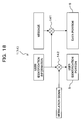
- the mobile station 1 encodes ⁇ performs multiplication by a multiplier (encoding means) 141 or an exclusive OR operation ⁇ a message to be stored in a data portion 6 using information (user identification information) of a user identification portion 5, and the encoded information is stored in the data portion 6.
- the user identification portion 5 stores a signal obtained by multiplying the above user identification information and the modulation signal together by means of a multiplier 142. This method makes it possible to make the user identification information contained (superposed) in the data portion 6 without significantly reducing the data amount in the data portion 6.
- the base station 2 includes: a data portion separating unit 26 which separates the user identification portion 5 and the data portion 6 from an output (an uplink data packet received) of the receiver (receiver means) 20; and a multiplier 27 which multiplies information of the user identification portion 5 and information of the data portion 6, separated by the data portion separating unit 26, together, to decode (reproduce) information of the data portion 6 (message body).
- a data portion separating unit 26 which separates the user identification portion 5 and the data portion 6 from an output (an uplink data packet received) of the receiver (receiver means) 20
- a multiplier 27 which multiplies information of the user identification portion 5 and information of the data portion 6, separated by the data portion separating unit 26, together, to decode (reproduce) information of the data portion 6 (message body).
- like reference numbers and characters designate similar parts or elements throughout several views of the embodiment, unless otherwise described.
- the base station 2 decodes the user identification portion 5 prior to the data portion 6, and using the decoded information, the base station 2 decodes information of the data portion 6. Accordingly, at a collision of data packets from different mobile stations 1, when information of the user identification portions 5 is correctly decoded, so that the mobile stations (users) 1 are identified, and also when information of one of the data portions 6 is correctly decoded, it is possible to decide which user (mobile station 1) the decoded data portion 6 corresponds to. As a result, it is possible to identify a mobile station 1 to which the above-mentioned retransmission request and ACK/NACK are to be transmitted.
- the mobile station 1 on the mobile station 1 (transmitter 14), user identification information, as it is, is contained (inserted) in a data portion 6 as a part thereof. That is, in this case, the transmitter 14 functions as an inserting means for inserting information of the user identification portion 5 into the data portion 6. This makes it possible to easily take out user identification information by decoding the information of the user identification portion 5 from the data portion 6 on the receiver end (base station 2).
- the transmitter 14 functions as an inserting means for inserting information of the user identification portion 5 into the data portion 6.
- the base station 2 includes, as well as the data portion separating unit 26 already described: a user identification information separating unit 28 which separates user identification information from the data portion 6 that has been separated by the data portion separating unit 26; and a comparing unit 29 which compares user identification information separated by the user identification information separating unit 28 with user identification information separated by the data portion separating unit 26.
- the data portion separating unit 26 separates the user identification portion 5 and the data portion 6 from an output (uplink data packet received) of the receiver (receiver means) 20, and the user identification information separating unit 28 further separates user identification information contained in the data portion 6, and the comparing unit 29 compares the user identification information separated by data portion separating unit 28 with the user identification information separated by the user identification information separating unit 26. Based on the comparison result (match/mismatch), the base station 2 is capable of deciding from which user (mobile station 1) the data portion 6 has been transmitted. As a result, a mobile station 1 to which the aforementioned retransmission request and ACK/NACK are to be transmitted is identified.
- the base station 2 transmits ACK to the mobile station 1.
- the base station 2 transmits NACK to the mobile station 1.
- the base station 2 transmits ACK to the mobile station 1 because the user can be identified based on the user identification information contained in the data portion 6.
- FIG. 22 shows an operation of the base station 2 in which the method described in the above section (C6. 1) is employed;
- FIG. 23 shows an operation of the base station 2 in which the method described in the above section (C6. 2) is employed.
- the base station 2 decodes a user identification portion 5 (step S41), and then decodes the data portion 6 (step S42).
- the CRC and ACK/NACK evaluating unit 21 performs CRC (step S43). If the CRC reveals an "OK" result (a correct decoding result has been obtained), the base station 2 generates ACK (step S44), and if the check reveals a "NG" result (a correct decoding result has not been obtained), the base station 2 generates NACK (step S45).
- the scheduler 23 evaluates whether or not scheduling information (permission for the following data transmission) to be transmitted to the mobile station 1 exists (step S46). If such scheduling information to be transmitted is present, the scheduling information is transmitted to the mobile station 1 together with the above ACK or NACK (from Yes route of step S46 to step S47), and if the scheduling information to be transmitted is not present, the above ACK or NACK is transmitted to the mobile station 1 as it is (from No route of step S46 to step S48).
- the base station 2 transmits permission for the following data transmission, together with ACK, to the mobile station 1 that has been identified based on the decoded user identification information. If a user identification portion 5 is correctly decoded but a data portion 6 is not correctly decoded, the base station 2 transmits permission for the following data transmission, together with NACK, to the mobile station 1 that has been identified based on the decoded user identification information.
- the base station 2 of the present example realizes a function of a reply and transmission permission transmitter means which transmits, if the user identification portion 5 and the data portion 6 are correctly decoded by the scheduler 23 and the transmitter 24, permission for the following uplink data transmission, together with reply information ACK indicating normal reception, to a mobile station 1 identified by information of the user identification portion 5, and which reply and transmission permission transmitter means transmits, if the user identification portion 5 is correctly decoded and the data portion 6 is not correctly decoded, permission for the following uplink data transmission, together with reply information NACK indicating abnormal reception, to a mobile station 1 identified by information of the user identification portion 5.
- the mobile station 1 transmits a data packet in which user identification information is inserted in a data portion 6 thereof
- the data portion separating unit 26 and the user identification information separating unit 28 (see FIG. 21 ) of the base station 2 separate, as shown in FIG. 23 , a user identification portion 5 and a data portion 6 of the received data packet (step S51), and the user identification information is decoded (step S52), and the CRC and ACK/NACK evaluating unit 21 performs CRC (step S53).
- the i -th user identification information, and user identification information contained in the data portion 6 are compared by the comparing unit 29, to evaluate if they match up (step S54 and step S55). If the two user identification information items match up, the base station 2 (CRC and ACK/NACK evaluating unit 21) generates ACK as a reply to the mobile station 1 (from Yes route of step S55 to step S56), and if the two do not match up, the base station 2 generates NACK (from NO route of step S55 to step S57).
- the scheduler 23 evaluates whether or not scheduling information (permission for the following data transmission) to be transmitted to the mobile station 1 exists (step S58). If the scheduling information to be transmitted is present, the scheduling information is sent to the mobile station 1 together with the ACK or NACK (from Yes route of step S58 to step S58a). If the scheduling information to be transmitted is not present, the above ACK or NACK is transmitted to the mobile station 1 as it is (from No route of step S58 to step S58b).
- the scheduler 23 and the transmitter 24 realize a function of a reply and transmission permission transmitter means, which transmits, if the data portion 6 is correctly decoded, permission for the following data transmission to the mobile station 1 identified based on the decoded information (user identification information contained in the data portion 6), together with reply information ACK indicating normal reception, and which transmits, if the user identification portion 5 is correctly decoded but the data portion 6 is not correctly decoded, the permission for the following data transmission to the mobile station 1 identified by information of the user identification portion 5 , together with reply information NACK indicating abnormal reception.
- the mobile station 1 evaluates whether or not a transmission schedule (that is, a data packet to be transmitted) is present (step S61). If there is no transmission schedule, the processing ends (No route of step S61). On the other hand, if there is a transmission schedule, the following (new) data packet is taken out from the data queue 10 (step S62), and the data packet is transmitted from the transmitter 14. Here, the time value of the timer 13 is reset to "0" (step S63).
- the mobile station 1 evaluates whether or not downlink signaling (data packet) is received from the base station 2 (step S64). If the evaluation result is negative (No route of step S64), it is further evaluated whether of not the timer value of the timer 13 is below a specific value T (T is a real number not smaller than 0)(step S65). If the timer value is below the specific value T (Yes route of step S65), the timer value is incremented (step S66a), and then monitoring is kept continued thereafter, while the time value is incremented, until a downlink data packet is received from the base station 2.
- the mobile station 1 transmits a retransmission request to the base station 2 and resets the timer value of the timer 13 to "0" (from No route of step S65 to steps S67 and S63).
- step S66b the mobile station 1 evaluates whether the data packet received is ACK or NACK (step S66b). If it is NACK, the mobile station 1 sends a retransmission request to the base station 2 (step S67). If it is ACK, the mobile station 1 further evaluates whether or not the following data packet is present in the data queue 10 (step S68). If the following data packet exists, the mobile station 1 transmits the data packet (from Yes route of step S68 to step S62), and if the data packet does not exist, the mobile station 1 ends the processing (No route of step S68).
- the mobile station 1 transmits the following data with the timing of the scheduling information. If the scheduling information is not received, the mobile station 1 recommences the processing from transmission of a retransmission request. In contrast, if the data packet received form the base station 2 is NACK, and also if the scheduling information is received, the mobile station 1 transmits the following data with the timing of the scheduling information.
- the mobile station 1 If the mobile station 1 has not received scheduling information, or if the mobile station 1 has received nothing (DTX), the mobile station 1 recommences the processing from transmission of a retransmission request.
- DTX nothing
- the receiver 15 of the mobile station 1 has a function of a reply and transmission permission receiver means which receives scheduling information (permission for uplink data transmission) together with reply information (ACK/NACK) indicating normal reception or abnormal reception of uplink data from the base station 2.
- scheduling information permission for uplink data transmission
- ACK/NACK reply information
- the transmitter 14 of the mobile station 1 transmits the following uplink data packet in pursuance of the scheduling information.
- the transmitter 14 transmits an uplink data retransmission request to the base station 2 in pursuance of the scheduling information.
- T specific time period
- the transmitter 14 transmits an uplink data retransmission request to the base station 2.
- request to reply information sent to the mobile station (1), which reply information indicates whether or not the uplink data sent from the mobile station (1) has been normally received.
- Another embodiment of the invention may provide a communication method in a mobile communication system including at least one mobile station (1) and a base station (2), which performs radio communication with the mobile station (1), wherein the base station (2) is operable in a first mode in which the base station (2)'s permission is not necessary when the mobile station (1) transmits uplink data, and a second mode in which the base station (2)'s permission is necessary when the mobile station (1) transmits uplink data, the method comprising: at the base station (2), monitoring an uplink communication state between the base station (2) and the mobile station (1) (S21 and S22); operating in the first mode if the uplink communication state is of a specific or higher level of quality (S23); and operating in the second mode if the uplink communication state is of quality lower than the specific level (S24).
- the above method may further comprise, at the base station (2), monitoring, while operating in the first mode, whether or not a collision occurs in uplink data transmission from two or more mobile stations (1); and notifying each of the mobile station (1), if a collision occurs, of retransmission timing in the uplink data transmission (S32 and S33).
- This method may additionally comprise, at the base station (2), informing the two or more mobile stations (1) of a busy state during a specific period in which uplink data retransmission is expected based on the notification of the retransmission timing (S36).
- the above method may also comprise the step, at the mobile station (1), of performing the uplink data transmission using uplink data having a fixed data length.
- the uplink data may include: a user identification portion (5) identifying each mobile station (1); and a data portion (6) which is a message body.
- the user identification portion (5) is obtained by time-division multiplexing, or frequency-division multiplexing, or code-division multiplexing the user identification information of each of the two or more mobile stations (1).
- the method may further comprise, at the mobile station (1), encoding the data portion (6) based on information of the user identification portion (5), and/or inserting information of the user identification portion (5) into the data portion (6).
- the base station (2) may perform a step of performing a decoding process from the user identification portion (5), or performing a decoding process from the data portion (6).
- the method may further comprise, at the base station (2), transmitting, if the user identification portion (5) and the data portion (6) are correctly decoded, permission for the following uplink data transmission, together with reply information indicating a normal reception, to a mobile station (1) identified by information of the user identification portion (5) (S44 and S47); and transmitting, if the user identification portion (5) is correctly decoded but the data portion (6) is not correctly decoded, permission for the following uplink data transmission, together with reply information indicating an abnormal reception, to a mobile station (1) identified by information of the user identification portion (5) (S45 and S47).
- the above method may alternatively further comprise at the base station (2), transmitting, if the data portion (6) is correctly decoded, permission for the following uplink data transmission, together with reply information indicating a normal reception, to a mobile station (1) identified based on the decoded information (S56 and S58a); and transmitting, if the user identification portion (5) is correctly decoded but the data portion (6) is not correctly decoded, permission for the following uplink data transmission, together with reply information indicating an abnormal reception, to a mobile station (1) identified by information of the user identification portion (5) (S57 and S58b).
- the mobile station (1) may perform steps of: transmitting, if the data transmission permission is received from the base station (2) together with the reply information indicating a normal reception, the following uplink data to the base station (2) in pursuance of the uplink data transmission permission (S64, S66b, and S68); and transmitting, if the data transmission permission is received from the base station (2) together with the reply information indicating an abnormal reception, an uplink data retransmission request to the base station (2) in pursuance of the uplink data transmission permission (S64, S66b, and S67).
- the mobile station (1) may transmit an uplink data retransmission request to the base station (2), if downlink data is not received from the base station (2) within a specific period (S64, S65, and S67).
- Another embodiment of the invention may provide a system including at least one mobile station (1) and a base station (2), which performs radio communication with the mobile station (1), the mobile station (1) comprising: transmitter means (10, 11, and 14) which transmits a transmission request to the base station (2) for obtaining permission for data transmission or a channel establishment request to the base station (2) for establishing a channel in order to send the transmission request therethrough; and data adding means (17) which adds uplink data to the transmission request or to the channel establishment request.
- a further embodiment may provide a base station for a mobile communication system including at least one mobile station (1) and a base station (2), which performs radio communication with the mobile station (1), the base station (2) comprising: reply information transmitter means (21 and 24) which transmits reply information, indicating whether or not the uplink data sent from the mobile station (1) has been normally received, to the mobile station (1); and notification information adding means (23) which adds transmission permission/non-permission notification information, indicating whether or not data transmission is permitted in response to the transmission request, to the reply information to be sent to the mobile station (1).
- an embodiment may provide a base station for a mobile communication system including at least one mobile station (1) and a base station (2), which performs radio communication with the mobile station (1), wherein said mobile station (1) is operable in a first mode in which the base station (2) 's permission is not necessary when the mobile station (1) transmits uplink data, and a second mode in which the base station (2)'s permission is necessary when the mobile station (1) transmits uplink data, the base station comprising: uplink communication state monitoring means (231) which monitors an uplink communication state between the base station (2) and the mobile station (1); evaluating means (232) which evaluates whether or not the communication state monitored by the communication state monitoring means (231) is of a specific or higher level of quality; and mode selecting means (233) which selects the first mode as an operation mode if the evaluation result is positive, and which selects the second mode as an operation mode if the evaluation result is negative.
- the base station just mentioned may further comprise: data collision monitoring means (23) which monitors, while operating in the first mode, whether or not a collision occurs in uplink data transmission from two or more mobile stations (1); and retransmission timing notifying means (24) which notifies each of the mobile stations (1), if an occurrence of a collision is detected by said data collision monitoring means (23), of retransmission timing in the uplink data transmission.
- data collision monitoring means (23) which monitors, while operating in the first mode, whether or not a collision occurs in uplink data transmission from two or more mobile stations (1)
- retransmission timing notifying means (24) which notifies each of the mobile stations (1), if an occurrence of a collision is detected by said data collision monitoring means (23), of retransmission timing in the uplink data transmission.
- the base station may further comprise: busy state informing means (23) which informs the two or more mobile stations (1) of a busy state during a specific period in which uplink data retransmission is expected based on the notification of the retransmission timing made by said retransmission timing notifying means (24).
- the above-defined base station may also include, as a first form, receiver means (20) which receives uplink data including: a user identification portion (5) identifying each mobile station (1); and a data portion (6), which is a message body, the uplink data having been sent out from the mobile station (1) after being encoded using information of the user identification portion (5); and decoding means (26 and 27) which decodes the uplink data, received by said receiver means (20), from the user identification portion (5).
- receiver means (20) which receives uplink data including: a user identification portion (5) identifying each mobile station (1); and a data portion (6), which is a message body, the uplink data having been sent out from the mobile station (1) after being encoded using information of the user identification portion (5); and decoding means (26 and 27) which decodes the uplink data, received by said receiver means (20), from the user identification portion (5).
- the base station may include, as a second form, receiver means (20) which receives uplink data including: a user identification portion (5) identifying each mobile station (1); and a data portion (6), which is a message body, said uplink data having been sent out from the mobile station (1) after information of the user identification portion (5) is inserted in the data portion (6) thereof; and decoding means (26, 28, and 29) which decodes the uplink data, received by said receiver means (20), from the data portion (6).
- receiver means (20) which receives uplink data including: a user identification portion (5) identifying each mobile station (1); and a data portion (6), which is a message body, said uplink data having been sent out from the mobile station (1) after information of the user identification portion (5) is inserted in the data portion (6) thereof; and decoding means (26, 28, and 29) which decodes the uplink data, received by said receiver means (20), from the data portion (6).
- the base station of the first form may further comprise: a reply and transmission permission transmitter means (21) which transmits, if the user identification portion (5) and the data portion (6) are correctly decoded, permission for the following uplink data transmission, together with reply information indicating normal reception, to a mobile station (1) identified by information of the user identification portion (5).
- a reply and transmission permission transmitter means (21) which transmits, if the user identification portion (5) and the data portion (6) are correctly decoded, permission for the following uplink data transmission, together with reply information indicating normal reception, to a mobile station (1) identified by information of the user identification portion (5).
- the reply and transmission permission transmitter means (21) may transmit, if the user identification portion (5) is correctly decoded but the data portion (6) is not correctly decoded, permission for the following uplink data transmission, together with reply information indicating abnormal reception, to a mobile station (1) identified by information of the user identification portion (5).
- the base station of the second form may further comprise: a reply and transmission permission transmitter means (21) which transmits, if the data portion (6) is correctly decoded, permission for the following uplink data transmission, together with reply information indicating a normal reception, to a mobile station (1) identified based on the decoded information.
- a reply and transmission permission transmitter means (21) which transmits, if the data portion (6) is correctly decoded, permission for the following uplink data transmission, together with reply information indicating a normal reception, to a mobile station (1) identified based on the decoded information.
- this reply and transmission permission transmitter means (21) may transmit, if the user identification portion (5) is correctly decoded but the data portion (6) is not correctly decoded, permission for the following uplink data transmission, together with reply information indicating an abnormal reception, to a mobile station (1) identified by information of the user identification portion (5).
- Another embodiment of the invention may provide a mobile station for a mobile communication system including at least one mobile station (1) and a base station (2), which performs radio communication with the mobile station (1), in which mobile communication system the base station (2) notifies, if a collision occurs in uplink data transmission from two or more mobile stations (1), each of the mobile stations (1) of retransmission timing in the uplink data transmission, the mobile station comprising: uplink data generating means which generates uplink data including: a user identification portion (5) identifying each mobile station (1); and a data portion (6), which is a message body; and uplink data transmitter means (14) which transmits the uplink data generated by the uplink data generating means to the base station (2).
- the uplink data generating means may generate the uplink data as data having a fixed data length.
- the uplink data generating means may include encoding means (141) which encodes the data portion (6) based on information of the user identification portion (5).
- the uplink data generating means may include inserting means (14) which inserts information of the user identification portion (5) into the data portion (6).
- the mobile station may further comprise: reply and transmission permission receiver means (15 and 16) which receives permission for uplink data transmission together with reply information indicating normal or abnormal reception of the uplink data from the base station (2), wherein said uplink transmitter means (10, 11, and 14) transmits, if said reply and transmission permission receiver means (15 and 16) receives the data transmission permission together with the reply information indicating a normal reception, the following uplink data to the base station (2) in pursuance of the uplink data transmission permission, and wherein said uplink data transmitter means (10, 11, and 14) transmits, if said reply and transmission permission receiver means (15 and 16) receives the data transmission permission together with the reply information indicating an abnormal reception, an uplink data retransmission request to the base station (2) in pursuance of the uplink data transmission permission.
- reply and transmission permission receiver means (15 and 16) which receives permission for uplink data transmission together with reply information indicating normal or abnormal reception of the uplink data from the base station (2), wherein said uplink transmitter means (10, 11, and 14) transmits, if said reply and transmission permission receiver
- the uplink data transmitter means (10, 11, and 14) may transmit an uplink data retransmission request to the base station (2), if downlink data is not received from the base station (2) within a specific period.
Description
-
- (1) Field of the Invention:
- The present invention relates to a communication method in a mobile communication system and a mobile station and a base station in the same system. The invention relates particularly to a technique suitable to improve the throughput of uplink data communication from the mobile station to the base station.
- (2) Description of Related Art:
- In the current 3GPP (3rd Generation Partnership Project), standardization of W-CDMA (Wideband-Code Division Multiple Access), which is one of the schemes of the third-generation mobile communication system, is in progress. One of the themes of the standardization is
- the HSDPA (High Speed Downlink Packet Access) scheme which provides a great-capacity high-speed packet data transfer (about 14 Mbps at maximum) in the downlink direction from a base station to a mobile station. Further, the HSUPA (High Speed Uplink Packet Access) scheme, which can be regarded as HSDPA in the uplink direction from a mobile station to a base station, is under investigation (see, for example, the following non-patent document 1).
- In such high-speed data transmission, data transmission scheduling for efficient sending-out of data packet is important. In HSUPA, scheduling is determined based on such information as reception quality, the amount of buffer remaining, priority, and so on. These information items are notified from a mobile station to a base station as Scheduling Information (SI) in form of an uplink transmission request prior to uplink transmission.
- [Patent Document 1] United States Patent Application Publication Number
US 5 673 259 A - [Patent Document 2] European Patent Application
Publication Number EP 0 998 158 A2 - [Non-patent Document 1] 3rd Generation Partnership Project (3GPP) ; Technical Specification Group Radio Access Network; "TS 25.309 V6.2.0 (2005-03) FDD Enhanced Uplink Overall Description Stage 2 (Release 6)"
- In the present 3GPP specification, communication execution by HSUPA is performed after establishment of dedicated radio channels, and as procedures from call generation to call setting and HSUPA application, known procedures applied. Accordingly, delay occurs between a data transmission request on a terminal and actual data transmission.
- For example, as shown in
FIG. 25 , a mobile station (UE: User Equipment) 100 sends an access request to a base station (BTS: Base Transceiver Station) 200 (step S100) by a random access method. Upon receipt of a reply to the access request from the base station 200 (step S200), the mobile station 100 sends a dedicated radio channel establishment request to the base station 200 (step S300). When a reply to the channel establishment request is received by the mobile station 100 (step 400), the mobile station 100 sends a transmission rate request to the base station 200 (step S500). When a rate is assigned by the base station 200 (step S600) in response to the transmission rate request, the mobile station 100 eventually starts data transmission (steps S700 and S900). Here, when the data transmitted is normally received by the base station 200, ACK is sent back to the mobile station 100, and when the data transmitted is not received normally, NACK is sent back to the mobile station 100 (step S800). Upon receipt of NACK, the mobile station 100 performs data retransmission. - Under a condition where the data rate is low, delay caused by such negotiation prior to actual uplink data transmission is inconspicuous, but as the data rate increases, the delay becomes a considerable problem. In addition, for realization of "Always on" by radio, it is preferable that connection delay be as small as possible.
-
Patent Document 1 discloses a digital communication system including a dedicated channel for communicating a data packet between a communicating transceiver and a base station and a processor for switching from a random access channel to the dedicated channel when the bandwidth demand exceeds a first threshold, and for switching from the dedicated channel to the random access channel when the bandwidth demand drops below a second threshold. -
Patent Document 2 discloses a communication state improving method in a mobile communication system in which a plurality of mobile units generate communication channel setting requests to a base station by using a common channel, and the retransmission count of a communication channel setting request in a service area of the base station is measured. - With the foregoing problems in view, it is an object of the present invention to suppress delay caused by negotiation prior to actual uplink data transmission as much as possible, thereby realizing efficient uplink data transmission, that is, an improved throughput of uplink communication.
- In order to accomplish the above object, according to the present invention, the following communication method, mobile station, and base station are provided.
- (1) As a generic feature, there is provided a mobile communication system comprising at least one mobile station and a base station, which performs radio communication between the mobile station and the base station, characterized by the base station comprising: a monitor configured to monitor an uplink communication state between the mobile station and the base station; and a transmitter configured to transmit information indicating whether or not the mobile station is required to receive from the base station a permission for transmitting uplink data to the base station, the information being based on the monitored uplink communication state; and by the mobile station comprising: a receiver configured to receive the information transmitted from the base station; and a controller configured to control the transmission of the uplink data based on whether or not the information received by the receiver indicates that the mobile station requires the permission for transmitting uplink data to the base station.
- (2) As another generic feature, there is provided a communication method in a mobile communication system including at least one mobile station and a base station, which performs radio communication between the mobile station and the base station, the communication method characterized by: monitoring, at the base station, an uplink communication state between the mobile station and the base station; and transmitting, by the base station, information indicating whether or not the mobile station is required to receive from the base station a permission for transmitting uplink data to the base station, the information being based on the monitored uplink communication state receiving, by the mobile station, the information transmitted from the base station; and controlling, at the mobile station, the transmission of the uplink data based on whether or not the received information indicates that the mobile station requires the permission for transmitting uplink data to the base station.
- (3) As yet another generic feature, there is provided a base station for a mobile communication system including at least one mobile station, which performs radio communication between the mobile station and the base station, the base station characterized by: a monitor configured to monitor an uplink communication state between the mobile station and the base station; and a transmitter configured to transmit information indicating whether or not the mobile station is required to receive from the base station a permission for transmitting uplink data to the base station, the information being based on the monitored uplink communication state, the information allowing the mobile station to control the transmission of the uplink data based on whether or not the information indicates that the mobile station requires the permission for transmitting uplink data to the base station.
- (4) As a further generic feature, there is provided a mobile station for a mobile communication system including a base station, which performs radio communication between the mobile station and the base station, the mobile station characterized by: a receiver configured to receive information indicating whether or not the mobile station is required to receive from the base station a permission for transmitting uplink data to the base station, the information being based on an uplink communication state between the mobile station and the base station; and a controller configured to control the transmission of the uplink data based on whether or not the information received by the receiver indicates that the mobile station requires the permission for transmitting uplink data to the base station.
- (5) As a preferred feature the controller in the mobile station is further configured to select one of a first mode and a second mode in accordance with the received information, the first mode in which the permission is not required to transmit the uplink data, and the second mode in which the permission is required to transmit the uplink data.
- (6) As another preferred feature, the mobile station further comprises: a transmitter configured to transmit the uplink data including information for user identification to the base station.
- The above-described invention realizes efficient data transmission. Delay at the time of call setting is expected to be reduced and improvement in throughput is also expected.
- Other objects and further features of the present invention will be apparent from the following detailed description when read in conjunction with the accompanying drawings.
-
-
FIG. 1 is a block diagram showing a construction of a radio mobile station, which is a constituent of a mobile communication system according to a first example useful for understanding the present invention; -
FIG. 2 is a block diagram showing a construction of a radio base station, which is a constituent of the mobile communication system according to the first example; -
FIG. 3 is a sequence diagram for describing an operation (uplink communication method) of a mobile communication system of the first example; -
FIG. 4 is a diagram showing a frame construction of an uplink transmission request according to the first example; -
FIG. 5 is a block diagram showing a construction of a radio mobile station, which is a constituent of a mobile communication system according to a second example useful for understanding the present invention; -
FIG. 6 is a block diagram showing a construction of a radio base station, which is a constituent of the mobile communication system according to the second example; -
FIG. 7 is a sequence diagram for describing an operation (uplink communication method) of a mobile communication system of the second example; -
FIG. 8 is a diagram showing a frame construction of a random access signal according to the second example; -
FIG. 9 is a sequence diagram for describing an operation (uplink communication method) of a mobile communication system according to a modified example of the second example; -
FIG. 10 is a diagram showing a frame construction of a downlink signal according to the second example; -
FIG. 11 is a flowchart for describing an operation of a base station in a mobile communication system according to an embodiment of the present invention; -
FIG. 12 is a sequence diagram for describing an uplink communication method according to a first modified example of the embodiment; -
FIG. 13 is a sequence diagram for describing an uplink communication method according to a second modified example of the embodiment; -
FIG. 14 is a diagram showing a data packet construction according to a fourth modified example of the embodiment; -
FIG. 15 is a diagram showing a construction of the user identification portion (time-division multiplexed) illustrated inFIG. 14 ; -
FIG. 16 is a diagram showing a construction of the user identification portion (frequency-division multiplexed) illustrated inFIG. 14 ; -
FIG. 17 is a diagram showing a construction of the user identification portion (code-division multiplexed) illustrated inFIG. 14 ; -
FIG. 18 is a diagram for describing a method for encoding a data portion on a mobile station according to a first mode of a sixth modified example of the embodiment; -
FIG. 19 is a block diagram showing a construction of a base station corresponding to the mobile station ofFIG. 18 ; -
FIG. 20 is a diagram for describing a method for encoding a data portion on a mobile station according to a second mode of the sixth modified example of the embodiment; -
FIG. 21 is a block diagram showing a construction of a base station corresponding the mobile station ofFIG. 20 ; -
FIG. 22 is a flowchart for describing an operation of the base station ofFIG. 19 ; -
FIG. 23 is a flowchart for describing an operation of the base station ofFIG. 21 ; -
FIG. 24 is a flowchart for describing an operation of a mobile station corresponding to a base station shown inFIG. 19 orFIG. 21 ; and -
FIG. 25 is a sequence diagram for describing conventional procedures for uplink packet transmission. -
FIG. 1 is a block diagram showing a construction of a radio mobile station, which is a constituent of a mobile communication system according to a first example useful for understanding the present invention;FIG. 2 is a block diagram showing a construction of a radio base station, which is a constituent of the same system. The radio mobile station (hereinafter will be simply called the "mobile station") 1 inFIG. 1 accesses the radio base station (hereinafter will be simply called the "base station") 2 inFIG. 2 by radio for establishing communication therebetween. Here,
downlink communication, from thebase station 2 to themobile station 1, is performed, for example, based on the HSDPA scheme, and uplink communication, from themobile station 1 to thebase station 2, is performed, for example, based on the HSUPA scheme. The above mobile communication system includes one or moremobile stations 1 ofFIG. 1 and one ormore base stations 2 ofFIG. 2 . - As shown in
FIG. 1 , with attention focused on its important part, themobile station 1 includes : adata queue 10; an ACK/NACK/DTX evaluating unit 11; aretransmission buffer 12; atimer 13; atransmitter 14; areceiver 15; ademodulator unit 16; and a schedulinginformation transmitter unit 17. As shown inFIG. 2 , with attention focused on its important part, thebase station 2 includes : areceiver 20; a CRC and ACK/NACK evaluating unit 21; anSI separating unit 22; ascheduler 23; atransmitter 24. - Here, in the
mobile station 1 ofFIG. 1 , thedata queue 10 holds data packets (uplink signals) waiting for transmission; the ACK/NACK/DTX evaluating unit (hereinafter will be also simply called the "evaluating unit") 11 evaluates if ACK or NACK has been received from thebase station 2 as a result of data demodulation by thedemodulator unit 16, or if no data packet (downlink signal) is received from the base station 2 (DTX) . Upon confirmation of receipt of ACK, the evaluatingunit 11 takes out a data packet waiting for transmission from thedata queue 10 and sends the data packet to thetransmitter 14. Upon confirmation of receipt of NACK, the evaluatingunit 11 takes out an object data packet, which has already been transmitted, from theretransmission buffer 12, and then sends the object data packet to thetransmitter 14. - The
timer 13 measures a predetermined time period elapsed after the data packet is transferred to thetransmitter 14, that is, after the data packet is sent to thebase station 2. If the evaluatingunit 11 does not confirm the receipt of ACK or NACK even after elapse of the predetermined time, thetimer 13 gives the evaluating unit 11 a trigger which makes the evaluatingunit 11 end a standby mode for receiving ACK or NACK and makes the transmission processing proceed to the next step. - The
transmitter 14, which transmits uplink transmission data packets from the evaluatingunit 11 to thebase station 2 by radio, has necessary radio transmission processing functions such as modulation and spread of transmission data packets, and upconversion of the data packets to radio frequencies. - The
receiver 15, which receives data packets sent from thebase station 2 by radio at radio frequencies, has necessary radio reception processing functions such as downconversion of the data packets to an intermediate frequency (IF) band and a baseband. Thedemodulator unit 16 performs necessary demodulation processing to the baseband signal from thereceiver 15, the modulation processing corresponding to the transmission modulation scheme {e.g., QPSK (Quadrature Phase Shift Keying) or 16-QAM (Quadrature Amplitude Modulation)} used on thebase station 2. - The scheduling
information transmitter unit 17 transmits scheduling information (SI)(a transmission request for obtaining transmission permission from the base station 2), such as a transmission rate assignment request to thebase station 2, to thebase station 2 via thetransmitter 14. In the present example, as shown inFIG. 4 , the schedulinginformation transmitter unit 17 generates a signal (data packet) in which uplink data (transmission user data) to thebase station 2 is added to the scheduling information, and then transmits the generated data to thebase station 2. In other words, thetransmitter 14 functions as a transmitter means for transmitting a transmission request to thebase station 2 in order to obtain ransmission permission from thebase station 2; the schedulinginformation transmitter unit 17 functions as a data adding means for adding uplink data to the above transmission request. - On the other hand, in the
base station 2 ofFIG. 2 , thereceiver 20, which receives data packets sent from themobile station 1 at radio frequencies, has necessary radio reception processing functions such as downconversion of the data packet to an intermediate frequency (IF) band or a baseband and demodulation processing by QPSK or 16-QAM of the data packet. The CRC and ACK/NACK evaluating unit 21 performs CRC on a baseband signal received from thereceiver 20 to carry out ACK/NACK evaluation. More precisely, if the CRC reveals a normal result, the CRC and ACK/NACK evaluating unit 21 generates ACK; if the CRC reveals an abnormal result, the CRC and ACK/NACK evaluating unit 21 generates NACK. - The
SI separating unit 22 separates and extracts the scheduling information from the received baseband signal, and thescheduler 23 performs sending-out scheduling of downlink (destined to the mobile station 1) data packet. The scheduling is determined based on such information as the quality of a received data packet, the amount of buffer remaining, and priority. - The
transmitter 24, which transmits downlink transmission data packets by radio, has radio transmission processing functions such as modulation and spread of transmission data packets and upconversion of the data packets to radio frequencies. - Now, referring to
FIG. 3 , a description will made hereinbelow of an operation of a mobile communication system of the present example with the above-described construction. - At execution of HSUPA, the mobile station (UE) 1 transmits a random access signal, including a signature (information identifying each mobile station 1), to the base station (BTS) 2 at initiation of data transmission. The random access signal is sent through a common channel as an uplink data packet (step S1). When receiving the random access signal, the
base station 2 transmits a reply to the access signal to the mobile station 1 (step 2), whereby a communication path is established over the common channel between themobile station 1 and thebase station 2. - Upon receipt of the above reply, the
mobile station 1 generates a signal (data packet) in which scheduling information (transmission rate assignment request) is added to the uplink transmission user data, as already described referring toFIG. 4 , in order to request thebase station 2 to establish a dedicated channel, and then transmits the generated signal to thebase station 2 through the communication path established over the foregoing common channel (step S3). Upon receipt of the above transmission rate assignment request, thebase station 2 evaluates whether or not the requestedrate can be assigned to themobile station 1. If the assignment is available, a message to that effect is sent back to themobile station 1 as a transmission rate assignment reply (step S4). - When the
mobile station 1 receives the transmission rate assignment reply from thebase station 2, a dedicated channel is established between themobile station 1 and thebase station 2, whereby themobile station 1 is ready for transmitting an uplink data packet. Themobile station 1 then starts to send an uplink data packet at the assigned rate through the assigned dedicated channel (step S5). If thebase station 2 decides that it is impossible to assign the requested rate, it is possible for thebase station 2, for example, to assign the maximum rate which can be assigned to themobile station 1 at that time. - As described so far, according to the system of the present example, since an uplink data packet is added (superimposed) to a transmission rate request sent from the
mobile station 1 to thebase station 2, it is possible to reduce the procedures in need for starting data transmission, in comparison with the prior art. This also makes it possible to shorten a call-setting time, thereby reducing delay until the start of data transmission. In this case, the amount of data to be added depends on the transmission rate of the dedicated channel, so that the transmission rate is kept lower than that of normal uplink packet transmission. However, since the time until the start of data transmission is shortened, throughput is expected to be improved. -
FIG. 5 is a block diagram showing a construction of a radio mobile station, which is a constituent of a mobile communication system according to a second example useful for understanding the present invention;FIG. 6 is a block diagram showing a construction of a radio base station, which is a constituent of the same system. Themobile station 1 ofFIG. 5 is also capable of accessing thebase station 2 ofFIG. 6 by radio for establishing communication therebetween. In this case, also, downlink communication, from thebase station 2 to themobile station 1, is performed, for example, based on the HSDPA scheme, and uplink communication, from themobile station 1 to thebase station 2, is performed, for example, based on the HSUPA scheme. - The
mobile station 1 ofFIG. 5 differs from themobile station 1 ofFIG. 1 in that asignature generating unit 18 is added thereto. Thebase station 2 ofFIG. 6 differs from thebase station 2 ofFIG. 2 in that asignature separating unit 25 is added thereto. - Here, the
signature generating unit 18 of themobile station 1 generates a signature (information identifying each mobile station 1) as physical layer information contained in a random access signal (a channel establishment request to thebase station 2 for establishing an dedicated channel for transmitting scheduling information, which is a transmission request, therethrough) to be transmitted to thebase station 2 through a common channel at the start of data transmission. In the present example, as shown inFIG. 8 , for example, a signal (data packet) in which uplink user data is added to the generated signature is transmitted by thetransmitter 14. - In other words, the
signature generating unit 18 and thetransmitter 14 serve as a transmitter means for transmitting the above channel establishment request and also as an uplink data adding means for adding uplink data to the channel establishment request. Here, thesignature generating unit 18 is not used (does not operate) in uplink data transmission other than a random access signal. - The
signature separating unit 25 of thebase station 2 separates and extracts the above signature from the data packet received by thereceiver 20. From this signature, amobile station 1 which has transmitted the received data packet is identified, and thetransmitter 24 sends back a reply to the random access signal to the identifiedmobile station 1. - Now, referring to
FIG. 7 , a description will be made hereinbelow of an operation of a mobile communication system of the present example with the above-described construction. At execution of HSUPA, the mobile station (UE) 1 generates a signal (seeFIG. 8 ) in which uplink data (userdata) is added to a random access signal including a signature at the start of data transmission, and then sends the generated signal to the base station (BTS) 2 through a common channel (step S11). Upon receipt of this signal on thebase station 2, thesignature separating unit 25 separates and extracts the signature, based on which amobile station 1 which has transmitted the above random access signal is identified, and a reply to the random access signal is transmitted to the identified mobile station 1 (step S12). As a result, a communication path is established over a common channel between themobile station 1 and thebase station 2. - After that, as in the case of
FIG. 3 , upon receipt of the above reply, themobile station 1 generates a signal (data packet) in which scheduling information (transmission rate assignment request) is added to the uplink transmission user data in order to request thebase station 2 to establish (set) a dedicated channel, and then transmits the generated signal to thebase station 2 through the common channel (step S13). Thebase station 2 sends back a transmission rate assignment reply to the mobile station 1 (step S14), and themobile station 1 sends an uplink data packet at the rate assigned by the transmission rate assignment reply (step S15). - Inthisexample, as described above, uplink data (user data) is added also to a random access signal sent from the
mobile station 1 to thebase station 2, so that it is possible to further reduce delay until the initial transmission in comparison with the first example. Here, a channel used in random access is normally a common channel, whose transmission rate is lower than that of dedicated channels, so that the amount of user data to be added is limited. However, since the delay until the initial transmission is more reduced in comparison with the first example, further improvement in throughput is expected. - Here, although uplink data is added to both the random access signal and the transmission rate request (scheduling information) in the present example, uplink data may be added only to the random access signal. In this case, the time until the start of uplink data transmission can still be reduced in comparison with the prior art, so that improvement in throughput is expected.
- In the foregoing second example, it is possible for the
base station 2 to notify themobile station 1 of ACK/NACK with respect to uplink packet transmission from themobile station 1 together with permission/non-permission for the following uplink transmission (transmission rate assignment permission/non-permission). More precisely, as shown inFIG. 10 , thetransmitter 24 is capable of generating a signal (data packet) in which transmission rate permission/non-permission information is added to ACK/NACK information to be transmitted to the mobile station 1 (step S14' ofFIG. 9 ). - In other words, the
transmitter 24 functions as a reply information transmitter means for transmitting reply information (ACK/NACK), which indicates whether or not an uplink data packet has been normally received from themobile station 1, to themobile station 1. Thescheduler 23 functions as a notification information adding means for adding transmission permission/non-permission information, in response to a transmission request from themobile station 1, to the reply information. Note that the other procedures inFIG. 9 are the same as or similar to those ofFIG. 7 . - This arrangement will simplify the procedures of downlink transmission. More precisely, ACK/NACK and uplink transmission rate assignment permission/non-permission are conventionally defined to be performed in different radio channels. For example, in HSUPA, ACK/NACK is transmitted through an E-HICH {E-DCH (Enhanced-Dedicated CHannel) HARQ (Hybrid Automatic Repeat reQuest) Acknowledgement Indicator Channel}; assignment permission/non-permission is transmitted through an E-AGCH (E-DCH Absolute Grant Channel) or an E-RGCH (E-DCH Relative Grant Channel). In contrast, in the present example, ACK/NACK and transmission rate permission/non-permission can be notified to the
mobile station 1 through the same channel at the same time. Accordingly, the time until the start of data transmission is reduced, thereby improving throughput. - In the above examples, the
base station 2 monitors (measures) an uplink communication state based on the amount of uplink traffic and the amount of interference. If the traffic amount or the interference amount is below a specific amount (reference value), eachmobile station 1 is notified to that effect, thereby making it possible for eachmobile station 1 to perform uplink transmission without prior permission of thebase station 2. - That is, as shown in
FIG. 11 , thebase station 2 monitors an uplink communication state based on the traffic amount and the interference amount (step S21), and evaluates whether or not the traffic amount and the interference amount are not greater than a specific amount (reference value) (step S22). If those amounts are not greater than the reference value, thebase station 2 judges that the uplink communication state is good, and notifies eachmobile station 1 that prior permission is not necessary before starting of data transmission (from Yes route of step S22 to step S23). If those amounts are greater than the reference value, thebase station 2 judges that the uplink communication state is not good, and then notifies eachmobile station 1 that prior permission is necessary before starting of data transmission (from No route of step S22 to step S24). - In other words, the
base station 2 selectively switches between a mode (first mode) in which uplink data transmission can be performed without prior permission and another mode (second mode) in which uplink data transmission can be performed only after prior permission given. Such a function is given to the above-describedscheduler 23. In this case, thescheduler 23 has the following functions: - (1) a function as a communication state monitoring means 231 which monitors an uplink communication state between the
base station 2 and themobile station 1 by executing the above step S21; - (2) a function as an evaluating
means 232 which evaluates whether or not the quality of an uplink communication state is a specific level or higher by executing the above step S22; - (3) a function as a mode selecting means 233 which selectively executes the above steps S23 and S24, thereby selecting the foregoing first mode as an operation mode if the evaluating means 232 judges that the quality of the uplink communication state is not lower than a specific level, and selecting the foregoing second mode as an operation mode if the evaluating means 232 judges that the quality of the uplink communication state is lower than a specific level.
- With this arrangement, under a condition where the uplink communication state is good, the procedures which were necessary in uplink data transmission are eliminated, so that delay until data transmission is also eliminated, thereby improving throughput.
- Assuming that each
mobile station 1 receives a notification of a mode in which themobile station 1 can start data transmission without obtaining prior permission from thebase station 2, and that themobile station 1 starts uplink packet transmission without permission of thebase station 2, there is a possibility that a collision happens between the uplink transmission (data packets) from more than onemobile station 1. In such a case, the collided data packets are discarded on thebase station 2. At this time, themobile station 1 normally performs retransmission after waiting a random period. This makes it possible to lower the possibility of a collision at the time of retransmission performed, but there is another possibility that delay until the retransmission is enlarged. - Therefore, in the present example, if
mobile stations 1 that have simultaneously transmitted the collided packets can be identified, thebase station 2 requests themobile stations 1 to retransmit the packets. More precisely, as shown inFIG. 12 , it is assumed that the mobile stations 1-1 and 1-2 simultaneously transmit uplink data (step S31), and that a collision occurs on thebase station 2. Here, note that each of the mobile stations 1-1 and 1-2 performs uplink data transmission using a frame format including a signature, as already described with reference toFIG. 8 . - If the mobile stations 1-1 and 1-2 which have transmitted the collided data packets are identifiable from the above signature, the
base station 2 sends a retransmission request to the mobile stations 1-1 and 1-2 at different timings (steps S32 and S33). This makes the mobile stations 1-1 and 1-2 transmit uplink data at different timings (steps S34 and S35). - The foregoing operation is realized on the
base station 2 by thescheduler 23 which functions as an uplink data collision monitoring means and thetransmitter 24 which functions as a retransmission timing notifying means. Thescheduler 23, as an uplink data collision monitoring means, monitors whether or not a collision occurs between uplink data transmission from two or moremobile stations 1 while thebase station 2 is operating in the foregoing first mode. If a collision is detected by the uplink data collision monitoring means, thetransmitter 24, as a retransmission timing notifying means, notifies the mobile stations that have transmitted the collided uplink data of timings for retransmitting the uplink data. - With this arrangement, it is possible to minimize delay in uplink data transmission and to reliably avoid a collision when the uplink data is retransmitted.
- While the
base station 2 is waiting for data retransmission from the mobile stations 1-1 and 1-2, it is preferable that thebase station 2 broadcast a busy signal to prevent other mobile stations from transmitting data. More specifically, as shown inFIG. 13 , when thebase station 2 sends retransmission requests to the mobile stations 1-1 and 1-2 due to a collision which has occurred between the uplink transmission data packets of the mobile stations 1-1 and 1-2 (steps S32 and S33), thebase station 2 broadcasts a busy signal through, for example, a common channel until retransmission from the mobile stations 1-1 and 1-2 (steps S34 and S35) is performed (or during a period in which retransmission is expected)(step S36). - In other words, the
base station 2 functions as a busy state informing means which informs eachmobile station 1 within its cell of a busy state during a time period in which uplink data retransmission is expected from the relevantmobile stations 1 based on a notification of retransmission timing sent by thetransmitter 24 as the retransmission timing notifying means. This function may be also given to thescheduler 23. - While receiving the busy signal, another mobile station 1-3 refrains from uplink data transmission. After transmission of the busy signal from the
base station 2 is ended, so that the busy signal is no longer received, the mobile station 1-3 starts uplink data transmission (step S37). This arrangement makes it possible to further lower the possibility of a collision of uplink transmission data packets. - Here, the length of data packets transmitted from the mobile stations 1-1, 1-2, and 1-3 (hereinafter will be called the "
mobile station 1" when no distinction is made thereamong) and thebase station 2 are preferably fixed. This makes it easy for themobile station 1 to recognize with which timing retransmission should be performed when a collision of uplink data transmission happens on thebase station 2. - As shown in
FIG. 14 , a data packet transmitted from themobile station 1 has auser identification portion 5 identifying each user and adata portion 6 which is a message body. That is, themobile station 1 has a function of an uplink data generating means which generates an uplink data packet having auser identification portion 5 identifying eachmobile station 1 and adata portion 6 which is a message body, and also a function of an uplink data transmitter means which transmits the uplink data generated by the uplink data generating means to thebase station 2. These functions are realized as one of the functions of thetransmitter 14. In this case, themobile station 1 is capable of performing stronger error correction processing to theuser identification portion 5 than to thedata portion 6. - With this arrangement, even if uplink data packets sent from different
mobile stations 1 collide on thebase station 2, it is highly likely that thebase station 2 is capable of decoding at least information of theuser identification portion 5. Thus, if decoding of information of thedata portion 6 is unavailable, it is possible to identify whichmobile stations 1 have sent the data packets that have collided. - Further, the
user identification portion 5 can be separated into small divisions in the time axis direction, thereby being time-division multiplexed (TDM), as shown inFIG. 15 , or it can be separated in the frequency direction, thereby being orthogonal frequency-division multiplexed (OFDM), as shown inFIG. 16 , or it can be code-division multiplexed (CDM). This makes it highly likely that even if a collision of uplink data packets transmitted from differentmobile stations 1 occurs, thebase station 2 is capable of decoding at least information of theuser identification portion 5. As a result, it is possible to evaluate whichmobile stations 1 have transmitted the uplink data packets that collided. - Next, on the assumption that when data packets transmitted from different
mobile stations 1 collides, thebase station 2 can identify the mobile stations 1 (users) based on information of theuser identification portions 5, and that information of one of thedata portions 6 is normally decoded, a description will be made hereinbelow of a method which makes it possible to evaluate which user (mobile station 1) the decodeddata portion 6 corresponds to. - In this example, as shown in
FIG. 18 , the mobile station 1 (transmitter 14: seeFIG. 1 andFIG. 5 ) encodes {performs multiplication by a multiplier (encoding means) 141 or an exclusive OR operation} a message to be stored in adata portion 6 using information (user identification information) of auser identification portion 5, and the encoded information is stored in thedata portion 6. Theuser identification portion 5 stores a signal obtained by multiplying the above user identification information and the modulation signal together by means of amultiplier 142. This method makes it possible to make the user identification information contained (superposed) in thedata portion 6 without significantly reducing the data amount in thedata portion 6. - Such encoding necessitates the user identification information for decoding (reproducing) the data portion, and thus the
base station 2 needs to decode theuser identification portion 5 prior to thedata portion 6. In this case, as shown inFIG. 19 , thebase station 2 includes: a dataportion separating unit 26 which separates theuser identification portion 5 and thedata portion 6 from an output (an uplink data packet received) of the receiver (receiver means) 20; and amultiplier 27 which multiplies information of theuser identification portion 5 and information of thedata portion 6, separated by the dataportion separating unit 26, together, to decode (reproduce) information of the data portion 6 (message body). Here, inFIG. 19 , like reference numbers and characters designate similar parts or elements throughout several views of the embodiment, unless otherwise described. - With this arrangement, the
base station 2 decodes theuser identification portion 5 prior to thedata portion 6, and using the decoded information, thebase station 2 decodes information of thedata portion 6. Accordingly, at a collision of data packets from differentmobile stations 1, when information of theuser identification portions 5 is correctly decoded, so that the mobile stations (users) 1 are identified, and also when information of one of thedata portions 6 is correctly decoded, it is possible to decide which user (mobile station 1) the decodeddata portion 6 corresponds to. As a result, it is possible to identify amobile station 1 to which the above-mentioned retransmission request and ACK/NACK are to be transmitted. - In this instance, as shown in
FIG. 20 , on the mobile station 1 (transmitter 14), user identification information, as it is, is contained (inserted) in adata portion 6 as a part thereof. That is, in this case, thetransmitter 14 functions as an inserting means for inserting information of theuser identification portion 5 into thedata portion 6. This makes it possible to easily take out user identification information by decoding the information of theuser identification portion 5 from thedata portion 6 on the receiver end (base station 2). Here, as shown inFIG. 21 , thebase station 2 includes, as well as the dataportion separating unit 26 already described: a user identificationinformation separating unit 28 which separates user identification information from thedata portion 6 that has been separated by the dataportion separating unit 26; and a comparingunit 29 which compares user identification information separated by the user identificationinformation separating unit 28 with user identification information separated by the dataportion separating unit 26. - With this arrangement, on the
base station 2, the dataportion separating unit 26 separates theuser identification portion 5 and thedata portion 6 from an output (uplink data packet received) of the receiver (receiver means) 20, and the user identificationinformation separating unit 28 further separates user identification information contained in thedata portion 6, and the comparingunit 29 compares the user identification information separated by dataportion separating unit 28 with the user identification information separated by the user identificationinformation separating unit 26. Based on the comparison result (match/mismatch), thebase station 2 is capable of deciding from which user (mobile station 1) thedata portion 6 has been transmitted. As a result, amobile station 1 to which the aforementioned retransmission request and ACK/NACK are to be transmitted is identified. - Concretely, when a
user identification portion 5 and itscorresponding data portion 6 are correctly received and decoded, thebase station 2 transmits ACK to themobile station 1. On the other hand, when only theuser identification portion 5 is correctly received and decoded, thebase station 2 transmits NACK to themobile station 1. In addition, in cases where the method described in the above section (C6) is employed, and when thebase station 2 correctly receives and decodes only adata portion 6, thebase station 2 transmits ACK to themobile station 1 because the user can be identified based on the user identification information contained in thedata portion 6. - Here, when the
base station 2 transmits ACK or NACK to themobile station 1, the next scheduling information can be simultaneously (added) transmitted.FIG. 22 shows an operation of thebase station 2 in which the method described in the above section (C6. 1) is employed;FIG. 23 shows an operation of thebase station 2 in which the method described in the above section (C6. 2) is employed. - When the
mobile station 1 encodes adata portion 6 using user identification information at transmission of a data packet, as described in the above section (C6. 1), thebase station 2, as shown inFIG. 22 , decodes a user identification portion 5 (step S41), and then decodes the data portion 6 (step S42). After that, the CRC and ACK/NACK evaluating unit 21 performs CRC (step S43). If the CRC reveals an "OK" result (a correct decoding result has been obtained), thebase station 2 generates ACK (step S44), and if the check reveals a "NG" result (a correct decoding result has not been obtained), thebase station 2 generates NACK (step S45). - Subsequently, on the
base station 2, thescheduler 23 evaluates whether or not scheduling information (permission for the following data transmission) to be transmitted to themobile station 1 exists (step S46). If such scheduling information to be transmitted is present, the scheduling information is transmitted to themobile station 1 together with the above ACK or NACK (from Yes route of step S46 to step S47), and if the scheduling information to be transmitted is not present, the above ACK or NACK is transmitted to themobile station 1 as it is (from No route of step S46 to step S48). - Thatis, ifadatapacket (
user identification portion 5 and data portion 6) received from themobile station 1 is correctly decoded, thebase station 2 transmits permission for the following data transmission, together with ACK, to themobile station 1 that has been identified based on the decoded user identification information. If auser identification portion 5 is correctly decoded but adata portion 6 is not correctly decoded, thebase station 2 transmits permission for the following data transmission, together with NACK, to themobile station 1 that has been identified based on the decoded user identification information. - In other words, the
base station 2 of the present example realizes a function of a reply and transmission permission transmitter means which transmits, if theuser identification portion 5 and thedata portion 6 are correctly decoded by thescheduler 23 and thetransmitter 24, permission for the following uplink data transmission, together with reply information ACK indicating normal reception, to amobile station 1 identified by information of theuser identification portion 5, and which reply and transmission permission transmitter means transmits, if theuser identification portion 5 is correctly decoded and thedata portion 6 is not correctly decoded, permission for the following uplink data transmission, together with reply information NACK indicating abnormal reception, to amobile station 1 identified by information of theuser identification portion 5. - With this arrangement, in comparison with a case in which ACK/NACK and the scheduling information are separately transmitted to the
mobile station 1, the procedures of uplink data transmission are further simplified, so that delay in uplink data transmission is reduced, thereby further improving throughput. - As described in the above section (C6. 2), when the
mobile station 1 transmits a data packet in which user identification information is inserted in adata portion 6 thereof, the dataportion separating unit 26 and the user identification information separating unit 28 (seeFIG. 21 ) of thebase station 2 separate, as shown inFIG. 23 , auser identification portion 5 and adata portion 6 of the received data packet (step S51), and the user identification information is decoded (step S52), and the CRC and ACK/NACK evaluating unit 21 performs CRC (step S53). - If the CRC result reveals an "OK" result, the i-th user identification information, and user identification information contained in the
data portion 6 are compared by the comparingunit 29, to evaluate if they match up (step S54 and step S55). If the two user identification information items match up, the base station 2 (CRC and ACK/NACK evaluating unit 21) generates ACK as a reply to the mobile station 1 (from Yes route of step S55 to step S56), and if the two do not match up, thebase station 2 generates NACK (from NO route of step S55 to step S57). - After that, on the
base station 2, thescheduler 23 evaluates whether or not scheduling information (permission for the following data transmission) to be transmitted to themobile station 1 exists (step S58). If the scheduling information to be transmitted is present, the scheduling information is sent to themobile station 1 together with the ACK or NACK (from Yes route of step S58 to step S58a). If the scheduling information to be transmitted is not present, the above ACK or NACK is transmitted to themobile station 1 as it is (from No route of step S58 to step S58b). - After that, the
base station 2 checks whether or not processing has been completed for data packets (the number of packet = N) received from all the users (mobile stations 1) decoded (i<N?: step S59). If the processing has not been completed, the value of i is incremented by 1 (i=i+1) (from Yes route of step S59 to step S60), the above processing of step S54 and thereafter is repeated to the (i+1) th user identification information item and its data portion, until the processing has been completed (until a "No" decision is obtained at step S59). - That is, on the
base station 2, thescheduler 23 and thetransmitter 24 realize a function of a reply and transmission permission transmitter means, which transmits, if thedata portion 6 is correctly decoded, permission for the following data transmission to themobile station 1 identified based on the decoded information (user identification information contained in the data portion 6), together with reply information ACK indicating normal reception, and which transmits, if theuser identification portion 5 is correctly decoded but thedata portion 6 is not correctly decoded, the permission for the following data transmission to themobile station 1 identified by information of theuser identification portion 5 , together with reply information NACK indicating abnormal reception. - As described so far, in comparison with a case in which ACK/NACK and the scheduling information are separately transmitted to the
mobile station 1, the procedures of uplink data transmission are further simplified, so that delay in uplink data transmission is reduced, thereby further improving throughput. - Next, referring to
FIG. 24 , a description will be made hereinbelow of an operation of themobile station 1 when thebase station 2 transmits scheduling information together with ACK or NACK, as described in the above section (C7). The construction of themobile station 1 is similar to that ofFIG. 1 . - As shown in
FIG. 24 , themobile station 1 evaluates whether or not a transmission schedule (that is, a data packet to be transmitted) is present (step S61). If there is no transmission schedule, the processing ends (No route of step S61). On the other hand, if there is a transmission schedule, the following (new) data packet is taken out from the data queue 10 (step S62), and the data packet is transmitted from thetransmitter 14. Here, the time value of thetimer 13 is reset to "0" (step S63). - After that, the
mobile station 1 evaluates whether or not downlink signaling (data packet) is received from the base station 2 (step S64). If the evaluation result is negative (No route of step S64), it is further evaluated whether of not the timer value of thetimer 13 is below a specific value T (T is a real number not smaller than 0)(step S65). If the timer value is below the specific value T (Yes route of step S65), the timer value is incremented (step S66a), and then monitoring is kept continued thereafter, while the time value is incremented, until a downlink data packet is received from thebase station 2. Here, if the timer value reaches the specific value T without receiving a downlink data packet from thebase station 2, themobile station 1 transmits a retransmission request to thebase station 2 and resets the timer value of thetimer 13 to "0" (from No route of step S65 to steps S67 and S63). - On the other hand, if a downlink data packet is received from the
base station 2, themobile station 1 evaluates whether the data packet received is ACK or NACK (step S66b). If it is NACK, themobile station 1 sends a retransmission request to the base station 2 (step S67). If it is ACK, themobile station 1 further evaluates whether or not the following data packet is present in the data queue 10 (step S68). If the following data packet exists, themobile station 1 transmits the data packet (from Yes route of step S68 to step S62), and if the data packet does not exist, themobile station 1 ends the processing (No route of step S68). - That is, in a case where the data packet received from the
base station 2 is ACK, and also where the following transmission data exists , if themobile station 1 receives schedule information, themobile station 1 transmits the following data with the timing of the scheduling information. If the scheduling information is not received, themobile station 1 recommences the processing from transmission of a retransmission request. In contrast, if the data packet received form thebase station 2 is NACK, and also if the scheduling information is received, themobile station 1 transmits the following data with the timing of the scheduling information. - If the
mobile station 1 has not received scheduling information, or if themobile station 1 has received nothing (DTX), themobile station 1 recommences the processing from transmission of a retransmission request. - In other words , the
receiver 15 of themobile station 1 has a function of a reply and transmission permission receiver means which receives scheduling information (permission for uplink data transmission) together with reply information (ACK/NACK) indicating normal reception or abnormal reception of uplink data from thebase station 2. If scheduling information is received together with ACK, thetransmitter 14 of themobile station 1, as an uplink data transmitter means, transmits the following uplink data packet in pursuance of the scheduling information. If scheduling information is received together with NACK, thetransmitter 14 transmits an uplink data retransmission request to thebase station 2 in pursuance of the scheduling information. Further, if no downlink data packet is received from thebase station 2 within a specific time period (T), thetransmitter 14 transmits an uplink data retransmission request to thebase station 2. - Here, in a case where a data packet received from the
base station 2 is NACK, data retransmission is available even if the above scheduling information has not been received, under a condition that there is such an agreement between themobile station 1 and the base station 2 (network). - With this arrangement, in comparison with a case in which ACK/NACK and the scheduling information are separately transmitted to the
mobile station 1, the procedures of uplink data transmission are simplified, so that delay in uplink data transmission is reduced, thereby further improving throughput. - Further, the present invention should by no means be limited to the above-illustrated embodiment, but various changes or modifications may be suggested without departing from the scope of the claims. request, to reply information sent to the mobile station (1), which reply information indicates whether or not the uplink data sent from the mobile station (1) has been normally received.
- Another embodiment of the invention may provide a communication method in a mobile communication system including at least one mobile station (1) and a base station (2), which performs radio communication with the mobile station (1), wherein the base station (2) is operable in a first mode in which the base station (2)'s permission is not necessary when the mobile station (1) transmits uplink data, and a second mode in which the base station (2)'s permission is necessary when the mobile station (1) transmits uplink data, the method comprising: at the base station (2), monitoring an uplink communication state between the base station (2) and the mobile station (1) (S21 and S22); operating in the first mode if the uplink communication state is of a specific or higher level of quality (S23); and operating in the second mode if the uplink communication state is of quality lower than the specific level (S24).
- The above method may further comprise, at the base station (2), monitoring, while operating in the first mode, whether or not a collision occurs in uplink data transmission from two or more mobile stations (1); and notifying each of the mobile station (1), if a collision occurs, of retransmission timing in the uplink data transmission (S32 and S33).
- This method may additionally comprise, at the base station (2), informing the two or more mobile stations (1) of a busy state during a specific period in which uplink data retransmission is expected based on the notification of the retransmission timing (S36).
- The above method may also comprise the step, at the mobile station (1), of performing the uplink data transmission using uplink data having a fixed data length.
- Here, the uplink data may include: a user identification portion (5) identifying each mobile station (1); and a data portion (6) which is a message body.
- In this case, preferably, the user identification portion (5) is obtained by time-division multiplexing, or frequency-division multiplexing, or code-division multiplexing the user identification information of each of the two or more mobile stations (1).
- The method may further comprise, at the mobile station (1), encoding the data portion (6) based on information of the user identification portion (5), and/or inserting information of the user identification portion (5) into the data portion (6).
- Meanwhile, the base station (2) may perform a step of performing a decoding process from the user identification portion (5), or performing a decoding process from the data portion (6).
- The method may further comprise, at the base station (2), transmitting, if the user identification portion (5) and the data portion (6) are correctly decoded, permission for the following uplink data transmission, together with reply information indicating a normal reception, to a mobile station (1) identified by information of the user identification portion (5) (S44 and S47); and transmitting, if the user identification portion (5) is correctly decoded but the data portion (6) is not correctly decoded, permission for the following uplink data transmission, together with reply information indicating an abnormal reception, to a mobile station (1) identified by information of the user identification portion (5) (S45 and S47).
- The above method may alternatively further comprise at the base station (2), transmitting, if the data portion (6) is correctly decoded, permission for the following uplink data transmission, together with reply information indicating a normal reception, to a mobile station (1) identified based on the decoded information (S56 and S58a); and transmitting, if the user identification portion (5) is correctly decoded but the data portion (6) is not correctly decoded, permission for the following uplink data transmission, together with reply information indicating an abnormal reception, to a mobile station (1) identified by information of the user identification portion (5) (S57 and S58b).
- In either case as just mentioned, the mobile station (1) may perform steps of: transmitting, if the data transmission permission is received from the base station (2) together with the reply information indicating a normal reception, the following uplink data to the base station (2) in pursuance of the uplink data transmission permission (S64, S66b, and S68); and transmitting, if the data transmission permission is received from the base station (2) together with the reply information indicating an abnormal reception, an uplink data retransmission request to the base station (2) in pursuance of the uplink data transmission permission (S64, S66b, and S67).
- Additionally, the mobile station (1) may transmit an uplink data retransmission request to the base station (2), if downlink data is not received from the base station (2) within a specific period (S64, S65, and S67).
- Another embodiment of the invention may provide a system including at least one mobile station (1) and a base station (2), which performs radio communication with the mobile station (1), the mobile station (1) comprising: transmitter means (10, 11, and 14) which transmits a transmission request to the base station (2) for obtaining permission for data transmission or a channel establishment request to the base station (2) for establishing a channel in order to send the transmission request therethrough; and data adding means (17) which adds uplink data to the transmission request or to the channel establishment request.
- A further embodiment may provide a base station for a mobile communication system including at least one mobile station (1) and a base station (2), which performs radio communication with the mobile station (1), the base station (2) comprising: reply information transmitter means (21 and 24) which transmits reply information, indicating whether or not the uplink data sent from the mobile station (1) has been normally received, to the mobile station (1); and notification information adding means (23) which adds transmission permission/non-permission notification information, indicating whether or not data transmission is permitted in response to the transmission request, to the reply information to be sent to the mobile station (1).
- Alternatively, an embodiment may provide a base station for a mobile communication system including at least one mobile station (1) and a base station (2), which performs radio communication with the mobile station (1), wherein said mobile station (1) is operable in a first mode in which the base station (2) 's permission is not necessary when the mobile station (1) transmits uplink data, and a second mode in which the base station (2)'s permission is necessary when the mobile station (1) transmits uplink data, the base station comprising: uplink communication state monitoring means (231) which monitors an uplink communication state between the base station (2) and the mobile station (1); evaluating means (232) which evaluates whether or not the communication state monitored by the communication state monitoring means (231) is of a specific or higher level of quality; and mode selecting means (233) which selects the first mode as an operation mode if the evaluation result is positive, and which selects the second mode as an operation mode if the evaluation result is negative.
- The base station just mentioned may further comprise: data collision monitoring means (23) which monitors, while operating in the first mode, whether or not a collision occurs in uplink data transmission from two or more mobile stations (1); and retransmission timing notifying means (24) which notifies each of the mobile stations (1), if an occurrence of a collision is detected by said data collision monitoring means (23), of retransmission timing in the uplink data transmission.
- In addition, the base station may further comprise: busy state informing means (23) which informs the two or more mobile stations (1) of a busy state during a specific period in which uplink data retransmission is expected based on the notification of the retransmission timing made by said retransmission timing notifying means (24).
- The above-defined base station may also include, as a first form, receiver means (20) which receives uplink data including: a user identification portion (5) identifying each mobile station (1); and a data portion (6), which is a message body, the uplink data having been sent out from the mobile station (1) after being encoded using information of the user identification portion (5); and decoding means (26 and 27) which decodes the uplink data, received by said receiver means (20), from the user identification portion (5).
- Alternatively, the base station may include, as a second form, receiver means (20) which receives uplink data including: a user identification portion (5) identifying each mobile station (1); and a data portion (6), which is a message body, said uplink data having been sent out from the mobile station (1) after information of the user identification portion (5) is inserted in the data portion (6) thereof; and decoding means (26, 28, and 29) which decodes the uplink data, received by said receiver means (20), from the data portion (6).
- The base station of the first form may further comprise: a reply and transmission permission transmitter means (21) which transmits, if the user identification portion (5) and the data portion (6) are correctly decoded, permission for the following uplink data transmission, together with reply information indicating normal reception, to a mobile station (1) identified by information of the user identification portion (5).
- Moreover, the reply and transmission permission transmitter means (21) may transmit, if the user identification portion (5) is correctly decoded but the data portion (6) is not correctly decoded, permission for the following uplink data transmission, together with reply information indicating abnormal reception, to a mobile station (1) identified by information of the user identification portion (5).
- The base station of the second form may further comprise: a reply and transmission permission transmitter means (21) which transmits, if the data portion (6) is correctly decoded, permission for the following uplink data transmission, together with reply information indicating a normal reception, to a mobile station (1) identified based on the decoded information.
- In addition, this reply and transmission permission transmitter means (21) may transmit, if the user identification portion (5) is correctly decoded but the data portion (6) is not correctly decoded, permission for the following uplink data transmission, together with reply information indicating an abnormal reception, to a mobile station (1) identified by information of the user identification portion (5).
- Another embodiment of the invention may provide a mobile station for a mobile communication system including at least one mobile station (1) and a base station (2), which performs radio communication with the mobile station (1), in which mobile communication system the base station (2) notifies, if a collision occurs in uplink data transmission from two or more mobile stations (1), each of the mobile stations (1) of retransmission timing in the uplink data transmission, the mobile station comprising: uplink data generating means which generates uplink data including: a user identification portion (5) identifying each mobile station (1); and a data portion (6), which is a message body; and uplink data transmitter means (14) which transmits the uplink data generated by the uplink data generating means to the base station (2).
- In this mobile station, the uplink data generating means may generate the uplink data as data having a fixed data length.
- Also, the uplink data generating means may include encoding means (141) which encodes the data portion (6) based on information of the user identification portion (5).
- Alternatively, the uplink data generating means may include inserting means (14) which inserts information of the user identification portion (5) into the data portion (6).
- In either case, the mobile station may further comprise: reply and transmission permission receiver means (15 and 16) which receives permission for uplink data transmission together with reply information indicating normal or abnormal reception of the uplink data from the base station (2), wherein said uplink transmitter means (10, 11, and 14) transmits, if said reply and transmission permission receiver means (15 and 16) receives the data transmission permission together with the reply information indicating a normal reception, the following uplink data to the base station (2) in pursuance of the uplink data transmission permission, and wherein said uplink data transmitter means (10, 11, and 14) transmits, if said reply and transmission permission receiver means (15 and 16) receives the data transmission permission together with the reply information indicating an abnormal reception, an uplink data retransmission request to the base station (2) in pursuance of the uplink data transmission permission.
- Moreover, in this mobile station, the uplink data transmitter means (10, 11, and 14) may transmit an uplink data retransmission request to the base station (2), if downlink data is not received from the base station (2) within a specific period.
Claims (9)
- A mobile communication system comprising at least one mobile station (1) and a base station (2), which performs radio communication between the mobile station and the base station, characterised in that
the base station comprises:a monitor (231) configured to monitor an uplink communication state between the mobile station and the base station; anda transmitter (24) configured to transmit information indicating whether or not the mobile station is required to receive from the base station a permission for transmitting uplink data to the base station, the information being based on the monitored uplink communication state; andthe mobile station comprises:a receiver (15) configured to receive the information transmitted from the base station; anda controller configured to control the transmission of the uplink data based on whether or not the information received by the receiver indicates that the mobile station requires the permission for transmitting uplink data to the base station. - The mobile communication system according to claim 1, wherein the controller is further configured to select one of a first mode and a second mode in accordance with the received information, the first mode in which the permission is not required to transmit the uplink data, and the second mode in which the permission is required to transmit the uplink data.
- A communication method in a mobile communication system including at least one mobile station (1) and a base station (2), which performs radio communication between the mobile station and the base station, the communication method characterized by:monitoring, at the base station, an uplink communication state between the mobile station and the base station;transmitting, by the base station, information indicating whether or not the mobile station is required to receive from the base station a permission for transmitting uplink data to the base station, the information being based on the monitored uplink communication state;receiving, by the mobile station, the information transmitted from the base station; andcontrolling, at the mobile station, the transmission of the uplink data based on whether or not the received information indicates that the mobile station requires the permission for transmitting uplink data to the base station.
- The communication method according to claim 3, wherein the controlling at the mobile station (1) further comprises selecting one of a first mode and a second mode in accordance with the received information, the first mode in which the permission is not required to transmit the uplink data, and the second mode in which the permission is required to transmit the uplink data.
- A base station (2) for a mobile communication system including at least one mobile station (1), which performs radio communication between the mobile station and the base station, the base station characterized by:a monitor (231) configured to monitor an uplink communication state between the mobile station and the base station; anda transmitter (24) configured to transmit information indicating whether or not the mobile station is required to receive from the base station a permission for transmitting uplink data to the base station, the information being based on the monitored uplink communication state, the information allowing the mobile station to control the transmission of the uplink data based on whether or not the information indicates that the mobile station requires the permission for transmitting uplink data to the base station.
- The base station (2) according to claim 5, operable to switch between one of a first mode and a second mode in accordance with the monitored uplink communication state, the first mode in which the permission is not required to transmit the uplink data, and the second mode in which the permission is required to transmit the uplink data.
- A mobile station (1) for a mobile communication system including a base station (2), which performs radio communication between the mobile station and the base station, the mobile station characterized by:a receiver (15) configured to receive information indicating whether or not the mobile station is required to receive from the base station a permission for transmitting uplink data to the base station, the information being based on an uplink communication state between the mobile station and the base station; anda controller configured to control the transmission of the uplink data based on whether or not the information received by the receiver indicates that the mobile station requires the permission for transmitting uplink data to the base station.
- The mobile station (1) according to claim 7, wherein the controller is further configured to select one of a first mode and a second mode in accordance with the received information, the first mode in which the permission is not required to transmit the uplink data, and the second mode in which the permission is required to transmit the uplink data.
- The mobile station (1) according to claim 7, further comprising:a transmitter (14) configured to transmit the uplink data including information for user identification to the base station (2).
Applications Claiming Priority (2)
| Application Number | Priority Date | Filing Date | Title |
|---|---|---|---|
| JP2005183223A JP4824953B2 (en) | 2005-06-23 | 2005-06-23 | Communication method, mobile station and base station in mobile communication system |
| EP05255484.7A EP1737262B1 (en) | 2005-06-23 | 2005-09-07 | Method and mobile station for a transmission request with added uplink data |
Related Parent Applications (2)
| Application Number | Title | Priority Date | Filing Date |
|---|---|---|---|
| EP05255484.7A Division EP1737262B1 (en) | 2005-06-23 | 2005-09-07 | Method and mobile station for a transmission request with added uplink data |
| EP05255484.7 Division | 2005-09-07 |
Publications (3)
| Publication Number | Publication Date |
|---|---|
| EP2229033A2 EP2229033A2 (en) | 2010-09-15 |
| EP2229033A3 EP2229033A3 (en) | 2014-06-25 |
| EP2229033B1 true EP2229033B1 (en) | 2016-08-17 |
Family
ID=36954764
Family Applications (3)
| Application Number | Title | Priority Date | Filing Date |
|---|---|---|---|
| EP13161417.4A Active EP2611254B1 (en) | 2005-06-23 | 2005-09-07 | Method, mobile station and base station for a transmission request with added uplink data. |
| EP05255484.7A Active EP1737262B1 (en) | 2005-06-23 | 2005-09-07 | Method and mobile station for a transmission request with added uplink data |
| EP10163219.8A Active EP2229033B1 (en) | 2005-06-23 | 2005-09-07 | Mobile communication with control of uplink data transmission |
Family Applications Before (2)
| Application Number | Title | Priority Date | Filing Date |
|---|---|---|---|
| EP13161417.4A Active EP2611254B1 (en) | 2005-06-23 | 2005-09-07 | Method, mobile station and base station for a transmission request with added uplink data. |
| EP05255484.7A Active EP1737262B1 (en) | 2005-06-23 | 2005-09-07 | Method and mobile station for a transmission request with added uplink data |
Country Status (3)
| Country | Link |
|---|---|
| US (3) | US8068788B2 (en) |
| EP (3) | EP2611254B1 (en) |
| JP (1) | JP4824953B2 (en) |
Families Citing this family (69)
| Publication number | Priority date | Publication date | Assignee | Title |
|---|---|---|---|---|
| EP1867094A2 (en) | 2005-03-15 | 2007-12-19 | Trapeze Networks, Inc. | System and method for distributing keys in a wireless network |
| US7573859B2 (en) | 2005-10-13 | 2009-08-11 | Trapeze Networks, Inc. | System and method for remote monitoring in a wireless network |
| US7724703B2 (en) | 2005-10-13 | 2010-05-25 | Belden, Inc. | System and method for wireless network monitoring |
| US8638762B2 (en) | 2005-10-13 | 2014-01-28 | Trapeze Networks, Inc. | System and method for network integrity |
| WO2007044986A2 (en) | 2005-10-13 | 2007-04-19 | Trapeze Networks, Inc. | System and method for remote monitoring in a wireless network |
| CN101043307B (en) * | 2006-03-20 | 2010-11-03 | 创新音速有限公司 | Method and apparatus for de-activating hybrid automatic repeat request process in a wireless communications system |
| US7558266B2 (en) | 2006-05-03 | 2009-07-07 | Trapeze Networks, Inc. | System and method for restricting network access using forwarding databases |
| US8966018B2 (en) | 2006-05-19 | 2015-02-24 | Trapeze Networks, Inc. | Automated network device configuration and network deployment |
| US9258702B2 (en) | 2006-06-09 | 2016-02-09 | Trapeze Networks, Inc. | AP-local dynamic switching |
| US9191799B2 (en) | 2006-06-09 | 2015-11-17 | Juniper Networks, Inc. | Sharing data between wireless switches system and method |
| US8818322B2 (en) | 2006-06-09 | 2014-08-26 | Trapeze Networks, Inc. | Untethered access point mesh system and method |
| US8340027B2 (en) * | 2006-08-07 | 2012-12-25 | Qualcomm Incorporated | Monitor period for asynchronous wireless communication |
| US8310996B2 (en) * | 2006-08-07 | 2012-11-13 | Qualcomm Incorporated | Conditional scheduling for asynchronous wireless communication |
| US9008002B2 (en) * | 2006-08-07 | 2015-04-14 | Qualcomm Incorporated | Conditional requests for asynchronous wireless communication |
| US8416762B2 (en) * | 2006-08-07 | 2013-04-09 | Qualcomm Incorporated | Message exchange scheme for asynchronous wireless communication |
| US8737313B2 (en) * | 2006-08-07 | 2014-05-27 | Qualcomm Incorporated | Transmit time segments for asynchronous wireless communication |
| US8848618B2 (en) * | 2006-08-22 | 2014-09-30 | Qualcomm Incorporated | Semi-persistent scheduling for traffic spurts in wireless communication |
| US8340110B2 (en) | 2006-09-15 | 2012-12-25 | Trapeze Networks, Inc. | Quality of service provisioning for wireless networks |
| JP2008124800A (en) * | 2006-11-13 | 2008-05-29 | Nec Corp | Random access communication method in mobile communication system and mobile communication system |
| KR100809019B1 (en) * | 2006-12-06 | 2008-03-03 | 한국전자통신연구원 | Method for look-ahead bandwidth request in mobile communication system and mobile station using the same |
| US7873061B2 (en) * | 2006-12-28 | 2011-01-18 | Trapeze Networks, Inc. | System and method for aggregation and queuing in a wireless network |
| CN101001214A (en) * | 2006-12-31 | 2007-07-18 | 华为技术有限公司 | System and method for transfering and enhancing message in radio communication network |
| JP5076566B2 (en) * | 2007-03-09 | 2012-11-21 | 沖電気工業株式会社 | Wireless communication system, wireless communication apparatus, and transmission right arbitration method |
| KR101366332B1 (en) * | 2007-04-19 | 2014-02-21 | 엘지전자 주식회사 | A method of automatic repeat request(ARQ) in communication system |
| EP2685778B1 (en) * | 2007-06-06 | 2015-05-27 | Sharp Kabushiki Kaisha | Mobile communication system, base station apparatus and mobile station apparatus |
| US8902904B2 (en) | 2007-09-07 | 2014-12-02 | Trapeze Networks, Inc. | Network assignment based on priority |
| US8509128B2 (en) | 2007-09-18 | 2013-08-13 | Trapeze Networks, Inc. | High level instruction convergence function |
| US9113477B2 (en) | 2007-09-27 | 2015-08-18 | Interdigital Patent Holdings, Inc. | Method and apparatus to allocate radio resources for transmitting a message part in an enhanced RACH |
| JP5167760B2 (en) | 2007-10-24 | 2013-03-21 | 富士通株式会社 | Uplink communication method, radio communication system, radio terminal, and radio base station in radio communication system |
| CN101426254B (en) | 2007-10-31 | 2010-12-08 | 华为技术有限公司 | Method, apparatus and system for information transmission implementation |
| CN101426253B (en) | 2007-10-31 | 2013-08-07 | 华为技术有限公司 | Method, apparatus and system for information transmission implementation |
| US8238942B2 (en) | 2007-11-21 | 2012-08-07 | Trapeze Networks, Inc. | Wireless station location detection |
| JP2009164699A (en) * | 2007-12-28 | 2009-07-23 | Fujitsu Ltd | Data retransmission processing method in wireless communication, and wireless communication apparatus using the method |
| US10051658B2 (en) | 2008-01-07 | 2018-08-14 | Samsung Electronics Co., Ltd | Apparatus and method for transmitting and receiving enhanced RACH in a mobile communication system |
| JP5279841B2 (en) * | 2008-01-07 | 2013-09-04 | サムスン エレクトロニクス カンパニー リミテッド | Apparatus and method for transmitting / receiving extended uplink access channel in mobile communication system |
| US20110111693A1 (en) * | 2008-02-14 | 2011-05-12 | Seigo Nakao | Radio communication base station device, radio communication relay station device, radio communication terminal device, radio communication system, and radio communication method |
| US8150357B2 (en) | 2008-03-28 | 2012-04-03 | Trapeze Networks, Inc. | Smoothing filter for irregular update intervals |
| US8527829B2 (en) | 2008-04-21 | 2013-09-03 | Apple Inc. | Methods and systems for HARQ protocols |
| JP5341176B2 (en) * | 2008-04-24 | 2013-11-13 | テレフオンアクチーボラゲット エル エム エリクソン(パブル) | Error rate management |
| EP2129184B1 (en) | 2008-05-27 | 2010-10-27 | Telefonaktiebolaget LM Ericsson (publ) | Technique for radio resource management |
| US8978105B2 (en) | 2008-07-25 | 2015-03-10 | Trapeze Networks, Inc. | Affirming network relationships and resource access via related networks |
| US8238298B2 (en) | 2008-08-29 | 2012-08-07 | Trapeze Networks, Inc. | Picking an optimal channel for an access point in a wireless network |
| US8934395B2 (en) * | 2008-10-24 | 2015-01-13 | Qualcomm Incorporated | Method and apparatus for uplink network MIMO in a wireless communication system |
| JP5252658B2 (en) * | 2009-10-06 | 2013-07-31 | 独立行政法人産業技術総合研究所 | Low power consumption wireless sensor terminal and sensor network system |
| KR101691480B1 (en) * | 2010-04-06 | 2017-01-09 | 삼성전자주식회사 | Method and apparatus for retransmitting packet in mobile communication system |
| US8769365B2 (en) | 2010-10-08 | 2014-07-01 | Blackberry Limited | Message rearrangement for improved wireless code performance |
| KR20120069174A (en) * | 2010-12-20 | 2012-06-28 | 삼성전자주식회사 | Apparatus and method for receiving random access channel for wireless communication system |
| JP2013005148A (en) * | 2011-06-15 | 2013-01-07 | Ntt Docomo Inc | Radio communication system, base station, mobile station and radio communication method |
| US9043667B2 (en) * | 2011-11-04 | 2015-05-26 | Blackberry Limited | Method and system for up-link HARQ-ACK and CSI transmission |
| US9088971B2 (en) | 2011-12-23 | 2015-07-21 | Blackberry Limited | Method implemented in a user equipment |
| US8964679B2 (en) | 2011-12-23 | 2015-02-24 | Blackberry Limited | Method implemented in an eNodeB base station |
| US8929319B2 (en) | 2011-12-23 | 2015-01-06 | Blackberry Limited | Updating scheduling request resources |
| US8989122B2 (en) | 2011-12-23 | 2015-03-24 | Blackberry Limited | Method implemented in a user equipment UE for use in a wireless system |
| US8964678B2 (en) | 2011-12-23 | 2015-02-24 | Blackberry Limited | Method implemented in an eNodeB base station |
| CA2859961C (en) * | 2011-12-23 | 2017-05-16 | Blackberry Limited | A method implemented in an enodeb base station |
| US9247563B2 (en) | 2011-12-23 | 2016-01-26 | Blackberry Limited | Method implemented in a user equipment |
| JP2013135432A (en) * | 2011-12-27 | 2013-07-08 | Hitachi Kokusai Electric Inc | Communication system |
| JP5821668B2 (en) * | 2012-02-01 | 2015-11-24 | 富士通株式会社 | Base station, radio communication system, and radio communication method |
| CN104335498B (en) | 2012-05-11 | 2019-02-22 | 黑莓有限公司 | For the uplink HARQ of carrier wave polymerization and the method and system of CSI multiplexing |
| US9647799B2 (en) * | 2012-10-16 | 2017-05-09 | Inphi Corporation | FEC coding identification |
| GB2511864A (en) * | 2013-03-15 | 2014-09-17 | Reactive Technologies Ltd | Method, apparatus and computer program for transmitting and/orreceiving signals |
| US10045368B2 (en) | 2015-12-02 | 2018-08-07 | Qualcomm Incorporated | Uplink channel selection using channel interference tolerance level feedback for grantless data transmission |
| CN108463986B (en) | 2016-01-12 | 2021-03-09 | 富士通株式会社 | Wireless communication device, wireless communication system, and wireless communication method |
| WO2017122267A1 (en) | 2016-01-12 | 2017-07-20 | 富士通株式会社 | Wireless communication device, wireless communication system, and wireless communication method |
| WO2018083779A1 (en) * | 2016-11-04 | 2018-05-11 | 富士通株式会社 | Wireless communication system, base station, wireless device, and wireless communication method |
| JP2020057824A (en) * | 2017-02-01 | 2020-04-09 | シャープ株式会社 | Base station device, terminal device, and communication method |
| WO2019082367A1 (en) * | 2017-10-26 | 2019-05-02 | 富士通株式会社 | Base station, terminal, communication method, and wireless communication system |
| JP2020136812A (en) * | 2019-02-15 | 2020-08-31 | Toto株式会社 | Water handling apparatus |
| WO2020170412A1 (en) | 2019-02-22 | 2020-08-27 | 富士通株式会社 | Communication device, second communication device, communication system, and communication method |
Family Cites Families (17)
| Publication number | Priority date | Publication date | Assignee | Title |
|---|---|---|---|---|
| JPH0654385A (en) * | 1992-07-31 | 1994-02-25 | Matsushita Electric Works Ltd | Data transmitter-receiver |
| JPH07250093A (en) * | 1994-03-10 | 1995-09-26 | Nippon Telegr & Teleph Corp <Ntt> | Information communication system |
| US5673259A (en) * | 1995-05-17 | 1997-09-30 | Qualcomm Incorporated | Random access communications channel for data services |
| US7184426B2 (en) * | 2002-12-12 | 2007-02-27 | Qualcomm, Incorporated | Method and apparatus for burst pilot for a time division multiplex system |
| JP3441367B2 (en) * | 1998-05-25 | 2003-09-02 | 三菱電機株式会社 | Multiple communication connection setting method |
| JP2000134668A (en) * | 1998-10-27 | 2000-05-12 | Nec Corp | Communication state improving method in mobile communication system and mobile communication system |
| GB9910449D0 (en) * | 1999-05-07 | 1999-07-07 | Koninkl Philips Electronics Nv | Radio communication system |
| JP2000341358A (en) * | 1999-05-31 | 2000-12-08 | Nec Mobile Commun Ltd | Cdma base station and its communication control method |
| US7215653B2 (en) * | 2001-02-12 | 2007-05-08 | Lg Electronics Inc. | Controlling data transmission rate on the reverse link for each mobile station in a dedicated manner |
| JP3973081B2 (en) * | 2002-01-18 | 2007-09-05 | ソニー・エリクソン・モバイルコミュニケーションズ株式会社 | Communication apparatus and communication system |
| JP4054650B2 (en) * | 2002-10-03 | 2008-02-27 | 株式会社エヌ・ティ・ティ・ドコモ | Resource allocation method, and base station, mobile station, and radio packet communication system to which this resource allocation method is applied |
| US8150407B2 (en) * | 2003-02-18 | 2012-04-03 | Qualcomm Incorporated | System and method for scheduling transmissions in a wireless communication system |
| JP4244670B2 (en) * | 2003-03-19 | 2009-03-25 | 日本電気株式会社 | Mobile communication system, radio base station apparatus and operation control method thereof |
| JP4055750B2 (en) * | 2003-07-23 | 2008-03-05 | 松下電器産業株式会社 | Communication system and base station and mobile station used therefor |
| JP2005064795A (en) * | 2003-08-11 | 2005-03-10 | Kawasaki Microelectronics Kk | Communication system |
| DE10337828A1 (en) * | 2003-08-18 | 2005-04-21 | Siemens Ag | Method for selecting a transmission channel |
| WO2006126085A1 (en) * | 2005-05-27 | 2006-11-30 | Nokia Corporation | Expanded signalling capability for network element, user equipment and system |
-
2005
- 2005-06-23 JP JP2005183223A patent/JP4824953B2/en active Active
- 2005-09-07 EP EP13161417.4A patent/EP2611254B1/en active Active
- 2005-09-07 EP EP05255484.7A patent/EP1737262B1/en active Active
- 2005-09-07 EP EP10163219.8A patent/EP2229033B1/en active Active
- 2005-09-15 US US11/226,418 patent/US8068788B2/en active Active
-
2009
- 2009-08-05 US US12/535,996 patent/US8086256B2/en active Active
-
2010
- 2010-06-21 US US12/819,299 patent/US8060022B2/en active Active
Also Published As
| Publication number | Publication date |
|---|---|
| JP2007006080A (en) | 2007-01-11 |
| EP2611254B1 (en) | 2016-06-08 |
| EP2611254A1 (en) | 2013-07-03 |
| EP1737262A1 (en) | 2006-12-27 |
| US8060022B2 (en) | 2011-11-15 |
| US20090296667A1 (en) | 2009-12-03 |
| US8086256B2 (en) | 2011-12-27 |
| US20100284362A1 (en) | 2010-11-11 |
| EP1737262B1 (en) | 2013-07-10 |
| US20060292992A1 (en) | 2006-12-28 |
| US8068788B2 (en) | 2011-11-29 |
| EP2229033A2 (en) | 2010-09-15 |
| EP2229033A3 (en) | 2014-06-25 |
| JP4824953B2 (en) | 2011-11-30 |
Similar Documents
| Publication | Publication Date | Title |
|---|---|---|
| EP2229033B1 (en) | Mobile communication with control of uplink data transmission | |
| US7509554B2 (en) | HARQ protocol with synchronous retransmissions | |
| JP4346646B2 (en) | Selection of serving base station during soft handover | |
| JP4637105B2 (en) | Protocol context transmission in mobile communication systems | |
| US7818647B2 (en) | Method for switching between asynchronous and synchronous HARQ retransmission mode | |
| EP1803236B1 (en) | Improvements to high speed uplink packet access scheme | |
| RU2408169C2 (en) | Method for dedication of communication channel, system of radio communication and structure of communication channel on section of radio line | |
| US20070183451A1 (en) | Method of harq retransmission timing control | |
| US8005481B2 (en) | Uplink scheduling in a mobile telecommunication network | |
| US20090028103A1 (en) | Multi-Carrier Hsdpa Channel Establishing Method and the Multi-Carrier Downlink Packet Data Transmitting Method | |
| EP1489773A1 (en) | Time scheduling with stop-and-wait ARQ process | |
| JP5062290B2 (en) | MOBILE COMMUNICATION SYSTEM, COMMUNICATION METHOD IN THE SYSTEM, BASE STATION, AND MOBILE STATION | |
| KR200391830Y1 (en) | Apparatus having medium access control layer architecture for supporting enhanced uplink | |
| EP2262302A1 (en) | Telecommunication method, system and apparatus |
Legal Events
| Date | Code | Title | Description |
|---|---|---|---|
| PUAI | Public reference made under article 153(3) epc to a published international application that has entered the european phase |
Free format text: ORIGINAL CODE: 0009012 |
|
| AC | Divisional application: reference to earlier application |
Ref document number: 1737262 Country of ref document: EP Kind code of ref document: P |
|
| AK | Designated contracting states |
Kind code of ref document: A2 Designated state(s): DE FR GB IT |
|
| PUAL | Search report despatched |
Free format text: ORIGINAL CODE: 0009013 |
|
| AK | Designated contracting states |
Kind code of ref document: A3 Designated state(s): DE FR GB IT |
|
| RIC1 | Information provided on ipc code assigned before grant |
Ipc: H04W 74/08 20090101AFI20140516BHEP |
|
| 17P | Request for examination filed |
Effective date: 20140924 |
|
| RBV | Designated contracting states (corrected) |
Designated state(s): DE FR GB IT |
|
| 17Q | First examination report despatched |
Effective date: 20150227 |
|
| GRAP | Despatch of communication of intention to grant a patent |
Free format text: ORIGINAL CODE: EPIDOSNIGR1 |
|
| INTG | Intention to grant announced |
Effective date: 20160316 |
|
| GRAS | Grant fee paid |
Free format text: ORIGINAL CODE: EPIDOSNIGR3 |
|
| GRAA | (expected) grant |
Free format text: ORIGINAL CODE: 0009210 |
|
| REG | Reference to a national code |
Ref country code: FR Ref legal event code: PLFP Year of fee payment: 12 |
|
| AC | Divisional application: reference to earlier application |
Ref document number: 1737262 Country of ref document: EP Kind code of ref document: P |
|
| AK | Designated contracting states |
Kind code of ref document: B1 Designated state(s): DE FR GB IT |
|
| REG | Reference to a national code |
Ref country code: GB Ref legal event code: FG4D |
|
| REG | Reference to a national code |
Ref country code: DE Ref legal event code: R096 Ref document number: 602005050048 Country of ref document: DE |
|
| REG | Reference to a national code |
Ref country code: DE Ref legal event code: R097 Ref document number: 602005050048 Country of ref document: DE |
|
| PLBE | No opposition filed within time limit |
Free format text: ORIGINAL CODE: 0009261 |
|
| STAA | Information on the status of an ep patent application or granted ep patent |
Free format text: STATUS: NO OPPOSITION FILED WITHIN TIME LIMIT |
|
| 26N | No opposition filed |
Effective date: 20170518 |
|
| REG | Reference to a national code |
Ref country code: FR Ref legal event code: PLFP Year of fee payment: 13 |
|
| REG | Reference to a national code |
Ref country code: FR Ref legal event code: PLFP Year of fee payment: 14 |
|
| PGFP | Annual fee paid to national office [announced via postgrant information from national office to epo] |
Ref country code: IT Payment date: 20230810 Year of fee payment: 19 Ref country code: GB Payment date: 20230727 Year of fee payment: 19 |
|
| PGFP | Annual fee paid to national office [announced via postgrant information from national office to epo] |
Ref country code: FR Payment date: 20230808 Year of fee payment: 19 Ref country code: DE Payment date: 20230802 Year of fee payment: 19 |