JP4346646B2 - Selection of serving base station during soft handover - Google Patents
Selection of serving base station during soft handover Download PDFInfo
- Publication number
- JP4346646B2 JP4346646B2 JP2006522903A JP2006522903A JP4346646B2 JP 4346646 B2 JP4346646 B2 JP 4346646B2 JP 2006522903 A JP2006522903 A JP 2006522903A JP 2006522903 A JP2006522903 A JP 2006522903A JP 4346646 B2 JP4346646 B2 JP 4346646B2
- Authority
- JP
- Japan
- Prior art keywords
- base station
- serving base
- data packet
- node
- control unit
- Prior art date
- Legal status (The legal status is an assumption and is not a legal conclusion. Google has not performed a legal analysis and makes no representation as to the accuracy of the status listed.)
- Expired - Fee Related
Links
- 230000011664 signaling Effects 0.000 claims description 83
- 238000000034 method Methods 0.000 claims description 77
- 238000004891 communication Methods 0.000 claims description 69
- 230000005540 biological transmission Effects 0.000 claims description 31
- 230000006870 function Effects 0.000 claims description 29
- 238000010295 mobile communication Methods 0.000 claims description 29
- 230000004913 activation Effects 0.000 claims description 20
- 238000012546 transfer Methods 0.000 claims description 7
- 238000012935 Averaging Methods 0.000 claims description 5
- 238000012790 confirmation Methods 0.000 claims description 5
- 230000004044 response Effects 0.000 claims description 4
- 239000000872 buffer Substances 0.000 description 19
- 210000004027 cell Anatomy 0.000 description 17
- 238000005259 measurement Methods 0.000 description 15
- 238000012545 processing Methods 0.000 description 8
- 238000007726 management method Methods 0.000 description 7
- 230000001360 synchronised effect Effects 0.000 description 6
- 238000001914 filtration Methods 0.000 description 5
- 230000008569 process Effects 0.000 description 4
- 230000008859 change Effects 0.000 description 3
- 230000007423 decrease Effects 0.000 description 3
- 230000006872 improvement Effects 0.000 description 3
- 230000003044 adaptive effect Effects 0.000 description 2
- 238000005352 clarification Methods 0.000 description 2
- 230000001934 delay Effects 0.000 description 2
- 238000010586 diagram Methods 0.000 description 2
- 230000000694 effects Effects 0.000 description 2
- 238000005516 engineering process Methods 0.000 description 2
- 238000012544 monitoring process Methods 0.000 description 2
- 230000000737 periodic effect Effects 0.000 description 2
- 238000013459 approach Methods 0.000 description 1
- 210000003719 b-lymphocyte Anatomy 0.000 description 1
- 230000008901 benefit Effects 0.000 description 1
- 230000015572 biosynthetic process Effects 0.000 description 1
- 238000004364 calculation method Methods 0.000 description 1
- 239000003795 chemical substances by application Substances 0.000 description 1
- 238000012937 correction Methods 0.000 description 1
- 125000004122 cyclic group Chemical group 0.000 description 1
- 230000000593 degrading effect Effects 0.000 description 1
- 230000001419 dependent effect Effects 0.000 description 1
- 238000001514 detection method Methods 0.000 description 1
- 238000011156 evaluation Methods 0.000 description 1
- 238000005562 fading Methods 0.000 description 1
- 238000003780 insertion Methods 0.000 description 1
- 230000037431 insertion Effects 0.000 description 1
- 230000003993 interaction Effects 0.000 description 1
- 230000002452 interceptive effect Effects 0.000 description 1
- 230000008450 motivation Effects 0.000 description 1
- 230000008707 rearrangement Effects 0.000 description 1
- 230000009467 reduction Effects 0.000 description 1
- 238000011160 research Methods 0.000 description 1
- 238000010187 selection method Methods 0.000 description 1
- 238000003786 synthesis reaction Methods 0.000 description 1
- 230000036962 time dependent Effects 0.000 description 1
- 230000005641 tunneling Effects 0.000 description 1
Images


Classifications
-
- H—ELECTRICITY
- H04—ELECTRIC COMMUNICATION TECHNIQUE
- H04W—WIRELESS COMMUNICATION NETWORKS
- H04W36/00—Hand-off or reselection arrangements
- H04W36/24—Reselection being triggered by specific parameters
- H04W36/30—Reselection being triggered by specific parameters by measured or perceived connection quality data
- H04W36/304—Reselection being triggered by specific parameters by measured or perceived connection quality data due to measured or perceived resources with higher communication quality
-
- H—ELECTRICITY
- H04—ELECTRIC COMMUNICATION TECHNIQUE
- H04W—WIRELESS COMMUNICATION NETWORKS
- H04W36/00—Hand-off or reselection arrangements
- H04W36/24—Reselection being triggered by specific parameters
- H04W36/30—Reselection being triggered by specific parameters by measured or perceived connection quality data
-
- H—ELECTRICITY
- H04—ELECTRIC COMMUNICATION TECHNIQUE
- H04W—WIRELESS COMMUNICATION NETWORKS
- H04W36/00—Hand-off or reselection arrangements
- H04W36/16—Performing reselection for specific purposes
- H04W36/18—Performing reselection for specific purposes for allowing seamless reselection, e.g. soft reselection
-
- H—ELECTRICITY
- H04—ELECTRIC COMMUNICATION TECHNIQUE
- H04W—WIRELESS COMMUNICATION NETWORKS
- H04W92/00—Interfaces specially adapted for wireless communication networks
- H04W92/04—Interfaces between hierarchically different network devices
- H04W92/12—Interfaces between hierarchically different network devices between access points and access point controllers
Description
本発明は、ソフトハンドオーバー中の通信端末と、複数の基地局と、複数の基地局に接続された制御ユニットとを含む移動体通信システムにおいて、複数の基地局を制御する方法に関する。別の構成では、移動体通信システムは、通信端末と、複数の基地局と、移動通信ネットワークおよび固定通信ネットワークを相互接続するゲートウェイとを含む。さらに、本発明は、複数の基地局を制御する際に考慮されるアップリンクチャネル品質特性をシグナリングする方法に関する。最後に、本発明は、上記制御方法およびシグナリング方法をそれぞれ実行するよう特に適合された基地局、制御ユニット、および通信端末に関する。 The present invention relates to a method for controlling a plurality of base stations in a mobile communication system including a communication terminal in soft handover, a plurality of base stations, and a control unit connected to the plurality of base stations. In another configuration, the mobile communication system includes a communication terminal, a plurality of base stations, and a gateway that interconnects the mobile communication network and the fixed communication network. Furthermore, the present invention relates to a method for signaling uplink channel quality characteristics that are taken into account when controlling a plurality of base stations. Finally, the present invention relates to a base station, a control unit, and a communication terminal that are particularly adapted to perform the control method and the signaling method, respectively.
W−CDMA(広帯域符号分割多重アクセス)は、第3世代無線移動体通信システムとしての使用のために標準化されたIMT−2000(国際移動体通信)の無線インタフェースであり、柔軟かつ効率的に音声サービスやマルチメディア移動体通信サービス等の様々なサービスを提供する。日本、ヨーロッパ、アメリカおよび他の国々の標準化団体は、W−CDMAに対する共通の無線インタフェース仕様書を作成するための第3世代パートナーシッププロジェクト(3GPP)を共同で組織化した。 W-CDMA (Wideband Code Division Multiple Access) is an IMT-2000 (International Mobile Communication) radio interface standardized for use as a 3rd generation wireless mobile communication system, and is flexible and efficient for voice. Various services such as services and multimedia mobile communication services are provided. Standardization bodies in Japan, Europe, America and other countries have jointly organized the 3rd Generation Partnership Project (3GPP) to create a common radio interface specification for W-CDMA.
標準化されたヨーロッパ版のIMT−2000は一般にUMTS(汎用移動体通信システム)と呼ばれる。最初のUMTSの仕様書は、1999年に発行された(リリース99)。これまでリリース4およびリリース5において、3GPPにより上記規格に対する複数の改善が標準化され、さらなる改善のための議論がリリース6に向けて現在なお継続中である。 The standardized European version of IMT-2000 is commonly called UMTS (Universal Mobile Telecommunication System). The first UMTS specification was published in 1999 (Release 99). So far in Release 4 and Release 5, 3GPP has standardized several improvements to the above standards, and discussions for further improvements are still ongoing for Release 6.
ダウンリンクおよびアップリンクの個別チャネル(DCH)、ならびにダウンリンク共有チャネル(DSCH)が、リリース99とリリース4において定義された。後年、開発者らは、マルチメディアサービスまたはデータサービス全般の提供のためには、高速非対称アクセスを実施する必要があると認識した。リリース5では、高速ダウンリンクパケットアクセス(HSDPA)が導入された。新しい高速ダウンリンク共有チャネル(HS−DSCH)は、UMTS無線アクセスネットワーク(RAN)から、UMTS仕様書おいてユーザ装置と呼ばれる通信端末までのダウンリンク高速アクセスを、ユーザに提供する。 Downlink and uplink dedicated channels (DCH) and downlink shared channels (DSCH) were defined in Release 99 and Release 4. In later years, developers realized that high-speed asymmetric access was necessary to provide multimedia services or data services in general. Release 5 introduced High Speed Downlink Packet Access (HSDPA). A new high speed downlink shared channel (HS-DSCH) provides users with downlink high speed access from the UMTS radio access network (RAN) to a communication terminal called user equipment in the UMTS specification.
HSDPAは、高速パケットスケジューリング、適応変調、およびハイブリッドARQ(HARQ)等の技術に基づき、高スループット、遅延の減少および高ピークのデータレートを実現する。 HSDPA is based on techniques such as fast packet scheduling, adaptive modulation, and hybrid ARQ (HARQ) to achieve high throughput, reduced delay, and high peak data rates.
ハイブリッドARQ方式
非リアルタイムサービスにおける誤り検出の最も一般的な技術は、順方向誤り訂正(FEC)を組み合わせた自動再送要求(ARQ)方式に基づく、ハイブリッドARQと呼ばれる技術である。巡回冗長検査(CRC)により誤りが検出されると、受信機は、送信機に対し追加ビットまたは新しいデータパケットを送信するよう要求を行う。既存の様々な方式のうち、ストップ・アンド・ウエイト(SAW)と、選択的繰り返し(SR)連続ARQ(Selective-repeat continuous ARQ)とが、移動体通信において最も頻繁に使用される。
Hybrid ARQ scheme The most common technique for error detection in non-real-time services is a technique called hybrid ARQ based on an automatic repeat request (ARQ) scheme combined with forward error correction (FEC). If an error is detected by a cyclic redundancy check (CRC), the receiver requests the transmitter to send additional bits or a new data packet. Of the various existing schemes, Stop and Weight (SAW) and Selective Repeat (SR) Continuous ARQ (Selective Repeat ARQ) are most frequently used in mobile communications.
データユニットは送信前に符号化される。再送されるビットに応じて、3つの異なるタイプのARQを定義することができる。 Data units are encoded before transmission. Depending on the bits to be retransmitted, three different types of ARQ can be defined.
HARQタイプIでは、受信した誤りデータパケット(PDU:パケットデータユニットとも称する)は廃棄され、当該PDUの新しい複製が別途再送、復号される。当該PDUの以前のバージョンと後のバージョンとを合成することはない。HARQタイプIIを用いる場合、再送の必要がある誤りPDUは廃棄はされないが、その後の復号化のために、送信機から供給される複数の増加的冗長性(incremental redundancy)ビットと合成される。再送PDUは、時にはより高い符号化レートを有し、受信機において、記憶された値と合成される。このことは、再送毎に僅かに冗長性が加えられることを意味する。 In HARQ type I, a received error data packet (PDU: also referred to as packet data unit) is discarded, and a new copy of the PDU is retransmitted and decoded separately. The previous version and the later version of the PDU are not combined. When using HARQ Type II, error PDUs that need to be retransmitted are not discarded, but are combined with multiple incremental redundancy bits supplied by the transmitter for subsequent decoding. The retransmission PDU sometimes has a higher coding rate and is combined with the stored value at the receiver. This means that a little redundancy is added for each retransmission.
最後に、HARQタイプIIIは、タイプIIとほとんど同じパケット再送方式であり、再送された全てのPDUは自己復号可能であるという点においてのみ異なる。このことは、PDUは、以前のPDUとの合成なしで復号可能であることを意味する。自己復号可能パケットは、複数のPDUが極度に損傷を受けて再利用可能な情報がほとんど無い場合に、有利に使用することができる。 Finally, HARQ Type III is almost the same packet retransmission scheme as Type II and differs only in that all retransmitted PDUs can be self-decoded. This means that the PDU can be decoded without combining with the previous PDU. Self-decodable packets can be advantageously used when multiple PDUs are extremely damaged and there is little information that can be reused.
UMTS構成
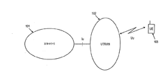
汎用移動体通信システム(UMTS)の上位レベルのR99/4/5構成を図1に示す(非特許文献1参照:http://www.3gpp.orgから入手可能)。この図において、ネットワーク要素は、機能的に、コアネットワーク(CN)101、UMTS地上無線アクセスネットワーク(UTRAN)102、およびユーザ装置(UE)103に分類される。UTRAN102は、全ての無線関連機能の処理を行い、一方、CN101は、呼およびデータ接続を外部ネットワークへルーティングする処理を行う。これらのネットワーク要素の相互接続は、オープンインタフェース(Iu、Uu)により定義される。UMTSシステムは、モジュール式であり、従って複数の同一タイプのネットワーク要素を持つことができることに留意されたい。
UMTS Configuration A high-level R99 / 4/5 configuration of a universal mobile communication system (UMTS) is shown in FIG. 1 (see Non-Patent Document 1: available from http://www.3gpp.org). In this figure, the network elements are functionally classified into a core network (CN) 101, a UMTS terrestrial radio access network (UTRAN) 102, and a user equipment (UE) 103. UTRAN 102 handles all radio related functions, while CN 101 routes calls and data connections to external networks. The interconnection of these network elements is defined by open interfaces (Iu, Uu). Note that the UMTS system is modular and thus can have multiple network elements of the same type.
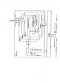
図2に現行のUTRANの構成を示す。複数の無線ネットワーク制御装置(RNC)201、202がCN101へ接続される。各RNC201、202は、一つまたは複数の基地局(ノードB)203、204、205、206の制御を行い、これらの基地局はUEと通信を行う。複数の基地局を制御するRNCは、これらの基地局の制御RNC(C−RNC)と呼ばれる。C−RNCを伴う、制御された基地局の一セットは、無線ネットワークサブシステム(RNS)207、208と呼ばれる。ユーザ装置およびUTRAN間の各接続に対して、一つのRNSがサービングRNS(S−RNS)となり、コアネットワーク(CN)101とのIu接続を維持する。必要に応じて、ドリフトRNS(D−RNS)302は、図3に示すように、無線リソースを提供することによってサービングRNS(S−RNS)301をサポートする。それぞれのRNCは、サービングRNC(S−RNC)およびドリフトRNC(D−RNC)と呼ばれる。C−RNCおよびD−RNCは同一であり、従ってS−RNCまたはRNCの略記も頻繁に用いられる。
FIG. 2 shows the current UTRAN configuration. A plurality of radio network controllers (RNCs) 201 and 202 are connected to the
進化型(Evolved)UTRAN構成
現在、現行のR99/4/5 UMTS構成からのUTRAN構成の進化に対する実現性の研究が進行中である(非特許文献2参照、http://www.3gpp.orgで入手可能)。上記進化型構成のための2つの概略提案が現れた(非特許文献3および非特許文献4参照、http://www.3gpp.orgで入手可能)。"Further Clarifications on the Presented Evolved Architecture"の表題でなされた提案につき、図4を参照して以下に議論する。
Evolved UTRAN Configuration Currently, research into the feasibility of UTRAN configuration evolution from the current R99 / 4/5 UMTS configuration is ongoing (see Non-Patent
RNG(無線ネットワークゲートウェイ)401は、従来のRANとの網間接続に使用され、モビリティアンカーポイントとして機能する。モビリティアンカーポイントは、一旦RNG401が接続のために選択されるとそれが呼の間維持されることを意味する。これは制御プレーンおよびユーザプレーンの両方の機能を含む。
An RNG (radio network gateway) 401 is used for inter-network connection with a conventional RAN and functions as a mobility anchor point. A mobility anchor point means that once
制御プレーンにおいて、RNG401は、進化型RANとCNとの間、および進化型RANとR99/4/5 UTRANとの間のシグナリングゲートウエイとしての役割を果たし、以下の主要な機能を有する。
In the control plane, the
●Iuシグナリングゲートウエイ、すなわちRANAP(無線アクセスネットワークアプリケーション部)接続用アンカーポイント
●RANAP接続の終端、以下を含む。
●シグナリング接続の設定および解除
●コネクションレスメッセージの識別
●RANAPコネクションレスメッセージの処理
●該当ノードB+へのアイドルおよび接続モードページングメッセージの中継
RNGは、以下を行う。
●ノードB+間再配置におけるCNの役割
●ユーザプレーン制御および
●ノードB+402〜405とR99/4/5 RNCとの間のIurシグナリングゲートウエイ
● Iu signaling gateway, that is, an anchor point for RANAP (Radio Access Network Application) connection ● Termination of RANAP connection, including:
● Signaling connection setup and release ● Connectionless message identification ● RANAP connectionless message processing ● Relay of idle and connection mode paging messages to the relevant Node B + The RNG:
● Role of CN in relocation between Node B + ● User plane control and ● Iur signaling gateway between Node B + 402-405 and R99 / 4/5 RNC
さらに、RNGは、CNまたは従来のRANから、進化型RANまでのユーザプレーンアクセスポイントであり、以下のユーザプレーン機能を有する。
●再配置中におけるユーザプレーントラフィック切り替え;
●ノードB+およびSGSN(サービングGPRSサポートノード、CNの要素)間におけるGTP(Iuインタフェースに関するGPRSトンネリングプロトコル)パケットの中継および
●ユーザプレーンに対するIur網間接続
Furthermore, RNG is a user plane access point from CN or conventional RAN to evolved RAN, and has the following user plane functions.
● User plane traffic switching during relocation;
Relay of GTP (GPRS tunneling protocol for Iu interface) packets between Node B + and SGSN (Serving GPRS support node, CN element) and Iur network connection to user plane
ノードB+402〜405要素は、RAN無線プロトコル(レイヤ1−物理レイヤ、レイヤ2−媒体アクセス制御および無線リンク制御サブレイヤ、レイヤ3−無線リソース制御)の全てを終端する。ノードB+402〜405の制御プレーン機能は、進化型RAN内の接続モード端末の制御に関する機能を全て含む。主要な機能には、以下を含む。
●UEの制御
●RANAP接続の終端
●RANAP接続指向プロトコルメッセージの処理
●RRC(無線リソース制御)接続の制御/終端および
●該当ユーザプレーン接続の初期化の制御
Node B + 402-405 elements terminate all of the RAN radio protocols (layer 1-physical layer, layer 2-medium access control and radio link control sublayer, layer 3-radio resource control). The control plane functions of the Node B + 402 to 405 include all functions related to connection mode terminal control in the evolved RAN. Key features include:
● Control of UE ● Termination of RANAP connection ● Processing of RANAP connection-oriented protocol messages ● Control / termination of RRC (Radio Resource Control) connection ● Control of initialization of corresponding user plane connection
RRC接続が終端されると、またはその機能が別のノードB+に再配置されると(サービングノードB+の移動)、UEのコンテキストは(サービング)ノードB+から除去される。制御プレーン機能は、ノードB+402〜405のセルのリソースの制御および設定のための全ての機能、ならびにサービングノードB+の制御プレーン部からの要求に応じた個別リソースの割当てを含む。「ノードB+」における「+」は、R99/4/5仕様書と比較して、基地局の機能が拡張されていることを表す。 When the RRC connection is terminated or its function is relocated to another Node B + (moving serving Node B +), the UE context is removed from the (Serving) Node B +. The control plane function includes all functions for control and setting of the resources of the cells of the Node B + 402 to 405, and allocation of individual resources in response to a request from the control plane unit of the serving Node B +. “+” In “Node B +” indicates that the function of the base station is expanded as compared with the R99 / 4/5 specification.
ノードB+402〜405のユーザプレーン機能は、PDCP(パケットデータ輻輳プロトコル)、RLC(無線リンク制御)およびMAC(媒体アクセス制御)のプロトコル機能、ならびにマクロダイバーシチ合成を含む。 User plane functions of Node B + 402-405 include PDCP (Packet Data Congestion Protocol), RLC (Radio Link Control) and MAC (Medium Access Control) protocol functions, and macro diversity combining.
拡張アップリンク個別チャネル
個別トランスポートチャネル(DTCH)用のアップリンクエンハンスメント(E−DCH)は、現在3GPP技術仕様書グループRANにより研究されている(非特許文献5参照、http://www.3gpp.orgで入手可能)。IPベースのサービスの利用はさらに重要になるので、アップリンク個別トランスポートチャネルの遅延を低減させるとともに、RANのカバー範囲およびスループットを改善する要求が増加している。ストリーミング、インタラクティブおよびバックグラウンドサービスはこの拡張アップリンクから恩恵を受けることができる。
Enhanced uplink dedicated channel Uplink enhancement (E-DCH) for dedicated transport channel (DTCH) is currently being studied by 3GPP technical specification group RAN (see Non-Patent Document 5, http: //www.3gpp). available at .org). As the use of IP-based services becomes more important, there is an increasing demand to reduce uplink dedicated transport channel delays and improve RAN coverage and throughput. Streaming, interactive and background services can benefit from this enhanced uplink.
エンハンスメントの一例は、ノードB制御スケジューリング(Node B controlled scheduling)に関連する適応変調符号化方式(AMC)の使用であり、すなわちUuインタフェースのエンハンスメントである。既存のR99/R4/R5のシステムでは、アップリンクの最大データレート制御はRNC内で行われる。ノードBのスケジューラを再配置することにより、RNCとノードBとの間のインタフェースのシグナリングより生じる待ち時間を低減させることができ、スケジューラはアップリンク負荷の時間的変化により速く対応することができる。これにより、UEとRANとの通信における全体的な待ち時間が低減される。従って、ノードB制御スケジューリングは、アップリンク負荷が低減する場合には、より高いデータレートを速やかに割り当てることにより、または、アップリンク負荷が増加する場合には、アップリンクデータレートを制限することにより、それぞれアップリンク干渉をより確かに制御するとともに雑音上昇の変動を平滑化することができる。セルのカバー範囲およびスループットは、アップリンク干渉をより確かに制御することで改善可能である。 An example of enhancement is the use of an adaptive modulation and coding scheme (AMC) associated with Node B controlled scheduling, ie, enhancement of the Uu interface. In existing R99 / R4 / R5 systems, uplink maximum data rate control is performed within the RNC. By relocating the Node B scheduler, the latency resulting from the signaling of the interface between the RNC and Node B can be reduced, and the scheduler can respond more quickly to changes in uplink load over time. This reduces the overall waiting time in communication between the UE and the RAN. Therefore, Node B control scheduling can be done by quickly allocating a higher data rate when the uplink load is reduced, or by limiting the uplink data rate when the uplink load is increased. In each case, it is possible to more reliably control uplink interference and smooth out fluctuations in noise rise. Cell coverage and throughput can be improved by more reliably controlling uplink interference.
アップリンク上の遅延を低減させると考えられる別の技術は、他のトランスポートチャネルと比較して短いTTI(送信時間間隔)長をE−DCHに対して導入する技術である。通常10msのTTIが他のチャネル上で使用されているが、2msのTTI長が現在、E−DCH上の利用に向けて研究されている。HSDPAの重要な技術の一つであるハイブリッドARQも、拡張アップリンク個別チャネル用に検討されている。ノードBおよびUE間のハイブリッドARQプロトコルは、誤って受信されたデータユニットの迅速な再送を可能とし、従ってRLC(無線リンク制御)再送の回数およびこれに係る遅延を低減させる。これにより、エンドユーザの経験するサービス品質を改善することができる。 Another technique that is believed to reduce the delay on the uplink is a technique that introduces a shorter TTI (Transmission Time Interval) length for E-DCH compared to other transport channels. A 10 ms TTI is typically used on other channels, but a 2 ms TTI length is currently being investigated for use on E-DCH. Hybrid ARQ, which is one of the important technologies of HSDPA, is also being studied for an enhanced uplink dedicated channel. The hybrid ARQ protocol between the Node B and the UE allows for rapid retransmission of erroneously received data units, thus reducing the number of RLC (Radio Link Control) retransmissions and the associated delay. Thereby, the service quality experienced by the end user can be improved.
上述のエンハンスメントをサポートするため、以下MAC−euと呼ぶ新MACサブレイヤを導入する(非特許文献6参照)。以下の章でさらに詳細に説明する、この新サブレイヤのエンティティは、UEとノードBに設置することができる。UE側では、MAC−euは、上位レイヤデータ(例えばMAC−d)を新しい拡張トランスポートチャネルに多重化するとともにHARQプロトコル送信エンティティを動作させる新しいタスクを実行する。 In order to support the above-described enhancement, a new MAC sublayer called MAC-eu will be introduced (see Non-Patent Document 6). This new sub-layer entity, described in more detail in the following sections, can be installed in the UE and Node B. On the UE side, the MAC-eu performs a new task to multiplex higher layer data (eg, MAC-d) into a new enhanced transport channel and operate the HARQ protocol transmitting entity.
UEにおけるE−DCH MAC構成
図5は、UE側のE−DCH MAC構成の全体を示す。新MAC機能エンティティであるMAC−eu503が、Rel/99/4/5のMAC構成に加えられる。MAC−eu503エンティティを図6に詳細に示す。
E-DCH MAC configuration in UE FIG. 5 shows the entire E-DCH MAC configuration on the UE side. A new MAC functional entity, MAC-
UEからノードBに送信されるデータパケットを搬送するM個の異なるデータフロー(MAC−d)が存在する。これらのデータフローは、種々のQoS(サービス品質)、例えば遅延および誤りの要件を有することができ、設定の異なるHARQインスタンスを用いてよい。従って、データパケットは、異なる優先度キューに格納することができる。UEおよびノードBにそれぞれ設置された、HARQ送受信エンティティのセットは、HARQ処理と呼ばれる。スケジューラは、HARQ処理を異なる優先度キューに割り当てる際、QoSパラメータを考慮する。MAC−euエンティティは、レイヤ1のシグナリングを介しノードB(ネットワーク側)からスケジューリング情報を受信する。
There are M different data flows (MAC-d) that carry data packets transmitted from the UE to the Node B. These data flows may have different QoS (Quality of Service), eg delay and error requirements, and may use differently configured HARQ instances. Thus, data packets can be stored in different priority queues. The set of HARQ transmission / reception entities installed in the UE and Node B, respectively, is called HARQ processing. The scheduler considers QoS parameters when assigning HARQ processes to different priority queues. The MAC-eu entity receives scheduling information from Node B (network side) via
UTRANにおけるE−DCH MAC構成
ソフトハンドオーバー動作では、UTRAN側のE−DCH MAC構成におけるMAC−euエンティティは、ノードB(MAC−eub)およびS−RNC(MAC−eur)間で分散することができる。ノードBのスケジューラは、アクティブユーザを選択し、指示されたレート、提示されたレート、または送信が許可されたTCFS(トランスポートフォーマットコンビネーションセット)のサブセットにアクティブユーザ(UE)を制限するTFC(トランスポートフォーマットコンビネーション)閾値を決定するとともにシグナリングすることにより、レート制御を行なう。
E-DCH MAC configuration in UTRAN In soft handover operation, MAC-eu entities in E-DCH MAC configuration on the UTRAN side may be distributed between Node B (MAC-eub) and S-RNC (MAC-eur). it can. The Node B scheduler selects the active user and limits the active user (UE) to the indicated rate, the presented rate, or a subset of the TCFS (Transport Format Combination Set) that is allowed to transmit. Port format combination) Rate control is performed by determining and signaling a threshold.
各MAC−euエンティティは一ユーザ(UE)に対応している。図7に、ノードBのMAC−eu構成をさらに詳細に示す。各HARQ受信機エンティティは、未解決の再送からのパケットのビットを合成するために一定量または一定領域のソフトバッファメモリを割り当てられることに留意されたい。一旦パケットが正常に受信されると、パケットは、順序通りの送出(in-sequence delivery)を上位レイヤに提供する並べ替えバッファ(reordering buffer)へ転送される。上述の実施形態によれば、並べ替えバッファは、ソフトハンドオーバー中、S−RNC内に存在する(非特許文献7参照、http://www.3gpp.orgから入手可能)。図8に、対応するユーザ(UE)の並べ替えバッファを含むS−RNC MAC−eu構成を示す。並べ替えバッファの数は、UE側での対応するMAC−euエンティティにおけるデータフローの数と等しい。データおよび制御情報は、ソフトハンドオーバー中に、アクティブセット内の全てのノードBからS−RNCへ送信される。 Each MAC-eu entity corresponds to one user (UE). FIG. 7 shows the MAC-eu configuration of Node B in more detail. Note that each HARQ receiver entity is allocated a certain amount or region of soft buffer memory to synthesize the bits of the packet from the outstanding retransmissions. Once a packet is successfully received, the packet is forwarded to a reordering buffer that provides in-sequence delivery to higher layers. According to the above-described embodiment, the reordering buffer exists in the S-RNC during soft handover (see Non-Patent Document 7, available from http://www.3gpp.org). FIG. 8 shows an S-RNC MAC-eu configuration including a corresponding user (UE) reordering buffer. The number of reordering buffers is equal to the number of data flows in the corresponding MAC-eu entity on the UE side. Data and control information is transmitted from all Node Bs in the active set to the S-RNC during soft handover.
必要とされるソフトバッファの大きさは、使用されるHARQ方式に依存することに留意されたい。例えば、増加的冗長性(IR)を利用するHARQ方式においては、チェイス合成(CC)を備える場合よりも多くのソフトバッファが必要になる。 Note that the required soft buffer size depends on the HARQ scheme used. For example, in the HARQ scheme that uses incremental redundancy (IR), more soft buffers are required than with chase combining (CC).
E−DCHシグナリング
特定の方式の動作に必要なE−DCH関連の制御シグナリングは、アップリンクおよびダウンリンクのシグナリングより成る。シグナリングは、考慮されるアップリンクエンハンスメントに依存する。
E-DCH signaling The E-DCH related control signaling required for the operation of a particular scheme consists of uplink and downlink signaling. Signaling depends on the uplink enhancement being considered.
ノードB制御スケジューリング(例えば、ノードB制御の時間レートスケジューリング(time and rate scheduling))を可能にするには、UEは、データをノードBへ送信するために要求メッセージをアップリンク上において送信する必要がある。上記要求メッセージは、UEのステータス情報(例えば、バッファステータス、電力ステータス、チャネル品質推定)を含むことができる。この情報に基づき、ノードBは、雑音上昇を推定し、UEのスケジューリングを行うことができる。ダウンリンクにおいてノードBからUEへ送信される許可メッセージにより、ノードBは、UEが送信を許可される最大データレートおよび時間間隔を有するTFCSをUEに割り当てる。 To enable Node B control scheduling (eg, Node B controlled time and rate scheduling), the UE needs to send a request message on the uplink to send data to Node B. There is. The request message may include UE status information (eg, buffer status, power status, channel quality estimation). Based on this information, Node B can estimate the noise rise and schedule the UE. With a grant message sent from the Node B to the UE in the downlink, the Node B assigns the UE a TFCS with the maximum data rate and time interval that the UE is allowed to send.
アップリンクにおいて、UEは、送信されたパケットを正しく復号するために必要なレート指標メッセージ情報(例えば、トランスポートブロックサイズ(TBS)、変調符号化方式(MCS)レベル等)を、ノードBへシグナリングする必要がある。さらに、HARQを用いる場合、UEは、HARQ関連の制御情報(例えば、ハイブリッドARQ処理番号、UMTSリリース5の新規データ表示(NDI)と呼ばれるHARQシーケンス番号、冗長性バージョン(RV)、レートマッチングパラメータ等)をシグナリングする必要がある。 In the uplink, the UE signals rate indicator message information (eg, transport block size (TBS), modulation and coding scheme (MCS) level, etc.) necessary to correctly decode the transmitted packet to the Node B. There is a need to. Furthermore, when using HARQ, the UE may control information related to HARQ (eg, hybrid ARQ process number, HARQ sequence number called new data display (NDI) of UMTS release 5), redundancy version (RV), rate matching parameter, etc. ) Must be signaled.
拡張アップリンク個別チャネル(E−DCH)上で送信されたパケットを受信し、復号化した後、ノードBは、ダウンリンクにおいてACK/NAKを送信することで、送信が成功したか否かをUEに通知する必要がある。 After receiving and decoding the packet sent on the enhanced uplink dedicated channel (E-DCH), the Node B sends an ACK / NAK on the downlink to determine whether the transmission was successful. Need to be notified.
R99/4/5のUTRAN内のモビリティ管理
この章では、頻繁に使用される用語を簡潔に定義し、モビリティ管理の手順を概説する(非特許文献8参照、http://www.3gpp.orgで入手可能)。
Mobility Management in R99 / 4/5 UTRAN This chapter briefly defines frequently used terms and outlines mobility management procedures (see Non-Patent Document 8, http://www.3gpp.org). Available at:
無線リンクは、単一のUEと単一のUTRANアクセスポイントとの間の論理結合である。その物理的具現例は、無線ベアラー送信を含む。 A radio link is a logical connection between a single UE and a single UTRAN access point. Its physical implementation includes radio bearer transmission.
ハンドオーバーは、一つの無線ベアラーから別のベアラーへのユーザ接続の移動として定義できる。「ハードハンドオーバー」では、新しい無線リンクが確立される。一方、「ソフトハンドオーバー」(SHO)においては、UEがUTRANに対し常に少なくとも一つの無線リンクを維持するよう、無線リンクが確立、放棄される。ソフトハンドオーバーは、符号分割多重アクセス(CDMA)技術を用いるネットワークに特有のものである。通常、ハンドオーバーの実行は、移動体無線ネットワークのS−RNCにより制御される。 Handover can be defined as the movement of a user connection from one radio bearer to another. In “hard handover”, a new radio link is established. On the other hand, in “soft handover” (SHO), a radio link is established and abandoned so that the UE always maintains at least one radio link to UTRAN. Soft handover is unique to networks that use code division multiple access (CDMA) technology. Usually, the execution of the handover is controlled by the S-RNC of the mobile radio network.
「アクティブセット」は、UEと無線ネットワークとの間の特定の通信サービスに同時に関与する一セットの無線リンクを含む。例えば、ソフトハンドオーバー中、UEのアクティブセットは、UEに対してサービングするRANのノードBへの無線リンク全てを含む。 An “active set” includes a set of radio links that are simultaneously involved in a particular communication service between a UE and a radio network. For example, during soft handover, the UE's active set includes all radio links to the Node Bs of the RAN serving the UE.
UEとUTRANとの間の通信のアクティブセットを変更するために、アクティブセット更新手順を用いてよい。その手順は3つの機能、すなわち無線リンクの追加、無線リンクの除去、ならびに無線リンクの追加および除去の組み合わせを含む。通常、同時無線リンクの最大数は4に設定される。一旦、各基地局のパイロット信号強度がアクティブセットの中で最も強度の高いメンバーのパイロット信号に対する特定の閾値を越えると、新しい無線リンクをアクティブセットへ加えることができる。一旦、各基地局のパイロット信号強度がアクティブセットの中で最も強度の高いメンバーのパイロット信号に対する特定の閾値を越えると、無線リンクをアクティブセットから除去することができる。 An active set update procedure may be used to change the active set of communications between the UE and the UTRAN. The procedure includes a combination of three functions: radio link addition, radio link removal, and radio link addition and removal. Usually, the maximum number of simultaneous radio links is set to four. Once the pilot signal strength of each base station exceeds a certain threshold for the strongest member pilot signal in the active set, a new radio link can be added to the active set. Once the pilot signal strength of each base station exceeds a certain threshold for the strongest member pilot signal in the active set, the radio link can be removed from the active set.
無線リンクの追加に対する閾値は通常、無線リンクの除去の場合よりも高くなるよう選択される。従って、上記追加と除去の事象はパイロット信号強度に対しヒステリシスを形成する。 The threshold for addition of a radio link is usually selected to be higher than in the case of radio link removal. Thus, the addition and removal events form a hysteresis with respect to the pilot signal strength.
パイロット信号の測定は、RRCシグナリングにより、UEからネットワーク(S−RNC)へ報告される。測定結果を送信する前に、高速フェージングを平均化するために、通常何らかのフィルタリングが行なわれる。標準的なフィルタリングの継続時間は約200msであり、これはハンドオーバー遅延の一要因となる(非特許文献9参照、http://www.3gpp.orgで入手可能)。測定結果に基づき、S−RNCは、アクティブセット更新手順の機能(現在のアクティブセットに対するノードBの追加/除去)の一つの実行開始を決定する。 The measurement of the pilot signal is reported from the UE to the network (S-RNC) by RRC signaling. Before sending the measurement results, some filtering is usually performed to average the fast fading. The standard filtering duration is about 200 ms, which contributes to handover delay (see Non-Patent Document 9, available at http://www.3gpp.org). Based on the measurement results, the S-RNC decides to start one of the functions of the active set update procedure (add / remove Node B to / from the current active set).
ソフトハンドオーバー中のE−DCH動作
マクロダイバーシチ利得を得るには、ソフトハンドオーバーをサポートすることが望ましい。HSDPAでは、例えば、ソフトハンドオーバーは、HS−DSCH(高速ダウンリンク共有チャネル)トランスポートチャネルに対してサポートされていない。ソフトハンドオーバーを適用した場合、アクティブセットの全ノードBに対するスケジューリング負担の分散の問題が生じる。そして、スケジューリング機能の分散が解決されたとしても、アクティブセットの全てのメンバーへスケジューリングの決定を供給するためには、非常に厳しいタイミングが求められる。一つのノードBのみがHS−DSCH上でUEへ送信を行うため、マクロダイバーシチ利得は得られない。UEが個別チャネルのソフトハンドオーバー領域に入ったとき、HS−DSCH上での送信が許可されたノードBを決定する必要がある。サービングノードBの選択は、UE側または(RNCにより)ネットワーク側のいずれで行ってもよい。
E-DCH operation during soft handover To obtain macro diversity gain, it is desirable to support soft handover. In HSDPA, for example, soft handover is not supported for HS-DSCH (High Speed Downlink Shared Channel) transport channels. When soft handover is applied, there arises a problem of distribution of scheduling burden for all Node Bs in the active set. And even if the distribution of scheduling functions is resolved, very strict timing is required to supply scheduling decisions to all members of the active set. Since only one Node B transmits to the UE on the HS-DSCH, no macro diversity gain is obtained. When the UE enters the soft handover area of the dedicated channel, it is necessary to determine the Node B that is allowed to transmit on the HS-DSCH. The selection of the serving Node B may be performed either on the UE side or on the network side (by RNC).
HS−DSCH用の高速セル選択(FCS)法では、UEは、データ送信に最も好適なセルを選択する。UEは、周期的にアクティブセット内のセルのチャネル状態を監視し、現在のサービングセルよりさらに良好なチャネル状態のセルがあるか否か判定する。 In the fast cell selection (FCS) method for HS-DSCH, the UE selects the most suitable cell for data transmission. The UE periodically monitors the channel conditions of the cells in the active set to determine if there are cells with better channel conditions than the current serving cell.
ソフトハンドオーバーがアップリンク用にサポートされていない場合は、サービングノードBを選択する必要がある。起こり得る一つの問題は、サービングノードBの誤選択である。従って、選択されたアップリンクサービングノードBよりもアップリンク送信に好適な、アクティブセット内のセルがある。このため、現在のサービングノードBにより制御されるセルへのデータ送信が失敗し得る一方、他のノードBにより制御されたセルへの送信は成功していたかもしれない。この選択の精度は、シグナリング遅延、測定結果のフィルタリング等、複数の要因に依存する。 If soft handover is not supported for the uplink, the serving Node B needs to be selected. One problem that can occur is the misselection of the serving Node B. Thus, there are cells in the active set that are more suitable for uplink transmission than the selected uplink serving Node B. Thus, while data transmission to a cell controlled by the current serving Node B may fail, transmissions to cells controlled by other Node Bs may have been successful. The accuracy of this selection depends on a number of factors, such as signaling delay and measurement result filtering.
結論として、E−DCHに対するSHO動作をサポートすることは、マクロダイバーシチ利得を得ることができ、さらに最良のアップリンクサービングノードBの誤選択より発生し得る送信失敗を排除できる点において有用である。 In conclusion, supporting SHO operation for E-DCH is useful in that it can achieve macro diversity gain and further eliminate transmission failures that can occur due to the wrong selection of the best uplink serving Node B.
ソフトハンドオーバーにおけるHARQ動作
ソフトハンドオーバー中にHARQを用いる場合、UEはアップリンクにおいて複数のノードBへ送信を行う。ソフトハンドオーバー中のHARQ動作に関する主な問題の一つは、複数ノードB間におけるHARQソフトバッファの同期である。アクティブセットの全てのノードBが、受信パケットの正確な処理に必要な制御シグナリングを、UEから受信できるわけではない。対応するノードB(「最良アップリンクノードB」と呼ぶ)はパケットを正しく受信、復号できるのに対し、アクティブセット内の他のノードBは、一部のパケットを正常に受信できない可能性が高い。
HARQ operation in soft handover When using HARQ during soft handover, the UE transmits to multiple Node Bs in the uplink. One of the main problems with HARQ operation during soft handover is the synchronization of HARQ soft buffers between multiple Node Bs. Not all Node Bs in the active set can receive control signaling from the UE that is necessary for the correct processing of received packets. The corresponding Node B (referred to as “Best Uplink Node B”) can receive and decode packets correctly, while other Node Bs in the active set are likely not to receive some packets successfully. .
アクティブセット内のノードBに対応するアップリンク無線チャネルは無相関であるので、ソフトハンドオーバーからのダイバーシチ利得が可能である。SHO中、アップリンク方向において、異なるノードBにより受信されたパケットは、合成のためにS−RNCへルーティングされる(非特許文献10参照)。これは通常、あるフレーム信頼性指標を用いてS−RNCにおける全ての候補から最良のフレームを選択して行われる。 Since the uplink radio channel corresponding to the Node B in the active set is uncorrelated, diversity gain from soft handover is possible. During SHO, packets received by different Node Bs in the uplink direction are routed to the S-RNC for synthesis (see Non-Patent Document 10). This is usually done by selecting the best frame from all candidates in the S-RNC using a certain frame reliability index.
IUB/IURインタフェースシグナリング
MAC−euプロトコルがS−RNCで終端される場合、S−RNCは、受信情報をフィルタリングして、これに従って並べ替えバッファの内容とインデックスを更新することができる。非同期シグナリングの場合は、フィルタリングはシーケンス番号に基づいてよい。次に、正しく受信されたパケットは、並べ替えバッファの適切な位置に配置されなければならない。
IUB / IUR interface signaling When the MAC-eu protocol is terminated at the S-RNC, the S-RNC can filter the received information and update the contents and index of the reordering buffer accordingly. In the case of asynchronous signaling, filtering may be based on sequence numbers. The correctly received packet must then be placed in the appropriate position in the reordering buffer.
ソフトハンドオーバー中の拡張個別アップリンクチャネル動作のサポートには、過去の3GPPリリースにおけるシグナリング量と比較して付加的なIub/Iurシグナリングトラフィックを必要とする場合があることに留意されたい。上述したように、アクティブセット内の全てのノードBは、Iub/Iurインタフェースを通してS−RNCに制御情報とデータパケットをシグナリングする必要がある。例えば、シグナリングは、以前の3GPPリリース(Rel99/4/5)では、アップリンク個別チャネルのアウターループ電力制御とソフトハンドオーバー動作において必要であった。 Note that support of enhanced dedicated uplink channel operation during soft handover may require additional Iub / Iur signaling traffic compared to the amount of signaling in past 3GPP releases. As described above, all Node Bs in the active set need to signal control information and data packets to the S-RNC through the Iub / Iur interface. For example, signaling was required in the outer loop power control and soft handover operation of the uplink dedicated channel in previous 3GPP releases (Rel99 / 4/5).
アウターループ電力制御は、個別チャネルとダウンリンク共有チャネル(DSCH)によりサポートできる。その動機は、送信される電力を制御することにより、接続の存続期間を通じて様々なサービス(例えば音声、ストリーミング)に対する一定のQoS(サービス品質)の維持である。 Outer loop power control can be supported by dedicated channels and downlink shared channels (DSCH). The motivation is to maintain a constant quality of service (QoS) for various services (eg voice, streaming) over the lifetime of the connection by controlling the power transmitted.
アップリンクの閉ループ電源制御において、ノードBは、頻繁に受信信号対干渉比(SIR)の推定を行ない、この推定と、S−RNCにより設定された対応の目標SIRとを比較することができる。S−RNCはノードBへ目標SIRを送信することができる。DCHのFP(フレームプロトコル)は、S−RNCとノードBとの間のアウターループ電力制御情報の伝送を実現する(非特許文献11参照、http://www.3gpp.orgで入手可能)。 In uplink closed loop power control, the Node B can frequently estimate the received signal-to-interference ratio (SIR) and compare this estimate with the corresponding target SIR set by the S-RNC. The S-RNC can send the target SIR to the Node B. The DCH FP (Frame Protocol) implements transmission of outer loop power control information between the S-RNC and the Node B (see Non-Patent Document 11, available at http://www.3gpp.org).
アウターループ電力制御の頻度は10〜100Hzである。さらなるIub/Iurシグナリングが、アップリンクでのソフトハンドオーバー動作中に必要になることがあり、アクティブセット内のノードBは、受信パケットをS−RNCに送信する。これらパケットのヘッダーは、受信パケットの品質についての情報(品質指標(Quality Indicator))を含む。S−RNCは、最良の品質指標を有するパケットを選択することができ、これは一般的に選択合成(selection combining)と呼ばれる(非特許文献10の3.6章参照)。UMTS R99/4/5において必要なIub/Iurインタフェースを通じ、かなり大量のシグナリングが既に存在することに留意されたい。 The frequency of outer loop power control is 10 to 100 Hz. Further Iub / Iur signaling may be required during soft handover operations on the uplink, and the Node B in the active set sends the received packet to the S-RNC. These packet headers contain information about the quality of the received packet (Quality Indicator). The S-RNC can select a packet having the best quality index, which is generally called selection combining (see Chapter 3.6 of Non-Patent Document 10). Note that there is already a significant amount of signaling through the Iub / Iur interface required in UMTS R99 / 4/5.
さらに、インフラストラクチャーを展開する上での高価な部分は、ノードBがネットワークに接続される、いわゆる「ラストマイル」である。ネットワーク内の他の有線リンクと比べると、このリンクは比較的小さな帯域幅のものでよい。通常、他のトラフィックとの多重化があり得るトラフィックはなく、必要な帯域幅は、ノードBとRNCとの間で送信されるトラフィックによってのみ定義される。 Furthermore, an expensive part of deploying the infrastructure is the so-called “last mile” where Node B is connected to the network. Compared to other wired links in the network, this link may have a relatively small bandwidth. Usually there is no traffic that can be multiplexed with other traffic, and the required bandwidth is defined only by the traffic transmitted between the Node B and the RNC.
HSDPAによる改善されたダウンリンク送信、または将来の拡張アップリンク送信等の新機能が、ノードBに頻繁に追加される。これらのエンハンスメントにより、無線でのシステムスループットが増大し、従ってIub/Iurインタフェースのトラフィックが増加する。
本発明の目的は、基地局と制御ユニットとの間の有線インタフェースのシグナリング負荷を低減させることである。UTRANを例にとると、上記目的は、ノードBへの「ラストマイル」上(すなわちノードBをRNCまたは次のホップへ接続するリンク)のIub/Iurユーザトラフィックを低減させることである。この目的の達成により、オペレータのインフラストラクチャー投資を低減させることができる。 The object of the present invention is to reduce the signaling load of the wired interface between the base station and the control unit. Taking UTRAN as an example, the objective is to reduce Iub / Iur user traffic on the “last mile” to Node B (ie the link connecting Node B to the RNC or next hop). By achieving this objective, the operator's infrastructure investment can be reduced.
本目的は、独立請求項で定義される発明により達成される。本発明の別の実施の形態は従属請求項で定義される。 This object is achieved by the invention as defined in the independent claims. Further embodiments of the invention are defined in the dependent claims.
本発明によれば、各基地局と制御ユニット等の次のホップとの間の有線インタフェースでの通信のためのサービング基地局を選択して、「ラストマイル」上のトラフィックを最小化することができる。別の実施の形態によれば、RNC等の制御ユニットは、以下に概説するように、特定の選択基準に基づいて最適のサービングノードBを選択することができる。移動体通信ネットワーク用のUMTS構成を例にとると、ソフトハンドオーバー中のIub/Iurシグナリング量を最小化するために、最初に、アクティブセットの一つのノードB(いわゆるサービングノードB)のみが、データパケットおよび/または制御パケットをRNCへ送信することができる。サービングノードBは、アクティブセット内の全てのノードBの中で、UEから正確にデータパケットを受信する最も高い確率を持つ基地局に相当する。従って、その選択はアップリンクチャネル品質測定に基づく。サービング基地局がパケットを正しく受信できなかった場合、他のノードBに依頼しパケットを制御ユニットへ送信する。 According to the present invention, the serving base station for communication on the wired interface between each base station and the next hop such as the control unit can be selected to minimize traffic on the “last mile”. it can. According to another embodiment, a control unit such as an RNC may select the optimal serving Node B based on specific selection criteria, as outlined below. Taking the UMTS configuration for a mobile communication network as an example, in order to minimize the amount of Iub / Iur signaling during soft handover, only one Node B in the active set (so-called serving Node B) is initially Data packets and / or control packets can be sent to the RNC. Serving Node B corresponds to the base station with the highest probability of correctly receiving data packets from the UE among all Node Bs in the active set. The selection is therefore based on uplink channel quality measurements. If the serving base station cannot correctly receive the packet, it requests another Node B to transmit the packet to the control unit.
一実施の形態によれば、本発明は、通信端末、複数の基地局および複数の基地局へ接続された制御ユニットを含む移動体通信システムにおいて複数の基地局を制御する方法を提供する。本方法によれば、通信端末は、ソフトハンドオーバー中に、複数の基地局と通信を行うことができる。上記複数の基地局は、移動体通信ネットワークの制御ユニットまたは複数の制御ユニットにより制御される全ての基地局を指すのではなく、ソフトハンドオーバー中に通信端末と通信を行う基地局を指すことに留意されたい。UMTSにおいては、この複数の基地局は通信端末のアクティブセットと呼ばれる。従って、上記複数の基地局は、移動体通信ネットワークでの通信に利用可能な基地局のサブセットであってよい。 According to one embodiment, the present invention provides a method for controlling a plurality of base stations in a mobile communication system including a communication terminal, a plurality of base stations, and a control unit connected to the plurality of base stations. According to this method, the communication terminal can communicate with a plurality of base stations during soft handover. The plurality of base stations indicate not all base stations controlled by a mobile communication network control unit or a plurality of control units, but a base station that communicates with a communication terminal during soft handover. Please keep in mind. In UMTS, this plurality of base stations is called an active set of communication terminals. Accordingly, the plurality of base stations may be a subset of base stations that can be used for communication in a mobile communication network.
複数の基地局の各基地局に関しては、通信端末と各基地局との間のアップリンクチャネル品質特性を評価することができ、最良のアップリンクチャネル品質特性を有する基地局を決定することができる。 For each base station of multiple base stations, the uplink channel quality characteristics between the communication terminal and each base station can be evaluated, and the base station with the best uplink channel quality characteristics can be determined .
さらに、ソフトハンドオーバー中に通信端末装置から受信したデータパケットを制御ユニットに転送する必要がないよう、サービング基地局として決定された基地局およびサービング基地局以外の複数または全ての基地局を、制御することができる。すなわち、サービング基地局またはサービングノードBを含む複数の基地局のサブセットのみが、正確に受信されたデータパケットまたは制御情報を、例えば通知形式で、制御ユニット(例えばRNC)へ転送することができる。 Furthermore, the base station determined as the serving base station and a plurality of base stations other than the serving base station or all the base stations other than the serving base station are controlled so that the data packet received from the communication terminal apparatus during the soft handover need not be transferred to the control unit. can do. That is, only a subset of a plurality of base stations including a serving base station or serving Node B can forward correctly received data packets or control information to a control unit (eg, RNC), eg, in a notification format.
別の実施の形態によれば、通信端末からのデータパケットは複数の基地局で受信することができ、受信されたデータパケットのデータの完全性を複数の基地局それぞれにおいて判定することができる。受信データパケットのデータの完全性が、受信データパケットを制御ユニットへ転送するよう制御された基地局により確認された場合、受信データパケットおよび/または制御パケットは、各基地局から制御ユニットへ送信される。上記制御パケットは、データパケットの正しい受信を肯定応答するものである。 According to another embodiment, data packets from a communication terminal can be received by a plurality of base stations, and data integrity of the received data packets can be determined at each of the plurality of base stations. If the data integrity of the received data packet is confirmed by the base station controlled to forward the received data packet to the control unit, the received data packet and / or control packet is transmitted from each base station to the control unit. The The control packet acknowledges the correct reception of the data packet.
さらに、本発明の別の実施の形態によれば、受信データパケットのデータの完全性が基地局により肯定応答されなかった場合、通知が、各基地局から制御ユニットへ送信される。この通知は、受信データパケットのデータの完全性が各基地局により肯定応答されなかったことを示すものである。 Furthermore, according to another embodiment of the invention, a notification is transmitted from each base station to the control unit if the data integrity of the received data packet has not been acknowledged by the base station. This notification indicates that the data integrity of the received data packet has not been acknowledged by each base station.
本発明のさらに別の実施の形態では、サービングノードBのみが制御ユニットと通信を行うことを許可される。すなわち、アクティブセットの他の全ての基地局または複数の基地局は、受信データパケットと関係するいかなるデータも制御ユニット(例えば、Iur/Iubインタフェース)への送信を許されない。受信データパケットのデータの完全性がサービング基地局により肯定応答されなかった場合、通知が、制御ユニットへ送信される。この通知は、受信データパケットのデータの完全性がサービング基地局により肯定応答されなかったことを示すものである。 In yet another embodiment of the invention, only the serving Node B is allowed to communicate with the control unit. That is, all other base stations or base stations in the active set are not allowed to transmit any data related to the received data packet to the control unit (eg, Iur / Iub interface). If the data integrity of the received data packet has not been acknowledged by the serving base station, a notification is sent to the control unit. This notification indicates that the data integrity of the received data packet has not been acknowledged by the serving base station.
サービング基地局からの通知の受信に応じ、制御ユニットは、選択された基地局以外の基地局からの受信データパケットに関するステータス要求を送信してもよく、従って、他の基地局からの受信データパケットに関するステータスレポートを受信してもよい。ステータスレポートは、データパケットのデータの完全性が各基地局で確認されたか否かを示すものであるか、または、受信データパケットを含むものである。 In response to receiving a notification from the serving base station, the control unit may send a status request for a received data packet from a base station other than the selected base station, and thus receive data packets from other base stations. A status report may be received. The status report indicates whether the data integrity of the data packet has been confirmed at each base station, or includes a received data packet.
別の実施の形態では、上記通知とステータスレポートは、少なくとも一つのフレームプロトコル(FP)制御フレーム中において、または有線インタフェースを通じた無線ネットワークシグナリングにより、制御ユニットへ送信される。UMTSでは、有線インタフェースを通じた無線ネットワークシグナリングは、RNSA(無線ネットワークサブシステムアプリケーション部)またはNBAP(ノードBアプリケーション部)のプロトコルメッセージと呼ばれる。 In another embodiment, the notification and status report are sent to the control unit in at least one Frame Protocol (FP) control frame or by wireless network signaling over a wired interface. In UMTS, wireless network signaling through a wired interface is called RNSA (Radio Network Subsystem Application Part) or NBAP (Node B Application Part) protocol message.
サービングノードBを選択する際に考慮されるほとんどのパラメータは、RNCで容易に入手できるので、サービング基地局の選択は制御ユニットにより実行できる。 Since most of the parameters considered in selecting the serving Node B are readily available at the RNC, the selection of the serving base station can be performed by the control unit.
サービング基地局の選択処理において考慮されるアップリンクチャネル品質特性は、通信端末と各基地局との間のアップリンクチャネルの経路損失、基地局により通信端末へ送信された閉ループ電源制御コマンド、およびアップリンク干渉のうちの少なくともいずれかに基づいて決定することができる。 Uplink channel quality characteristics considered in the serving base station selection process include the path loss of the uplink channel between the communication terminal and each base station, the closed loop power control command sent to the communication terminal by the base station, and the up It can be determined based on at least one of the link interference.
さらに、サービング基地局の選択は、設定可能なタイマーにより周期的に行われる。従って、サービング基地局の選択を周期的に再考することにより、必要に応じて新しいサービングノードBを選択して、変化するアップリンクチャネル条件に適応できる。 Furthermore, the selection of the serving base station is periodically performed by a configurable timer. Therefore, by periodically reviewing the selection of the serving base station, a new serving Node B can be selected as needed to adapt to changing uplink channel conditions.
タイマーの値は、無線リンクの追加機能、または無線リンクの追加および除去機能の組み合わせにより、上記サービング基地局へシグナリングすることができる。 The timer value can be signaled to the serving base station by a radio link addition function or a combination of radio link addition and removal functions.
さらに、タイマーの値は、NBAPまたはRNSAP無線リンク設定要求メッセージの情報要素の中で、上記サービング基地局へシグナリングすることができる。 Furthermore, the timer value can be signaled to the serving base station in the information element of the NBAP or RNSAP radio link setup request message.
アップリンクチャネル品質特性を評価する工程では、アップリンクチャネル品質を表すパラメータは、設定可能な時間間隔にわたって平均化することができる。上記時間間隔は、無線リソース管理(RRC)プロトコルの少なくとも一つのシグナリングメッセージ、または少なくとも一つのシステム専用制御プレーンプロトコルメッセージにより、設定することができる。上記時間間隔は、通信端末の移動速度、制御ユニットと基地局との間(例えば、ノードBおよびRNC間のUMTS Iubインタフェース)のシグナリング遅延、および移動体通信システム内の異なる制御ユニット間(例えば、RNC間のUMTS Iurインタフェース)のシグナリング遅延を考慮して選択される。 In the step of evaluating uplink channel quality characteristics, parameters representing uplink channel quality can be averaged over a configurable time interval. The time interval may be set by at least one signaling message of a radio resource management (RRC) protocol or at least one system-specific control plane protocol message. The time interval includes the moving speed of the communication terminal, the signaling delay between the control unit and the base station (eg, UMTS Iub interface between Node B and RNC), and between different control units in the mobile communication system (eg, It is selected taking into account the signaling delay of the UMTS Iur interface between RNCs.
制御ユニットが、サービング基地局として前記複数の基地局の中の新しい基地局を選択することを決定した場合、制御ユニットは、選択し次第、新しいサービング基地局に選択コマンドを送信することができる。さらに上記選択コマンドは以前のサービング基地局へも送信することができる。 If the control unit decides to select a new base station among the plurality of base stations as a serving base station, the control unit can send a selection command to the new serving base station upon selection. Furthermore, the selection command can be transmitted to the previous serving base station.
上記選択コマンドは、新しいサービング基地局が、正常に受信したデータパケット、制御パケット、または通知を制御ユニットへ転送することを開始し、かつ以前のサービング基地局が、正常に受信したデータパケット、制御パケット、または通知を制御ユニットへ転送することを停止する時間を、指示する。これは、サービングノードBの非同期変更によるソフトハンドオーバー中のパケット損失を防ぐために重要である。さらに、別の実施の形態では、以前の、すなわち「古い」サービング基地局と新しく選択されたサービング基地局との両者が、所定の時間、または以前のサービング基地局が制御ユニットから転送を停止するための別のコマンドを受信するまで、制御ユニットへデータパケット、制御パケット、および通知を転送することができる。 The selection command initiates that the new serving base station starts forwarding successfully received data packets, control packets, or notifications to the control unit, and the previous serving base station successfully received data packets, control Indicates the time to stop forwarding packets or notifications to the control unit. This is important to prevent packet loss during soft handover due to asynchronous changes in the serving Node B. Further, in another embodiment, both the previous or “old” serving base station and the newly selected serving base station stop transferring from the control unit for a predetermined time or the previous serving base station. Data packets, control packets, and notifications can be transferred to the control unit until another command is received.
さらに、別の実施の形態では、以前のサービング基地局と制御ユニットは制御メッセージを交換することにより起動時間をネゴシエーションすることができる。 Furthermore, in another embodiment, the previous serving base station and the control unit can negotiate activation times by exchanging control messages.
このような制御メッセージは、NBAPまたはRNSAPプロトコルの無線リンク再設定メッセージ、起動時間ネゴシエーション要求メッセージ、または起動時間確認メッセージのうちのいずれかでよい。 Such a control message may be one of an NBAP or RNSAP protocol radio link reconfiguration message, an activation time negotiation request message, or an activation time confirmation message.
別の実施の形態によれば、本発明は、進化型UTRAN構成に適用することができる。従って、本発明は、通信端末、複数の基地局、ならびに移動体通信ネットワークおよび固定通信ネットワークを相互接続するゲートウェイを含む移動体通信システムにおいて、複数の基地局を制御する方法を提供する。進化型UTRAN構成では、このゲートウェイはRNGである。通信端末は、ソフトハンドオーバー中、複数の基地局と通信を行うことができる。また、上記複数の基地局は、移動体通信ネットワークの制御ユニットまたは複数の制御ユニットにより制御される全ての基地局を指すのではなく、ソフトハンドオーバー中に通信端末と通信を行う基地局を指すことに留意されたい。UMTSでは、この複数の基地局を通信端末のアクティブセットと呼ぶ。従って、複数の基地局は、移動体通信ネットワークにおける通信に対して利用可能な基地局のサブセットであってよい。 According to another embodiment, the present invention can be applied to an evolved UTRAN configuration. Accordingly, the present invention provides a method for controlling a plurality of base stations in a mobile communication system including a communication terminal, a plurality of base stations, and a gateway interconnecting the mobile communication network and the fixed communication network. In the evolved UTRAN configuration, this gateway is RNG. The communication terminal can communicate with a plurality of base stations during soft handover. The plurality of base stations indicate not all base stations controlled by a control unit or a plurality of control units of a mobile communication network, but base stations that communicate with communication terminals during soft handover. Please note that. In UMTS, this plurality of base stations is called an active set of communication terminals. Accordingly, the plurality of base stations may be a subset of base stations available for communication in a mobile communication network.
複数の基地局の各基地局に関しては、通信端末と各基地局との間のアップリンクチャネル品質特性を評価することができ、最良のアップリンクチャネル品質特性を有する基地局を決定することができる。さらに、決定した基地局をサービング基地局として選択することができる。 For each base station of multiple base stations, the uplink channel quality characteristics between the communication terminal and each base station can be evaluated, and the base station with the best uplink channel quality characteristics can be determined . Furthermore, the determined base station can be selected as a serving base station.
サービング基地局以外の複数または全ての基地局は、ソフトハンドオーバー中、通信端末から受信されたデータパケットをゲートウェイへ転送しないよう制御することができる。 A plurality or all of the base stations other than the serving base station can be controlled not to transfer the data packet received from the communication terminal to the gateway during the soft handover.
別の実施の形態では、通信端末からのデータパケットは複数の基地局で受信することができ、そのデータの完全性は複数の基地局それぞれで受信次第判定することができる。 In another embodiment, a data packet from a communication terminal can be received at a plurality of base stations, and the integrity of the data can be determined upon receipt at each of the plurality of base stations.
受信データパケットのデータの完全性が、ゲートウェイへ受信データパケットを転送するよう制御された基地局により確認された場合、受信データパケットは、各基地局からゲートウェイへ送信される。 If the data integrity of the received data packet is verified by a base station that is controlled to forward the received data packet to the gateway, the received data packet is transmitted from each base station to the gateway.
受信データパケットのデータの完全性がサービング基地局により肯定応答されなかった場合、サービング基地局は、受信データパケットに関するステータス要求をサービング基地局以外の基地局へ送信することができ、従って、受信データパケットに関するステータスレポートを他の基地局から受信することができる。ステータスレポートは、データパケットのデータの完全性が各基地局で確認されたか否かを示すものであるか、または、受信データパケットを含むものである。 If the data integrity of the received data packet has not been acknowledged by the serving base station, the serving base station can send a status request for the received data packet to a base station other than the serving base station and thus receive data Status reports regarding the packets can be received from other base stations. The status report indicates whether the data integrity of the data packet has been confirmed at each base station, or includes a received data packet.
上記通知とステータスレポートは、少なくとも一つのフレームプロトコル制御フレーム中において、または有線インタフェースを通じた無線ネットワークシグナリングメッセージにより、サービング基地局へ送信することができる。 The notification and status report can be sent to the serving base station in at least one frame protocol control frame or by a wireless network signaling message over a wired interface.
さらに、本発明の別の実施の形態では、サービング基地局を選択する工程は、現在のサービング基地局により実行される。 Furthermore, in another embodiment of the present invention, the step of selecting a serving base station is performed by the current serving base station.
本発明の別の実施の形態によれば、使用されるUTRAN構成とは独立して、アップリンクチャネル品質特性は、通信端末と各基地局との間のアップリンクチャネルの経路損失、基地局により通信端末へ送信された閉ループ電源制御コマンド、およびアップリンク干渉のうちの少なくともいずれかに基づいて決定することができる。 According to another embodiment of the invention, independent of the UTRAN configuration used, the uplink channel quality characteristic is determined by the path loss of the uplink channel between the communication terminal and each base station, depending on the base station. The determination can be made based on at least one of a closed-loop power control command transmitted to the communication terminal and uplink interference.
さらに、サービング基地局の選択は、アップリンクデータチャネルエアインターフェースの送信から独立してよい。 Further, the selection of the serving base station may be independent of uplink data channel air interface transmissions.
アップリンクチャネル品質特性の評価は、アップリンクチャネル品質を示すパラメータを、設定可能な時間間隔にわたって平均化する工程を含む。 The assessment of uplink channel quality characteristics includes averaging parameters indicative of uplink channel quality over a configurable time interval.
本発明の別の実施の形態によれば、サービング基地局の選択は、設定可能なタイマーにより周期的に開始することができる。上記時間間隔は、無線リソース管理シグナリングまたは別のシステム専用制御プレーンプロトコルにより設定することができる。さらに、上記時間間隔は、通信端末の移動速度、および複数の基地局のうち少なくとも2つの基地局間のシグナリング遅延を考慮して選択することができる。 According to another embodiment of the invention, the selection of the serving base station can be initiated periodically by a configurable timer. The time interval can be set by radio resource management signaling or another system dedicated control plane protocol. Furthermore, the time interval can be selected in consideration of the moving speed of the communication terminal and the signaling delay between at least two base stations among the plurality of base stations.
別の実施の形態では、現在のサービング基地局は、新しいサービング基地局を選択し次第、新しいサービング基地局へ選択コマンドを送信することができる。上記選択コマンドは、新しいサービング基地局が、正常に受信されたデータパケットを、移動体通信ネットワークと固定通信ネットワークとを相互接続するゲートウェイへ転送することを開始し、かつ以前のサービング基地局が、正常に受信されたデータパケットを上記ゲートウェイへ転送することを停止する起動時間を、示す。上記選択コマンドは、NBAPまたはRNSAPメッセージの情報要素中において送信することができる。 In another embodiment, the current serving base station may send a selection command to the new serving base station upon selecting a new serving base station. The selection command initiates a new serving base station to forward successfully received data packets to a gateway that interconnects the mobile and fixed communication networks, and the previous serving base station The start time for stopping the transfer of normally received data packets to the gateway is shown. The selection command can be sent in the information element of the NBAP or RNSAP message.
また、UTRAN構成とは無関係に、以前または現在のサービング基地局および新しいサービング基地局は、上に概説したように、所定の時間、並行してそれらのサービング基地局機能を続けることができる。 Also, regardless of the UTRAN configuration, the previous or current serving base station and the new serving base station can continue their serving base station functions in parallel for a predetermined time, as outlined above.
別の実施の形態によれば、受信データパケットは、少なくとも一つのフレームプロトコルデータフレームにおいて送信することができ、制御パケットおよび/またはその通知は、少なくとも一つのフレームプロトコル制御フレームにおいて送信される。 According to another embodiment, the received data packet can be transmitted in at least one frame protocol data frame, and the control packet and / or notification thereof is transmitted in at least one frame protocol control frame.
さらに、本発明は、上に概説された制御方法を実施するよう適合された基地局と制御ユニットを提供する。 Furthermore, the present invention provides a base station and a control unit adapted to implement the control method outlined above.
別の実施の形態によれば、本発明は、通信端末、複数の基地局、および複数の基地局へ接続された制御ユニットを含む移動体通信システムにおいて、アップリンクチャネル品質特性を通信端末から制御ユニットへシグナリングする方法、をさらに提供する。本方法によれば、上記通信端末はソフトハンドオーバー中に複数の基地局と通信を行う。また本方法は、上述した制御方法に基づいた複数の基地局の制御に特に適合される。例えば、進化型UTRAN構成に対し、別の実施の形態によれば、本発明は、通信端末および複数の基地局を含む移動体通信システムにおいて、アップリンクチャネル品質特性を通信端末から基地局へシグナリングする方法、を提供する。通信端末はまた、ソフトハンドオーバー中、上記複数の基地局と通信を行い、本方法は、上に議論された方法に基づいた前記複数の基地局の制御に特に適合させることができる。 According to another embodiment, the present invention controls uplink channel quality characteristics from a communication terminal in a mobile communication system including a communication terminal, a plurality of base stations, and a control unit connected to the plurality of base stations. Further provided is a method of signaling to a unit. According to this method, the communication terminal communicates with a plurality of base stations during soft handover. The method is also particularly adapted to control a plurality of base stations based on the control method described above. For example, for an evolved UTRAN configuration, according to another embodiment, the present invention signals uplink channel quality characteristics from a communication terminal to a base station in a mobile communication system including the communication terminal and a plurality of base stations. To provide a method. The communication terminal also communicates with the plurality of base stations during soft handover, and the method can be particularly adapted to the control of the plurality of base stations based on the methods discussed above.
さらに、本方法は、複数の基地局から電力制御コマンドを受信する工程を含む。複数の基地局の各基地局に対しては、通信端末が、各基地局から受信された電力制御コマンドに基づいて、各基地局に関するチャネル品質特性を決定することができる。通信端末はさらに、決定したチャネル品質特性を、基地局を介して制御ユニットへ、またはサービング基地局へ送信することができる。決定されたチャネル品質特性は、サービング基地局を選択する制御ユニットまたはサービング基地局により考慮される。さらに、これらの組み合わせられた電力制御コマンド、すなわち決定されたチャネル品質特性は、アップリンク制御チャネルでネットワークへ送信することができることに留意されたい。 Further, the method includes receiving a power control command from a plurality of base stations. For each base station of the plurality of base stations, the communication terminal can determine the channel quality characteristic for each base station based on the power control command received from each base station. The communication terminal can further transmit the determined channel quality characteristic to the control unit via the base station or to the serving base station. The determined channel quality characteristic is considered by the control unit or the serving base station that selects the serving base station. Furthermore, it should be noted that these combined power control commands, i.e. the determined channel quality characteristics, can be transmitted to the network on the uplink control channel.
各基地局に対するチャネル品質特性を決定する際、通信端末は、設定可能な時間間隔にわたって各基地局から受信された電力コマンドを組み合わせることができる。 In determining channel quality characteristics for each base station, the communication terminal can combine the power commands received from each base station over a configurable time interval.
さらに本発明は、移動体通信システムの通信端末に関し、この通信端末は、上述の方法を実施する手段を含む。 Furthermore, the present invention relates to a communication terminal of a mobile communication system, which includes a means for performing the above-described method.
最後に、本発明は、上に概説された通信端末、複数の基地局、および上記複数の基地局に接続され概説した少なくとも一つの制御ユニットを含む移動体通信システムを提供する。本通信端末は、ソフトハンドオーバー中、上に概説された基地局を少なくとも一つ含む複数の基地局と通信を行うことができる。 Finally, the present invention provides a mobile communication system comprising the communication terminal outlined above, a plurality of base stations, and at least one control unit connected to and outlined above the plurality of base stations. The communication terminal can communicate with a plurality of base stations including at least one of the base stations outlined above during soft handover.
以下、添付図面を参照し本発明をさらに詳細に説明する。各図面における同一または対応部位には同一の参照符号を割り当てる。 Hereinafter, the present invention will be described in more detail with reference to the accompanying drawings. The same reference numerals are assigned to the same or corresponding parts in each drawing.
実施の形態の詳細な説明を進める前に、本出願の文脈中における同期および非同期シグナリングの意味を概説する。RNC等の制御ユニットがアクティブセット内のノードBから同一のデータパケットを同時に受信する場合、またはそれらの受信タイミングに基づいて(例えば特定のノードBとシグナリング遅延とに依存してあらかじめ決められた時間オフセットに基づいて)同一のデータパケットを識別する場合、シグナリング、特にIub/Iurシグナリングは同期していてよい。 Before proceeding with a detailed description of the embodiments, the meaning of synchronous and asynchronous signaling in the context of the present application will be outlined. When a control unit such as an RNC simultaneously receives the same data packet from a Node B in the active set, or based on their reception timing (eg, a predetermined time depending on the specific Node B and signaling delay) When identifying identical data packets (based on the offset), signaling, in particular Iub / Iur signaling, may be synchronized.
非同期シグナリングを用いる場合、同一のパケットを同時に、あるいは所定の時間オフセットにより受信することは、通常不可能である。従って、非同期シグナリングの場合、パケットは追加の識別子を伴ってよい(例えば、順番を識別するシーケンス番号)。しかし、並び替えバッファの動作に、シーケンス番号が必要となることがある。シーケンス番号は、新しく受信されたパケットの並び替えバッファ内の正確な配置用に使用することができる。並び替えバッファがRNC内に設けられる場合、データパケットは、同期および非同期シグナリング両方のためのそれぞれのシーケンス番号を有してよい。すなわち、以下に説明する発明は、同期および非同期シグナリング両方に適用可能である。 When using asynchronous signaling, it is usually impossible to receive the same packet simultaneously or with a predetermined time offset. Thus, in the case of asynchronous signaling, the packet may be accompanied by an additional identifier (eg, a sequence number that identifies the order). However, a sequence number may be required for the operation of the rearrangement buffer. The sequence number can be used for accurate placement in the reordering buffer of newly received packets. If a reordering buffer is provided in the RNC, the data packet may have a respective sequence number for both synchronous and asynchronous signaling. That is, the invention described below is applicable to both synchronous and asynchronous signaling.
ソフトハンドオーバー中、E−DCH等の個別チャネル上で送信されたパケットは、アクティブセット内の全てのノードBにより受信、復号することができる。本発明では、一つのサービングノードBが、それぞれのノードBとRNCとの間の有線インタフェースでのデータおよび制御情報の送信用に選択される。単一のサブセットあるいは好ましくは単一のサービング基地局が有線インタフェースでデータを制御ユニットへ送信することができるため、単一のサブセットあるいは好ましくは単一のサービングノードBが通信端末装置から基地局への受信データパケットを、UMTSにおけるIur/Iub等の有線インタフェースを介して制御ユニットへ転送するよう、アクティブセット内のノードBを制御することにより、ノードBおよびRNC間の有線インタフェースのシグナリングを低減させることができる。 During soft handover, packets transmitted on dedicated channels such as E-DCH can be received and decoded by all Node Bs in the active set. In the present invention, one serving Node B is selected for data and control information transmission on the wired interface between each Node B and the RNC. Since a single subset or preferably a single serving base station can transmit data to the control unit over a wired interface, a single subset or preferably a single serving Node B can communicate from the communication terminal to the base station. Reduces the signaling of the wired interface between the Node B and the RNC by controlling the Node B in the active set to forward the received data packets of the active set to the control unit via the wired interface such as Iur / Iub in UMTS be able to.
RNCは、一定基準に基づき、アクティブセットのノードB群からサービングノードBを選択することができる。サービングノードBの対応するセルをサービングセルと呼ぶ。図9に、本発明の実施の形態のシステムレベル図を示す。この実施の形態においては、本発明をR99/4/5により周知のUMTS構成に関連して説明するが、本発明の基礎となる原理は、他のRAN構成にも適用できることに留意されたい。 The RNC can select the serving Node B from the active set of Node Bs based on certain criteria. The corresponding cell of serving Node B is called the serving cell. FIG. 9 shows a system level diagram of the embodiment of the present invention. In this embodiment, the invention will be described in connection with a well-known UMTS configuration according to R99 / 4/5, but it should be noted that the underlying principles of the invention can be applied to other RAN configurations.
UEのアクティブセット904の基地局901、902および903は全て、Iur/Iubインタフェースを介してRNC905に接続される。エアインタフェースを介し通信端末装置からデータパケットを受信すると、ノードB901、902および903は、受信データパケットのデータの完全性を検証する。これは、例えば、受信データパケットを復号してCRC判定を実行して行う。受信データパケットがサービングノードB901により正常に受信された場合は、サービングノードB901はデータパケットをRNC905へ転送することができる。受信データパケットのデータの完全性がサービングノードB901により確認できなかった場合、破損したデータパケットの受信を示す通知を、RNC905に知らせる。これらの2つの場合のそれぞれに対する適切な情報の送信を矢印906により示す。
The
図10を参照し、当該情報の受信に応じたRNC905の動作について説明する。ステップ1001において、RNC905でデータが受信されると、RNC905は、ステップ1002において、サービングノードB901からデータパケットを受信したのか、または誤ったデータパケットの受信を示す通知を受信したのかを、判定する。RNC905が、サービングノードB901により正しく受信されたデータパケットを受信した場合は、ステップ1003においてデータパケットをRNC905によりさらに処理できる。
The operation of the
RNC905が通知を受信した場合、RNC905は、ステップ1004において、ステータス要求メッセージをサービングノードB901以外の全てのノードB902、903へ送り、これらの基地局902、903のいずれかが、データパケットを正しく受信したか否かを判定する(図9の矢印907および908参照)。
If the
ノードB902、903が、破損していないデータパケットを受信した場合、各ノードBは、データパケットをRNC905へ直接に、あるいはステータスレポートに含ませて送信することができる。データパケットが各ノードBにより正しく受信されなかった場合、この状況を示すステータスレポートが送信される(図9の矢印909と910参照)。ステップ1005において、RNC905はステータスレポート(またはデータパケット)を受信することができる。データパケットが一つのノードBから受信された場合(ブロック1006参照)、ステップ1003において、標準処理(例えば、並び替えバッファへのパケットの挿入およびこれに係る処理)を適用することができる。
If the
ノードB902、903のいずれもデータパケットを正しく受信しなかった場合は、ステップ1007において、通信端末装置からのデータパケットの再送を要求することができる。本特許出願と同日出願であり同時係属中の出願「ソフトハンドオーバー中の基地局同期」(代理人事件番号EP28260)に詳述されるように、例えばダウンリンク用に最適に選択された単一のノードBから、フィードバックを送信することができる。
If neither of the
アクティブセット904内のサービングノードB901へのデータパケットの送信が失敗した場合、ソフトハンドオーバーによるマクロダイバーシチ利得を利用できることに留意されたい。
Note that if the transmission of a data packet to serving
サービングノードBのサービングセルにおいて送信されたデータパケットが正しく受信される確率が非常に高い場合は、RNCがサービングノードB以外のノードBからデータパケットを要求しなければならないことは稀であり、従って、Iub/Iurトラフィックは著しく低減される(図10のステップ1004参照)。従って、サービングノードBのセルを適切に選択することにより、データパケットの正確な受信という、高信頼度を得ることができる。サービングノードBの選択の基準として使用可能なパラメータの一例は、受信信号強度またはアップリンクチャネル品質である。
If there is a very high probability that a data packet transmitted in the serving cell of the serving Node B will be received correctly, the RNC rarely has to request a data packet from a Node B other than the serving Node B, and therefore Iub / Iur traffic is significantly reduced (see
図9および図10を参照して説明したように、サービングノードBは、データパケットが正しくまたは誤って受信されたかをRNCへ報告する。正しく受信された場合、サービングノードBは、正しく受信し次第、RNCへ受信パケットを直接送信する。別の実施の形態によれば、サービングノードBはまず、例えば通知メッセージまたは制御情報等を用いてRNCに正しい受信を通知し、そして受信データパケットを転送することができる。壊れていないデータパケットをサービングノードBで受信した場合の制御パケットまたは正しい受信をRNCへ知らせる通知の送信を省略すると、インタフェースシグナリングをさらに低減させることができる。 As described with reference to FIGS. 9 and 10, the serving Node B reports to the RNC whether the data packet has been received correctly or incorrectly. If received correctly, serving Node B transmits the received packet directly to the RNC as soon as it is received correctly. According to another embodiment, the serving Node B may first notify the RNC of the correct reception using, for example, a notification message or control information, and forward the received data packet. Omitting the transmission of a control packet when a serving node B receives an unbroken data packet or a notification notifying the RNC of correct reception can further reduce interface signaling.
RANのUMTS構成を例に取ると、パケットを正しく受信しなかった場合にのみRNCへ制御パケットまたは通知を送信することにより、Iub/Iurインタフェースのトラフィックを最小限にできるだけでなく、ソフトハンドオーバー遅延も低減させることができる。シーケンス番号は、帯域内、例えばフレームプロトコルデータフレーム内で送信できることにさらに留意されたい。例えば、http://www.3gpp.orgで入手可能な非特許文献12において定義されるHSDPA MAC−hs SDUに関しては、シーケンス番号はパケットヘッダーに含まれる。これらのMAC−hs SDUは、HS−DSCH FPを介して送信される。しかし、アップリンクエアインターフェースシグナリング用のある制御チャネルが同様にシーケンス番号を搬送する場合(HSDPAを除く)、これらのシーケンス番号は帯域外で、すなわち別の制御パケット内で送信可能である(例えば、Iub/Iurインタフェースを介したフレームプロトコル制御フレーム内)。後者の場合、データパケットはフレームプロトコルデータフレーム中において送信することができる。最後に、制御パケットまたは通知は、フレームプロトコル(FP)の制御フレーム内で送信することができるが、上記手順において説明されたデータパケットは、フレームプロトコル(FP)のデータフレーム内で送信できることに留意されたい。ノードBおよびRNG間の有線インタフェースのシグナリングを低減させる際、適切なサービングセルを選択することが重要である。従って、その選択が基づくべき基準の決定は、本実施の形態において極めて重要である。 Taking the RAN UMTS configuration as an example, not only can the traffic on the Iub / Iur interface be minimized by sending a control packet or notification to the RNC only if the packet is not received correctly, but also soft handover delay Can also be reduced. It is further noted that the sequence number can be transmitted in a band, for example in a frame protocol data frame. For example, for HSDPA MAC-hs SDU defined in Non-Patent Document 12 available at http://www.3gpp.org, the sequence number is included in the packet header. These MAC-hs SDUs are transmitted via HS-DSCH FP. However, if certain control channels for uplink air interface signaling carry sequence numbers as well (except for HSDPA), these sequence numbers can be sent out of band, i.e. in another control packet (e.g. In a frame protocol control frame via the Iub / Iur interface). In the latter case, the data packet can be transmitted in a frame protocol data frame. Finally, control packets or notifications can be sent in frame protocol (FP) control frames, but the data packets described in the above procedure can be sent in frame protocol (FP) data frames. I want to be. In reducing wired interface signaling between the Node B and the RNG, it is important to select an appropriate serving cell. Therefore, the determination of the criteria on which the selection should be based is extremely important in the present embodiment.
有線インターフェース(Iub/Iur)用のサービングセルは、送信されたパケットをサービングノードBにて高確率で正確に受信する必要がある。従って、一例は、UEとノードBとの間の経路損失に基づき、ハンドオーバー中に通信端末装置のアクティブセットからサービング基地局を選択することである。上記経路損失は、送信CPICH(共通パイロットチャネル)電力と受信CPICH信号電力とに基づいて算出することができる。例えば、経路損失は、プライマリCPICH送信電力からCPICH受信信号符号電力(RSCP)を引いたものとして算出できる。受信信号符号電力としては、プライマリCPICHで測定された一つの直交符号の受信電力を用いてよい。 The serving cell for the wired interface (Iub / Iur) needs to receive the transmitted packet accurately at a serving node B with high probability. Thus, an example is to select a serving base station from the active set of communication terminal devices during handover based on the path loss between UE and Node B. The path loss can be calculated based on transmission CPICH (common pilot channel) power and reception CPICH signal power. For example, the path loss can be calculated as the primary CPICH transmission power minus the CPICH received signal code power (RSCP). As the received signal code power, the received power of one orthogonal code measured by the primary CPICH may be used.
UEは、算出された経路損失を測定し、RRC制御シグナリングまたはその他のシステム専用制御プレーンシグナリング(system-specific control plane signaling)により、ネットワークへ報告することができる。 The UE can measure the calculated path loss and report it to the network via RRC control signaling or other system-specific control plane signaling.
UMTSにおいては、プライマリCPICH送信電力とCPICH受信信号符号電力は、RNCにて得ることができ、エアおよび有線インタフェースを介した追加のシグナリングや、経路損失の算出のための処理時間が不要になる。従って、上記選択基準は、無線アクセスネットワークのRNCがサービングノードBを選択するいわゆるネットワーク指向型決定モードに好適である。 In UMTS, the primary CPICH transmission power and CPICH received signal code power can be obtained at the RNC, eliminating the need for additional signaling over the air and wired interfaces and processing time for path loss calculation. Therefore, the above selection criterion is suitable for a so-called network-oriented decision mode in which the RNC of the radio access network selects the serving Node B.
サービングノードBの選択の別の基準は、各基地局から通信端末装置へ送信された閉ループ電力制御コマンドの評価に基づいてもよい。ソフトハンドオーバー動作中、閉ループ電力制御コマンドをUEへ送信するノードBがUEのアクティブセット内に複数存在してよい。アップリンクの送信電力を指定された電力ステップ分だけ増加させるか、またはアップリンクの送信電力を指定された電力ステップ分だけ低下させるかを各通信端末装置に示す上記コマンドを、「アップ」および「ダウン」信号の形式で発することができる。例えば、UEは、非特許文献10の9.2.1.3章において定義された形式で定義可能な多数決論理またはその他の決定基準を用いて、受信コマンドを組み合わせてもよい。 Another criterion for selection of the serving Node B may be based on an evaluation of a closed loop power control command transmitted from each base station to the communication terminal device. During a soft handover operation, there may be multiple Node Bs in the UE's active set that send closed loop power control commands to the UE. The above commands that indicate to each communication terminal device whether to increase the uplink transmission power by a specified power step or to decrease the uplink transmission power by a specified power step are given as “up” and “ Can be emitted in the form of a "down" signal. For example, the UE may combine received commands using majority logic or other decision criteria that can be defined in the format defined in Section 9.2.1.3 of Non-Patent Document 10.
所定の時間間隔内に受信される、RNCからUEへのRRCシグナリングにより設定できる「アップ」および「ダウン」コマンドの数は、サービングノードBの選択に用いることができる。この手法の欠点は、選択の根拠となる測定結果、すなわち電力制御コマンドの組み合わせが、例えば経路損失測定が基準に用いられる場合には、RNCにおいて容易に取得できない点にある。このため、UEは、測定結果を、ノードBを介してRNCへシグナリングする。これは、例えばRRCプロトコルに従うシグナリングを用いることにより、新しく選択されたサービングノードBをRNCへ単にシグナリングするよりも多くのアップリンク容量を要する。従って、評価された電力制御コマンドに基づく選択は、通信端末装置が、サービング基地局の選択処理において考慮されるアップリンクチャネル品質特性をネットワークの制御ユニットへシグナリングする端末装置指向型決定モードにおいて用いるに好適である。 The number of “up” and “down” commands that can be set by RRC signaling from the RNC to the UE received within a predetermined time interval can be used for the serving Node B selection. The disadvantage of this approach is that the measurement results that serve as the basis for selection, i.e., the combination of power control commands, cannot be easily obtained by the RNC when, for example, path loss measurement is used as a reference. For this reason, the UE signals the measurement result to the RNC via the Node B. This requires more uplink capacity than simply signaling the newly selected serving Node B to the RNC, eg by using signaling according to the RRC protocol. Therefore, the selection based on the evaluated power control command is used in the terminal-oriented decision mode in which the communication terminal apparatus signals the uplink channel quality characteristics considered in the serving base station selection process to the control unit of the network. Is preferred.
セルを制御するノードBにおけるアップリンク干渉は、上記両基準を用いる際には考慮されない。しかし、上記両基準は、アップリンクチャネルの品質指標として考慮することができる。アップリンク干渉は、UE、またはセル内の他のユーザによる他の送信を歪ませるかもしれない。従って、本発明の別の実施の形態では、時間に依存する選択基準SC(t)は、アップリンクの受信信頼性とアップリンク干渉の制御との間のトレードオフに基づき、すなわち無線リソース管理に関連して、定義することができる。一般に、このトレードオフは式1により表すことができる。ここで、SC(t)の、アップリンクチャネル品質関連指標UCQ(t)および無線リソース管理関連指標RRM(t)への関数依存性の程度は、パラメータa∈[0,1]により調節可能である。
式1: SC(t)=a×UCQ(t)+(l−a)×RRM(t)
Uplink interference at the Node B controlling the cell is not considered when using both criteria. However, both of the above criteria can be considered as uplink channel quality indicators. Uplink interference may distort other transmissions by the UE or other users in the cell. Thus, in another embodiment of the invention, the time-dependent selection criterion SC (t) is based on a trade-off between uplink reception reliability and uplink interference control, ie for radio resource management. Related, can be defined. In general, this trade-off can be expressed by
Formula 1: SC (t) = a × UCQ (t) + (l−a) × RRM (t)
式1より、a=0の場合は、上記選択基準は、効率的アップリンクリソースの利用に完全に偏り、Iub/Iurトラフィックの減少において利得をもたらさないということが明らかになる。一方、a=1の場合は、上記選択基準は、パケットを正しく受信する可能性が最も高いサービングノードBを選択する側に完全に偏る。後者の場合、本発明は、Iub/Iurトラフィックの減少において最大利得を得ることができる。このトレードオフを用いる概念的システムにおいては、上記パラメータの値は、RRCシグナリングまたは他の任意のシステム専用制御プレーンシグナリングにより、半固定としてよい。
From
さらに、アップリンク干渉の測定に関連付けられる「雑音上昇」の語は、雑音電力に対する広帯域総受信電力の比として定義されることに留意されたい(非特許文献10の8.2.2.1章)。 Furthermore, it should be noted that the term “noise rise” associated with the measurement of uplink interference is defined as the ratio of broadband total received power to noise power (chapter 8.2.2.1 of Non-Patent Document 10). ).
選択基準を定義する際にチャネル品質とアップリンク容量との両方を考慮する実際的な例は、http://www.3gpp.orgで入手可能な非特許文献13において定義された、既存のPRACH(物理ランダムアクセスチャネル)開ループ電力制御手順の変更版の再利用である。上記変更された手順において、PRACHプリアンブルの初期電力は、CPICHダウンリンク送信電力およびCPICH RSCPだけでなく、アップリンク干渉量にも基づいて算出してもよい。 A practical example that considers both channel quality and uplink capacity when defining selection criteria is the existing PRACH defined in Non-Patent Document 13 available at http://www.3gpp.org. (Physical random access channel) Reuse of a modified version of the open loop power control procedure. In the modified procedure, the initial power of the PRACH preamble may be calculated based on the uplink interference amount as well as the CPICH downlink transmission power and CPICH RSCP.
別の実施の形態によれば、制御ユニットは、サービングノードBの選択基準を周期的に監視し、上記基準および関連の測定が指示した場合、新しいサービングノードBの選択を開始させる。監視の周期、すなわちサービングノードBの選択の頻度は、RRCシグナリングにより半固定で決定、設定してよい。一方、測定値、例えば経路損失は、全て時間的に変化するので、RNCにおいて、「ピンポン」効果を避けるために、サービングノードBの選択に先立ち、平均化を行なってもよい。RNCが選択基準パラメータを平均化する時間幅(平均化長)は、半固定状態でのRRCシグナリングまたは他の任意のシステム専用制御プレーンシグナリングにより設定できる。シグナリングの効率は、有線インタフェースの遅延に大きく依存する。 According to another embodiment, the control unit periodically monitors the serving node B selection criteria and initiates the selection of a new serving node B if the criteria and related measurements indicate. The monitoring period, that is, the frequency of selection of the serving Node B may be determined and set semi-fixed by RRC signaling. On the other hand, since all measured values, eg path loss, change over time, averaging may be performed prior to the selection of the serving Node B in order to avoid the “ping-pong” effect in the RNC. The time width (average length) over which the RNC averages the selection criteria parameters can be set by RRC signaling in a semi-fixed state or any other system dedicated control plane signaling. The efficiency of signaling largely depends on the delay of the wired interface.
サービングノードBを選択する頻度は、上記の平均化長およびIub/Iurシグナリング遅延に依存してもよいし、RRCもしくは他の任意のシステム専用制御プレーンシグナリングによって設定してもよい。最適な平均化長は、チャネル変動の時間的スケールの増加に伴って減少する。また、最適な平均化長は、「ピンポン」効果を防止するよう定義してよい。例えば、UEの速度が高速の場合、平均化長の縮小が必要になる。平均化長の値により、サービングノードBの選択における実現可能な頻度に上限を設定することができる。平均化長が大きいほど、サービングノードBの選択頻度は減少する。例えば、RNCにおけるCPICH測定に関しては、通常のフィルタリング継続時間は約200msである。 The frequency of selecting the serving Node B may depend on the above average length and Iub / Iur signaling delay, or may be set by RRC or any other system dedicated control plane signaling. The optimal average length decreases with increasing time scale of channel variation. Also, the optimal averaging length may be defined to prevent “ping-pong” effects. For example, when the UE speed is high, the average length needs to be reduced. Depending on the value of the average length, an upper limit can be set for the feasible frequency in selection of the serving Node B. As the average length increases, the selection frequency of the serving Node B decreases. For example, for CPICH measurement at the RNC, the normal filtering duration is about 200 ms.
Iub/Iurシグナリング遅延の値は、実現可能な選択頻度に上限を設定できる。遅延が大きいほど、サービングノードBの選択頻度は減少する。Iub/Iurにおける通常の片道遅延時間は約100msである。 The Iub / Iur signaling delay value can set an upper limit on the feasible selection frequency. The greater the delay, the lower the serving node B selection frequency. A typical one-way delay time in Iub / Iur is about 100 ms.
本発明の実施の形態によれば、大幅なシグナリング遅延を避けるために、サービングノードBの選択は、周期的に、かつデータ送信から独立して行えることに留意されたい。上記選択は、タイマーの時間満了後に実行できるという点で周期的であってよい。上記選択は、無線データ受信を考慮しないという点でデータ送信から独立であってよい。当該受信をデータの送受信から独立させかつ周期的とすることにより、常に一度に一つのノードBがサービングノードBとして定義されることが保証され、起こり得るさらなる遅延が避けられる。サービング基地局の選択を開始させるタイマーの値は、例えばRNCにより設定され、ノードBへ伝達される。上記タイマーの値の伝達は、例えば、無線通信ネットワークサブシステムのユーザ部とノードBのアプリケーション部との間のシグナリング(RNSAP/NBAPシグナリング)により確立することができる。本発明により、ソフトハンドオーバー動作中のシグナリングを低減させることができる。アクティブセット内の各ノードBは、潜在的なサービングノードBである。タイマーの値は、新たに選択されたノードBへシグナリングされ、基地局にその選択を通知する。新しく選択されたノードBへの通知に用いられる選択コマンドは、アクティブセット無線リンクの更新機能(例えば、無線リンク(RL)の追加、ならびにRLの追加および除去機能の組み合わせ)の中でシグナリングすることができる。 Note that according to embodiments of the present invention, the serving Node B selection can be done periodically and independent of data transmission to avoid significant signaling delay. The selection may be periodic in that it can be performed after the timer expires. The selection may be independent of data transmission in that it does not consider wireless data reception. By making the reception independent of data transmission and reception and periodic, it is guaranteed that one Node B is always defined as the serving Node B at a time, and possible further delays are avoided. The timer value for starting the selection of the serving base station is set by, for example, the RNC and transmitted to the Node B. The transmission of the timer value can be established, for example, by signaling (RNSAP / NBAP signaling) between the user unit of the radio communication network subsystem and the application unit of the Node B. According to the present invention, signaling during a soft handover operation can be reduced. Each Node B in the active set is a potential serving Node B. The timer value is signaled to the newly selected Node B and notifies the base station of the selection. The selection command used to notify the newly selected Node B shall be signaled in the active set radio link update function (eg, combination of radio link (RL) addition and RL addition and removal functions) Can do.
タイマーの値に対応する情報要素(IE)は、例えばNBAP/RNSAP RL設定要求シグナリングメッセージの中に含ませることが可能である。タイマーの値は、アクティブセットのノードBに知られる必要はないことに留意されたい。しかし、タイマーの値は、スケジュールモードにおける動作、すなわちノードBがアップリンクトランスポートチャネル(例えばE−DCH)のパケットのスケジューリングを行う際の動作に有用である。 The information element (IE) corresponding to the timer value can be included in, for example, an NBAP / RNSAP RL setup request signaling message. Note that the timer value need not be known to the active set Node B. However, the value of the timer is useful for operations in the schedule mode, that is, operations when the Node B schedules packets of the uplink transport channel (eg, E-DCH).
図11は、本発明の実施の形態による、ネットワーク指向型決定モードに関するサービング基地局選択のフローチャートを示す。タイマーの時間が満了すると(ステップ1101参照)、ステップ1102において、制御ユニットは、測定結果に基づいてサービング基地局の再選択を行う。ステップ1103では、新しく選択されたサービング基地局が以前のサービング基地局と異なるかどうかを判定する。異なる場合、ステップ1104において、制御ユニットは、以前の基地局が、制御ユニットへのデータおよび制御パケットの送信に、ポーリングされない限り関与しないことを、以前の基地局に対してシグナリングする。この選択コマンド(または、この場合は、「非選択コマンド」)は、例えば、NBAP/RNSAPプロトコルのRL再設定メッセージ内のIEを用いてよい。同時に、制御ユニットは、例えば、RL再設定メッセージ内の別のIEを用いて、新しいサービング基地局にその決定を通知する。ステップ1102において、サービング基地局を選択した後、タイマーを再度開始させる。
FIG. 11 shows a flowchart of serving base station selection for a network oriented decision mode according to an embodiment of the present invention. When the timer expires (see step 1101), in
以前のサービングノードBから新しいサービングノードBへの切り替えは、切り替えによるパケット損失を避けるために、同期させることができる。以前のサービングノードBから新しく選択された基地局への切り替えは、同時に行ってよい。これは、例えばRNCにより、いわゆる起動時間を定義することで達成できる。この起動時間は、以前のサービングノードBおよび新しいサービングノードBへシグナリングしてよい。例えば、起動時間は、RL再設定メッセージ内のIEの中で送信することができる。起動時間は、以前のサービングノードBがデータおよび制御パケットを制御ユニットへ送信することを停止するとともに、新しいサービングノードBがデータおよび制御パケットを制御ユニットへ送信することを開始する時点を定義することができる。 Switching from the previous serving Node B to the new serving Node B can be synchronized to avoid packet loss due to switching. Switching from the previous serving Node B to the newly selected base station may occur simultaneously. This can be achieved, for example, by defining a so-called start-up time with the RNC. This startup time may be signaled to the previous serving Node B and the new serving Node B. For example, the activation time can be sent in the IE in the RL reconfiguration message. The start-up time defines when the previous serving Node B stops sending data and control packets to the control unit and the new serving Node B starts sending data and control packets to the control unit Can do.
本発明の別の実施の形態によれば、新しいサービングノードBが起動される間、以前のサービングノードBはデータおよび制御パケットを制御ユニットへ送信し続けることができる。例えば、制御ユニットまたは新しいサービングノードBから、対応するコマンドを受信すると、または所定の期間が満了すると、以前のサービングノードBは、データおよび制御パケットの制御ユニットへの送信を停止できる。従って、制御可能な期間、以前のサービングノードBおよび新しいサービングノードBの両方が、サービングノードBの機能をある基地局から別の基地局に指定することによるパケット損失を防ぐために、データおよび制御パケットを制御ユニットへ同時に送信することができる。 According to another embodiment of the invention, the previous serving Node B can continue to send data and control packets to the control unit while the new serving Node B is activated. For example, when a corresponding command is received from a control unit or a new serving Node B, or when a predetermined period expires, the previous serving Node B can stop sending data and control packets to the control unit. Thus, in order to prevent packet loss due to the controllable period of time, both the old serving Node B and the new serving Node B assign the serving Node B function from one base station to another. Can be sent simultaneously to the control unit.
上述のように、選択は無線データ送信から独立させることができる。従って、サービングノードBを変更する際、起動時間が、アクティブセットのノードBで受信されたデータパケットの現在の処理と重複し得る。図12は、本発明の実施の形態によるサービングノードBの切り替え手順を示す。サービングRNC(S−RNC)が、サービングノードBを「以前の」サービングノードB1から新しいサービングノードB2へ切り替えることを決定した場合、ノードB1とノードB2とがそれらの動作モードを切り替えるべき時点を示す起動時間を有するIEを含むことができるRL再設定メッセージを両方の基地局へ送信する。以前のノードB1は、新しい起動時間の案を有するIEを含む起動時間ネゴシエーション要求メッセージをサービングS−RNCへ送信することができる。S−RNCは、新たに同意された起動時間を有するIEを含む起動時間確認メッセージにより、このメッセージに応答することができる。後者のメッセージは、起動時間のネゴシエーションが、当初シグナリングされた起動時間の変更を生じさせたか否かに関わらず「以前の」サービングノードB1と「新しい」サービングノードB2との両方へ送信することができる。 As described above, the selection can be independent of wireless data transmission. Thus, when changing the serving Node B, the activation time may overlap with the current processing of data packets received at the active set Node B. FIG. 12 shows a switching procedure of the serving Node B according to the embodiment of the present invention. If the serving RNC (S-RNC) decides to switch the serving node B from the “old” serving node B1 to the new serving node B2, it indicates when the node B1 and node B2 should switch their operating modes An RL reconfiguration message that can include an IE with an activation time is sent to both base stations. The previous Node B1 may send a startup time negotiation request message including an IE with a new startup time scheme to the serving S-RNC. The S-RNC can respond to this message with an activation time confirmation message that includes the IE with the newly agreed activation time. The latter message may be sent to both the “previous” serving node B1 and the “new” serving node B2 regardless of whether the activation time negotiation resulted in a change in the initially signaled activation time. it can.
起動時間ネゴシエーション要求メッセージは任意とする。ネゴシエーションが実際に行われない場合は、起動時間確認メッセージは、起動時間の変更されていない値を含む。原則的には、当初設定された起動時間は、考慮の対象になるIub/Iur遅延を有する起動時間確認メッセージを受信した後にノードB1からノードB2へ切り替えが発生するよう選択することができる。 The startup time negotiation request message is optional. If the negotiation is not actually performed, the activation time confirmation message includes an unchanged value of the activation time. In principle, the initially set activation time can be selected to cause a switch from node B1 to node B2 after receiving an activation time confirmation message having an Iub / Iur delay to be considered.
本発明は主としてUMTS Rel99/4/5構成を参照して議論した。本発明による原理は、冒頭部で説明した進化型UTRAN構成に適用可能であることに留意されたい。進化型Iur+インタフェースにわたるシグナリングの低減において利得があり得ることが予測できる。以下、進化型UTRAN構成を参照し、上に概説した本発明の可能な拡張性を提供する。 The present invention has been discussed primarily with reference to the UMTS Rel 99/4/5 configuration. It should be noted that the principle according to the invention is applicable to the evolved UTRAN configuration described at the beginning. It can be expected that there may be gain in reducing signaling across the evolved Iur + interface. Reference will now be made to the evolved UTRAN configuration to provide the possible extensibility of the present invention as outlined above.
全ての無線関連機能は拡張ノードB+へ移すことができるので、ソフトハンドオーバーのシナリオではノードB+間に一定の階層を定義できる。RNGは、本発明では特別の役割を有さないものとする。また、Rel99/4/5 UTRAN構成に関し詳述された測定の定義および選択基準は、進化型構成に対し直接用いることができる。さらに、サービングノードB+を選択する頻度および関連するタイミングは、進化型構成に対し容易に拡張適用することができる。ノードB+間の階層的な負担分散は、選択手順に対する一定の改善の中で考慮されるものとする。 Since all radio related functions can be moved to the extended node B +, a certain hierarchy can be defined between the node B + in the soft handover scenario. RNG shall not have a special role in the present invention. Also, the measurement definitions and selection criteria detailed for the Rel99 / 4/5 UTRAN configuration can be used directly for the evolved configuration. Furthermore, the frequency of selecting the serving Node B + and the associated timing can be easily extended to the evolved configuration. The hierarchical burden distribution between Node B + shall be considered in a certain improvement to the selection procedure.
サービングノードB+は、上に詳述した基準、例えばUEから集められた無線チャネル関連の測定に基づいて選択することができる。修正されたRRCプロトコルはノードB+とUEとにおいて終端されるので、ノードB+は上述した選択基準を考慮することができる。接続の最初において、UEは、ソフトハンドオーバー状態になくともよく、従ってその時点の「サービングノードB」は、UEが初期に通信を行うノードB+として一意的に識別できる事に留意されたい。チャネル品質測定に基づき、サービングノードB+は、現在その機能を実行するノードB+の決定に従って変更されてもよい。この決定は、ノードB+において終端可能な拡張RNSAP(無線通信ネットワークサブシステムアプリケーション部)プロトコルにより、またはノードB+においてやはり終端可能な拡張フレームプロトコルの制御フレームにより、隣接するノードB+へシグナリングされてよい。別の実施の形態によれば、隣接するノードBを通じた中継シグナリングは、新たに選択されたサービングノードB+が以前のサービングノードB+のすぐ近くに位置するものでない場合に用いることができる。起動時間は、新たに選択されたノードB+の位置に基づいて変更する必要があることにさらに留意されたい。拡張プロトコルは、現行のUMTS UTRANプロトコルをできる限り再利用することにより標準化されることに留意されたい。従って、拡張RNSAPプロトコルまたは拡張フレームプロトコルは、上述の進化型構成に特有の必要な変更を導入することにより、UMTS UTRAN RNSAPおよびフレームプロトコルから導き出される。RNSAPは、UMTS R99/4/5構成用のIurインタフェースの無線ネットワークシグナリングでよく、進化型UTRAN構成用のIurおよびIur+インタフェースシグナリングへ適用可能である。 The serving Node B + can be selected based on the criteria detailed above, eg, radio channel related measurements collected from the UE. Since the modified RRC protocol is terminated at the Node B + and the UE, the Node B + can take into account the selection criteria described above. Note that at the beginning of the connection, the UE may not be in a soft handover state, so the “serving Node B” at that time can be uniquely identified as Node B + with which the UE initially communicates. Based on the channel quality measurement, the serving Node B + may be changed according to the determination of the Node B + that currently performs the function. This determination may be signaled to an adjacent Node B + by an enhanced RNSAP (Radio Communication Network Subsystem Application Part) protocol that can be terminated at Node B + or by a control frame of an enhanced frame protocol that can also be terminated at Node B +. According to another embodiment, relay signaling through neighboring Node B can be used when the newly selected serving Node B + is not located in close proximity to the previous serving Node B +. Note further that the activation time needs to be changed based on the location of the newly selected Node B +. Note that the extended protocol is standardized by reusing the current UMTS UTRAN protocol as much as possible. Accordingly, the extended RNSAP protocol or extended frame protocol is derived from the UMTS UTRAN RNSAP and frame protocol by introducing the necessary changes specific to the above-described evolutionary configuration. RNSAP may be Iur interface radio network signaling for UMTS R99 / 4/5 configuration and is applicable to Iur and Iur + interface signaling for evolved UTRAN configuration.
従って、UMTS R99/4/5構成に関連して定義された手順は、現在のサービングノードB+がS−RNCの機能を行なうよう容易に拡張適用できる。サービングノードB+においてデータパケットが正しく受信された場合はデータがシグナリングされなくてよいので、進化型Iur+インタフェースのシグナリングの減少における利得は、Rel99/4/5構成に伴う利得より大きくなる。パケットはRNGへ、続いてコアネットワークへ単に転送すればよい。しかし、サービングノードB+がパケットを正しく受信しなかった場合、それは、例えば拡張フレームプロトコルのデータフレームを用いることによりデータパケットを、および/または例えば拡張フレームプロトコルの制御フレームを用いることにより制御パケットを、受信するよう他のノードB+にポーリングすることができる。 Thus, the procedure defined in connection with the UMTS R99 / 4/5 configuration can be easily extended to allow the current serving Node B + to perform the functions of the S-RNC. Since the data may not be signaled if the data packet is correctly received at the serving Node B +, the gain in reducing the signaling of the evolved Iur + interface is greater than the gain associated with the Rel99 / 4/5 configuration. The packet need only be forwarded to the RNG and then to the core network. However, if the serving Node B + does not receive the packet correctly, it may, for example, use a data frame by using an extended frame protocol data frame and / or a control packet by using, for example, an extended frame protocol control frame, Another Node B + can be polled to receive.
さらに、上に概要を述べたソフトハンドオーバー中のサービングノードBの選択は、本発明の好ましい実施の形態にすぎないこと、そして本発明の原理は、様々な無線ネットワーク構成に、およびマクロダイバーシチ利得を利用する複数の基地局により処理される種々のアップリンクトランスポートチャネルに広く適用できることに留意されたい。 Further, the selection of serving Node B during soft handover as outlined above is only a preferred embodiment of the present invention, and the principles of the present invention are applicable to various wireless network configurations and to macro diversity gains. Note that it can be widely applied to various uplink transport channels processed by multiple base stations utilizing
本発明の実施の形態によれば、MAC−euプロトコルは、本発明の汎用性を低下させることなくソフトハンドオーバー動作中、S−RNCにおいて終端することができる。並び替えバッファがノードBに配置される場合は、提案されたシグナリング手順における小変更が必要となり得ることに留意されたい。例えば、上述のようにIub/Iurシグナリングが同期している場合は、シーケンス番号をシグナリングする必要はない。 According to an embodiment of the present invention, the MAC-eu protocol can be terminated at the S-RNC during a soft handover operation without degrading the versatility of the present invention. Note that if the reordering buffer is located at Node B, minor changes in the proposed signaling procedure may be required. For example, when Iub / Iur signaling is synchronized as described above, it is not necessary to signal the sequence number.
本特許出願と同日出願であり同時係属中の出願「ソフトハンドオーバー中の基地局同期」(代理人事件番号EP28260)においては、ソフトハンドオーバー中、通信端末のアクティブセットのノードBにおけるソフトバッファを同期させる方法が提案されている。この同時係属中の特許出願の一実施の形態によれば、Iur/Iubインタフェースのシグナリング量は、ソフトハンドオーバーにおけるHARQ動作中に受信データパケットを肯定応答するために肯定のフィードバックメッセージだけを送信することにより低減させることができる。アクティブセットのノードBは、肯定応答されたパケットについてのみ、相互に通知しあうことができる。または、シグナリング量の低減は、第1段階では、本出願において定義されたように有線インタフェース用のサービングノードBからのみ他のノードBへフィードバックを送信することにより達成することができる。第2段階では、当該フィードバックが否定的であった場合、すなわちデータパケットが基地局により正しく受信されなかった場合、否定のフィードバックは、アクティブセット内の全てのノードBの中で、正常に受信されたパケットの報告を開始させることができる。Iub/Iurインタフェース用のサービングノードBを適切に選択した場合、たいていは、上記手順のうち段階1のみが実行される。 In the co-pending application “Base station synchronization during soft handover” (agent case number EP28260) filed on the same day as this patent application, the soft buffer in the node B of the active set of the communication terminal is not used during soft handover. A method of synchronizing has been proposed. According to one embodiment of this co-pending patent application, the signaling amount of the Iur / Iub interface only sends positive feedback messages to acknowledge received data packets during HARQ operation in soft handover. Can be reduced. The active set Node Bs can only inform each other about the acknowledged packets. Alternatively, the reduction in signaling can be achieved in the first stage by sending feedback only from the serving Node B for the wired interface to other Node Bs as defined in this application. In the second stage, if the feedback is negative, i.e. if the data packet is not received correctly by the base station, the negative feedback is successfully received among all Node Bs in the active set. Packet reporting can be started. If the serving node B for the Iub / Iur interface is properly selected, usually only step 1 of the above procedure is executed.
本特許出願と同日出願であり同時係属中の出願「ソフトハンドオーバー中のパケット再送の時間監視」(代理人事件番号EP28261)は、移動体通信システムにおけるデータ再送のスケジューリングと制御に関する。 The co-pending application “Time Monitoring for Packet Retransmission During Soft Handover” (Attorney Case Number EP28261), filed on the same date as this patent application, relates to scheduling and control of data retransmission in a mobile communication system.
ソフトバッファコンテンツの同期用タイマーが期間満了間近であるということは、特定ノードBのアップリンク無線リンク状態が悪化していると解釈できる。サービングノードBの再選択をサポートするこの情報のシグナリングは、考慮されるUTRAN構成に依存する。R99/4/5構成に関しては、当該情報は現行のサービングノードBからRNCへシグナリングすることができる。しかし、進化型構成に関しては、無線関連プロトコルのエンティティはノードB+に配置することができる。新しいサービングノードB+を選択し、その決定を新しいサービングノードB+にシグナリングすることは、現行のサービングノードB+次第である。従ってこの場合、現行のサービングノードB+におけるタイマーが期間満了間近であることを、別のネットワーク要素へシグナリングする必要はない。 It can be interpreted that the uplink radio link state of the specific Node B is deteriorated that the soft buffer content synchronization timer is about to expire. The signaling of this information to support serving Node B reselection depends on the UTRAN configuration considered. For R99 / 4/5 configurations, this information can be signaled from the current serving Node B to the RNC. However, for the evolved configuration, the radio related protocol entities can be located at Node B +. It is up to the current serving Node B + to select a new serving Node B + and signal its decision to the new serving Node B +. In this case, it is therefore not necessary to signal to another network element that the timer at the current serving Node B + is about to expire.
本発明の実施の形態に基づき、サービングノードBを選択するための起動時間の可能なネゴシエーションについて説明してきた。本発明と同時係属中の出願との間の可能な相互作用は、新しい起動時間を提案する前に、ソフトバッファのタイマーのステータスの同期を考慮することができる。 Based on the embodiment of the present invention, the negotiation with possible start-up time for selecting the serving Node B has been described. A possible interaction between the present invention and the co-pending application can take into account the synchronization of the status of the soft buffer timer before proposing a new activation time.
Claims (30)
前記複数の基地局の各基地局について、前記通信端末および前記各基地局間におけるアップリンクチャネル品質特性を評価する工程と、
最良のアップリンクチャネル品質特性を有する基地局を決定する工程と、
前記決定された基地局をサービング基地局として選択する工程と、
前記通信端末から受信したデータパケットを前記ソフトハンドオーバー中に前記制御ユニットへ転送しないように、前記サービング基地局以外の複数または全ての基地局を制御する工程と、
前記受信データパケットのデータの完全性が前記サービング基地局により肯定応答されなかった場合、前記受信データパケットのデータの完全性が前記サービング基地局により肯定応答されなかったことを示す通知を、前記サービング基地局から前記制御ユニットへ送信する工程と、
前記サービング基地局からの前記通知の受信に対し、前記制御ユニットが前記選択された基地局以外の基地局に前記受信データパケットに関するステータス要求を送信する工程と、
前記他の基地局から前記受信データパケットに関するステータスレポートを受信する工程と、を具備し、
前記ステータスレポートは、前記データパケットのデータの完全性が前記各基地局で確認されたか否かを示す、あるいは、前記受信データパケットを含む、方法。A method for controlling a plurality of base stations in a mobile communication system, the mobile communication system comprising: a communication terminal that communicates with the plurality of base stations during a soft handover; the plurality of base stations; A control unit connected to a plurality of base stations, the method comprising:
For each base station of the plurality of base stations, evaluating an uplink channel quality characteristic between the communication terminal and each base station;
Determining a base station having the best uplink channel quality characteristics;
Selecting the determined base station as a serving base station;
Controlling a plurality or all base stations other than the serving base station so as not to transfer data packets received from the communication terminal to the control unit during the soft handover;
A notification indicating that the data integrity of the received data packet was not acknowledged by the serving base station if the data integrity of the received data packet was not acknowledged by the serving base station; Transmitting from the base station to the control unit;
In response to receiving the notification from the serving base station, the control unit transmits a status request regarding the received data packet to a base station other than the selected base station;
Receiving a status report on the received data packet from the other base station, and
The method, wherein the status report indicates whether data integrity of the data packet has been confirmed at each base station, or includes the received data packet.
前記複数の基地局の各基地局において前記受信データパケットのデータの完全性を判定する工程と、
前記受信データパケットを前記制御ユニットへ転送するよう制御された基地局により前記受信データパケットのデータの完全性が確認された場合、前記受信データパケット、および/または前記データパケットが正しく受信されたことを肯定応答する制御パケットを前記各基地局から前記制御ユニットへ送信する工程と、をさらに具備する、請求項1記載の方法。Receiving data packets from the communication terminals at the plurality of base stations;
Determining data integrity of the received data packet at each base station of the plurality of base stations;
When the data integrity of the received data packet is confirmed by the base station controlled to transfer the received data packet to the control unit, the received data packet and / or the data packet is correctly received. The method of claim 1, further comprising: sending a control packet acknowledging to the control unit from each base station.
前記複数の基地局の各基地局について、前記通信端末および前記各基地局間におけるアップリンクチャネル品質特性を評価する工程と、
最良のアップリンクチャネル品質特性を有する基地局を決定する工程と、
前記決定された基地局をサービング基地局として選択する工程と、
前記通信端末から受信したデータパケットを前記ソフトハンドオーバー中に前記制御ユニットへ転送しないように、前記サービング基地局以外の複数または全ての基地局を制御する工程と、を具備し、
前記アップリンクチャネル品質特性を評価する工程は、前記アップリンクチャネル品質を示すパラメータを、設定可能な時間間隔にわたって平均化する工程を含み、
前記時間間隔は、前記通信端末の移動速度と、前記複数の基地局の少なくとも2つの基地局間のシグナリング遅延とを考慮して選択される、方法。A method for controlling a plurality of base stations in a mobile communication system, the mobile communication system comprising: a communication terminal that communicates with the plurality of base stations during a soft handover; the plurality of base stations; A gateway interconnecting a mobile communication network and a fixed communication network, the method comprising:
For each base station of the plurality of base stations, evaluating an uplink channel quality characteristic between the communication terminal and each base station;
Determining a base station having the best uplink channel quality characteristics;
Selecting the determined base station as a serving base station;
Controlling a plurality of or all base stations other than the serving base station so as not to transfer data packets received from the communication terminal to the control unit during the soft handover,
Evaluating the uplink channel quality characteristic comprises averaging a parameter indicative of the uplink channel quality over a configurable time interval;
The time interval is selected in consideration of a moving speed of the communication terminal and a signaling delay between at least two base stations of the plurality of base stations.
前記複数の基地局の各基地局において前記受信データパケットのデータの完全性を判定する工程と、
前記受信データパケットを前記ゲートウェイへ転送するよう制御された基地局により前記受信データパケットのデータの完全性が確認された場合、前記受信データパケットおよび/または制御パケットを前記各基地局から前記ゲートウェイへ送信する工程と、をさらに具備する、請求項17記載の方法。Receiving data packets from the communication terminals at the plurality of base stations;
Determining data integrity of the received data packet at each base station of the plurality of base stations;
When the data integrity of the received data packet is confirmed by a base station controlled to transfer the received data packet to the gateway, the received data packet and / or the control packet is transmitted from each base station to the gateway. The method of claim 17, further comprising transmitting.
前記受信データパケットに関するステータスレポートを前記サービング基地局以外の基地局から受信する工程と、をさらに具備し、
前記ステータスレポートは、前記データパケットのデータの完全性が前記各基地局で確認されたか否かを示す、あるいは、前記受信データパケットを含む、請求項17または請求項18記載の方法。If the data integrity of the received data packet is not acknowledged by the serving base station, transmitting a status request for the received data packet from the serving base station to a base station other than the serving base station;
Receiving a status report on the received data packet from a base station other than the serving base station, and
The method according to claim 17 or 18, wherein the status report indicates whether the data integrity of the data packet has been confirmed at each base station or includes the received data packet.
Applications Claiming Priority (2)
| Application Number | Priority Date | Filing Date | Title |
|---|---|---|---|
| EP03018471A EP1507422A1 (en) | 2003-08-14 | 2003-08-14 | Serving base station selection during soft handover |
| PCT/EP2004/006560 WO2005018256A1 (en) | 2003-08-14 | 2004-06-17 | Serving base station selection during soft handover |
Publications (2)
| Publication Number | Publication Date |
|---|---|
| JP2007502559A JP2007502559A (en) | 2007-02-08 |
| JP4346646B2 true JP4346646B2 (en) | 2009-10-21 |
Family
ID=33560806
Family Applications (1)
| Application Number | Title | Priority Date | Filing Date |
|---|---|---|---|
| JP2006522903A Expired - Fee Related JP4346646B2 (en) | 2003-08-14 | 2004-06-17 | Selection of serving base station during soft handover |
Country Status (5)
| Country | Link |
|---|---|
| US (1) | US20070155388A1 (en) |
| EP (1) | EP1507422A1 (en) |
| JP (1) | JP4346646B2 (en) |
| BR (1) | BRPI0413593A (en) |
| WO (1) | WO2005018256A1 (en) |
Families Citing this family (66)
| Publication number | Priority date | Publication date | Assignee | Title |
|---|---|---|---|---|
| EP1507352B1 (en) | 2003-08-14 | 2007-01-31 | Matsushita Electric Industrial Co., Ltd. | Time monitoring of packet retransmissions during soft handover |
| US7206581B2 (en) * | 2003-11-05 | 2007-04-17 | Interdigital Technology Corporation | Method and apparatus for processing data blocks during soft handover |
| GB0410481D0 (en) * | 2004-05-11 | 2004-06-16 | Nokia Corp | Frame transmission interval |
| CN1747588A (en) * | 2004-09-08 | 2006-03-15 | 展讯通信(上海)有限公司 | Village locking method of mobile communication terminal |
| JP2006115410A (en) * | 2004-10-18 | 2006-04-27 | Matsushita Electric Ind Co Ltd | Base station apparatus, mobile station apparatus and transmission rate control method |
| JP4530148B2 (en) * | 2004-11-30 | 2010-08-25 | 日本電気株式会社 | CDMA mobile communication system, base station, and active set selection method |
| ATE484167T1 (en) * | 2004-12-03 | 2010-10-15 | Ericsson Telefon Ab L M | SETTING AN UPWARD TRANSMISSION RATE LIMIT FOR MOBILE TERMINALS TRANSMITTING OVER A SHARED FAST DOWNLOOK CHANNEL |
| US7292856B2 (en) | 2004-12-22 | 2007-11-06 | Qualcomm Incorporated | Methods and apparatus for flexible forward-link and reverse-link handoffs |
| JP4559240B2 (en) * | 2005-01-13 | 2010-10-06 | 株式会社エヌ・ティ・ティ・ドコモ | Mobile communication system, radio base station, radio network controller, and power control method |
| WO2006103737A1 (en) * | 2005-03-28 | 2006-10-05 | Mitsubishi Denki Kabushiki Kaisha | Mobile communication system and mobile terminal |
| EP2252106B1 (en) * | 2005-03-28 | 2019-12-25 | Sony Corporation | Mobile communications system, handover controlling method, radio network controller, and mobile terminal |
| EP1873935A4 (en) * | 2005-03-29 | 2015-02-25 | Ntt Docomo Inc | Transmission power control method and mobile station |
| JP4572741B2 (en) * | 2005-05-25 | 2010-11-04 | 日本電気株式会社 | Mobile communication system, operation control method thereof, and base station control apparatus used therefor |
| US8254360B2 (en) | 2005-06-16 | 2012-08-28 | Qualcomm Incorporated | OFDMA control channel interlacing |
| US7983674B2 (en) * | 2005-06-16 | 2011-07-19 | Qualcomm Incorporated | Serving base station selection in a wireless communication system |
| US8064400B2 (en) | 2005-07-20 | 2011-11-22 | Interdigital Technology Corporation | Method and system for supporting an evolved UTRAN |
| US7889709B2 (en) | 2005-08-23 | 2011-02-15 | Sony Corporation | Distinguishing between data packets sent over the same set of channels |
| TWI410150B (en) * | 2005-08-23 | 2013-09-21 | Nokia Corp | Improvement of the iub/iur hsdpa/hsupa mobility procedures when rl addition/rl deletion condition triggers simultaneously, in srnc, with the hs-dsch/e-dch serving cell change condition |
| WO2007023786A1 (en) | 2005-08-23 | 2007-03-01 | Nec Corporation | System and method for synchronization between a plurality of base stations and mobile station in upstream link radio transmission |
| US8305970B2 (en) * | 2005-10-31 | 2012-11-06 | Lg Electronics Inc. | Method of transmitting a measurement report in a wireless mobile communications system |
| US8817737B2 (en) * | 2005-10-31 | 2014-08-26 | Lg Electronics Inc. | Method of transmitting and receiving data in a mobile communication network |
| EP1943777B1 (en) * | 2005-10-31 | 2016-07-20 | LG Electronics Inc. | Method for processing control information in a wireless mobile communication system |
| JP4677490B2 (en) * | 2005-10-31 | 2011-04-27 | エルジー エレクトロニクス インコーポレイティド | Wireless connection information transmission / reception method in wireless mobile communication system |
| US8830945B2 (en) * | 2005-10-31 | 2014-09-09 | Lg Electronics Inc. | Method for processing control information in a wireless mobile communication system |
| US20070104144A1 (en) * | 2005-11-07 | 2007-05-10 | Telefonaktiebolaget Lm Ericsson (Publ) | Control of reverse link packet forwarding in a wireless communications system |
| CN1852076B (en) * | 2005-12-31 | 2010-05-05 | 华为技术有限公司 | Data retransmitting method |
| DE602006010248D1 (en) * | 2006-02-06 | 2009-12-17 | Ericsson Telefon Ab L M | METHOD FOR INTEGRATING VOIP TRAFFIC FLOWS |
| JP4821474B2 (en) | 2006-07-19 | 2011-11-24 | 日本電気株式会社 | MOBILE COMMUNICATION SYSTEM, HANDOVER CONTROL DEVICE, AND HANDOVER METHOD USED FOR THEM |
| JP4882670B2 (en) * | 2006-11-01 | 2012-02-22 | 日本電気株式会社 | Mobile communication system, base station apparatus, and handover method used therefor |
| ATE541427T1 (en) * | 2006-11-06 | 2012-01-15 | Nokia Siemens Networks Gmbh | FORWARDING OF USEFUL AND CONTROL INFORMATION DURING SOFT HANDOVER |
| KR101451431B1 (en) * | 2007-03-15 | 2014-10-15 | 엘지전자 주식회사 | Method of managing data blocks during handover |
| US8064390B2 (en) | 2007-04-27 | 2011-11-22 | Research In Motion Limited | Uplink scheduling and resource allocation with fast indication |
| JP5386351B2 (en) * | 2007-04-27 | 2014-01-15 | パナソニック株式会社 | Mobile communication terminal, communication apparatus, and handover method for mobile communication terminal |
| US8160022B2 (en) * | 2007-04-27 | 2012-04-17 | Hitachi, Ltd. | Wireless communication system, wireless base station, wireless terminal and communication control method of the wireless communication system |
| JP4521430B2 (en) | 2007-08-10 | 2010-08-11 | 富士通株式会社 | Wireless transmission device, wireless reception device, wireless transmission method, and wireless reception method |
| EP2198656B1 (en) * | 2007-09-14 | 2012-06-20 | Vodafone Holding GmbH | Method and apparatus for base stations for the cell-overlapping signal decoding |
| GB2455058B (en) * | 2007-10-09 | 2012-05-30 | Motorola Mobility Inc | A cellular communication system and a method of operation therefor |
| KR20090065230A (en) * | 2007-12-17 | 2009-06-22 | 한국전자통신연구원 | Wireless sensor network having hierarchical structure and method for routing for the same |
| JP4952586B2 (en) * | 2008-01-07 | 2012-06-13 | 富士通株式会社 | Packet data discarding method, radio communication apparatus, and mobile communication system |
| JP5211740B2 (en) * | 2008-02-18 | 2013-06-12 | 富士通株式会社 | Communication method and relay device |
| US20090238116A1 (en) * | 2008-03-21 | 2009-09-24 | Qual Comm Incorporated | Method and apparatus for media access control -based fast cell switching for high-speed packet access |
| DK2266349T3 (en) * | 2008-04-01 | 2017-02-20 | ERICSSON TELEFON AB L M (publ) | TARGET-BASED HIGH SPEED CHANGE OF OPERATING CELLS |
| US8165296B2 (en) * | 2008-05-27 | 2012-04-24 | Viasat, Inc. | Time of day encryption using TDMA timing |
| TW201008168A (en) * | 2008-08-11 | 2010-02-16 | Interdigital Patent Holdings | Method and apparatus for using a relay to provide physical and hybrid automatic repeat request functionalities |
| ES2358031B1 (en) * | 2008-11-27 | 2012-05-08 | Vodafone España, S.A.U. | CELL ASSIGNMENT PROCEDURE IN CELLULAR COMMUNICATIONS NETWORKS USING MACRODIVERSITY. |
| US8774134B2 (en) * | 2008-12-23 | 2014-07-08 | Airvana Lp | Access terminal hand-off methods in wireless networks |
| EP2424122B1 (en) * | 2009-05-14 | 2015-12-16 | Huawei Technologies Co., Ltd. | Information process method, device and system |
| US20100322096A1 (en) * | 2009-06-23 | 2010-12-23 | Chia-Chun Hsu | Method of improving component carrier identification in a random access procedure in a wireless communication system and related communication device |
| EP2471328B1 (en) * | 2009-08-24 | 2014-10-01 | Nokia Solutions and Networks Oy | Controlling scheduling decisions in a distributed cooperation system |
| US9432888B2 (en) | 2009-11-13 | 2016-08-30 | Samsung Electronics Co., Ltd. | Method for securing handover data integrity in mobile communication system and system thereof |
| US9100885B2 (en) | 2010-01-11 | 2015-08-04 | Mediatek Inc. | Wireless messaging method and mobile station |
| KR101317975B1 (en) * | 2010-08-13 | 2013-10-14 | 제트티이 (유에스에이) 잉크. | Method for multiplexing uplink control information on a physical uplink shared channel |
| EP2498540B1 (en) | 2011-03-11 | 2013-03-06 | Alcatel Lucent | Computing cloud in a wireless telecommunication system |
| US20130208643A1 (en) * | 2011-08-10 | 2013-08-15 | Spidercloud Wireless, Inc. | Method and apparatus for topology management for handovers in heterogeneous networks |
| US10560882B2 (en) * | 2012-06-08 | 2020-02-11 | Blackberry Limited | Method and apparatus for multi-rat transmission |
| US20140092879A1 (en) * | 2012-10-02 | 2014-04-03 | Zte Wistron Telecom Ab | Downlink transmission point selection in a wireless heterogeneous network |
| JP5950785B2 (en) * | 2012-10-05 | 2016-07-13 | 株式会社Nttドコモ | Radio base station and mobile station |
| MX344766B (en) * | 2013-01-30 | 2017-01-06 | Ericsson Telefon Ab L M | A protection system for wireless nlos backhaul. |
| US9578583B2 (en) * | 2013-08-12 | 2017-02-21 | Telefonaktiebolaget Lm Ericsson (Publ) | Handover improvement for high speed user equipment in LTE |
| CN103490858B (en) | 2013-09-23 | 2017-01-11 | 华为技术有限公司 | Signal processing method and equipment |
| US20150117398A1 (en) * | 2013-10-28 | 2015-04-30 | Qualcomm Incorporated | Reduced latency during cellular redirection |
| US10219305B2 (en) * | 2013-11-21 | 2019-02-26 | Bao Tran | Communication apparatus |
| WO2015198101A1 (en) * | 2014-06-27 | 2015-12-30 | Telefonaktiebolaget Lm Ericsson (Publ) | Inter-rnc transport channel synchronization |
| WO2017065655A1 (en) * | 2015-10-15 | 2017-04-20 | Telefonaktiebolaget Lm Ericsson (Publ) | Network node and method for managing transmit power |
| US11032031B2 (en) * | 2016-01-18 | 2021-06-08 | Qualcomm Incorporated | HARQ LLR buffer and reordering buffer management |
| KR101888045B1 (en) * | 2017-08-30 | 2018-09-06 | 에스케이텔레콤 주식회사 | Base station and control method thereof, networlk device |
Family Cites Families (14)
| Publication number | Priority date | Publication date | Assignee | Title |
|---|---|---|---|---|
| SE516723C2 (en) * | 1994-12-08 | 2002-02-19 | Ericsson Telefon Ab L M | Method and device for uplink macro diversity in a digital mobile radio communication system |
| FI103081B (en) * | 1996-02-23 | 1999-04-15 | Nokia Telecommunications Oy | Handover in a mobile communication system |
| US6091962A (en) * | 1998-01-30 | 2000-07-18 | Motorola, Inc. | Method and apparatus for re-establishing a communication in a wireless communication system |
| FI108772B (en) * | 1998-03-31 | 2002-03-15 | Nokia Corp | Method for managing mobile connection |
| GB2338377A (en) * | 1998-06-12 | 1999-12-15 | Fujitsu Ltd | Hand-off in cellular mobile communications networks |
| JP3950602B2 (en) * | 1999-12-06 | 2007-08-01 | 株式会社日立コミュニケーションテクノロジー | Mobile communication system, handover control apparatus, and handover method thereof |
| US6801512B1 (en) * | 2000-03-23 | 2004-10-05 | Motorola, Inc. | Method and apparatus for providing a distributed architecture digital wireless communication system |
| US6625467B2 (en) * | 2000-07-13 | 2003-09-23 | Qualcomm, Incorporated | Method and apparatus for performing idle mode reacquisition and handoff in an asynchronous communication system |
| GB2367719B (en) * | 2000-10-03 | 2004-01-07 | Ericsson Telefon Ab L M | Mobile access networks |
| US6954644B2 (en) * | 2000-12-04 | 2005-10-11 | Telefonaktiebolaget Lm Ericsson (Publ) | Using geographical coordinates to determine mobile station time position for synchronization during diversity handover |
| DE60135101D1 (en) * | 2001-04-05 | 2008-09-11 | Nokia Siemens Networks Oy | DETERMINING THE ASSIGNMENT PERIOD FOR PACKAGE DATA |
| US6775242B2 (en) * | 2001-07-09 | 2004-08-10 | Qualcomm Incorporated | Method and apparatus for time-aligning transmissions from multiple base stations in a CDMA communication system |
| KR100837351B1 (en) * | 2002-04-06 | 2008-06-12 | 엘지전자 주식회사 | Update method for radio link parameter of mobile communication system |
| US7979078B2 (en) * | 2003-06-16 | 2011-07-12 | Qualcomm Incorporated | Apparatus, system, and method for managing reverse link communication resources in a distributed communication system |
-
2003
- 2003-08-14 EP EP03018471A patent/EP1507422A1/en not_active Withdrawn
-
2004
- 2004-06-17 US US10/567,607 patent/US20070155388A1/en not_active Abandoned
- 2004-06-17 JP JP2006522903A patent/JP4346646B2/en not_active Expired - Fee Related
- 2004-06-17 BR BRPI0413593-8A patent/BRPI0413593A/en not_active IP Right Cessation
- 2004-06-17 WO PCT/EP2004/006560 patent/WO2005018256A1/en active Application Filing
Also Published As
| Publication number | Publication date |
|---|---|
| EP1507422A1 (en) | 2005-02-16 |
| US20070155388A1 (en) | 2007-07-05 |
| BRPI0413593A (en) | 2006-10-17 |
| WO2005018256A1 (en) | 2005-02-24 |
| JP2007502559A (en) | 2007-02-08 |
Similar Documents
| Publication | Publication Date | Title |
|---|---|---|
| JP4346646B2 (en) | Selection of serving base station during soft handover | |
| JP4476258B2 (en) | Packet retransmission time monitoring during soft handover | |
| EP1507421B1 (en) | Base station synchronization during soft handover | |
| JP4637105B2 (en) | Protocol context transmission in mobile communication systems | |
| US7321589B2 (en) | MAC layer reconfiguration in a mobile communication system | |
| US7646742B2 (en) | Method of retransmission protocol reset synchronisation | |
| KR101086796B1 (en) | Harq protocol with synchronous retransmissions | |
| JP2007028653A6 (en) | Packet retransmission time monitoring during soft handover | |
| US20060018277A1 (en) | Scheduling mode switching for uplink transmissions | |
| JP2007502558A6 (en) | Data receiving method and base station | |
| KR20070053365A (en) | Quality-of-service (qos)-aware scheduling for uplink transmission on dedicated channels | |
| JPWO2004057887A1 (en) | Cell change method in mobile communication system |
Legal Events
| Date | Code | Title | Description |
|---|---|---|---|
| A131 | Notification of reasons for refusal |
Free format text: JAPANESE INTERMEDIATE CODE: A131 Effective date: 20090120 |
|
| A521 | Request for written amendment filed |
Free format text: JAPANESE INTERMEDIATE CODE: A523 Effective date: 20090319 |
|
| A131 | Notification of reasons for refusal |
Free format text: JAPANESE INTERMEDIATE CODE: A131 Effective date: 20090407 |
|
| A521 | Request for written amendment filed |
Free format text: JAPANESE INTERMEDIATE CODE: A523 Effective date: 20090603 |
|
| TRDD | Decision of grant or rejection written | ||
| A01 | Written decision to grant a patent or to grant a registration (utility model) |
Free format text: JAPANESE INTERMEDIATE CODE: A01 Effective date: 20090623 |
|
| A01 | Written decision to grant a patent or to grant a registration (utility model) |
Free format text: JAPANESE INTERMEDIATE CODE: A01 |
|
| A61 | First payment of annual fees (during grant procedure) |
Free format text: JAPANESE INTERMEDIATE CODE: A61 Effective date: 20090714 |
|
| R150 | Certificate of patent or registration of utility model |
Free format text: JAPANESE INTERMEDIATE CODE: R150 |
|
| FPAY | Renewal fee payment (event date is renewal date of database) |
Free format text: PAYMENT UNTIL: 20120724 Year of fee payment: 3 |
|
| FPAY | Renewal fee payment (event date is renewal date of database) |
Free format text: PAYMENT UNTIL: 20120724 Year of fee payment: 3 |
|
| FPAY | Renewal fee payment (event date is renewal date of database) |
Free format text: PAYMENT UNTIL: 20130724 Year of fee payment: 4 |
|
| LAPS | Cancellation because of no payment of annual fees |