EP2228629B1 - Method and system for determining the position of a motor part - Google Patents
Method and system for determining the position of a motor part Download PDFInfo
- Publication number
- EP2228629B1 EP2228629B1 EP10006476.5A EP10006476A EP2228629B1 EP 2228629 B1 EP2228629 B1 EP 2228629B1 EP 10006476 A EP10006476 A EP 10006476A EP 2228629 B1 EP2228629 B1 EP 2228629B1
- Authority
- EP
- European Patent Office
- Prior art keywords
- motor
- motor part
- magnets
- distance
- magnetic field
- Prior art date
- Legal status (The legal status is an assumption and is not a legal conclusion. Google has not performed a legal analysis and makes no representation as to the accuracy of the status listed.)
- Active
Links
- 238000000034 method Methods 0.000 title claims description 12
- 238000004804 winding Methods 0.000 claims description 12
- 230000001360 synchronised effect Effects 0.000 claims description 4
- 230000005484 gravity Effects 0.000 claims description 2
- 230000008878 coupling Effects 0.000 description 3
- 238000010168 coupling process Methods 0.000 description 3
- 238000005859 coupling reaction Methods 0.000 description 3
- 230000005415 magnetization Effects 0.000 description 2
- 238000005259 measurement Methods 0.000 description 2
- 238000006243 chemical reaction Methods 0.000 description 1
- 238000001514 detection method Methods 0.000 description 1
- 230000000694 effects Effects 0.000 description 1
- 230000007704 transition Effects 0.000 description 1
Images


Classifications
-
- G—PHYSICS
- G01—MEASURING; TESTING
- G01D—MEASURING NOT SPECIALLY ADAPTED FOR A SPECIFIC VARIABLE; ARRANGEMENTS FOR MEASURING TWO OR MORE VARIABLES NOT COVERED IN A SINGLE OTHER SUBCLASS; TARIFF METERING APPARATUS; MEASURING OR TESTING NOT OTHERWISE PROVIDED FOR
- G01D5/00—Mechanical means for transferring the output of a sensing member; Means for converting the output of a sensing member to another variable where the form or nature of the sensing member does not constrain the means for converting; Transducers not specially adapted for a specific variable
- G01D5/12—Mechanical means for transferring the output of a sensing member; Means for converting the output of a sensing member to another variable where the form or nature of the sensing member does not constrain the means for converting; Transducers not specially adapted for a specific variable using electric or magnetic means
- G01D5/25—Selecting one or more conductors or channels from a plurality of conductors or channels, e.g. by closing contacts
- G01D5/252—Selecting one or more conductors or channels from a plurality of conductors or channels, e.g. by closing contacts a combination of conductors or channels
- G01D5/2525—Selecting one or more conductors or channels from a plurality of conductors or channels, e.g. by closing contacts a combination of conductors or channels with magnetically controlled switches, e.g. by movement of a magnet
-
- G—PHYSICS
- G01—MEASURING; TESTING
- G01D—MEASURING NOT SPECIALLY ADAPTED FOR A SPECIFIC VARIABLE; ARRANGEMENTS FOR MEASURING TWO OR MORE VARIABLES NOT COVERED IN A SINGLE OTHER SUBCLASS; TARIFF METERING APPARATUS; MEASURING OR TESTING NOT OTHERWISE PROVIDED FOR
- G01D5/00—Mechanical means for transferring the output of a sensing member; Means for converting the output of a sensing member to another variable where the form or nature of the sensing member does not constrain the means for converting; Transducers not specially adapted for a specific variable
- G01D5/12—Mechanical means for transferring the output of a sensing member; Means for converting the output of a sensing member to another variable where the form or nature of the sensing member does not constrain the means for converting; Transducers not specially adapted for a specific variable using electric or magnetic means
- G01D5/14—Mechanical means for transferring the output of a sensing member; Means for converting the output of a sensing member to another variable where the form or nature of the sensing member does not constrain the means for converting; Transducers not specially adapted for a specific variable using electric or magnetic means influencing the magnitude of a current or voltage
- G01D5/142—Mechanical means for transferring the output of a sensing member; Means for converting the output of a sensing member to another variable where the form or nature of the sensing member does not constrain the means for converting; Transducers not specially adapted for a specific variable using electric or magnetic means influencing the magnitude of a current or voltage using Hall-effect devices
- G01D5/145—Mechanical means for transferring the output of a sensing member; Means for converting the output of a sensing member to another variable where the form or nature of the sensing member does not constrain the means for converting; Transducers not specially adapted for a specific variable using electric or magnetic means influencing the magnitude of a current or voltage using Hall-effect devices influenced by the relative movement between the Hall device and magnetic fields
-
- G—PHYSICS
- G01—MEASURING; TESTING
- G01D—MEASURING NOT SPECIALLY ADAPTED FOR A SPECIFIC VARIABLE; ARRANGEMENTS FOR MEASURING TWO OR MORE VARIABLES NOT COVERED IN A SINGLE OTHER SUBCLASS; TARIFF METERING APPARATUS; MEASURING OR TESTING NOT OTHERWISE PROVIDED FOR
- G01D5/00—Mechanical means for transferring the output of a sensing member; Means for converting the output of a sensing member to another variable where the form or nature of the sensing member does not constrain the means for converting; Transducers not specially adapted for a specific variable
- G01D5/12—Mechanical means for transferring the output of a sensing member; Means for converting the output of a sensing member to another variable where the form or nature of the sensing member does not constrain the means for converting; Transducers not specially adapted for a specific variable using electric or magnetic means
- G01D5/244—Mechanical means for transferring the output of a sensing member; Means for converting the output of a sensing member to another variable where the form or nature of the sensing member does not constrain the means for converting; Transducers not specially adapted for a specific variable using electric or magnetic means influencing characteristics of pulses or pulse trains; generating pulses or pulse trains
- G01D5/24471—Error correction
- G01D5/24476—Signal processing
-
- G—PHYSICS
- G01—MEASURING; TESTING
- G01D—MEASURING NOT SPECIALLY ADAPTED FOR A SPECIFIC VARIABLE; ARRANGEMENTS FOR MEASURING TWO OR MORE VARIABLES NOT COVERED IN A SINGLE OTHER SUBCLASS; TARIFF METERING APPARATUS; MEASURING OR TESTING NOT OTHERWISE PROVIDED FOR
- G01D5/00—Mechanical means for transferring the output of a sensing member; Means for converting the output of a sensing member to another variable where the form or nature of the sensing member does not constrain the means for converting; Transducers not specially adapted for a specific variable
- G01D5/12—Mechanical means for transferring the output of a sensing member; Means for converting the output of a sensing member to another variable where the form or nature of the sensing member does not constrain the means for converting; Transducers not specially adapted for a specific variable using electric or magnetic means
- G01D5/244—Mechanical means for transferring the output of a sensing member; Means for converting the output of a sensing member to another variable where the form or nature of the sensing member does not constrain the means for converting; Transducers not specially adapted for a specific variable using electric or magnetic means influencing characteristics of pulses or pulse trains; generating pulses or pulse trains
- G01D5/249—Mechanical means for transferring the output of a sensing member; Means for converting the output of a sensing member to another variable where the form or nature of the sensing member does not constrain the means for converting; Transducers not specially adapted for a specific variable using electric or magnetic means influencing characteristics of pulses or pulse trains; generating pulses or pulse trains using pulse code
- G01D5/2492—Pulse stream
-
- H—ELECTRICITY
- H02—GENERATION; CONVERSION OR DISTRIBUTION OF ELECTRIC POWER
- H02K—DYNAMO-ELECTRIC MACHINES
- H02K11/00—Structural association of dynamo-electric machines with electric components or with devices for shielding, monitoring or protection
- H02K11/20—Structural association of dynamo-electric machines with electric components or with devices for shielding, monitoring or protection for measuring, monitoring, testing, protecting or switching
- H02K11/21—Devices for sensing speed or position, or actuated thereby
- H02K11/215—Magnetic effect devices, e.g. Hall-effect or magneto-resistive elements
Definitions
- the invention relates to a system and a method for determining the position of a motor part.
- a method of determining a position of a first engine part with respect to a second one is disclosed.
- the second and first motor part can only be realized as a rigid body or structure.
- the invention is therefore based on the object to develop a position determination in synchronous motors.
- the object is achieved in the system according to the features specified in claim 1 and in the method according to the features indicated in claim 10.
- a linear motor with a device for determining the position of a first motor part, in particular a primary part, relative to a second motor part, in particular a secondary part, wherein magnetic field sensors are arranged at the first motor part at several points, which are directed to the second motor part, wherein the second motor part comprises in the direction of movement a region in which magnets which are spaced apart from one another in the direction of movement are provided, wherein a portion of the area has no magnets, wherein the magnets in the area outside the subarea are regularly spaced from each other at a distance b, in particular wherein the center of gravity and / or center points each have the distance b to the next adjacent magnet, wherein the length of the subarea in the direction of movement is greater than or at least equal to the distance b, in particular the length value of the distance b, wherein means for determining the relative position of the second to the first motor part are connected to the magnetic field sensors.
- the advantage here is that in the sub-area coupling devices or other devices between the second engine part composed units can be arranged.
- the units for example carriages, can be coupled in such a way that following curved path curve sections can be traversed in the direction of movement on the straight linear trajectory sections.
- the means for determining the relative position comprise means for majority decision, which are each connected to a group of sensors, wherein each sensor is associated with one of at least two groups.
- the advantage here is that a gap caused by interference can be eliminated by a correspondingly large group of sensors is provided together to generate an undisturbed track signal.
- the primary part carries windings and the secondary part permanent magnets as magnets.
- the motor is executable as a linear synchronous motor.
- the length of the subarea in the direction of movement is greater than or at least equal to twice the distance b, in particular twice the length value of the distance b.
- the length of the subarea in the direction of movement is greater than or at least equal to n times the distance b, in particular n times the length value of the distance b, where n is an integer greater than 1, where the number of groups n + 1 is.
- the secondary part comprises a magnetic track whose effected magnetic field components are detected by the sensors.
- the magnetic track comprises a position information coding.
- Important features of the invention in the method are that is provided for determining the position of a first motor part of an electric motor relative to a second motor part of the electric motor, wherein the magnetic field strength generated or at least influenced by magnets of the second motor part is determined at the first motor part at a plurality of locations, and the relative position of the second motor part is determined therefrom, wherein the magnetic field strength is respectively locally determined at a plurality of locations of the first motor part, the points being spaced apart in the direction of movement, each location being assigned to one of at least two groups, wherein by majority decision a respective signal value is determined from the values determined belonging to a group, where the position is determined from the signal values.
- the advantage here is that the second motor part of different units is composable, such as several mutually coupled car, Each unit has, for example, a regular arrangement of magnets. However, between the cars in the area of the coupling gaps in the regularity in the transition to the next car.
- the units or cars are equipped with wheels and thus movable on curved paths.
- the second motor part thus protrudes only insignificantly out of the way.
- the entire reaction part of the linear motor in particular therefore the second motor part, is therefore not necessarily designed to be made of a rigid body but a coupled wagon train can be used as the second motor part. In the coupling region of the units no magnets must be provided.
- the web may include straight and curved trajectory sections.
- the first motor part is then preferably arranged in straight trajectory sections.
- the train is also executable closed, in which case the wagon train is also closed executable.
- sorters of a sorter system can also be used as wagons.
- the groupable measuring points from which a respective signal assigned to the respective group is determined, it is possible, despite the gaps in the regularity, to generate a signal undisturbed by the gaps.
- the majority vote also serves this purpose.
- three signals are generated such that they are spatially out of phase by 120 °.
- These three signals can be used to control the currents of the windings of the first motor part, in particular the primary part.
- the windings are operable in accordance with a three-phase motor, in particular a three-phase motor developed as a linear design.
- the signals are thus supplied, for example, to a control circuit of an inverter which feeds the windings.
- the manipulated variable of the control circuit is the voltage applied to the winding by the inverter. The deviation is foreseeable by deviations of the actual value of the current of the winding from the target value.
- the magnets are preferably magnetized such that the magnetization direction is directed transversely to the direction of movement on the first motor part. In this case, next-adjacent magnets each have a reversed magnetization direction.
- each group is assigned three or more locations.
- the advantage here is that two gaping magnets have no effect on the waveforms.
- a large gap hiss the regular arrangements providable.
- the length of the gap is equal to the period length of the arrangement of the magnets.
- the number of groups is three, in particular wherein three locations are assigned to each group.
- the advantage here is that two lückenende magnets are bridged by grouping and majority decision.
- the magnets are arranged regularly.
- the advantage here is that a little fluctuation propulsion power can be generated.
- the locations of a respective group are each arranged regularly spaced from one another in the direction of movement.
- the advantage here is that two or more sensors in sensor systems are summarized, with two or more sensor system can be arranged one behind the other in the direction of movement, in particular at regular intervals. From each sensor system thus a sensor is selectable, the sensor signals with the sensor signals of a corresponding sensor of all other sensor systems as a group to the majority decision means can be fed.
- all points are regularly spaced from each other in the direction of movement.
- the magnets of the second motor part are indicated. These are alternately magnetized, so that perpendicular to the direction of movement alternately a north pole or a south pole appears.
- gaps 10 are provided.
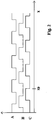
- three Hall sensors (A, B, C) are arranged in the direction of movement. These are spaced from each other regularly with a respective distance a and generate when moving the second motor part relative to the first motor part signals, which schematically in FIG. 2 are shown, the gaps are not present here. In the presence of the gaps 10, the signals of the tracks A, B, C are correspondingly long in the LOW state.
- FIG. 3 a preferred embodiment of the invention is described.
- three system of Hall sensors at regular intervals along the direction of movement are arranged one behind the other.
- the first system comprises the three Hall sensors (A1, B1, C1)
- the second system comprises the three Hall sensors (A2, B2, C2)
- the third system comprises the three Hall sensors (A3, B3, C3).
- the systems are arranged one behind the other with period length xp.
- the Hall sensor A1 has a distance xp to the Hall sensor A2.
- a continuous track signal is now generated from the fact that the signals of the Hall sensors A1, A2 and A3 are linked, wherein the result of the combination is determined by majority decision. So if the majority is at LOW level, in FIG. 4 is represented as 0, the track signal A is assigned a 0, ie LOW:
- the track signal A is assigned a 1, ie HIGH.
- the signals of the Hall sensors B1, B2 and B3 are linked to a track signal B and also the signals of the Hall sensors C1, C2 and C3 are combined to form a track signal C. In each case the majority decision is applied.
- the systems are arranged against each other at different distances, each of which amounts to an integer multiple of xp.
- the coil windings encompassed by the primary part are themselves used as magnetic field sensors, in particular using means for determining the respectively induced voltage in the windings.
- the coil windings encompassed by the primary part are themselves used as magnetic field sensors, in particular using means for determining the respectively induced voltage in the windings.
Description
Die Erfindung betrifft ein System und ein Verfahren zum Ermitteln der Position eines Motorteils.The invention relates to a system and a method for determining the position of a motor part.
Aus der
Aus der
Aus der
Aus der
Aus der
Aus der
Aus der
Aus der
Der Erfindung liegt daher die Aufgabe zugrunde, eine die Positionsermittelung bei Synchronmotoren weiterzubilden.The invention is therefore based on the object to develop a position determination in synchronous motors.
Erfindungsgemäß wird die Aufgabe bei dem System nach den in Anspruch 1 und bei dem Verfahren nach den in Anspruch 10 angegebenen Merkmalen gelöst.According to the invention the object is achieved in the system according to the features specified in
Wichtige Merkmale bei dem System sind, dass es einen Linearmotor mit Vorrichtung zum Ermitteln der Position eines ersten Motorteils umfasst, insbesondere Primärteil, relativ zu einem zweiten Motorteil, insbesondere Sekundärteil,
wobei am ersten Motorteil an mehreren Stellen Magnetfeldsensoren angeordnet sind, die auf das zweite Motorteil gerichtet sind,
wobei das zweite Motorteil in Bewegungsrichtung einen Bereich umfasst, in welchem in Bewegungsrichtung voneinander beabstandete Magnete vorgesehen sind,
wobei ein Teilbereich des Bereichs keine Magnete aufweist,
wobei die Magnete im Bereich außerhalb des Teilbereichs voneinander regelmäßig beabstandet sind mit Abstand b, insbesondere wobei die Schwerpunkte und/oder Mittelpunkte jeweils den Abstand b zum nächstbenachbarten Magneten aufweisen,
wobei die Länge des Teilbereichs in Bewegungsrichtung größer oder zumindest gleich dem Abstand b, insbesondere dem Längenwert des Abstands b, ist,
wobei mit den Magnetfeldsensoren Mittel zur Bestimmung der relativen Position des zweiten zum ersten Motorteils verbunden sind.Important features in the system are that it comprises a linear motor with a device for determining the position of a first motor part, in particular a primary part, relative to a second motor part, in particular a secondary part,
wherein magnetic field sensors are arranged at the first motor part at several points, which are directed to the second motor part,
wherein the second motor part comprises in the direction of movement a region in which magnets which are spaced apart from one another in the direction of movement are provided,
wherein a portion of the area has no magnets,
wherein the magnets in the area outside the subarea are regularly spaced from each other at a distance b, in particular wherein the center of gravity and / or center points each have the distance b to the next adjacent magnet,
wherein the length of the subarea in the direction of movement is greater than or at least equal to the distance b, in particular the length value of the distance b,
wherein means for determining the relative position of the second to the first motor part are connected to the magnetic field sensors.
Von Vorteil ist dabei, dass im Teilbereich Kopplungsvorrichtungen oder andere Vorrichtungen zwischen den das zweite Motorteil zusammensetzenden Einheiten anordenbar sind. Somit sind die Einheiten, beispielsweise Wagen, derart koppelbar, dass in Bewegungsrichtung auf die geraden linearen Bahnkurvenabschnitte folgende gekrümmte Bahnkurvenabschnitte durchfahrbar sind.The advantage here is that in the sub-area coupling devices or other devices between the second engine part composed units can be arranged. Thus, the units, for example carriages, can be coupled in such a way that following curved path curve sections can be traversed in the direction of movement on the straight linear trajectory sections.
Bei einer vorteilhaften Ausgestaltung umfassen die Mittel zur Bestimmung der relativen Position Mittel zur Mehrheitsentscheidung, die jeweils mit einer Gruppe von Sensoren verbunden sind,
wobei jeder Sensor zu einer von mindestens zwei Gruppen zugeordnet ist.In an advantageous embodiment, the means for determining the relative position comprise means for majority decision, which are each connected to a group of sensors,
wherein each sensor is associated with one of at least two groups.
Von Vorteil ist dabei, dass eine durch Lücken bewirkte Störung eliminierbar ist, indem eine entsprechend große Gruppe von Sensoren zusammen vorgesehen wird zur Erzeugung eines ungestörten Spursignals.The advantage here is that a gap caused by interference can be eliminated by a correspondingly large group of sensors is provided together to generate an undisturbed track signal.
Bei einer vorteilhaften Ausgestaltung trägt der Primärteil Wicklungen und der Sekundärteil Permanentmagnete als Magnete. Von Vorteil ist dabei, dass der Motor als Linear-Synchronmotor ausführbar ist.In an advantageous embodiment, the primary part carries windings and the secondary part permanent magnets as magnets. The advantage here is that the motor is executable as a linear synchronous motor.
Bei einer vorteilhaften Ausgestaltung ist die Länge des Teilbereichs in Bewegungsrichtung größer oder zumindest gleich dem Doppelten des Abstands b, insbesondere dem Doppelten des Längenwerts des Abstands b. Von Vorteil ist dabei, dass zwei Magnete in der regelmäßigen Anordnung von Magneten auslassbar sind und mit drei Gruppen von Messstellen mit Sensoren die bewirkten Messfehler unwirksam machbar sind.In an advantageous embodiment, the length of the subarea in the direction of movement is greater than or at least equal to twice the distance b, in particular twice the length value of the distance b. The advantage here is that two magnets in the regular arrangement of magnets can be discharged and with three groups of measuring points with sensors, the measurement errors caused are ineffective feasible.
Bei einer vorteilhaften Ausgestaltung ist wobei die Länge des Teilbereichs in Bewegungsrichtung größer oder zumindest gleich dem n-fache des Abstands b, insbesondere dem n-fachen des Längenwerts des Abstands b, wobei n eine ganze Zahl größer als 1 ist, wobei die Anzahl der Gruppen n+1 ist. Insbesondere ist die Anzahl der Magnetfeldsensoren 3 n + 3. Von Vorteil ist dabei, dass auch größere Lücken durch entsprechend größere Gruppenanzahl beherrschbar sind und ungestörte Signale zur Positionsbestimmung erzeugbar sind.In an advantageous embodiment, wherein the length of the subarea in the direction of movement is greater than or at least equal to n times the distance b, in particular n times the length value of the distance b, where n is an integer greater than 1, where the number of groups n + 1 is. In particular, the number of magnetic field sensors 3 n + 3. The advantage here is that even larger gaps can be controlled by a correspondingly larger number of groups and undisturbed signals for position determination can be generated.
Bei einer vorteilhaften Ausgestaltung umfasst das Sekundärteil eine Magnetspur, deren bewirkte Magnetfeldanteile von den Sensoren erfasst werden. Insbesondere umfasst die Magnetspur eine Lageinformations-Codierung. Von Vorteil ist dabei, dass noch höhere Genauigkeiten, insbesondere unter zusätzlicher Anwendung des Nonius-Prinzips, ermöglicht sind.In an advantageous embodiment, the secondary part comprises a magnetic track whose effected magnetic field components are detected by the sensors. In particular, the magnetic track comprises a position information coding. The advantage here is that even higher accuracies, in particular with additional application of the vernier principle, are possible.
Wichtige Merkmale der Erfindung bei dem Verfahren sind, dass zum Ermitteln der Position eines ersten Motorteils eines Elektromotors relativ zu einem zweiten Motorteil des Elektromotors vorgesehen ist,
wobei am ersten Motorteil an mehreren Stellen die von Magneten des zweiten Motorteils erzeugte oder zumindest beeinflusste Magnetfeldstärke ermittelt wird und daraus die relative Position des zweiten zum ersten Motorteil bestimmt wird,
wobei die Magnetfeldstärke an mehreren Stellen des ersten Motorteils jeweils lokal ermittelt wird, wobei die Stellen in Bewegungsrichtung voneinander beabstandet sind,
wobei jede Stelle zu einer von mindestens zwei Gruppen zugeordnet wird,
wobei durch Mehrheitsentscheidung aus den zu einer Gruppe gehörenden ermittelten Werten ein jeweiliger Signalwert bestimmt wird,
wobei aus den Signalwerten die Position bestimmt wird.Important features of the invention in the method are that is provided for determining the position of a first motor part of an electric motor relative to a second motor part of the electric motor,
wherein the magnetic field strength generated or at least influenced by magnets of the second motor part is determined at the first motor part at a plurality of locations, and the relative position of the second motor part is determined therefrom,
wherein the magnetic field strength is respectively locally determined at a plurality of locations of the first motor part, the points being spaced apart in the direction of movement,
each location being assigned to one of at least two groups,
wherein by majority decision a respective signal value is determined from the values determined belonging to a group,
where the position is determined from the signal values.
Von Vorteil ist dabei, dass das zweite Motorteil aus verschiedenen Einheiten zusammensetzbar ist, wie beispielsweise mehrere aneinander gekoppelte Wagen, Jede Einheit weist dabei beispielsweise eine regelmäßige Anordnung von Magneten auf. Jedoch sind zwischen den Wagen im Bereich der Koppelung Lücken in der Regelmäßigkeit beim Übergang zum nächsten Wagen.The advantage here is that the second motor part of different units is composable, such as several mutually coupled car, Each unit has, for example, a regular arrangement of magnets. However, between the cars in the area of the coupling gaps in the regularity in the transition to the next car.
Somit sind die Einheiten oder Wagen mit Rädern ausstattbar und somit auf gekrümmten Bahnen verfahrbar. Insbesondere bei kleinen Radien ragt das zweite Motorteil somit nur unwesentlich weit aus der Bahn heraus.Thus, the units or cars are equipped with wheels and thus movable on curved paths. In particular, with small radii, the second motor part thus protrudes only insignificantly out of the way.
Das gesamte Reaktionsteil des Linearmotors, insbesondere also das zweite Motorteil, ist also nicht zwangsweise aus einem starren Körper auszuführen sondern es ist ein gekoppelter Wagenzug verwendbar als zweites Motorteil. Im Koppelbereich der Einheiten müssen keine Magnete vorgesehen werden.The entire reaction part of the linear motor, in particular therefore the second motor part, is therefore not necessarily designed to be made of a rigid body but a coupled wagon train can be used as the second motor part. In the coupling region of the units no magnets must be provided.
Beispielsweise kann die Bahn gerade und kurvenförmige Bahnkurvenabschnitte umfassen. Der erste Motorteil ist dann vorzugsweise in geraden Bahnkurvenabschnitten angeordnet. Die Bahn ist dabei auch geschlossen ausführbar, wobei in diesem Fall der Wagenzug ebenfalls auch geschlossen ausführbar ist. Beispielsweise sind als Wagen auch Sorter einer Sorter-Anlage verwendbar.For example, the web may include straight and curved trajectory sections. The first motor part is then preferably arranged in straight trajectory sections. The train is also executable closed, in which case the wagon train is also closed executable. For example, sorters of a sorter system can also be used as wagons.
Mittels der in Gruppen zusammenfassbaren Messstellen, aus denen dann ein jeweils der jeweiligen Gruppe zugeordnetes Signal bestimmt wird, ist es ermöglicht trotz der Lücken in der Regelmäßigkeit ein von den Lücken ungestörtes Signal zu erzeugen. Hierzu dient auch der Mehrheitsentscheid. Dabei werden vorzugsweise drei Signale derart erzeugt, dass sie um 120° räumlich phasenverschoben sind. Bei Bewegung des Zweiten Motorteils mit konstanter Geschwindigkeit ergeben sich somit drei 120° zeitlich phasenverschobene Signale. Durch Beobachtung des zeitlichen Verlaufs der Signale lässt sich sogar die Bewegungsrichtung und die Bewegungsgeschwindigkeit bestimmen. Diese drei Signale sind zur Regelung der Ströme der Wicklungen des ersten Motorteils, insbesondere Primärteils, verwendbar. Dabei sind die Wicklungen entsprechend einem Drehstrommotor, insbesondere einem als lineare Ausführung abgewickelten Drehstrommotor, betreibbar. Die Signale werden also beispielsweise einer Regelschaltung eines Umrichters zugeführt, der die Wicklungen speist. Als Stellgröße der Regelschaltung dient die an die vom Umrichter jeweils an die Wicklung angelegte Spannung. Die Regelabweichung ist durch Abweichungen des Istwertes des Stromes der Wicklung vom Sollwert hierzu vorsehbar.By means of the groupable measuring points, from which a respective signal assigned to the respective group is determined, it is possible, despite the gaps in the regularity, to generate a signal undisturbed by the gaps. The majority vote also serves this purpose. In this case, preferably three signals are generated such that they are spatially out of phase by 120 °. When moving the second motor part with a constant speed, thus resulting in three 120 ° phase-shifted signals. By observing the time course of the signals, it is even possible to determine the direction of movement and the speed of movement. These three signals can be used to control the currents of the windings of the first motor part, in particular the primary part. In this case, the windings are operable in accordance with a three-phase motor, in particular a three-phase motor developed as a linear design. The signals are thus supplied, for example, to a control circuit of an inverter which feeds the windings. The manipulated variable of the control circuit is the voltage applied to the winding by the inverter. The deviation is foreseeable by deviations of the actual value of the current of the winding from the target value.
Die Magnete sind vorzugsweise derart magnetisiert, dass die Magnetisierungsrichtung quer zur Bewegungsrichtung auf das erste Motorteil hin gerichtet ist. Dabei weisen nächstbenachbarte Magnete eine jeweils umgekehrte Magnetisierungsrichtung auf.The magnets are preferably magnetized such that the magnetization direction is directed transversely to the direction of movement on the first motor part. In this case, next-adjacent magnets each have a reversed magnetization direction.
Bei einer vorteilhaften Ausgestaltung sind jeder Gruppe drei oder mehr Stellen zugeordnet. Von Vorteil ist dabei, dass zwei lückende Magnete keine Auswirkung auf die Signalverläufe haben. Somit ist eine große Lücke zischen den regelmäßigen Anordnungen vorsehbar. Vorzugsweise ist die Länge der Lücke gleich der Periodenlänge der Anordnung der Magnete.In an advantageous embodiment, each group is assigned three or more locations. The advantage here is that two gaping magnets have no effect on the waveforms. Thus, a large gap hiss the regular arrangements providable. Preferably, the length of the gap is equal to the period length of the arrangement of the magnets.
Bei einer vorteilhaften Ausgestaltung ist die Anzahl der Gruppen drei, insbesondere wobei drei Stellen jeder Gruppe zugeordnet sind. Von Vorteil ist dabei, dass zwei lückende Magnete überbrückbar sind mittels der Gruppenbildung und Mehrheitsentscheidung.In an advantageous embodiment, the number of groups is three, in particular wherein three locations are assigned to each group. The advantage here is that two lückenende magnets are bridged by grouping and majority decision.
Bei einer vorteilhaften Ausgestaltung sind die Magnete regelmäßig angeordnet. Von Vorteil ist dabei, dass eine wenig Schwankung aufweisende Vortriebskraft erzeugbar ist.In an advantageous embodiment, the magnets are arranged regularly. The advantage here is that a little fluctuation propulsion power can be generated.
Bei einer vorteilhaften Ausgestaltung sind die Stellen einer jeweiligen Gruppe jeweils regelmäßig voneinander beabstandet in Bewegungsrichtung angeordnet. Von Vorteil ist dabei, dass zwei oder mehr Sensoren in Sensorsysteme zusammenfassbar sind, wobei in Bewegungsrichtung zwei oder mehr Sensorsystem hintereinander anordenbar sind, insbesondere in regelmäßigen Abständen. Aus jedem Sensorsystem ist somit ein Sensor auswählbar, dessen Sensorsignale mit den Sensorsignalen eines entsprechenden Sensors aller anderen Sensorsysteme als Gruppe dem Mehrheitsentscheidungsmittel zuführbar ist.In an advantageous embodiment, the locations of a respective group are each arranged regularly spaced from one another in the direction of movement. The advantage here is that two or more sensors in sensor systems are summarized, with two or more sensor system can be arranged one behind the other in the direction of movement, in particular at regular intervals. From each sensor system thus a sensor is selectable, the sensor signals with the sensor signals of a corresponding sensor of all other sensor systems as a group to the majority decision means can be fed.
Bei einer vorteilhaften Ausgestaltung sind alle Stellen regelmäßig voneinander beabstandet in Bewegungsrichtung angeordnet. Von Vorteil ist dabei, dass Schwankungen der Vortriebskraft reduzierbar sind.In an advantageous embodiment, all points are regularly spaced from each other in the direction of movement. The advantage here is that fluctuations in the driving force can be reduced.
Weitere Vorteile ergeben sich aus den Unteransprüchen. Die Erfindung ist nicht auf die Merkmalskombination der Ansprüche beschränkt. Für den Fachmann ergeben sich weitere sinnvolle Kombinationsmöglichkeiten von Ansprüchen und/oder einzelnen Anspruchsmerkmalen und/oder Merkmalen der Beschreibung und/oder der Figuren, insbesondere aus der Aufgabenstellung und/oder der sich durch Vergleich mit dem Stand der Technik stellenden Aufgabe.Further advantages emerge from the subclaims. The invention is not limited to the combination of features of the claims. For the skilled person, further meaningful combination options of claims and / or individual claim features and / or features of the description and / or figures, in particular from the task and / or the task posing by comparison with the prior art arise.
- NN
- NordpolNorth Pole
- SS
- SüdpolSouth Pole
- 1010
- Lückegap
- AA
- HallsensorHall sensor
- BB
- HallsensorHall sensor
- CC
- HallsensorHall sensor
- A1A1
- HallsensorHall sensor
- B1B1
- HallsensorHall sensor
- C1C1
- HallsensorHall sensor
- A2A2
- HallsensorHall sensor
- B2B2
- HallsensorHall sensor
- C2C2
- HallsensorHall sensor
- A3A3
- HallsensorHall sensor
- B3B3
- HallsensorHall sensor
- C3C3
- HallsensorHall sensor
- xpxp
- Periodenlängeperiod length
- xx
- Bewegungsrichtungmovement direction
Die Erfindung wird nun anhand von Abbildungen näher erläutert:
- Der Motor umfasst einen ersten Motorteil, der Wicklungen umfasst zur Erzeugung eines magnetischen Wechselfeldes.
- The motor comprises a first motor part which comprises windings for generating an alternating magnetic field.
In der
Relativ unbeweglich zum ersten Motorteil sind drei Hallsensoren (A, B, C) in Bewegungsrichtung angeordnet. Diese sind voneinander regelmäßig beabstandet mit einem jeweiligen Abstand a und erzeugen beim Bewegen des zweiten Motorteils relativ zum ersten Motorteil Signale, die schematisch in
Der Abstand a beträgt vorzugsweise xp / 3 =a.The distance a is preferably xp / 3 = a.
In
Bei der Erfindung wird nun ein stetiges Spursignal daraus erzeugt, dass die Signale der Hallsensoren A1, A2 und A3 verknüpft werden, wobei das Verknüpfungsergebnis durch Mehrheitsentscheidung bestimmt wird. Wenn also die Mehrheit auf LOW-Pegel, der in
Wenn die Mehrheit der Hallsensoren A1, A2 und A3 auf HIGH-Pegel, der in
Auf diese Weise ist trotz der in
Bei weiteren vorteilhaften Ausführungsbeispielen sind die Systeme gegeneinander mit anderen Abständen angeordnet, die jeweils ein ganzzahliges Vielfaches von xp betragen.In further advantageous embodiments, the systems are arranged against each other at different distances, each of which amounts to an integer multiple of xp.
Bei weiteren vorteilhaften Ausführungsbeispielen sind die vom Primärteil umfassten Spulenwicklungen selbst als Magnetfeldsensoren verwendet, insbesondere unter Verwendung von Mitteln zur Bestimmung der in den Wicklungen jeweils induzierten Spannung. Vorteiligerweise werden somit Bauteile einsparbar.In further advantageous embodiments, the coil windings encompassed by the primary part are themselves used as magnetic field sensors, in particular using means for determining the respectively induced voltage in the windings. Advantageously, thus components can be saved.
Claims (15)
- System, comprising a linear motor with a device for determining the position of a first motor part, in particular a primary part, relative to a second motor part, in particular a secondary part,
wherein magnetic field sensors are arranged at multiple points on the first motor part and are directed towards the second motor part,
wherein the second motor part comprises in the movement direction a region in which magnets are provided, said magnets being spaced apart from one another in the movement direction, wherein a sub-region of the region has no magnets,
wherein the magnets in the region outside the sub-region are regularly spaced apart by a distance b, in particular wherein the centres of gravity and/or mid-points are each at the distance b from the next adjacent magnet,
wherein the length of the sub-region in the movement direction is greater than or at least equal to the distance b, in particular the length value of the distance b,
wherein means for determining the relative position of the second to the first motor part are connected to the magnetic field sensors. - System according to claim 1,
characterized in that
the means for determining the relative position comprise means for majority decision, which are connected in each case to a group of sensors,
wherein each sensor is assigned to one of at least two groups. - System according to any of the preceding claims,
characterized in that
the primary part carries windings and the secondary part carries permanent magnets as magnets. - System according to any of the preceding claims,
characterized in that
the motor is a linear synchronous motor. - System according to any of the preceding claims,
characterized in that
the length of the sub-region in the movement direction is greater than or at least equal to twice the distance b, in particular twice the length value of the distance b. - System according to any of the preceding claims,
characterized in that
the length of the sub-region in the movement direction is greater than or at least equal to n times the distance b, in particular n times the length value of the distance b,
wherein n is an integer greater than 1,
wherein the number of groups is n+1. - System according to any of the preceding claims,
characterized in that
the number of magnetic field sensors is 3n+3. - System according to any of the preceding claims,
characterized in that
the secondary part comprises a magnetic track, and the magnetic field components brought about thereby are detected by the sensors. - System according to any of the preceding claims,
characterized in that
the magnetic track comprises position information coding, and/or in that
the coil windings which the primary part comprises are themselves used as magnetic field sensors, in particular using means for determining the voltage induced in each case in the windings. - Method for determining the position of a first motor part of an electric motor relative to a second motor part of the electric motor in a system according to any of the preceding claims,
wherein the magnetic field strength generated or at least influenced by magnets of the second motor part is determined at multiple points on the first motor part and the relative position of the second to the first motor part is determined therefrom,
characterized in that
the magnetic field strength is in each case determined locally at multiple points on the first motor part, wherein the points are spaced apart from one another in the movement direction, wherein each point is assigned to one of at least two groups, wherein a respective signal value is determined by majority decision from the determined values belonging to one group, wherein the position is determined from the signal values. - Method according to claim 10,
characterized in that
three or more points are assigned to each group. - Method according to any of claims 10 to 11,
characterized in that
the number of groups is three, in particular wherein three points are assigned to each group. - Method according to any of claims 10 to 12,
characterized in that
the magnets are arranged regularly. - Method according to any of claims 10 to 13,
characterized in that
the points of a respective group are in each case arranged regularly spaced apart from one another in the movement direction. - Method according to any of claims 10 to 14,
characterized in that
all points are arranged regularly spaced apart from one another in the movement direction.
Applications Claiming Priority (2)
| Application Number | Priority Date | Filing Date | Title |
|---|---|---|---|
| DE102007006807 | 2007-02-07 | ||
| EP08701147A EP2115396B1 (en) | 2007-02-07 | 2008-01-18 | Method and system for determining the position of a motor part |
Related Parent Applications (2)
| Application Number | Title | Priority Date | Filing Date |
|---|---|---|---|
| EP08701147A Division EP2115396B1 (en) | 2007-02-07 | 2008-01-18 | Method and system for determining the position of a motor part |
| EP08701147.4 Division | 2008-01-18 |
Publications (3)
| Publication Number | Publication Date |
|---|---|
| EP2228629A2 EP2228629A2 (en) | 2010-09-15 |
| EP2228629A3 EP2228629A3 (en) | 2012-05-30 |
| EP2228629B1 true EP2228629B1 (en) | 2017-07-26 |
Family
ID=39628311
Family Applications (2)
| Application Number | Title | Priority Date | Filing Date |
|---|---|---|---|
| EP08701147A Active EP2115396B1 (en) | 2007-02-07 | 2008-01-18 | Method and system for determining the position of a motor part |
| EP10006476.5A Active EP2228629B1 (en) | 2007-02-07 | 2008-01-18 | Method and system for determining the position of a motor part |
Family Applications Before (1)
| Application Number | Title | Priority Date | Filing Date |
|---|---|---|---|
| EP08701147A Active EP2115396B1 (en) | 2007-02-07 | 2008-01-18 | Method and system for determining the position of a motor part |
Country Status (5)
| Country | Link |
|---|---|
| EP (2) | EP2115396B1 (en) |
| CN (1) | CN101589295B (en) |
| DE (1) | DE102008006305B4 (en) |
| DK (1) | DK2228629T3 (en) |
| WO (1) | WO2008095595A2 (en) |
Families Citing this family (12)
| Publication number | Priority date | Publication date | Assignee | Title |
|---|---|---|---|---|
| FI20095986A0 (en) * | 2009-09-25 | 2009-09-25 | Kone Corp | Measuring system, electric drive and elevator system |
| JP5013146B2 (en) | 2009-12-03 | 2012-08-29 | Tdk株式会社 | Magnetic position detector |
| WO2012107159A2 (en) | 2011-02-07 | 2012-08-16 | Sew-Eurodrive Gmbh & Co. Kg | Sorting system |
| DE102012209399A1 (en) * | 2012-06-04 | 2013-12-05 | Intrasys Gmbh Innovative Transportsysteme | Use of an electromagnetic speed change device, such as linear motor and / or eddy current brake, for speed measurement |
| JP6314372B2 (en) * | 2013-04-22 | 2018-04-25 | 村田機械株式会社 | POSITION DETECTION DEVICE, POSITION DETECTION METHOD, AND MOBILE BODY SYSTEM |
| CN103557782B (en) * | 2013-10-16 | 2016-04-20 | 清华大学 | A kind of linear electric motors localization method based on switch Hall sensor sequential encoding |
| US10377582B2 (en) | 2015-06-24 | 2019-08-13 | Beumer Group A/S | Line sorter |
| JP6191665B2 (en) * | 2015-08-21 | 2017-09-06 | 村田機械株式会社 | Moving body |
| JP6225961B2 (en) * | 2015-08-21 | 2017-11-08 | 村田機械株式会社 | Moving body |
| SG11201801002VA (en) * | 2015-08-21 | 2018-03-28 | Murata Machinery Ltd | Mobile body |
| CN107966094A (en) * | 2017-11-17 | 2018-04-27 | 山东大东联石油设备有限公司 | A kind of oil well pump displacement detection device for being placed in underground installation |
| CN110107869A (en) * | 2019-05-09 | 2019-08-09 | 广州星迪智能光电科技有限公司 | A kind of stage lighting Quick reset device and method |
Family Cites Families (11)
| Publication number | Priority date | Publication date | Assignee | Title |
|---|---|---|---|---|
| US4897603A (en) | 1988-02-29 | 1990-01-30 | Siemens Aktiengesellschaft | Arrangement for determining the speed and rotor position of an electric machine |
| JP2648181B2 (en) | 1988-08-31 | 1997-08-27 | オ−クマ株式会社 | Linear encoder |
| DE4213380A1 (en) | 1992-04-23 | 1993-10-28 | Swf Auto Electric Gmbh | Electronically commutated brushless DC motor with permanent magnets - has circumferential dimension of each rotor magnet equal to sum of breadths of adjacent stator tooth pole piece and gap |
| US5434504A (en) * | 1993-10-01 | 1995-07-18 | International Business Machines Corporation | Position sensors for linear motors including plural symmetrical fluxes generated by a planar drive coil and received by planar sense coils being colinear along an axis of motion |
| US5742136A (en) | 1994-09-20 | 1998-04-21 | Yokogawa Electric Corporation | Linear motor drive system |
| DE10135540B4 (en) | 2001-07-20 | 2007-03-15 | Siemens Ag | Method for controlling electric motors |
| DE10161227A1 (en) * | 2001-12-13 | 2003-07-03 | Heidenhain Gmbh Dr Johannes | Synchronous motor position/speed measurement device has primary part with drive coils, secondary part with magnets, two position measurement systems, two evaluation units and a comparator |
| US7095193B2 (en) * | 2004-05-19 | 2006-08-22 | Hr Textron, Inc. | Brushless DC motors with remote Hall sensing and methods of making the same |
| JP4478537B2 (en) | 2004-09-03 | 2010-06-09 | 日本ビクター株式会社 | Brushless motor |
| US7259553B2 (en) | 2005-04-13 | 2007-08-21 | Sri International | System and method of magnetically sensing position of a moving component |
| DE102006028794A1 (en) | 2005-07-02 | 2007-01-11 | Milan Marinkovic | Carriage distance sensor for machine use has chain of pole fields on measurement strip with digital sensor on carriage |
-
2008
- 2008-01-18 WO PCT/EP2008/000363 patent/WO2008095595A2/en active Application Filing
- 2008-01-18 DK DK10006476.5T patent/DK2228629T3/en active
- 2008-01-18 EP EP08701147A patent/EP2115396B1/en active Active
- 2008-01-18 CN CN2008800032221A patent/CN101589295B/en active Active
- 2008-01-18 EP EP10006476.5A patent/EP2228629B1/en active Active
- 2008-01-26 DE DE102008006305.3A patent/DE102008006305B4/en active Active
Non-Patent Citations (1)
| Title |
|---|
| None * |
Also Published As
| Publication number | Publication date |
|---|---|
| EP2228629A2 (en) | 2010-09-15 |
| EP2115396B1 (en) | 2013-03-13 |
| DE102008006305B4 (en) | 2022-02-17 |
| WO2008095595A3 (en) | 2009-03-05 |
| EP2228629A3 (en) | 2012-05-30 |
| EP2115396A2 (en) | 2009-11-11 |
| WO2008095595A2 (en) | 2008-08-14 |
| CN101589295A (en) | 2009-11-25 |
| DE102008006305A1 (en) | 2008-08-21 |
| CN101589295B (en) | 2011-07-13 |
| DK2228629T3 (en) | 2017-11-06 |
Similar Documents
| Publication | Publication Date | Title |
|---|---|---|
| EP2228629B1 (en) | Method and system for determining the position of a motor part | |
| EP3376166B1 (en) | Method for determining the absolution position of a runner of a linear motor | |
| EP1729993B1 (en) | Device for the generation of reliable status signals of a vehicle that is movable along a given path of travel | |
| EP2884639B1 (en) | Linear transport system | |
| EP2831549B1 (en) | Position detection device and method for detecting a position of a movable element in a drive device | |
| EP2061672B1 (en) | Method and arrangement for measuring a gap | |
| DE102006056335A1 (en) | Magnetic levitation vehicle with at least one magnet system | |
| DE102013218768A1 (en) | Inductive position measuring device | |
| DE102010028333A1 (en) | Incremental multi-position detection system for a circulating electromagnetic transfer system | |
| DE102013108767A1 (en) | Decentralized linear motor control for transport systems | |
| WO2006100057A1 (en) | Linear motor and method for operation of a linear motor | |
| WO2008019988A1 (en) | Electric motor with measuring system for positions or movements | |
| EP2325039A2 (en) | Sensor system for transport assemblies with linear synchronous drive and transport assembly | |
| EP2869035B1 (en) | Position measuring system and control method for linear motors linked together | |
| DE102013000852B4 (en) | Rail transportation system and method of operating a rail transportation system | |
| DE102009003080A1 (en) | Position detection arrangement for a circulating transfer system | |
| WO2019101544A1 (en) | Lift system having a signal generation unit arranged on a lift car of the lift system | |
| DE102017222402B4 (en) | Angle of rotation measuring device | |
| EP2797802B1 (en) | Sensor device for detecting a wheel which moves along a travel rail | |
| EP1985345A1 (en) | Method and device for determining the velocity of rides | |
| DE10135540A1 (en) | Measurement device for determining position and velocity of the moving part of a linear electric motor relative to a stationary part, for use in motor control, by measuring the varying field strength of fixed magnets | |
| DE102006006213A1 (en) | Synchronous linear motor operating method for use in vehicle, involves determining current directly or indirectly by coil, and determining induced voltage from measured values for current and voltage using parameters indicated by machine | |
| DE102012000680A1 (en) | sorter | |
| EP3429071A1 (en) | Location of a secondary part when used in a linear motor based system | |
| DE102019218729A1 (en) | Detection device for detecting rotational movement information of a rotating component of a drive train of a motor vehicle |
Legal Events
| Date | Code | Title | Description |
|---|---|---|---|
| PUAI | Public reference made under article 153(3) epc to a published international application that has entered the european phase |
Free format text: ORIGINAL CODE: 0009012 |
|
| AC | Divisional application: reference to earlier application |
Ref document number: 2115396 Country of ref document: EP Kind code of ref document: P |
|
| AK | Designated contracting states |
Kind code of ref document: A2 Designated state(s): AT BE BG CH CY CZ DE DK EE ES FI FR GB GR HR HU IE IS IT LI LT LU LV MC MT NL NO PL PT RO SE SI SK TR |
|
| 17P | Request for examination filed |
Effective date: 20100622 |
|
| PUAL | Search report despatched |
Free format text: ORIGINAL CODE: 0009013 |
|
| RIC1 | Information provided on ipc code assigned before grant |
Ipc: H02K 11/00 20060101ALI20120420BHEP Ipc: H02P 5/52 20060101ALI20120420BHEP Ipc: H02P 6/04 20060101ALI20120420BHEP Ipc: H02K 29/08 20060101ALI20120420BHEP Ipc: G01D 5/252 20060101AFI20120420BHEP Ipc: G01D 5/14 20060101ALI20120420BHEP Ipc: G01D 5/249 20060101ALI20120420BHEP Ipc: G01D 5/244 20060101ALI20120420BHEP |
|
| AK | Designated contracting states |
Kind code of ref document: A3 Designated state(s): AT BE BG CH CY CZ DE DK EE ES FI FR GB GR HR HU IE IS IT LI LT LU LV MC MT NL NO PL PT RO SE SI SK TR |
|
| GRAP | Despatch of communication of intention to grant a patent |
Free format text: ORIGINAL CODE: EPIDOSNIGR1 |
|
| RIC1 | Information provided on ipc code assigned before grant |
Ipc: H02P 5/52 20160101ALI20170201BHEP Ipc: H02K 29/08 20060101ALI20170201BHEP Ipc: H02K 11/00 20160101ALI20170201BHEP Ipc: G01D 5/249 20060101ALI20170201BHEP Ipc: G01D 5/252 20060101AFI20170201BHEP Ipc: H02K 11/215 20160101ALI20170201BHEP Ipc: H02P 6/04 20160101ALI20170201BHEP Ipc: G01D 5/244 20060101ALI20170201BHEP Ipc: G01D 5/14 20060101ALI20170201BHEP |
|
| INTG | Intention to grant announced |
Effective date: 20170303 |
|
| GRAS | Grant fee paid |
Free format text: ORIGINAL CODE: EPIDOSNIGR3 |
|
| GRAA | (expected) grant |
Free format text: ORIGINAL CODE: 0009210 |
|
| AC | Divisional application: reference to earlier application |
Ref document number: 2115396 Country of ref document: EP Kind code of ref document: P |
|
| AK | Designated contracting states |
Kind code of ref document: B1 Designated state(s): AT BE BG CH CY CZ DE DK EE ES FI FR GB GR HR HU IE IS IT LI LT LU LV MC MT NL NO PL PT RO SE SI SK TR |
|
| REG | Reference to a national code |
Ref country code: GB Ref legal event code: FG4D Free format text: NOT ENGLISH |
|
| REG | Reference to a national code |
Ref country code: CH Ref legal event code: EP Ref country code: CH Ref legal event code: NV Representative=s name: HEPP WENGER RYFFEL AG, CH |
|
| REG | Reference to a national code |
Ref country code: AT Ref legal event code: REF Ref document number: 912742 Country of ref document: AT Kind code of ref document: T Effective date: 20170815 |
|
| REG | Reference to a national code |
Ref country code: IE Ref legal event code: FG4D Free format text: LANGUAGE OF EP DOCUMENT: GERMAN |
|
| REG | Reference to a national code |
Ref country code: DE Ref legal event code: R096 Ref document number: 502008015487 Country of ref document: DE |
|
| REG | Reference to a national code |
Ref country code: DK Ref legal event code: T3 Effective date: 20171101 |
|
| REG | Reference to a national code |
Ref country code: NL Ref legal event code: MP Effective date: 20170726 |
|
| REG | Reference to a national code |
Ref country code: LT Ref legal event code: MG4D Ref country code: FR Ref legal event code: PLFP Year of fee payment: 11 |
|
| PG25 | Lapsed in a contracting state [announced via postgrant information from national office to epo] |
Ref country code: HR Free format text: LAPSE BECAUSE OF FAILURE TO SUBMIT A TRANSLATION OF THE DESCRIPTION OR TO PAY THE FEE WITHIN THE PRESCRIBED TIME-LIMIT Effective date: 20170726 Ref country code: LT Free format text: LAPSE BECAUSE OF FAILURE TO SUBMIT A TRANSLATION OF THE DESCRIPTION OR TO PAY THE FEE WITHIN THE PRESCRIBED TIME-LIMIT Effective date: 20170726 Ref country code: FI Free format text: LAPSE BECAUSE OF FAILURE TO SUBMIT A TRANSLATION OF THE DESCRIPTION OR TO PAY THE FEE WITHIN THE PRESCRIBED TIME-LIMIT Effective date: 20170726 Ref country code: NL Free format text: LAPSE BECAUSE OF FAILURE TO SUBMIT A TRANSLATION OF THE DESCRIPTION OR TO PAY THE FEE WITHIN THE PRESCRIBED TIME-LIMIT Effective date: 20170726 Ref country code: SE Free format text: LAPSE BECAUSE OF FAILURE TO SUBMIT A TRANSLATION OF THE DESCRIPTION OR TO PAY THE FEE WITHIN THE PRESCRIBED TIME-LIMIT Effective date: 20170726 Ref country code: NO Free format text: LAPSE BECAUSE OF FAILURE TO SUBMIT A TRANSLATION OF THE DESCRIPTION OR TO PAY THE FEE WITHIN THE PRESCRIBED TIME-LIMIT Effective date: 20171026 |
|
| PG25 | Lapsed in a contracting state [announced via postgrant information from national office to epo] |
Ref country code: IS Free format text: LAPSE BECAUSE OF FAILURE TO SUBMIT A TRANSLATION OF THE DESCRIPTION OR TO PAY THE FEE WITHIN THE PRESCRIBED TIME-LIMIT Effective date: 20171126 Ref country code: LV Free format text: LAPSE BECAUSE OF FAILURE TO SUBMIT A TRANSLATION OF THE DESCRIPTION OR TO PAY THE FEE WITHIN THE PRESCRIBED TIME-LIMIT Effective date: 20170726 Ref country code: BG Free format text: LAPSE BECAUSE OF FAILURE TO SUBMIT A TRANSLATION OF THE DESCRIPTION OR TO PAY THE FEE WITHIN THE PRESCRIBED TIME-LIMIT Effective date: 20171026 Ref country code: PL Free format text: LAPSE BECAUSE OF FAILURE TO SUBMIT A TRANSLATION OF THE DESCRIPTION OR TO PAY THE FEE WITHIN THE PRESCRIBED TIME-LIMIT Effective date: 20170726 Ref country code: ES Free format text: LAPSE BECAUSE OF FAILURE TO SUBMIT A TRANSLATION OF THE DESCRIPTION OR TO PAY THE FEE WITHIN THE PRESCRIBED TIME-LIMIT Effective date: 20170726 Ref country code: GR Free format text: LAPSE BECAUSE OF FAILURE TO SUBMIT A TRANSLATION OF THE DESCRIPTION OR TO PAY THE FEE WITHIN THE PRESCRIBED TIME-LIMIT Effective date: 20171027 |
|
| PG25 | Lapsed in a contracting state [announced via postgrant information from national office to epo] |
Ref country code: RO Free format text: LAPSE BECAUSE OF FAILURE TO SUBMIT A TRANSLATION OF THE DESCRIPTION OR TO PAY THE FEE WITHIN THE PRESCRIBED TIME-LIMIT Effective date: 20170726 Ref country code: CZ Free format text: LAPSE BECAUSE OF FAILURE TO SUBMIT A TRANSLATION OF THE DESCRIPTION OR TO PAY THE FEE WITHIN THE PRESCRIBED TIME-LIMIT Effective date: 20170726 |
|
| REG | Reference to a national code |
Ref country code: DE Ref legal event code: R097 Ref document number: 502008015487 Country of ref document: DE |
|
| PG25 | Lapsed in a contracting state [announced via postgrant information from national office to epo] |
Ref country code: SK Free format text: LAPSE BECAUSE OF FAILURE TO SUBMIT A TRANSLATION OF THE DESCRIPTION OR TO PAY THE FEE WITHIN THE PRESCRIBED TIME-LIMIT Effective date: 20170726 Ref country code: EE Free format text: LAPSE BECAUSE OF FAILURE TO SUBMIT A TRANSLATION OF THE DESCRIPTION OR TO PAY THE FEE WITHIN THE PRESCRIBED TIME-LIMIT Effective date: 20170726 |
|
| PLBE | No opposition filed within time limit |
Free format text: ORIGINAL CODE: 0009261 |
|
| STAA | Information on the status of an ep patent application or granted ep patent |
Free format text: STATUS: NO OPPOSITION FILED WITHIN TIME LIMIT |
|
| 26N | No opposition filed |
Effective date: 20180430 |
|
| PG25 | Lapsed in a contracting state [announced via postgrant information from national office to epo] |
Ref country code: SI Free format text: LAPSE BECAUSE OF FAILURE TO SUBMIT A TRANSLATION OF THE DESCRIPTION OR TO PAY THE FEE WITHIN THE PRESCRIBED TIME-LIMIT Effective date: 20170726 |
|
| PG25 | Lapsed in a contracting state [announced via postgrant information from national office to epo] |
Ref country code: MT Free format text: LAPSE BECAUSE OF FAILURE TO SUBMIT A TRANSLATION OF THE DESCRIPTION OR TO PAY THE FEE WITHIN THE PRESCRIBED TIME-LIMIT Effective date: 20170726 |
|
| PG25 | Lapsed in a contracting state [announced via postgrant information from national office to epo] |
Ref country code: LU Free format text: LAPSE BECAUSE OF NON-PAYMENT OF DUE FEES Effective date: 20180118 |
|
| REG | Reference to a national code |
Ref country code: IE Ref legal event code: MM4A |
|
| REG | Reference to a national code |
Ref country code: BE Ref legal event code: MM Effective date: 20180131 |
|
| PG25 | Lapsed in a contracting state [announced via postgrant information from national office to epo] |
Ref country code: BE Free format text: LAPSE BECAUSE OF NON-PAYMENT OF DUE FEES Effective date: 20180131 |
|
| PG25 | Lapsed in a contracting state [announced via postgrant information from national office to epo] |
Ref country code: IE Free format text: LAPSE BECAUSE OF NON-PAYMENT OF DUE FEES Effective date: 20180118 |
|
| PG25 | Lapsed in a contracting state [announced via postgrant information from national office to epo] |
Ref country code: MC Free format text: LAPSE BECAUSE OF FAILURE TO SUBMIT A TRANSLATION OF THE DESCRIPTION OR TO PAY THE FEE WITHIN THE PRESCRIBED TIME-LIMIT Effective date: 20170726 |
|
| PG25 | Lapsed in a contracting state [announced via postgrant information from national office to epo] |
Ref country code: TR Free format text: LAPSE BECAUSE OF FAILURE TO SUBMIT A TRANSLATION OF THE DESCRIPTION OR TO PAY THE FEE WITHIN THE PRESCRIBED TIME-LIMIT Effective date: 20170726 |
|
| PG25 | Lapsed in a contracting state [announced via postgrant information from national office to epo] |
Ref country code: PT Free format text: LAPSE BECAUSE OF FAILURE TO SUBMIT A TRANSLATION OF THE DESCRIPTION OR TO PAY THE FEE WITHIN THE PRESCRIBED TIME-LIMIT Effective date: 20170726 Ref country code: HU Free format text: LAPSE BECAUSE OF FAILURE TO SUBMIT A TRANSLATION OF THE DESCRIPTION OR TO PAY THE FEE WITHIN THE PRESCRIBED TIME-LIMIT; INVALID AB INITIO Effective date: 20080118 |
|
| PG25 | Lapsed in a contracting state [announced via postgrant information from national office to epo] |
Ref country code: CY Free format text: LAPSE BECAUSE OF FAILURE TO SUBMIT A TRANSLATION OF THE DESCRIPTION OR TO PAY THE FEE WITHIN THE PRESCRIBED TIME-LIMIT Effective date: 20170726 |
|
| PGFP | Annual fee paid to national office [announced via postgrant information from national office to epo] |
Ref country code: DK Payment date: 20230111 Year of fee payment: 16 Ref country code: CH Payment date: 20230330 Year of fee payment: 16 Ref country code: AT Payment date: 20230111 Year of fee payment: 16 |
|
| PGFP | Annual fee paid to national office [announced via postgrant information from national office to epo] |
Ref country code: IT Payment date: 20221213 Year of fee payment: 16 Ref country code: DE Payment date: 20230131 Year of fee payment: 16 |
|
| PGFP | Annual fee paid to national office [announced via postgrant information from national office to epo] |
Ref country code: GB Payment date: 20231130 Year of fee payment: 17 |
|
| PGFP | Annual fee paid to national office [announced via postgrant information from national office to epo] |
Ref country code: FR Payment date: 20231212 Year of fee payment: 17 |