EP2228524A2 - Low heating value fuel gas blending control - Google Patents
Low heating value fuel gas blending control Download PDFInfo
- Publication number
- EP2228524A2 EP2228524A2 EP10155884A EP10155884A EP2228524A2 EP 2228524 A2 EP2228524 A2 EP 2228524A2 EP 10155884 A EP10155884 A EP 10155884A EP 10155884 A EP10155884 A EP 10155884A EP 2228524 A2 EP2228524 A2 EP 2228524A2
- Authority
- EP
- European Patent Office
- Prior art keywords
- fuel
- gas
- heating value
- mixed
- flow rate
- Prior art date
- Legal status (The legal status is an assumption and is not a legal conclusion. Google has not performed a legal analysis and makes no representation as to the accuracy of the status listed.)
- Granted
Links
Images


Classifications
-
- F—MECHANICAL ENGINEERING; LIGHTING; HEATING; WEAPONS; BLASTING
- F02—COMBUSTION ENGINES; HOT-GAS OR COMBUSTION-PRODUCT ENGINE PLANTS
- F02C—GAS-TURBINE PLANTS; AIR INTAKES FOR JET-PROPULSION PLANTS; CONTROLLING FUEL SUPPLY IN AIR-BREATHING JET-PROPULSION PLANTS
- F02C9/00—Controlling gas-turbine plants; Controlling fuel supply in air- breathing jet-propulsion plants
- F02C9/26—Control of fuel supply
- F02C9/40—Control of fuel supply specially adapted to the use of a special fuel or a plurality of fuels
-
- C—CHEMISTRY; METALLURGY
- C10—PETROLEUM, GAS OR COKE INDUSTRIES; TECHNICAL GASES CONTAINING CARBON MONOXIDE; FUELS; LUBRICANTS; PEAT
- C10K—PURIFYING OR MODIFYING THE CHEMICAL COMPOSITION OF COMBUSTIBLE GASES CONTAINING CARBON MONOXIDE
- C10K3/00—Modifying the chemical composition of combustible gases containing carbon monoxide to produce an improved fuel, e.g. one of different calorific value, which may be free from carbon monoxide
- C10K3/06—Modifying the chemical composition of combustible gases containing carbon monoxide to produce an improved fuel, e.g. one of different calorific value, which may be free from carbon monoxide by mixing with gases
-
- F—MECHANICAL ENGINEERING; LIGHTING; HEATING; WEAPONS; BLASTING
- F02—COMBUSTION ENGINES; HOT-GAS OR COMBUSTION-PRODUCT ENGINE PLANTS
- F02C—GAS-TURBINE PLANTS; AIR INTAKES FOR JET-PROPULSION PLANTS; CONTROLLING FUEL SUPPLY IN AIR-BREATHING JET-PROPULSION PLANTS
- F02C3/00—Gas-turbine plants characterised by the use of combustion products as the working fluid
- F02C3/20—Gas-turbine plants characterised by the use of combustion products as the working fluid using a special fuel, oxidant, or dilution fluid to generate the combustion products
- F02C3/26—Gas-turbine plants characterised by the use of combustion products as the working fluid using a special fuel, oxidant, or dilution fluid to generate the combustion products the fuel or oxidant being solid or pulverulent, e.g. in slurry or suspension
- F02C3/28—Gas-turbine plants characterised by the use of combustion products as the working fluid using a special fuel, oxidant, or dilution fluid to generate the combustion products the fuel or oxidant being solid or pulverulent, e.g. in slurry or suspension using a separate gas producer for gasifying the fuel before combustion
-
- F—MECHANICAL ENGINEERING; LIGHTING; HEATING; WEAPONS; BLASTING
- F02—COMBUSTION ENGINES; HOT-GAS OR COMBUSTION-PRODUCT ENGINE PLANTS
- F02C—GAS-TURBINE PLANTS; AIR INTAKES FOR JET-PROPULSION PLANTS; CONTROLLING FUEL SUPPLY IN AIR-BREATHING JET-PROPULSION PLANTS
- F02C9/00—Controlling gas-turbine plants; Controlling fuel supply in air- breathing jet-propulsion plants
- F02C9/26—Control of fuel supply
-
- F—MECHANICAL ENGINEERING; LIGHTING; HEATING; WEAPONS; BLASTING
- F05—INDEXING SCHEMES RELATING TO ENGINES OR PUMPS IN VARIOUS SUBCLASSES OF CLASSES F01-F04
- F05D—INDEXING SCHEME FOR ASPECTS RELATING TO NON-POSITIVE-DISPLACEMENT MACHINES OR ENGINES, GAS-TURBINES OR JET-PROPULSION PLANTS
- F05D2220/00—Application
- F05D2220/70—Application in combination with
- F05D2220/75—Application in combination with equipment using fuel having a low calorific value, e.g. low BTU fuel, waste end, syngas, biomass fuel or flare gas
-
- Y—GENERAL TAGGING OF NEW TECHNOLOGICAL DEVELOPMENTS; GENERAL TAGGING OF CROSS-SECTIONAL TECHNOLOGIES SPANNING OVER SEVERAL SECTIONS OF THE IPC; TECHNICAL SUBJECTS COVERED BY FORMER USPC CROSS-REFERENCE ART COLLECTIONS [XRACs] AND DIGESTS
- Y02—TECHNOLOGIES OR APPLICATIONS FOR MITIGATION OR ADAPTATION AGAINST CLIMATE CHANGE
- Y02E—REDUCTION OF GREENHOUSE GAS [GHG] EMISSIONS, RELATED TO ENERGY GENERATION, TRANSMISSION OR DISTRIBUTION
- Y02E20/00—Combustion technologies with mitigation potential
- Y02E20/16—Combined cycle power plant [CCPP], or combined cycle gas turbine [CCGT]
-
- Y—GENERAL TAGGING OF NEW TECHNOLOGICAL DEVELOPMENTS; GENERAL TAGGING OF CROSS-SECTIONAL TECHNOLOGIES SPANNING OVER SEVERAL SECTIONS OF THE IPC; TECHNICAL SUBJECTS COVERED BY FORMER USPC CROSS-REFERENCE ART COLLECTIONS [XRACs] AND DIGESTS
- Y02—TECHNOLOGIES OR APPLICATIONS FOR MITIGATION OR ADAPTATION AGAINST CLIMATE CHANGE
- Y02E—REDUCTION OF GREENHOUSE GAS [GHG] EMISSIONS, RELATED TO ENERGY GENERATION, TRANSMISSION OR DISTRIBUTION
- Y02E50/00—Technologies for the production of fuel of non-fossil origin
- Y02E50/10—Biofuels, e.g. bio-diesel
Definitions
- the fuel gas system 64 may receive and further process fuel gas sources from other processes to generate the fuel gas 66 used by the gas turbine 12.
- the fuel gas system 64 may receive fuel gas sources generated by a steel mill.
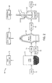
- FIG. 2 is a process flow diagram of an embodiment of a steel mill 68 which may generate fuel gas sources for use within the fuel gas system 64. Steel production processes of the steel mill 68 typically generate large volumes of specialty gases as by-products.
- blast furnace gas 84 although generally having the lowest LHV, is the most abundant of the by-product gases generated by the steel mill 68.
- coke oven gas 76 is a higher quality gas, it is also usually available in smaller amounts.
- an adjusted value of the second characteristic of the second gas may be determined by comparing the correction factor (from step 220) to the predicted value (from step 222).
- an adjusted value of the flow rate of the coke oven gas 76 may be determined based on a correction needed to meet the target LHV of the fuel gas 66 mixture.
- the second characteristic of the second gas may be adjusted based on the adjusted value determined in step 224.
- the flow rate of the coke oven gas 76 may be adjusted by modulating the flow control valve 120 of FIG. 4 based on the adjusted value.
Landscapes
- Engineering & Computer Science (AREA)
- Chemical & Material Sciences (AREA)
- Combustion & Propulsion (AREA)
- Mechanical Engineering (AREA)
- General Engineering & Computer Science (AREA)
- Chemical Kinetics & Catalysis (AREA)
- General Chemical & Material Sciences (AREA)
- Oil, Petroleum & Natural Gas (AREA)
- Organic Chemistry (AREA)
- Engine Equipment That Uses Special Cycles (AREA)
- Regulation And Control Of Combustion (AREA)
Abstract
Description
- The subject matter disclosed herein relates to blending control of fuel gases and, more particularly, to blending control of by-product gases received from a steel mill.
- The production of steel via conventional blast furnaces results in the generation of large quantities of blast furnace gas, which is generally characterized by a lower heating value than typical fuel gases. Therefore, despite its relative abundance, blast furnace gas is generally unsuitable for use as a fuel source in combustion-driven equipment, such as gas turbines. However, coke oven gas is a second by-product gas generated during the production of steel. Coke oven gas is generally characterized by a higher heating value than typical fuel gases, but is generally available in much smaller quantities than blast furnace gas. As such, neither of these by-product gases from the production of steel are, by themselves, suitable as fuel gas sources.
- Certain embodiments commensurate in scope with the originally claimed invention are summarized below. These embodiments are not intended to limit the scope of the claimed invention, but rather these embodiments are intended only to provide a brief summary of possible forms of the invention. Indeed, the invention may encompass a variety of forms that may be similar to or different from the embodiments set forth below.
- In a first embodiment, a system includes a fuel system. The fuel system includes a fuel blending system configured to blend a first fuel with a second fuel in a ratio to produce a third mixed fuel. The first fuel has a first heating value, the second fuel has a second heating value, and the third mixed fuel has a third heating value. In addition, the first heating value is lower than the second heating value. The fuel system also includes a feedforward controller configured to adjust the ratio of the first and second fuels to correct the third heating value.
- In a second embodiment, a system includes a turbine fuel blending controller. The turbine fuel blending controller includes a feedforward control logic configured to predict a fuel flow rate of a first fuel and/or a second fuel being mixed to provide a third mixed fuel. The first and second fuels have different heating values from one another. In addition, the turbine fuel blending controller includes a feedback control logic configured to correct the fuel flow rate based at least in part on a comparison between the target heating value and a measured heating value of the third mixed fuel.
- In a third embodiment, a method includes blending a first fuel with a second fuel in a ratio to produce a third mixed fuel. The first fuel has a first heating value, the second fuel has a second heating value, and the third mixed fuel has a third heating value. In addition, the first heating value is different than the second heating value. The method also includes feedforward controlling the third heating value of the third mixed fuel via prediction and correction of a fuel flow rate of the first and/or second fuels to adjust the ratio of the first and second fuels based at least in part on a comparison between a measurement and a target for the third heating value.
- There follows a detailed description of embodiments of the invention by way of example only with reference to the accompanying drawings, in which:
-
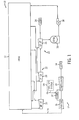
FIG. 1 is a schematic flow diagram of an embodiment of a combined cycle power generation system having a gas turbine, a steam turbine, a heat recovery steam generation system, and a fuel gas system; -
FIG. 2 is a process flow diagram of an embodiment of a steel mill which may generate fuel gas sources for use within the fuel gas system; -
FIG. 3 is a process flow diagram of an embodiment of the fuel gas system, which includes a fuel gas cleanup and blending system, a fuel gas compression system, and a fuel gas control module; -
FIG. 4 is a schematic flow diagram of an embodiment of the fuel gas cleanup and blending system of the fuel gas system ofFIG. 3 ; -
FIG. 5 is a schematic flow diagram of an embodiment of the fuel gas compression system of the fuel gas system ofFIG. 3 ; -
FIG. 6 is a schematic flow diagram of an embodiment of the fuel gas control module of the fuel gas system ofFIG. 3 ; -
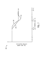
FIG. 7 is a chart depicting a target LHV schedule and measured LHV of the fuel gas during loading from fuel transfer to a base load of the gas turbine; -
FIG. 8 is an embodiment of controller logic used by the controller of the fuel gas system ofFIG. 3 ; -
FIG. 9 is a chart depicting the target LHV schedule ofFIG. 7 with measured LHV of the fuel gas during loading from fuel transfer to base load of the gas turbine, utilizing the controller logic ofFIG. 8 ; and -
FIG. 10 is a flow chart of an embodiment of a method for controlling the blending of gases, utilizing the controller logic ofFIG. 8 . - One or more specific embodiments of the present invention will be described below. In an effort to provide a concise description of these embodiments, all features of an actual implementation may not be described in the specification. It should be appreciated that in the development of any such actual implementation, as in any engineering or design project, numerous implementation-specific decisions must be made to achieve the developers' specific goals, such as compliance with system-related and business-related constraints, which may vary from one implementation to another. Moreover, it should be appreciated that such a development effort might be complex and time consuming, but would nevertheless be a routine undertaking of design, fabrication, and manufacture for those of ordinary skill having the benefit of this disclosure.
- When introducing elements of various embodiments of the present invention, the articles "a," "an," "the," and "said" are intended to mean that there are one or more of the elements. The terms "comprising," "including," and "having" are intended to be inclusive and mean that there may be additional elements other than the listed elements.
- In certain embodiments, the systems and methods described herein include controlling blending within a fuel gas system, which generates fuel gas for use in a gas turbine of a combined cycle power generation system. In particular, the fuel gas system may be configured to receive and blend multiple by-product gases, e.g., blast furnace gas and coke oven gas from a steel mill. One of the by-product gases (e.g., the blast furnace gas) may be characterized by a lower heating value than typical fuel gases while the other by-product gas (e.g., the coke oven gas) may be characterized by a higher heating value than typical fuel gases. However, the gas with the lower heating value (e.g., the blast furnace gas) may generally be available in significantly larger quantities than the gas with the higher heating value (e.g., the coke oven gas). Therefore, in order to generate a fuel gas suitable for combustion within the gas turbine, the heating value of the blended fuel gas (e.g., from blending the blast furnace gas and the coke oven gas) may be controlled and maintained above a certain predetermined target level at all times during operation.
- In particular, a controller of the fuel gas system uses a combination feedforward/feedback control strategy. More specifically, the feedforward control loop uses process inputs and target heating values to predict the coke oven gas flow rate. The feedback control loop adjusts the predicted coke oven gas flow from the feedforward control loop with a flow correction factor based on a deviation observed between the measured and target heating values for the blended fuel gas at the gas turbine inlet. Addition of the feedforward loop to the feedback loop may reduce the time lag in system response between the fuel blending location and the inlet to the fuel gas module. In particular, the feedforward loop acts as a predictive loop, where the coke oven gas flow rate setpoint is predicted, and the feedback loop is a corrective loop which compares the measured and target heating values and corrects any deviation.
-
FIG. 1 is a schematic flow diagram of an embodiment of a combined cyclepower generation system 10 having a gas turbine, a steam turbine, a heat recovery steam generation (HRSG) system, and a fuel gas system. As described in greater detail below, the fuel gas system may be configured to deliver fuel gas to the gas turbine by blending multiple by-product gases, e.g., blast furnace gas and coke oven gas from a steel mill. Thesystem 10 may include agas turbine 12 for driving afirst load 14. Thefirst load 14 may, for instance, be an electrical generator for producing electrical power. Thegas turbine 12 may include aturbine 16, a combustor orcombustion chamber 18, and acompressor 20. Thesystem 10 may also include asteam turbine 22 for driving asecond load 24. Thesecond load 24 may also be an electrical generator for generating electrical power. However, both the first andsecond loads gas turbine 12 andsteam turbine 22. In addition, although thegas turbine 12 andsteam turbine 22 may driveseparate loads gas turbine 12 andsteam turbine 22 may also be utilized in tandem to drive a single load via a single shaft. In the illustrated embodiment, thesteam turbine 22 may include one low-pressure section 26 (LP ST), one intermediate-pressure section 28 (IP ST), and one high-pressure section 30 (HP ST). However, the specific configuration of thesteam turbine 22, as well as thegas turbine 12, may be implementation-specific and may include any combination of sections. - The
system 10 may also include a multi-stage HRSG 32. Heated exhaust gas 34 from thegas turbine 12 may be transported into theHRSG 32 and used to heat steam used to power thesteam turbine 22. Exhaust from the low-pressure section 26 of thesteam turbine 22 may be directed into acondenser 36. Condensate from thecondenser 36 may, in turn, be directed into a low-pressure section of theHRSG 32 with the aid of acondensate pump 38. - The
gas turbine 12 may be operated using fuel gas from afuel gas system 64. In particular, thefuel gas system 64 may supply thegas turbine 12 withfuel gas 66, which may be burned within thecombustion chamber 18 of thegas turbine 12. Although natural gas may be a preferred fuel gas for use within thegas turbine 12, anysuitable fuel gas 66 may be used. An important consideration when choosing a fuel gas for use within thegas turbine 12 is that the fuel gas be characterized by a minimum acceptable lower heating value (LHV). The minimum and maximum acceptable LHV will be application specific and may vary greatly between embodiments of thegas turbine 12. For example, in certain embodiments, the minimum and maximum acceptable LHV may be 950 kcal/Nm3 and 1,400 kcal/Nm3, respectively. However, in other embodiments, the minimum and maximum acceptable LHV may be 1,100 kcal/Nm3 and 1,500 kcal/Nm3, respectively. Indeed, the minimum acceptable LHV of 1,050 kcal/Nm3 is merely exemplary and may, in fact, fall within a broad range (e.g., between 800 kcal/Nm3 and 1,500 kcal/Nm3). - If the fuel gas does not meet the particular minimum acceptable LHV, the
gas turbine 12 may be more prone to instability, and so forth. As such, thefuel gas system 64 may be configured to ensure that thefuel gas 66 delivered to thegas turbine 12 meets minimum standards, such as a minimum acceptable LHV. The minimum acceptable LHV may, in fact, fluctuate over time based on varying operating conditions, such as ambient temperatures and pressures, varying operating parameters of thegas turbine 12, mechanical conditions of thegas turbine 12, and so forth. - The LHV for gases generally relates to the energy in the gas, assuming that the water vapor from combustion of hydrogen in the gas is not condensed. Conversely, the higher heating value (HHV) for gases generally relates to the energy in the gas, assuming that the water vapor from combustion of hydrogen in the gas is condensed. For consistency purposes, LHV will be used herein whenever referring to heating values.
- The
fuel gas system 64 may generatefuel gas 66 for use within thegas turbine 12 in various ways. In certain embodiments, thefuel gas system 64 may generatefuel gas 66 from other hydrocarbon resources. For example, thefuel gas system 64 may include a coal gasification process, wherein a gasifier breaks down coal chemically due to interaction with steam and the high pressure and temperature within the gasifier. From this process, the gasifier may produce afuel gas 66 of primarily CO and H2. Thisfuel gas 66 is often referred to as "syngas" and may be burned, much like natural gas, within thecombustion chamber 18 of thegas turbine 12. - However, in other embodiments, the
fuel gas system 64 may receive and further process fuel gas sources from other processes to generate thefuel gas 66 used by thegas turbine 12. For example, in certain embodiments, thefuel gas system 64 may receive fuel gas sources generated by a steel mill.FIG. 2 is a process flow diagram of an embodiment of asteel mill 68 which may generate fuel gas sources for use within thefuel gas system 64. Steel production processes of thesteel mill 68 typically generate large volumes of specialty gases as by-products. - For instance, as illustrated in
FIG. 2 , there are three main process stages in the production of steel, all of which generate gases. In particular, acoke oven 70 may receivecoal 72, such as pit coal, and producecoke 74 using dry distillation of thecoal 72 in the absence of oxygen.Coke oven gas 76 may also be generated as a by-product of the process for producingcoke 74 within thecoke oven 70. Next, thecoke 74 produced by thecoke oven 70, as well asiron ore 78, may be directed into ablast furnace 80.Pig iron 82 may be produced within theblast furnace 80. In addition,blast furnace gas 84 may be generated as a by-product of theblast furnace 80. Thepig iron 82 produced by theblast furnace 80 may then be directed into aconverter 85, within which thepig iron 82 may be refined intosteel 86 with oxygen and air. In addition,converter gas 88 may be generated as a by-product of the process for producingsteel 86 within theconverter 85. - Therefore, the
steel mill 68 may generate three separate by-product gases, e.g., thecoke oven gas 76, theblast furnace gas 84, and theconverter gas 88, all of which may be characterized by different chemical compositions and properties. For example, thecoke oven gas 76 may generally be comprised of approximately 50-70% hydrogen (H2) and 25-30% methane (CH4) and may have an LHV of approximately 4,250 kcal/Nm3. Conversely, theblast furnace gas 84 may generally be comprised of approximately 5% hydrogen and 20% carbon monoxide (CO) and may have an LHV of only approximately 700 kcal/Nm3. In addition, theconverter gas 88 may generally be comprised of approximately 60+% carbon monoxide and may have an LHV of approximately 2,500 kcal/Nm3. As such, theblast furnace gas 84 may have a considerably lower LHV than both thecoke oven gas 76 and theconverter gas 88. Also, by way of comparison, other typical fuel gases, such as natural gas, may have an LHV between the lower value of theblast furnace gas 84 and the higher values of thecoke oven gas 76 and theconverter gas 88. For instance, natural gas is generally characterized as having an LHV between approximately 1,000 kcal/Nm3 and 1,100 kcal/Nm3. As described in greater detail below, thefuel gas system 64 may blend theblast furnace gas 84 with thecoke oven gas 76 to generate afuel gas 66 meeting minimum and maximum acceptable LHV thresholds. However, although the embodiments disclosed herein are primarily directed toward the blending ofblast furnace gas 84 andcoke oven gas 76, the control techniques described herein may be extended to the blending of other fuel and diluent sources. For example, in certain embodiments, the control techniques described herein may be used to control the blending of Corex with Nitrogen to obtain a target LHV for the Corex-Nitrogen blend. - The
fuel gas system 64 may include three distinct sub-systems. In particular,FIG. 3 is a process flow diagram of an embodiment of thefuel gas system 64, which includes a fuel gas cleanup and blendingsystem 90, a fuelgas compression system 92, and a fuelgas control module 94. As described above, blast furnace gas (BFG) 84 and coke oven gas (COG) 76 may be delivered to thefuel gas system 64 from thesteel mill 68. As described in greater detail below with respect toFIG. 4 , theblast furnace 84 andcoke oven gas 76 may be cleaned and blended within the fuel gas cleanup and blendingsystem 90, generating thefuel gas 66 mixture. In addition, as described in greater detail below with respect toFIG. 5 , the pressure of the cleaned and blendedfuel gas 66 may be increased within the fuelgas compression system 92. Once the pressure of thefuel gas 66 has been increased, the flow of thefuel gas 66 maybe controlled by the fuelgas control module 94, as described in greater detail below with respect toFIG. 6 . - Additionally, the
fuel gas system 64 may include acontroller 96, which may be used to control operation of the fuel gas cleanup and blendingsystem 90, fuelgas compression system 92, and fuelgas control module 94. In particular, as described in greater detail below, thecontroller 96 may be configured to adjust the flow rate of thecoke oven gas 76 into thefuel gas system 64. In doing so, thecontroller 96 may be capable of controlling the blending of theblast furnace gas 84 and thecoke oven gas 76 such that the LHV of theresultant fuel gas 66 mixture meets thresholds for minimum and maximum acceptable heating value. -
FIGS. 4 through 6 are schematic flow diagrams of the three main sub-systems of thefuel gas system 64 illustrated inFIG. 3 , e.g., the fuel gas cleanup and blendingsystem 90, fuelgas compression system 92, and fuelgas control module 94. The specific embodiments ofFIGS. 4 through 6 may be configured differently than illustrated. However, the components of the fuel gas cleanup and blendingsystem 90, the fuelgas compression system 92, and the fuelgas control module 94 illustrated inFIGS. 4 through 6 are illustrative of core components of thefuel gas system 64 in accordance with the present techniques. - In particular,
FIG. 4 is a schematic flow diagram of an embodiment of the fuel gas cleanup and blendingsystem 90 of thefuel gas system 64 ofFIG. 3 . Blast furnace gas (BFG) 84 and coke oven gas (COG) 76 may be received into the fuel gas cleanup and blendingsystem 90 through separate feed lines, e.g., aBFG feed line 98 and aCOG feed line 100, respectively. In particular, aBFG isolation valve 102 may be used to turn the flow ofblast furnace gas 84 into theBFG feed line 98 on or off and aCOG isolation valve 104 may be used to turn the flow ofcoke oven gas 76 into theCOG feed line 100 on or off. More specifically, theBFG isolation valve 102 and theCOG isolation valve 104 may be used to adjust the flow of thefuel gas 66 to thegas turbine 12 between "on" and "off" positions. - Both the
BFG feed line 98 and theCOG feed line 100 may include at least one gas chromatograph. In particular, theBFG feed line 98 may include aBFG gas chromatograph 106 and theCOG feed line 100 may include aCOG gas chromatograph 108. Thegas chromatographs gas chromatographs gas chromatographs BFG feed line 98 and theCOG feed line 100 may include at least one calorimeter. In particular, theBFG feed line 98 may include aBFG calorimeter 110 and theCOG feed line 100 may include aCOG calorimeter 112. As such, thecalorimeters blast furnace gas 84 and thecoke oven gas 76, measured by both thegas chromatographs calorimeters controller 96 ofFIG. 3 to determine how to control the flow rates of these gases. In certain embodiments, onlycalorimeters calorimeters gas chromatographs - The fuel gas cleanup and blending
system 90 may also include two wet electrostatic precipitators (WESPs). As illustrated inFIG. 4 , aCOG WESP 114 may be located in theCOG feed line 100 and a combinedflow WESP 116 may be located downstream of the BFG-COG mixing point 118, where theblast furnace gas 84 and thecoke oven gas 76 are mixed together to create thefuel gas 66. TheCOG WESP 114 may be used to purify thecoke oven gas 76 from tar and particulates. In addition, the combinedflow WESP 116 may be used to purify thefuel gas 66 mixture from debris and particulates. BothWESP units WESP units WESP units - The fuel gas cleanup and blending
system 90 may also include a COGflow control valve 120 in theCOG feed line 100 downstream of theCOG WESP 114 but upstream of the BFG-COG mixing point 118. As described in greater detail below, the COGflow control valve 120 may function as a flow regulator and may control and meter thecoke oven gas 76 to ensure that the LHV of thefuel gas 66 used in thegas turbine 12 is within acceptable limits during all operating conditions. In particular, the COGflow control valve 120 may control and meter the high-LHVcoke oven gas 76 to blend with the low-LHVblast furnace gas 84 to raise the LHV of thefuel gas 66 mixture withingas turbine 12 operating limits. - In addition to the COG
flow control valve 120, the fuel gas cleanup and blendingsystem 90 may also include two flowmeters for metering the flow ofblast furnace gas 84 andcoke oven gas 76. In particular, the fuel gas cleanup and blendingsystem 90 may include aCOG flowmeter 122 in theCOG feed line 100 downstream of the COGflow control valve 120 but upstream of the BFG-COG mixing point 118. In addition, the fuel gas cleanup and blendingsystem 90 may include a combinedflow flowmeter 124 downstream of the combinedflow WESP 116. TheCOG flowmeter 122 may measure the flow rate of thecoke oven gas 76 while the combinedflow flowmeter 124 may measure the flow rate of the combinedfuel gas 66 mixture. Additionally, the fuel gas cleanup and blendingsystem 90 may include a combinedflow isolation valve 126 in between the combinedflow WESP 116 and the combinedflow flowmeter 124 which, in addition to theBFG isolation valve 102 and theCOG isolation valve 104, may be used to adjust the flow of thefuel gas 66 to thegas turbine 12 between "on" and "off" positions. - As described above with respect to
FIG. 2 , the production of steel results in the generation of large quantities of low-LHVblast furnace gas 84. For instance, theblast furnace gas 84 may have an LHV of approximately 700 kcal/Nm3 and may be available at pressures slightly above atmospheric pressure. Thecoke oven gas 76, another by-product gas of thesteel mill 68, may be blended with the low-LHVblast furnace gas 84 to increase the heating value of thefuel gas 66 mixture to a minimum acceptable LHV needed for thegas turbine 12. Maintaining thecoke oven gas 76 supply pressure slightly higher than theblast furnace gas 84 supply pressure may ensureadequate fuel gas 66 blending. However, thecoke oven gas 76 may also contain large amounts of tars and particulates. As such, the fuel gas cleanup and blendingsystem 90 may be configured to remove tar, dust, and particulates from the fuel gas 66 (e.g., using theWESPs 114, 116) prior to compression of thefuel gas 66 and delivery to thegas turbine 12. - Another consideration in the control strategy of the
fuel gas system 64 is that theblast furnace gas 84, although generally having the lowest LHV, is the most abundant of the by-product gases generated by thesteel mill 68. Conversely, although thecoke oven gas 76 is a higher quality gas, it is also usually available in smaller amounts. - Therefore, the
controller 96 of thefuel gas system 64 may take into consideration these relative quantities when evaluating an appropriate control strategy. - After being cleaned and blended in the fuel gas cleanup and blending
system 90, thefuel gas 66 mixture may be directed into the fuelgas compression system 92 of thefuel gas system 64. The low-pressure fuel gas 66 mixture from the fuel gas cleanup and blendingsystem 90 may be boosted by the fuelgas compression system 92 before thefuel gas 66 is injected into thecombustion chamber 18 of thegas turbine 12.FIG. 5 is a schematic flow diagram of an embodiment of the fuelgas compression system 92 of thefuel gas system 64 ofFIG. 3 . As illustrated inFIG. 5 , the fuelgas compression system 92 may include two or more stages, e.g., afirst stage 128 and asecond stage 130. - Both the
first stage 128 and thesecond stage 130 may include at least one compressor, such as a centrifugal compressor, which may be used to increase the pressure of thefuel gas 66. In particular, thefirst stage 128 may include afirst compressor 132 and thesecond stage 130 may include asecond compressor 134. Both the first andsecond compressors fuel gas 66 from thesecond compressor 134 is sufficient to satisfy fuel pressure requirements of thegas turbine 12. For example, the discharge pressure of thefuel gas 66 from thesecond compressor 134 may be maintained above approximately 300 pounds per square inch atmospheric (psia). However, in certain embodiments, the discharge pressure of thefuel gas 66 from thesecond compressor 134 may be maintained above other predetermined thresholds (e.g., 200, 250, 350, and 400 psia), depending on the fuel pressure requirements of thegas turbine 12. - In addition, in certain embodiments, the
first stage 128 of the fuelgas compression system 92 may include a series of heat exchangers or coolers, e.g., a high-pressure intercooler 146, a low-pressure intercooler 148, and atrim cooler 150. As illustrated inFIG. 5 , these threecoolers first compressor 132 but upstream of thesecond stage 130. These threecoolers fuel gas 66 into thesecond stage 130 of the fuelgas compression system 92 remains below a pre-determined temperature level. For instance, thefuel gas 66 into thesecond stage 130 of the fuelgas compression system 92 may be held below 104° F. - One important design consideration addressed by the present embodiments is the ability to control the LHV of the
fuel gas 66 mixture despite substantial changes in moisture levels in thefuel gas 66 mixture that are introduced by the first and second compressor stages 128, 130 and the threecoolers fuel gas 66 mixture by the threecoolers fuel gas 66 mixture. Therefore, the LHV of thefuel gas 66 mixture will change (e.g., decrease) due to this introduction of moisture. However, the control techniques described in greater detail below may account for these changes in moisture levels and adequately control the LHV of thefuel gas 66 mixture to a target level for thefuel gas 66 mixture. - In addition, in certain embodiments, the
second stage 130 of the fuelgas compression system 92 may include a by-pass heat exchanger or cooler 152 in asecond re-circulation line 142. The by-pass cooler 152 may be used to ensure that the temperature of thefuel gas 66 re-circulating back to thesecond compressor 134 remains below a predetermined temperature level (e.g., 80° F, 100° F, 120° F, 140° F, 160° F, and so forth). The inlet coolant source for the by-pass cooler 152 may be a cooling water circuit and the water outlet may discharge into a heat rejection system. - Additionally, the fuel
gas compression system 92 may include a separator in each of thestages first stage 128 may include afirst separator 154 in afirst re-circulation line 138 and thesecond stage 130 may include asecond separator 156 just upstream of thesecond compressor 134. Theseparators fuel gas 66 which may be introduced into thefuel gas 66 due to the temperature drop across the high-pressure intercooler 146, the low-pressure intercooler 148, thetrim cooler 150, and the by-pass cooler 152. - After the pressure of the
fuel gas 66 has been boosted in the fuelgas compression system 92, thefuel gas 66 may be directed into the fuelgas control module 94 of thefuel gas system 64. The fuelgas control module 94 may be configured to control the flow of thefuel gas 66 into thecombustion chamber 18 of thegas turbine 12 through a series of interconnected piping, manifolds, and purge systems.FIG. 6 is a schematic flow diagram of an embodiment of the fuelgas control module 94 of thefuel gas system 64 ofFIG. 3 . - The fuel
gas control module 94 may include a safety shut off valve (SSOV) 158 and anauxiliary stop valve 160 for emergency shutoff of thefuel gas 66 into thegas turbine 12. The fuelgas control module 94 may also include afuel strainer 162 to protect thecombustion chamber 18 of thegas turbine 12 from debris, which may be present in thefuel gas 66. In addition, the fuelgas control module 94 may include a series ofgas control valves 164 in parallel, which may control the flow of thefuel gas 66 into thecombustion chamber 18 of thegas turbine 12. In the illustrated embodiment, twogas control valves 164 are used in parallel. However, any suitable number ofgas control valves 164 may be used. In addition, the fuelgas control module 94 may include afuel gas calorimeter 166, which may be used to measure the LHV of thefuel gas 66 mixture after cleaning, blending, and compression. The fuelgas control module 94 may also include temperature and pressure sensors for measurement of the temperature and pressure of thefuel gas 66 being delivered. - The fuel
gas control module 94 may also include a purge system of inert nitrogen (N2) and compressor discharge air that may be used during fuel transfers, startup, and shutdown. In particular, the fuelgas control module 94 may include twonitrogen purge valves 168 in amain feed line 170, one upstream of thegas control valves 164 and one downstream of thegas control valves 164, for instance. Thenitrogen purge valves 168 may be used to control the flow of nitrogen into thefuel gas 66 mixture. Also, the fuelgas control module 94 may include onenitrogen purge valve 172 in a compressor dischargeair feed line 174. The compressor dischargeair feed line 174 may also include two compressor dischargeair isolation valves 176, which may be used to control the flow of compressor discharge air into thefuel gas 66 mixture. The fuelgas control module 94 may also includeseveral vent valves 178. - In general, as described above, the fuel
gas control module 94 may be configured to control the flow of thefuel gas 66 into thecombustion chamber 18 of thegas turbine 12. In addition, thefuel strainer 162 may help ensure that thefuel gas 66 delivered to thegas turbine 12 is relatively free of debris, which may otherwise adversely affect performance of thegas turbine 12. Additionally, the nitrogen and compressor discharge air purge systems may help ensure that certain parameters of the fuel gas 66 (e.g., pressure, fuel ratios, and so forth) are maintained. - The
fuel gas system 64 may be designed to startup using liquid fuel. The compressor discharge air may be used for purging thefuel gas 66 during steady-state liquid fuel operation. The manifold piping and compressor dischargeair feed line 174 may be purged with nitrogen beforeblast furnace gas 84 is introduced into thefuel gas system 64. This may help mitigate the possibility of auto-ignition in the piping from mixing ofblast furnace gas 84 with hot compressor discharge air. Once a stable power output point has been reached, thefuel gas system 64 may transfer from using liquid fuel toblast furnace gas 84 fuel. At the point where thefuel gas system 64 switches from liquid fuel toblast furnace gas 84 fuel, thegas control valves 164 may only be open to approximately 10% minimum stroke or some other minimum stroke, such as 5%, 15%, 20%, and so forth. -
FIG. 7 is achart 180 depicting atarget LHV schedule 182 and measuredLHV 184 of thefuel gas 66 during loading from fuel transfer to a base load of thegas turbine 12. In other words, thechart 180 primarily depicts thetarget LHV schedule 182 and measuredLHV 184 from the point in time at which thefuel gas system 64 transfers from liquid fuel to fuel gas to the point in time at which base loading of thegas turbine 12 is achieved. It should be noted that the measuredLHV 184 is based on transient model simulation results, which may include instrumentation response time, time lag between the BFG-COG mixing point 118 and an inlet to the fuelgas control module 94, and so forth. The model also includes all time lags from piping, equipment, and so forth. - As illustrated, for example, at about 45% loading of the
gas turbine 12, thetarget LHV schedule 182 may be at a higher value. Once a certain base loading (e.g., about 70%) of thegas turbine 12 has been achieved, thetarget LHV schedule 182 may be a lower value. Thetarget LHV schedule 182 may gradually decrease between these two loading conditions. However, as illustrated inFIG. 7 , the actual measuredLHV 184 of thefuel gas 66 may not follow perfectly with thetarget LHV schedule 182. This may be due, in part, to a response lag. One particular issue may be the possibility of overshoot and undershoot. For example, at anovershoot point 186, the heating value of thefuel gas 66 may not be sufficient to reduce the possibility of combustion instability. In addition, undershoot below a minimum LHV threshold may cause combustion blowout. Therefore, in order to add sufficient margin to reduce the possibility of combustion instability, the blending between theblast furnace gas 84 and thecoke oven gas 76 may be more efficiently controlled such that the LHV of thefuel gas 66 delivered to thegas turbine 12 meets thetarget LHV schedule 182. - As described above with respect to
FIG. 4 , thecoke oven gas 76 flow is controlled and metered by the COGflow control valve 120. In addition, the LHV of theblast furnace gas 84 and thecoke oven gas 76 are measured by thegas chromatographs calorimeters FIG. 4 . Additionally, the LHV of thefuel gas 66 mixture is measured at the inlet of the fuelgas control module 94 by thefuel gas calorimeter 166, as illustrated inFIG. 6 . Furthermore, theblast furnace gas 84 andcoke oven gas 76 flow rates are measured by theflowmeters FIG. 4 . - Using these measured values, the
controller 96 of thefuel gas system 64 may use a feedforward/feedback control strategy to control the blending of theblast furnace gas 84 and thecoke oven gas 76.FIG. 8 is an embodiment ofcontroller logic 188 used by thecontroller 96 of thefuel gas system 64 ofFIG. 3 . Thefeedforward control loop 190 uses the measured values described above and target LHVs to predict the coke oven gasmass flow rate 192 according to the material balance equation:
where ṁtotal is the total mass flow rate of thefuel gas 66, ṁBFG is the mass flow rate of theblast furnace gas 84 from thesteel mill 68, LHVCIG and LHVBFG are the LHVs of theblast furnace gas 84 and thecoke oven gas 76 from thesteel mill 68, respectively. The predicted coke oven gasmass flow rate 192 is calculated based ongas turbine 12 fuel requirements at given operating conditions. - The
feedback control loop 194 includes a first proportional-integral (PI)controller 196 and a max/min limit 198, which compare the measured LHV from thefuel gas calorimeter 166 to atarget LHV 200 and determines a flow correction factor to adjust the predicted coke ovengas flow rate 192 from thefeedforward control loop 190. Thefeedback control loop 194 adjusts the predicted coke ovengas flow rate 192 from thefeedforward control loop 190 with the flow correction factor based on a deviation observed between the measured and the target LHV for thefuel gas 66 at thegas turbine 12 inlet. The adjustedflow rate 202 then becomes the targetcoke oven gas 76 flow rate and is used as a setpoint for asecond PI controller 204, which modulates the COGflow control valve 120 to control the blending of theblast furnace gas 84 and thecoke oven gas 76, thereby ultimately controlling the LHV of thefuel gas 66 mixture to the target value. - By using feedforward prediction of the
coke oven gas 76 flow rate, thecontroller logic 188 may ensure that modifications in the blending of theblast furnace gas 84 and thecoke oven gas 76 are implemented in a more efficient manner. In particular, the feedforward nature of thecontroller logic 188, instead of passively reacting to variations in thefeedback control loop 194, may actively predict thecoke oven gas 76 flow rate for the next subsequent time period. By more actively reacting to current operating conditions, thecontroller logic 188 may help ensure that characteristics of thefuel gas 66 meet the requirements of thegas turbine 12. - For example,
FIG. 9 is achart 206 depicting thetarget LHV schedule 182 ofFIG. 7 with measuredLHV 208 of thefuel gas 66 during loading from fuel transfer to base load of thegas turbine 12, utilizing thecontroller logic 188 ofFIG. 8 . As illustrated, the actual measuredLHV 208 of thefuel gas 66 may follow more closely to thetarget LHV schedule 182 than illustrated inFIG. 7 . For instance, anovershoot point 210 and undershoot may be much less drastic than illustrated inFIG. 7 . Indeed, the feedforward prediction control of thecontroller logic 188 may, in many situations, reduce or even eliminate any overshoot. Thus, the requirements of the gas turbine 12 (e.g., minimum and maximum LHV of the fuel gas 66) may be more efficiently met. In particular, the possibility of combustion instability and blowout, among other adverse operating conditions, may be substantially reduced or eliminated. -
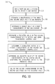
FIG. 10 is a flow chart of an embodiment of amethod 212 for controlling the blending of gases, utilizing the controller logic ofFIG. 8 . Instep 214, a first gas and a second gas may be mixed to create a gas mixture. In particular, the first and second gases may be theblast furnace gas 84 and thecoke oven gas 76 received from thesteel mill 68 to create afuel gas 66 mixture for use by thegas turbine 12. Instep 216, characteristics of the first and second gases and the resultant gas mixture may be determined. For instance, the LHVs of theblast furnace gas 84 and thecoke oven gas 76 may be measured by thegas chromatographs calorimeters system 90, as illustrated inFIG. 4 . Additionally, the LHV of thefuel gas 66 mixture may be measured at the inlet of the fuelgas control module 94 by thefuel gas calorimeter 166, as illustrated inFIG. 6 . In addition, flow rates of theblast furnace gas 84 andcoke oven gas 76 may be measured by theflowmeters system 90, as illustrated inFIG. 4 . - In
step 218, a target value for a first characteristic of the gas mixture may be determined. For instance, a target LHV for thefuel gas 66 mixture may be determined. Instep 220, a predicted value of a second characteristic of the second gas may be determined using feedforward control logic and the determined characteristics (from step 216) of the first and second gases and the gas mixture. In particular, a predicted value of the flow rate of thecoke oven gas 76 may be determined using feedforward control logic and the measured LHVs of theblast furnace gas 84, thecoke oven gas 76, and thefuel gas 66 mixture and the measured flow rates of theblast furnace gas 84 and thefuel gas 66 mixture, which are determined instep 216. Instep 222, a correction factor of the second characteristic of the second gas may be determined using feedback control logic by comparing the target value of the first characteristic of the gas mixture to a measured value of the first characteristic of the gas mixture. For instance, a correction factor of the flow rate of thecoke oven gas 76 may be determined based on a deviation observed between the target LHV of thefuel gas 66 mixture and the measured LHV of thefuel gas 66 mixture. - In
step 224, an adjusted value of the second characteristic of the second gas may be determined by comparing the correction factor (from step 220) to the predicted value (from step 222). In particular, an adjusted value of the flow rate of thecoke oven gas 76 may be determined based on a correction needed to meet the target LHV of thefuel gas 66 mixture. Instep 226, the second characteristic of the second gas may be adjusted based on the adjusted value determined instep 224. For instance, the flow rate of thecoke oven gas 76 may be adjusted by modulating theflow control valve 120 ofFIG. 4 based on the adjusted value. - Technical effects of the invention include providing a
controller 96 havingcontroller logic 188 configured to control the blending ofblast furnace gas 84 andcoke oven gas 76 from thesteel mill 68. By controlling the blending of these twosteel mill 68 by-product gases, thecontroller 96 may ensure that characteristics of thefuel gas 66 mixture delivered to thegas turbine 12 meet certain operating parameters for thegas turbine 12. For example, the heating value offuel gas 66 delivered to thegas turbine 12 may be maintained within acceptable minimum and maximum values. In doing so, the stability of the operation of thegas turbine 12 may be increased. In particular, combustion blowout and stalling of thegas turbine 12 may be minimized. In addition, by ensuring that blending of theblast furnace gas 84 and thecoke oven gas 76 is accomplished more effectively, the recovery of energy within these by-products gases of thesteel mill 68 may be enhanced. It should also be noted that while the embodiments disclosed herein are directed toward the blending ofblast furnace gas 84 andcoke oven gas 76, the control techniques described herein may be extended to the blending of other fuel and diluent sources. For example, in certain embodiments, the control techniques described herein may be used to control the blending of Corex with Nitrogen to obtain a target LHV for the Corex-Nitrogen blend. - This written description uses examples to disclose the invention, including the best mode, and also to enable any person skilled in the art to practice the invention, including making and using any devices or systems and performing any incorporated methods. The patentable scope of the invention is defined by the claims, and may include other examples that occur to those skilled in the art. Such other examples are intended to be within the scope of the claims if they have structural elements that do not differ from the literal language of the claims, or if they include equivalent structural elements with insubstantial differences from the literal languages of the claims.
- For completeness, various aspects of the invention are now set out in the following numbered clauses:
- 1. A system, comprising:
- a fuel system, comprising:
- a fuel blending system configured to blend a first fuel with a second fuel in a ratio to produce a third mixed fuel, wherein the first fuel has a first heating value, the second fuel has a second heating value, and the third mixed fuel has a third heating value, wherein the first heating value is lower than the second heating value; and
- a feedforward controller configured to adjust the ratio of the first and second fuels to correct the third heating value.
- a fuel system, comprising:
- 2. The system of
clause 1, wherein the feedforward controller is configured to adjust the ratio of the first and second fuels based at least in part on changes in moisture levels of the third mixed fuel, wherein the changes in moisture levels are introduced by cooling of the third mixed fuel. - 3. The system of
clause 1, wherein the first fuel comprises blast furnace gas and the second fuel comprises coke oven gas. - 4. The system of
clause 1, comprising a gas turbine engine coupled to the fuel system. - 5. The system of
clause 1, wherein the feedforward controller is configured to predict an adjusted flow rate of the second fuel to correct the third heating value based at least in part on measured flow rates and heating values of the first fuel, the second fuel, the third mixed fuel, or a combination thereof. - 6. The system of
clause 1, wherein the fuel system comprises:- a fuel cleanup system configured to remove particulates from the first fuel, the second fuel, and the third mixed fuel;
- a fuel compression system configured to increase pressure of the third mixed fuel; and
- a fuel control module configured to distribute the third mixed fuel to a turbine engine.
- 7. The system of
clause 1, comprising calorimeters that provide measured heating values of the first fuel, the second fuel, and the third mixed fuel to the feedforward controller, and flow meters that provide measured fuel flow rates to the feedforward controller. - 8. The system of clause 7, wherein the feedforward controller is configured to determine a predicted value of a fuel flow rate of the first fuel and/or the second fuel based at least in part on measured heating values and fuel flow rates.
- 9. The system of clause 8, wherein a feedback controller is configured to determine a correction factor of the fuel flow rate of the first fuel and/or the second fuel based at least in part on a comparison between a target heating value of the third mixed fuel to the measured heating value of the third mixed fuel.
- 10. A system, comprising:
- a turbine fuel blending controller, comprising:
- a feedforward control logic configured to predict a fuel flow rate of a first fuel and/or a second fuel being mixed to provide a third mixed fuel, wherein the first and second fuels have different heating values from one another, and
- a feedback control logic configured to correct the fuel flow rate based at least in part on a comparison between the target heating value and a measured heating value of the third mixed fuel.
- a turbine fuel blending controller, comprising:
- 11. The system of
clause 10, wherein the feedforward control logic is configured to predict the fuel flow rate of the second fuel based at least in part on the target heating value of the third mixed fuel, measured fuel flow rates of the first fuel and the third mixed fuel, and measured heating values of the first fuel, the second fuel, and the third mixed fuel. - 12. The system of clause 11, wherein the feedback control logic is configured to correct the fuel flow rate of the second fuel based at least in part on the predicted fuel flow rate of the second fuel, the comparison between the target heating value and the measured heating value of the third mixed fuel, the measured fuel flow rates of the first fuel and the third mixed fuel, and the measured heating values of the first fuel, the second fuel, and the third mixed fuel.
- 13. The system of
clause 10, wherein the feedback control logic is configured to correct the fuel flow rate based at least in part on changes in moisture levels of the third mixed fuel, wherein the changes in moisture levels are introduced by cooling of the third mixed fuel. - 14. The system of
clause 10, wherein the first fuel comprises blast furnace gas and the second fuel comprises coke oven gas. - 15. The system of
clause 10, comprising a gas turbine engine configured to receive the third mixed fuel. - 16. A method, comprising:
- blending a first fuel with a second fuel in a ratio to produce a third mixed fuel, wherein the first fuel has a first heating value, the second fuel has a second heating value, and the third mixed fuel has a third heating value, wherein the first heating value is different than the second heating value; and
- feedforward controlling the third heating value of the third mixed fuel via prediction and correction of a fuel flow rate of the first and/or second fuels to adjust the ratio of the first and second fuels based at least in part on a comparison between a measurement and a target for the third heating value.
- 17. The method of
claim 16, comprising:- receiving the first fuel from a blast furnace as blast furnace gas; and
- receiving the second fuel from a coke oven as coke oven gas.
- 18. The method of claim 17, comprising:
- measuring heating values of the blast furnace gas, the coke oven gas, and the third mixed fuel;
- measuring fuel flow rates of the blast furnace gas and the fuel gas mixture;
- determining a target heating value of the third mixed fuel;
- determining a predicted value of the fuel flow rate of the coke oven gas using feedforward control logic and the measured heating values of the blast furnace gas, the coke oven gas, and the third mixed fuel and the measured fuel flow rates of the blast furnace gas and the third mixed fuel;
- determining a correction factor of a fuel flow rate of the coke oven gas using feedback control logic by comparing the target heating value of the third mixed fuel to a measured heating value of the third mixed fuel;
- determining an adjusted value of the fuel flow rate of the coke oven gas by comparing the correction factor to the predicted value;
- adjusting the fuel flow rate of the coke oven gas by modulating a flow control valve through which the coke oven gas flows based on the adjusted value; and
- delivering the third mixed fuel, including the ratio of the coke oven gas and the blast furnace gas, to a turbine engine.
- 19. The method of
clause 16, wherein the feedforward controlling comprises determining a predicted value of the fuel flow rate of the second fuel based at least in part on measured heating values of the first fuel, the second fuel, and the third mixed fuel and fuel flow rates of the first fuel and the third mixed fuel. - 20. The method of clause 19, comprising determining a correction factor of the fuel flow rate of the second fuel based at least in part on a comparison between a target heating value of the third mixed fuel to the measured heating value of the third mixed fuel.
Claims (15)
- A system, comprising:a fuel system (64), comprising:a fuel blending system (90) configured to blend a first fuel (84) with a second fuel (76) in a ratio to produce a third mixed fuel (66), wherein the first fuel (84) has a first heating value, the second fuel (76) has a second heating value, and the third mixed fuel (66) has a third heating value, wherein the first heating value is lower than the second heating value; anda feedforward controller (96) configured to adjust the ratio of the first and second fuels (84, 76) to correct the third heating value.
- The system of claim 1, wherein the feedforward controller (96) is configured to adjust the ratio of the first and second fuels (84, 76) based at least in part on changes in moisture levels of the third mixed fuel (66), wherein the changes in moisture levels are introduced by cooling of the third mixed fuel (66).
- The system of claim 1 or 2, wherein the feedforward controller (96) is configured to predict an adjusted flow rate of the second fuel (76) to correct the third heating value based at least in part on measured flow rates and heating values of the first fuel (84), the second fuel (76), the third mixed fuel (66), or a combination thereof.
- The system of any of the preceding claims, comprising calorimeters (110, 112) that provide measured heating values of the first fuel (84), the second fuel (76), and the third mixed fuel (66) to the feedforward controller (96), and flow meters (122, 124) that provide measured fuel flow rates to the feedforward controller (96).
- The system of claim 4, wherein the feedforward controller (96) is configured to determine a predicted value of a fuel flow rate of the first fuel (84) and/or the second fuel (76) based at least in part on measured heating values and fuel flow rates.
- The system of claim 5, wherein a feedback controller (194) is configured to determine a correction factor of the fuel flow rate of the first fuel (84) and/or the second fuel (76) based at least in part on a comparison between a target heating value of the third mixed fuel (66) to the measured heating value of the third mixed fuel (66).
- A method, comprising:blending a first fuel (84) with a second fuel (76) in a ratio to produce a third mixed fuel (66), wherein the first fuel (84) has a first heating value, the second fuel (76) has a second heating value, and the third mixed fuel (66) has a third heating value, wherein the first heating value is different than the second heating value; andfeedforward controlling the third heating value of the third mixed fuel (66) via prediction and correction of a fuel flow rate of the first and/or second fuels (84, 76) to adjust the ratio of the first and second fuels (84, 76) based at least in part on a comparison between a measurement and a target for the third heating value.
- The method of claim 7, comprising:receiving the first fuel (84) from a blast furnace (80) as blast furnace gas (84); andreceiving the second fuel (76) from a coke oven (70) as coke oven gas (76).
- The method of claim 8, comprising:measuring heating values of the blast furnace gas (84), the coke oven gas (76), and the third mixed fuel (66);measuring fuel flow rates of the blast furnace gas (84) and the fuel gas mixture (66);determining a target heating value of the third mixed fuel (66);determining a predicted value of the fuel flow rate of the coke oven gas (76) using feedforward control logic (190) and the measured heating values of the blast furnace gas (84), the coke oven gas (76), and the third mixed fuel (66) and the measured fuel flow rates of the blast furnace gas (84) and the third mixed fuel (66);determining a correction factor of a fuel flow rate of the coke oven gas (76) using feedback control logic (194) by comparing the target heating value of the third mixed fuel (66) to a measured heating value of the third mixed fuel (66);determining an adjusted value of the fuel flow rate of the coke oven gas (76) by comparing the correction factor to the predicted value;adjusting the fuel flow rate of the coke oven gas (76) by modulating a flow control valve (120) through which the coke oven gas (76) flows based on the adjusted value; anddelivering the third mixed fuel (66), including the ratio of the coke oven gas (76) andthe blast furnace gas (84), to a turbine engine (12).
- The method of any of claims 7 to 9, wherein the feedforward controlling comprises determining a predicted value of the fuel flow rate of the second fuel (76) based at least in part on measured heating values of the first fuel (84), the second fuel (76), and the third mixed fuel (66) and fuel flow rates of the first fuel (84) and the third mixed fuel (66).
- The method of claim 10, comprising determining a correction factor of the fuel flow rate of the second fuel based at least in part on a comparison between a target heating value of the third mixed fuel to the measured heating value of the third mixed fuel.
- A system, comprising:a turbine fuel blending controller, comprising:a feedforward control logic configured to predict a fuel flow rate of a first fuel and/or a second fuel being mixed to provide a third mixed fuel, wherein the first and second fuels have different heating values from one another, anda feedback control logic configured to correct the fuel flow rate based at least in part on a comparison between the target heating value and a measured heating value of the third mixed fuel.
- The system of claim 12, wherein the feedforward control logic is configured to predict the fuel flow rate of the second fuel based at least in part on the target heating value of the third mixed fuel, measured fuel flow rates of the first fuel and the third mixed fuel, and measured heating values of the first fuel, the second fuel, and the third mixed fuel.
- The system of claim 13, wherein the feedback control logic is configured to correct the fuel flow rate of the second fuel based at least in part on the predicted fuel flow rate of the second fuel, the comparison between the target heating value and the measured heating value of the third mixed fuel, the measured fuel flow rates of the first fuel and the third mixed fuel, and the measured heating values of the first fuel, the second fuel, and the third mixed fuel.
- The system of any of claims 12 to 14, wherein the feedback control logic is configured to correct the fuel flow rate based at least in part on changes in moisture levels of the third mixed fuel, wherein the changes in moisture levels are introduced by cooling of the third mixed fuel.
Applications Claiming Priority (1)
| Application Number | Priority Date | Filing Date | Title |
|---|---|---|---|
| US12/401,512 US8381506B2 (en) | 2009-03-10 | 2009-03-10 | Low heating value fuel gas blending control |
Publications (3)
| Publication Number | Publication Date |
|---|---|
| EP2228524A2 true EP2228524A2 (en) | 2010-09-15 |
| EP2228524A3 EP2228524A3 (en) | 2014-07-02 |
| EP2228524B1 EP2228524B1 (en) | 2017-07-26 |
Family
ID=42124685
Family Applications (1)
| Application Number | Title | Priority Date | Filing Date |
|---|---|---|---|
| EP10155884.9A Active EP2228524B1 (en) | 2009-03-10 | 2010-03-09 | Low heating value fuel gas blending control |
Country Status (4)
| Country | Link |
|---|---|
| US (1) | US8381506B2 (en) |
| EP (1) | EP2228524B1 (en) |
| JP (1) | JP5719114B2 (en) |
| CN (1) | CN101832183B (en) |
Cited By (1)
| Publication number | Priority date | Publication date | Assignee | Title |
|---|---|---|---|---|
| WO2014149190A1 (en) * | 2013-03-15 | 2014-09-25 | General Electric Company | System and method for fuel blending and control in gas turbines |
Families Citing this family (29)
| Publication number | Priority date | Publication date | Assignee | Title |
|---|---|---|---|---|
| US9354618B2 (en) | 2009-05-08 | 2016-05-31 | Gas Turbine Efficiency Sweden Ab | Automated tuning of multiple fuel gas turbine combustion systems |
| US8437941B2 (en) | 2009-05-08 | 2013-05-07 | Gas Turbine Efficiency Sweden Ab | Automated tuning of gas turbine combustion systems |
| US9267443B2 (en) | 2009-05-08 | 2016-02-23 | Gas Turbine Efficiency Sweden Ab | Automated tuning of gas turbine combustion systems |
| US9671797B2 (en) | 2009-05-08 | 2017-06-06 | Gas Turbine Efficiency Sweden Ab | Optimization of gas turbine combustion systems low load performance on simple cycle and heat recovery steam generator applications |
| US20110036092A1 (en) * | 2009-08-12 | 2011-02-17 | General Electric Company | Methods and Systems for Dry Low NOx Combustion Systems |
| US20110266726A1 (en) * | 2010-05-03 | 2011-11-03 | General Electric Company | Gas turbine exhaust as hot blast for a blast furnace |
| JP5529676B2 (en) * | 2010-08-20 | 2014-06-25 | 三菱重工業株式会社 | Fuel supply system for gas turbine combustor and fuel supply method for gas turbine combustor |
| US20120180873A1 (en) * | 2011-01-14 | 2012-07-19 | General Electric Company | Method for replicating a pressure control valve with adjustable response characteristic |
| CN102979629A (en) * | 2011-09-07 | 2013-03-20 | 山西太钢不锈钢股份有限公司 | Operation method for matching high-heat-value gas with combustion engine rated at low heating value |
| JP5723455B2 (en) * | 2011-10-17 | 2015-05-27 | 川崎重工業株式会社 | Lean fuel intake gas turbine |
| JP5804888B2 (en) * | 2011-10-19 | 2015-11-04 | 三菱日立パワーシステムズ株式会社 | Control method for gas turbine power plant, gas turbine power plant, control method for carbon-containing fuel gasifier, and carbon-containing fuel gasifier |
| CH705965A1 (en) * | 2012-01-09 | 2013-07-15 | Alstom Technology Ltd | Method for operating a gas turbine. |
| US10107495B2 (en) | 2012-11-02 | 2018-10-23 | General Electric Company | Gas turbine combustor control system for stoichiometric combustion in the presence of a diluent |
| US9382850B2 (en) | 2013-03-21 | 2016-07-05 | General Electric Company | System and method for controlled fuel blending in gas turbines |
| JP6200731B2 (en) | 2013-09-05 | 2017-09-20 | 三菱日立パワーシステムズ株式会社 | Control method of gasification power generation system |
| CN104033310B (en) * | 2014-06-12 | 2015-10-21 | 浙江大学 | A Method for Adjusting the Ignition Advance Angle of a Coke Oven Gas Engine Based on Composition Detection |
| EP2993401B1 (en) * | 2014-09-02 | 2017-12-06 | Ansaldo Energia IP UK Limited | Method for controlling a gas turbine |
| CN104329672B (en) * | 2014-10-31 | 2017-01-25 | 中国神华能源股份有限公司 | Device and method for co-firing mine gas and natural gas |
| US20160208749A1 (en) * | 2015-01-20 | 2016-07-21 | Caterpillar Inc. | Multi-Fuel Engine And Method Of Operating The Same |
| WO2017188052A1 (en) * | 2016-04-26 | 2017-11-02 | 三菱日立パワーシステムズ株式会社 | Control device and control method for integrated gasification combined cycle power generation plant, and integrated gasification combined cycle power generation plant |
| JP6795390B2 (en) * | 2016-04-26 | 2020-12-02 | 三菱パワー株式会社 | Control device and control method of gasification combined cycle, and gasification combined cycle |
| WO2018009668A1 (en) * | 2016-07-08 | 2018-01-11 | Aggreko, Llc | Internal combustion engine fuel gas blending system |
| CN106867596A (en) * | 2017-03-29 | 2017-06-20 | 中冶东方控股有限公司 | A kind of calorific value adjusting apparatus of calcium carbide producer gas |
| KR102292145B1 (en) * | 2017-06-29 | 2021-08-20 | 제이에프이 스틸 가부시키가이샤 | Carbonization end time control method, carbonization end time control guidance display apparatus, coke oven operation method, and carbonization end time control apparatus |
| CN113175384A (en) * | 2021-05-28 | 2021-07-27 | 华电通用轻型燃机设备有限公司 | Coal chemical industry associated gas mixing treatment system suitable for gas turbine and working method |
| CN113236423A (en) * | 2021-06-16 | 2021-08-10 | 华电通用轻型燃机设备有限公司 | Gas turbine energy configuration system and method for generating power by using coal chemical associated gas |
| CN115686082B (en) * | 2022-10-11 | 2024-05-07 | 中国航发燃气轮机有限公司 | Non-stable heat value combustible gas intelligent gas distribution system for gas turbine |
| JP2024175961A (en) * | 2023-06-07 | 2024-12-19 | 三菱重工業株式会社 | Fuel supply system for gas turbine and method for controlling fuel supply system for gas turbine |
| US12378922B1 (en) | 2024-05-08 | 2025-08-05 | Pwrtek, Llc | Blending gaseous fuels for energy conversion systems |
Family Cites Families (13)
| Publication number | Priority date | Publication date | Assignee | Title |
|---|---|---|---|---|
| US4369803A (en) * | 1981-01-28 | 1983-01-25 | Phillips Petroleum Company | Control of fuel gas blending |
| US4677829A (en) * | 1986-02-07 | 1987-07-07 | Westinghouse Electric Corp. | Method for increasing the efficiency of gas turbine generator systems using low BTU gaseous fuels |
| US4761948A (en) * | 1987-04-09 | 1988-08-09 | Solar Turbines Incorporated | Wide range gaseous fuel combustion system for gas turbine engines |
| JPS63306239A (en) * | 1987-06-05 | 1988-12-14 | Hitachi Ltd | Coal gasification power generation system |
| JPH07102998A (en) * | 1993-10-05 | 1995-04-18 | Mitsubishi Heavy Ind Ltd | Fuel supply control method for gas turbine |
| DE19529110A1 (en) * | 1995-08-08 | 1997-02-13 | Abb Management Ag | Start-up procedure of a combination system |
| US6312154B1 (en) * | 2000-01-18 | 2001-11-06 | General Electric Company | Method for on-line measurement of fuel heat content of fuel in a combustion turbine system |
| JP4495971B2 (en) * | 2002-01-25 | 2010-07-07 | アルストム テクノロジー リミテッド | Method for operating a gas turbine group |
| JP3702266B2 (en) * | 2002-11-13 | 2005-10-05 | 三菱重工業株式会社 | Steam turbine output estimation device in dual fuel type single shaft combined plant |
| JP2006233920A (en) * | 2005-02-28 | 2006-09-07 | Mitsubishi Heavy Ind Ltd | System for controlling calorific value of fuel gas and gas-turbine system |
| JP4563242B2 (en) * | 2005-04-19 | 2010-10-13 | 三菱重工業株式会社 | Fuel gas calorie control method and apparatus |
| US7854110B2 (en) * | 2006-11-16 | 2010-12-21 | Siemens Energy, Inc. | Integrated fuel gas characterization system |
| US7950216B2 (en) * | 2007-01-30 | 2011-05-31 | Pratt & Whitney Canada Corp. | Gas turbine engine fuel control system |
-
2009
- 2009-03-10 US US12/401,512 patent/US8381506B2/en active Active
-
2010
- 2010-03-04 JP JP2010047246A patent/JP5719114B2/en active Active
- 2010-03-09 EP EP10155884.9A patent/EP2228524B1/en active Active
- 2010-03-10 CN CN201010143926.8A patent/CN101832183B/en active Active
Non-Patent Citations (1)
| Title |
|---|
| None |
Cited By (2)
| Publication number | Priority date | Publication date | Assignee | Title |
|---|---|---|---|---|
| WO2014149190A1 (en) * | 2013-03-15 | 2014-09-25 | General Electric Company | System and method for fuel blending and control in gas turbines |
| CN105190181B (en) * | 2013-03-15 | 2017-06-27 | 通用电气公司 | For the fuel mixing in gas turbine and the system and method for control |
Also Published As
| Publication number | Publication date |
|---|---|
| EP2228524B1 (en) | 2017-07-26 |
| US20100229524A1 (en) | 2010-09-16 |
| EP2228524A3 (en) | 2014-07-02 |
| US8381506B2 (en) | 2013-02-26 |
| CN101832183A (en) | 2010-09-15 |
| CN101832183B (en) | 2015-12-16 |
| JP2010209332A (en) | 2010-09-24 |
| JP5719114B2 (en) | 2015-05-13 |
Similar Documents
| Publication | Publication Date | Title |
|---|---|---|
| EP2228524B1 (en) | Low heating value fuel gas blending control | |
| US8408007B2 (en) | Integrated gasification combined cycle and operation control method thereof | |
| US8627668B2 (en) | System for fuel and diluent control | |
| EP2218889A2 (en) | Gas turbine plant with preheated combustion air and corresponding operating method | |
| US8117823B2 (en) | Method and system for increasing modified wobbe index control range | |
| CN103080560B (en) | Method for operating gas compressor, and gas turbine provided with gas compressor | |
| US7617687B2 (en) | Methods and systems of variable extraction for gas turbine control | |
| US20110266726A1 (en) | Gas turbine exhaust as hot blast for a blast furnace | |
| CN101014686B (en) | Gas reforming apparatus | |
| US10041407B2 (en) | System and method for air extraction from gas turbine engines | |
| CN100593672C (en) | Gas turbine facility, fuel gas supply facility, and method for suppressing increase in calorific value of fuel gas | |
| CN101023256B (en) | Gas turbine equipment, low-calorie gas supply equipment, and method for suppressing heat rise of the gas | |
| US8545580B2 (en) | Chemically-modified mixed fuels, methods of production and uses thereof | |
| WO2006035522A1 (en) | Gas turbine apparatus, low calorie content gas feeding apparatus, and method of suppressing rise of calorie content of the gas | |
| JP5000223B2 (en) | Compressor control device and coal gasification power generation system | |
| JP2007170245A (en) | Gas turbine facility, low calory gas feeding facility, and method of suppressing rise of calory of gas |
Legal Events
| Date | Code | Title | Description |
|---|---|---|---|
| PUAI | Public reference made under article 153(3) epc to a published international application that has entered the european phase |
Free format text: ORIGINAL CODE: 0009012 |
|
| AK | Designated contracting states |
Kind code of ref document: A2 Designated state(s): AT BE BG CH CY CZ DE DK EE ES FI FR GB GR HR HU IE IS IT LI LT LU LV MC MK MT NL NO PL PT RO SE SI SK SM TR |
|
| AX | Request for extension of the european patent |
Extension state: AL BA ME RS |
|
| PUAL | Search report despatched |
Free format text: ORIGINAL CODE: 0009013 |
|
| AK | Designated contracting states |
Kind code of ref document: A3 Designated state(s): AT BE BG CH CY CZ DE DK EE ES FI FR GB GR HR HU IE IS IT LI LT LU LV MC MK MT NL NO PL PT RO SE SI SK SM TR |
|
| AX | Request for extension of the european patent |
Extension state: AL BA ME RS |
|
| RIC1 | Information provided on ipc code assigned before grant |
Ipc: F02C 9/40 20060101ALI20140523BHEP Ipc: F02C 9/26 20060101ALI20140523BHEP Ipc: C10K 3/06 20060101ALI20140523BHEP Ipc: F02C 3/28 20060101AFI20140523BHEP |
|
| 17P | Request for examination filed |
Effective date: 20150105 |
|
| RBV | Designated contracting states (corrected) |
Designated state(s): AT BE BG CH CY CZ DE DK EE ES FI FR GB GR HR HU IE IS IT LI LT LU LV MC MK MT NL NO PL PT RO SE SI SK SM TR |
|
| RIC1 | Information provided on ipc code assigned before grant |
Ipc: C10K 3/06 20060101ALI20170223BHEP Ipc: F02C 3/28 20060101AFI20170223BHEP Ipc: F02C 9/40 20060101ALI20170223BHEP Ipc: F02C 9/26 20060101ALI20170223BHEP |
|
| GRAP | Despatch of communication of intention to grant a patent |
Free format text: ORIGINAL CODE: EPIDOSNIGR1 |
|
| INTG | Intention to grant announced |
Effective date: 20170405 |
|
| GRAS | Grant fee paid |
Free format text: ORIGINAL CODE: EPIDOSNIGR3 |
|
| GRAA | (expected) grant |
Free format text: ORIGINAL CODE: 0009210 |
|
| AK | Designated contracting states |
Kind code of ref document: B1 Designated state(s): AT BE BG CH CY CZ DE DK EE ES FI FR GB GR HR HU IE IS IT LI LT LU LV MC MK MT NL NO PL PT RO SE SI SK SM TR |
|
| REG | Reference to a national code |
Ref country code: GB Ref legal event code: FG4D |
|
| REG | Reference to a national code |
Ref country code: CH Ref legal event code: EP |
|
| REG | Reference to a national code |
Ref country code: AT Ref legal event code: REF Ref document number: 912608 Country of ref document: AT Kind code of ref document: T Effective date: 20170815 |
|
| REG | Reference to a national code |
Ref country code: IE Ref legal event code: FG4D |
|
| REG | Reference to a national code |
Ref country code: DE Ref legal event code: R096 Ref document number: 602010043834 Country of ref document: DE |
|
| REG | Reference to a national code |
Ref country code: NL Ref legal event code: MP Effective date: 20170726 |
|
| REG | Reference to a national code |
Ref country code: LT Ref legal event code: MG4D |
|
| REG | Reference to a national code |
Ref country code: AT Ref legal event code: MK05 Ref document number: 912608 Country of ref document: AT Kind code of ref document: T Effective date: 20170726 |
|
| PG25 | Lapsed in a contracting state [announced via postgrant information from national office to epo] |
Ref country code: AT Free format text: LAPSE BECAUSE OF FAILURE TO SUBMIT A TRANSLATION OF THE DESCRIPTION OR TO PAY THE FEE WITHIN THE PRESCRIBED TIME-LIMIT Effective date: 20170726 Ref country code: NL Free format text: LAPSE BECAUSE OF FAILURE TO SUBMIT A TRANSLATION OF THE DESCRIPTION OR TO PAY THE FEE WITHIN THE PRESCRIBED TIME-LIMIT Effective date: 20170726 Ref country code: HR Free format text: LAPSE BECAUSE OF FAILURE TO SUBMIT A TRANSLATION OF THE DESCRIPTION OR TO PAY THE FEE WITHIN THE PRESCRIBED TIME-LIMIT Effective date: 20170726 Ref country code: FI Free format text: LAPSE BECAUSE OF FAILURE TO SUBMIT A TRANSLATION OF THE DESCRIPTION OR TO PAY THE FEE WITHIN THE PRESCRIBED TIME-LIMIT Effective date: 20170726 Ref country code: NO Free format text: LAPSE BECAUSE OF FAILURE TO SUBMIT A TRANSLATION OF THE DESCRIPTION OR TO PAY THE FEE WITHIN THE PRESCRIBED TIME-LIMIT Effective date: 20171026 Ref country code: LT Free format text: LAPSE BECAUSE OF FAILURE TO SUBMIT A TRANSLATION OF THE DESCRIPTION OR TO PAY THE FEE WITHIN THE PRESCRIBED TIME-LIMIT Effective date: 20170726 Ref country code: SE Free format text: LAPSE BECAUSE OF FAILURE TO SUBMIT A TRANSLATION OF THE DESCRIPTION OR TO PAY THE FEE WITHIN THE PRESCRIBED TIME-LIMIT Effective date: 20170726 |
|
| PG25 | Lapsed in a contracting state [announced via postgrant information from national office to epo] |
Ref country code: GR Free format text: LAPSE BECAUSE OF FAILURE TO SUBMIT A TRANSLATION OF THE DESCRIPTION OR TO PAY THE FEE WITHIN THE PRESCRIBED TIME-LIMIT Effective date: 20171027 Ref country code: LV Free format text: LAPSE BECAUSE OF FAILURE TO SUBMIT A TRANSLATION OF THE DESCRIPTION OR TO PAY THE FEE WITHIN THE PRESCRIBED TIME-LIMIT Effective date: 20170726 Ref country code: ES Free format text: LAPSE BECAUSE OF FAILURE TO SUBMIT A TRANSLATION OF THE DESCRIPTION OR TO PAY THE FEE WITHIN THE PRESCRIBED TIME-LIMIT Effective date: 20170726 Ref country code: PL Free format text: LAPSE BECAUSE OF FAILURE TO SUBMIT A TRANSLATION OF THE DESCRIPTION OR TO PAY THE FEE WITHIN THE PRESCRIBED TIME-LIMIT Effective date: 20170726 Ref country code: IS Free format text: LAPSE BECAUSE OF FAILURE TO SUBMIT A TRANSLATION OF THE DESCRIPTION OR TO PAY THE FEE WITHIN THE PRESCRIBED TIME-LIMIT Effective date: 20171126 Ref country code: BG Free format text: LAPSE BECAUSE OF FAILURE TO SUBMIT A TRANSLATION OF THE DESCRIPTION OR TO PAY THE FEE WITHIN THE PRESCRIBED TIME-LIMIT Effective date: 20171026 |
|
| PG25 | Lapsed in a contracting state [announced via postgrant information from national office to epo] |
Ref country code: DK Free format text: LAPSE BECAUSE OF FAILURE TO SUBMIT A TRANSLATION OF THE DESCRIPTION OR TO PAY THE FEE WITHIN THE PRESCRIBED TIME-LIMIT Effective date: 20170726 Ref country code: RO Free format text: LAPSE BECAUSE OF FAILURE TO SUBMIT A TRANSLATION OF THE DESCRIPTION OR TO PAY THE FEE WITHIN THE PRESCRIBED TIME-LIMIT Effective date: 20170726 Ref country code: CZ Free format text: LAPSE BECAUSE OF FAILURE TO SUBMIT A TRANSLATION OF THE DESCRIPTION OR TO PAY THE FEE WITHIN THE PRESCRIBED TIME-LIMIT Effective date: 20170726 |
|
| REG | Reference to a national code |
Ref country code: DE Ref legal event code: R097 Ref document number: 602010043834 Country of ref document: DE |
|
| PG25 | Lapsed in a contracting state [announced via postgrant information from national office to epo] |
Ref country code: EE Free format text: LAPSE BECAUSE OF FAILURE TO SUBMIT A TRANSLATION OF THE DESCRIPTION OR TO PAY THE FEE WITHIN THE PRESCRIBED TIME-LIMIT Effective date: 20170726 Ref country code: SK Free format text: LAPSE BECAUSE OF FAILURE TO SUBMIT A TRANSLATION OF THE DESCRIPTION OR TO PAY THE FEE WITHIN THE PRESCRIBED TIME-LIMIT Effective date: 20170726 Ref country code: SM Free format text: LAPSE BECAUSE OF FAILURE TO SUBMIT A TRANSLATION OF THE DESCRIPTION OR TO PAY THE FEE WITHIN THE PRESCRIBED TIME-LIMIT Effective date: 20170726 |
|
| PLBE | No opposition filed within time limit |
Free format text: ORIGINAL CODE: 0009261 |
|
| STAA | Information on the status of an ep patent application or granted ep patent |
Free format text: STATUS: NO OPPOSITION FILED WITHIN TIME LIMIT |
|
| 26N | No opposition filed |
Effective date: 20180430 |
|
| PG25 | Lapsed in a contracting state [announced via postgrant information from national office to epo] |
Ref country code: SI Free format text: LAPSE BECAUSE OF FAILURE TO SUBMIT A TRANSLATION OF THE DESCRIPTION OR TO PAY THE FEE WITHIN THE PRESCRIBED TIME-LIMIT Effective date: 20170726 |
|
| REG | Reference to a national code |
Ref country code: CH Ref legal event code: PL |
|
| GBPC | Gb: european patent ceased through non-payment of renewal fee |
Effective date: 20180309 |
|
| PG25 | Lapsed in a contracting state [announced via postgrant information from national office to epo] |
Ref country code: MC Free format text: LAPSE BECAUSE OF FAILURE TO SUBMIT A TRANSLATION OF THE DESCRIPTION OR TO PAY THE FEE WITHIN THE PRESCRIBED TIME-LIMIT Effective date: 20170726 |
|
| REG | Reference to a national code |
Ref country code: BE Ref legal event code: MM Effective date: 20180331 |
|
| REG | Reference to a national code |
Ref country code: IE Ref legal event code: MM4A |
|
| PG25 | Lapsed in a contracting state [announced via postgrant information from national office to epo] |
Ref country code: LU Free format text: LAPSE BECAUSE OF NON-PAYMENT OF DUE FEES Effective date: 20180309 |
|
| PG25 | Lapsed in a contracting state [announced via postgrant information from national office to epo] |
Ref country code: IE Free format text: LAPSE BECAUSE OF NON-PAYMENT OF DUE FEES Effective date: 20180309 |
|
| PG25 | Lapsed in a contracting state [announced via postgrant information from national office to epo] |
Ref country code: LI Free format text: LAPSE BECAUSE OF NON-PAYMENT OF DUE FEES Effective date: 20180331 Ref country code: CH Free format text: LAPSE BECAUSE OF NON-PAYMENT OF DUE FEES Effective date: 20180331 Ref country code: GB Free format text: LAPSE BECAUSE OF NON-PAYMENT OF DUE FEES Effective date: 20180309 Ref country code: BE Free format text: LAPSE BECAUSE OF NON-PAYMENT OF DUE FEES Effective date: 20180331 |
|
| PG25 | Lapsed in a contracting state [announced via postgrant information from national office to epo] |
Ref country code: FR Free format text: LAPSE BECAUSE OF NON-PAYMENT OF DUE FEES Effective date: 20180331 |
|
| PG25 | Lapsed in a contracting state [announced via postgrant information from national office to epo] |
Ref country code: MT Free format text: LAPSE BECAUSE OF NON-PAYMENT OF DUE FEES Effective date: 20180309 |
|
| PG25 | Lapsed in a contracting state [announced via postgrant information from national office to epo] |
Ref country code: TR Free format text: LAPSE BECAUSE OF FAILURE TO SUBMIT A TRANSLATION OF THE DESCRIPTION OR TO PAY THE FEE WITHIN THE PRESCRIBED TIME-LIMIT Effective date: 20170726 |
|
| PG25 | Lapsed in a contracting state [announced via postgrant information from national office to epo] |
Ref country code: HU Free format text: LAPSE BECAUSE OF FAILURE TO SUBMIT A TRANSLATION OF THE DESCRIPTION OR TO PAY THE FEE WITHIN THE PRESCRIBED TIME-LIMIT; INVALID AB INITIO Effective date: 20100309 Ref country code: PT Free format text: LAPSE BECAUSE OF FAILURE TO SUBMIT A TRANSLATION OF THE DESCRIPTION OR TO PAY THE FEE WITHIN THE PRESCRIBED TIME-LIMIT Effective date: 20170726 |
|
| PG25 | Lapsed in a contracting state [announced via postgrant information from national office to epo] |
Ref country code: CY Free format text: LAPSE BECAUSE OF FAILURE TO SUBMIT A TRANSLATION OF THE DESCRIPTION OR TO PAY THE FEE WITHIN THE PRESCRIBED TIME-LIMIT Effective date: 20170726 Ref country code: MK Free format text: LAPSE BECAUSE OF NON-PAYMENT OF DUE FEES Effective date: 20170726 |
|
| P01 | Opt-out of the competence of the unified patent court (upc) registered |
Effective date: 20230522 |
|
| REG | Reference to a national code |
Ref country code: DE Ref legal event code: R081 Ref document number: 602010043834 Country of ref document: DE Owner name: GENERAL ELECTRIC TECHNOLOGY GMBH, CH Free format text: FORMER OWNER: GENERAL ELECTRIC COMPANY, SCHENECTADY, NY, US |
|
| PGFP | Annual fee paid to national office [announced via postgrant information from national office to epo] |
Ref country code: DE Payment date: 20260219 Year of fee payment: 17 |
|
| PGFP | Annual fee paid to national office [announced via postgrant information from national office to epo] |
Ref country code: IT Payment date: 20260219 Year of fee payment: 17 |