EP2228517B1 - A cooled airfoil and an impingement baffle insert therefor - Google Patents
A cooled airfoil and an impingement baffle insert therefor Download PDFInfo
- Publication number
- EP2228517B1 EP2228517B1 EP10250478.4A EP10250478A EP2228517B1 EP 2228517 B1 EP2228517 B1 EP 2228517B1 EP 10250478 A EP10250478 A EP 10250478A EP 2228517 B1 EP2228517 B1 EP 2228517B1
- Authority
- EP
- European Patent Office
- Prior art keywords
- airfoil
- cooling
- baffle
- segment
- baffle insert
- Prior art date
- Legal status (The legal status is an assumption and is not a legal conclusion. Google has not performed a legal analysis and makes no representation as to the accuracy of the status listed.)
- Active
Links
- 238000001816 cooling Methods 0.000 claims description 146
- 239000002184 metal Substances 0.000 claims description 5
- 238000002156 mixing Methods 0.000 claims description 2
- 239000007789 gas Substances 0.000 description 40
- 239000000567 combustion gas Substances 0.000 description 3
- 238000004519 manufacturing process Methods 0.000 description 3
- 238000002844 melting Methods 0.000 description 3
- 230000008018 melting Effects 0.000 description 3
- 238000005192 partition Methods 0.000 description 3
- 238000007493 shaping process Methods 0.000 description 3
- 239000000956 alloy Substances 0.000 description 2
- 229910045601 alloy Inorganic materials 0.000 description 2
- 238000005266 casting Methods 0.000 description 2
- 230000003993 interaction Effects 0.000 description 2
- 239000000463 material Substances 0.000 description 2
- 230000015572 biosynthetic process Effects 0.000 description 1
- 230000008859 change Effects 0.000 description 1
- 238000002485 combustion reaction Methods 0.000 description 1
- 238000007796 conventional method Methods 0.000 description 1
- 238000002788 crimping Methods 0.000 description 1
- 230000000694 effects Effects 0.000 description 1
- 230000005611 electricity Effects 0.000 description 1
- 239000000203 mixture Substances 0.000 description 1
- 238000012986 modification Methods 0.000 description 1
- 230000004048 modification Effects 0.000 description 1
- 238000011144 upstream manufacturing Methods 0.000 description 1
- 238000003466 welding Methods 0.000 description 1
Images


Classifications
-
- F—MECHANICAL ENGINEERING; LIGHTING; HEATING; WEAPONS; BLASTING
- F01—MACHINES OR ENGINES IN GENERAL; ENGINE PLANTS IN GENERAL; STEAM ENGINES
- F01D—NON-POSITIVE DISPLACEMENT MACHINES OR ENGINES, e.g. STEAM TURBINES
- F01D5/00—Blades; Blade-carrying members; Heating, heat-insulating, cooling or antivibration means on the blades or the members
- F01D5/12—Blades
- F01D5/14—Form or construction
- F01D5/18—Hollow blades, i.e. blades with cooling or heating channels or cavities; Heating, heat-insulating or cooling means on blades
- F01D5/187—Convection cooling
- F01D5/188—Convection cooling with an insert in the blade cavity to guide the cooling fluid, e.g. forming a separation wall
- F01D5/189—Convection cooling with an insert in the blade cavity to guide the cooling fluid, e.g. forming a separation wall the insert having a tubular cross-section, e.g. airfoil shape
-
- F—MECHANICAL ENGINEERING; LIGHTING; HEATING; WEAPONS; BLASTING
- F05—INDEXING SCHEMES RELATING TO ENGINES OR PUMPS IN VARIOUS SUBCLASSES OF CLASSES F01-F04
- F05D—INDEXING SCHEME FOR ASPECTS RELATING TO NON-POSITIVE-DISPLACEMENT MACHINES OR ENGINES, GAS-TURBINES OR JET-PROPULSION PLANTS
- F05D2240/00—Components
- F05D2240/10—Stators
- F05D2240/12—Fluid guiding means, e.g. vanes
- F05D2240/121—Fluid guiding means, e.g. vanes related to the leading edge of a stator vane
-
- F—MECHANICAL ENGINEERING; LIGHTING; HEATING; WEAPONS; BLASTING
- F05—INDEXING SCHEMES RELATING TO ENGINES OR PUMPS IN VARIOUS SUBCLASSES OF CLASSES F01-F04
- F05D—INDEXING SCHEME FOR ASPECTS RELATING TO NON-POSITIVE-DISPLACEMENT MACHINES OR ENGINES, GAS-TURBINES OR JET-PROPULSION PLANTS
- F05D2240/00—Components
- F05D2240/20—Rotors
- F05D2240/30—Characteristics of rotor blades, i.e. of any element transforming dynamic fluid energy to or from rotational energy and being attached to a rotor
- F05D2240/303—Characteristics of rotor blades, i.e. of any element transforming dynamic fluid energy to or from rotational energy and being attached to a rotor related to the leading edge of a rotor blade
-
- F—MECHANICAL ENGINEERING; LIGHTING; HEATING; WEAPONS; BLASTING
- F05—INDEXING SCHEMES RELATING TO ENGINES OR PUMPS IN VARIOUS SUBCLASSES OF CLASSES F01-F04
- F05D—INDEXING SCHEME FOR ASPECTS RELATING TO NON-POSITIVE-DISPLACEMENT MACHINES OR ENGINES, GAS-TURBINES OR JET-PROPULSION PLANTS
- F05D2260/00—Function
- F05D2260/20—Heat transfer, e.g. cooling
- F05D2260/201—Heat transfer, e.g. cooling by impingement of a fluid
Definitions
- the present invention is related to cooling of airfoils for gas turbine engines and, more particularly, to baffle inserts for impingement cooling of airfoil vanes.
- Gas turbine engines operate by passing a volume of high energy gases through a series of compressors and turbines in order to produce rotational shaft power.
- the shaft power is used to turn a turbine for driving a compressor to provide air to a combustion process to generate the high energy gases.
- the shaft power is used to power a secondary turbine to, for example, drive a generator for producing electricity, or to produce high momentum gases for producing thrust.
- Each compressor and turbine comprises a plurality of stages of vanes and blades, each having an airfoil, with the rotating blades pushing air past the stationary vanes.
- stators redirect the trajectory of the air coming off the rotors for flow into the next stage.
- stators convert kinetic energy of moving air into pressure, while, in the turbine, stators accelerate pressurized air to extract kinetic energy.
- the vanes and blades are subjected to extremely high temperatures, often times exceeding the melting point of the alloys used to make the airfoils.
- the leading edge of an airfoil which impinges most directly with the heated gases, is heated to the highest temperature along the airfoil.
- the airfoils are maintained at temperatures below their melting point by, among other things, cooling the airfoils with a supply of relatively cooler air that is typically siphoned from a compressor.
- the cooling air is directed into the blade or vane to provide cooling of the airfoil through various modes including impingement cooling.
- the cooling air is passed into an interior of the airfoil to remove heat from the alloy.
- the cooling air is subsequently discharged through cooling holes in the airfoil to pass over the outer surface of the airfoil to prevent the hot gases from contacting the vane or blade.
- the cooling air is typically directed into a baffle disposed within a vane interior and having a plurality cooling holes. Cooling air from the cooling holes impinges on an interior surface of the vane before exiting the vane at a trailing edge discharge slot.
- baffle design Due to the extremely thin nature of the baffle, it is difficult to control the cooling air as it leaves the baffle.
- Various baffle designs have been developed to better distribute cooling air along the interior surfaces of the vane. Many previous baffle designs require extensive fabricating, shaping and assembly steps, which increase manufacturing time and expense. There is, therefore, a need for a simpler baffle design that is easy to produce and cost effective.
- the present invention provides a baffle insert for an internally cooled airfoil, the baffle insert comprising: a liner having a continuous perimeter formed to shape a hollow body having a first end and a second end; a divoted segment of the hollow body positioned between the first end and the second end; and a plurality of cooling holes positioned on the divoted segment to aim cooling air exiting the baffle insert, wherein the divoted segment comprises an elongate, longitudinal depression in the hollow body extending between the first end and the second end, wherein the depression comprises: a first curved segment having a first column of cooling holes; a second curved segment having a second column of cooling holes; and an elbow segment connecting the first curved segment with the second curved segment and having a third column of cooling holes, wherein the first and second curved segments are curved to direct air through the first and second columns of cooling holes at angles oblique to an interior surface of the airfoil, and characterised in that: the elbow segment is curved to direct air through the third column of cooling holes
- FIG. 1 shows a perspective view of stationary turbine vane 10 having airfoil 12, outer diameter vane shroud 14, inner diameter vane shroud 16 and baffle 18.
- Airfoil 12 includes leading edge 20, pressure side 22, suction side 24 and trailing edge 26.
- Baffle 18 includes divot 28.
- Turbine vane 10 is a stationary vane that receives high energy gas G in a turbine section of a gas turbine engine. In other embodiments, vane 10 is used in a compressor section of a gas turbine engine. The outer diameter end of airfoil 12 mates with shroud 14 and the inner diameter end of airfoil 12 mates with shroud 16. Shrouds 14 and 16 are connected to adjacent shrouds within the gas turbine engine to form structures between which airfoil 12 is supported. Outer diameter shrouds 14 are connected using, for example, threaded fasteners and suspended from an outer diameter engine case. Inner diameter shrouds 16 are similarly connected and supported by inner diameter support struts. Turbine vanes 10 operate to increase the efficiency of the gas turbine engine in which they are installed.
- Vane shroud 14 and vane shroud 16 increase the efficiency of the gas turbine engine by forming outer and inner boundaries for the flow of gas G through the gas turbine engine. Vane shrouds 14 and 16 prevent escape of gas G from the gas turbine engine such that more air is available for performing work.
- the shape of vane 10 also increases the efficiency of the gas turbine engine. Vane 10 generally functions to redirect the trajectory of gas G coming from a combustor section or a blade of an upstream turbine stage to a blade of a downstream turbine stage. Pressure side 22 and suction side 24 redirect the flow of gas G received at leading edge 20 such that, after passing by trailing edge 26, the incidence of gas G on the subsequent rotor blade stage is optimized. As such, more work can be extracted from the interaction of gas G with downstream blades.
- vane 10 comprises a high pressure turbine vane that is positioned downstream of a combustor section of a gas turbine engine to receive hot combustion gas.
- Airfoil 12 is, therefore, subjected to a concentrated, steady stream of combustion gas G during operation of the gas turbine engine.
- the extremely elevated temperatures of combustion gas G often exceed the melting point of the material forming vane 10.
- Airfoil 12 is therefore cooled using cooling air provided by, for example, relatively cooler air bled from a compressor section within the gas turbine engine.
- the cooling air is directed into baffle 18 where small cooling holes distribute the cooling air to perform impingement cooling on the interior of airfoil 12. Divot 28 focuses a portion of the cooling air onto hotspots of airfoil 12.
- FIG. 2 is a partially broken away perspective view of stationary turbine vane 10 of FIG. 1 showing the position of pressure side divot 28 and leading edge divot 30 of baffle 18 with respect to airfoil 12.
- Pressure side divot 28 and leading edge divot 30 include cooling holes 32 and cooling holes 34, respectively.
- Airfoil 12 comprises a thin-walled hollow structure that forms internal cavity 36 for receiving baffle 18 between shrouds 14 and 16.
- Baffle 18 comprises a hollow, sheet metal structure that forms cooling air supply duct 38.
- outer diameter shroud 14 includes an opening to receive baffle 18, while inner diameter shroud 16 is closed to support baffle 18.
- Baffle 18 is typically joined, such as by welding, to either outer diameter shroud 14 or inner diameter shroud 16, while remaining free at the opposite end.
- the ends of baffle 18 are open to receive cooling air A for cooling airfoil 12 from temperatures produced by hot gas G.
- one end of baffle 18 is closed or semi-closed to assist in forcing cooling air A out cooling holes 32 and 34.
- the closed or semi-closed end of baffle 18 is the end not connected to shrouds 14 and 16.
- Cooling air A enters supply duct 38 of baffle 18, passes through cooling holes 32 and 34 and enters internal cavity 36 to perform impingement cooling on the interior of airfoil 12.
- Cooling holes 32 and 34 comprise columns of cooling holes that extend across divots 28 and 30, respectively.
- Divots 28 and 30 comprise elongate, longitudinal depressions within baffle 18 that extend from the outer diameter end to the inner diameter end of baffle 18. As such, cooling holes 32 and 34 are directed across the entire span of airfoil 12. In other embodiments, however, divots 28 and 30 need not extend the entire length of baffle 18. Divots 28 and 30 are contoured so as to form surfaces into which cooling holes 32 and 34 are disposed to face airfoil 12 at different angles.
- cooling holes 32 comprise a series of three columns disposed along surfaces of divot 28.
- cooling holes 34 comprise a series of three columns disposed along surfaces of divot 30.
- only one or two columns of cooling holes may be used.
- a single column could extend along the center of divot 28, or a pair of columns could extend along the sides of divot 28.
- the spacing between cooling holes in each column can be varied to direct more cooling air to hotter portions of airfoil 12.
- the surfaces of divots 28 and 30 are shaped to deliver a concentrated volume of cooling air A to different longitudinal sections of airfoil 12. As such, divots 28 and 30 operate independently to cool a hotspot along airfoil 12 and need not be used together.
- Various divots can be positioned on any surface around the perimeter of baffle 18, including suction side 24.
- Hot gas G flows across vane 10, impinges leading edge 20 and flows across suction side 22 and pressure side 24 of airfoil 12.
- the flow dynamics of gas G produced by the geometry of airfoil 12 may result in a particular portion of airfoil 12 developing a hotspot where the temperature rises to levels above where the temperature is at other places along airfoil 12.
- the specific design of airfoil 12 may lead to hotspots based on the manner with which pressure side 22 engages gas G to perform work.
- leading edge 20 of airfoil 12 is particularly susceptible to hotspots due to interaction with the hottest portions of the flow of gas G.
- Direct impingement of gas G on leading edge 20 also inhibits the formation of turbulent flow across airfoil 12 that provides a buffer against gas G. As such, it is desirable to deliver additional cooling air A to hotspots on airfoil 12.
- Divot 28 is positioned on the pressure side of baffle 18 to deliver cooling air A to a hotspot along a longitudinal section of airfoil 12 at a specific chord-wise position on pressure side 22.
- Divot 30 is positioned on the leading edge of baffle 18 to deliver cooling air A to a hotspot along a longitudinal section of airfoil 12 at leading edge 20.
- the contours of divot 28 and divot 30 aim the columns of cooling holes 32 and 34, respectively, to the hotspots to reduce the temperature of airfoil 12.
- FIG. 3 is a cross-sectional view of stationary vane 10 of FIG. 1 taken at section 3 - 3 showing cooling circuit 40 between airfoil 12 and baffle 18.
- Airfoil 12 includes leading edge 20, pressure side 22, suction side 24, trailing edge 26, pedestals 42A - 42D and discharge slot 44.
- Baffle 18 includes pressure side divot 28, leading edge divot 30, pressure side cooling holes 32 and leading edge cooling holes 34. Baffle 18 is inserted into internal cavity 36 and is maintained at a minimum distance from airfoil 12 by standoffs (not shown).
- Hot gas G such as from a combustor of a gas turbine engine, impinges leading edge 20 of airfoil 12.
- Pressurized cooling air A such as relatively cooler air from a compressor of the gas turbine engine, is directed into supply duct 38 of baffle 18.
- Airfoil 12 is fabricated, typically by casting, as a thin-walled structure in the shape of an airfoil.
- the leading edge portions of pressure side 22 and suction side 24 are displaced from each other to form internal cavity 36.
- internal cavity 36 comprises a single space, but in other embodiments cavity 36 may be divided into segments using integral partitions.
- Internal cavity 36 continually narrows as internal cavity 36 progresses from leading edge 20 toward trailing edge 26. Pressure side 22 and suction side 24 do not touch at trailing edge 26 such that discharge slot 44 is formed.
- the trailing edge portions of pressure side 22 and suction side 24 are supported with pedestals 42A - 42D.
- Pedestals 42A - 42D typically comprise small-diameter cylindrical stanchions that span the distance between pressure side 22 and suction side 24. Pedestals 42A - 42D are staggered so as to form an anfractuous flow path between cavity 36 and discharge slot 44.
- Baffle 18 is formed into the general shape of an airfoil so as to match the shape of internal cavity 36.
- baffle 18 includes a leading edge profile that tracks with leading edge 20.
- a baffle can be provided to each segment of cavity 36.
- the profile of baffle 18 may have other configurations, such as having a flat surface to track with a partition.
- a plurality of divots can be positioned along any surface of a baffle to cool a plurality of unique hotspots.
- the perimeter of baffle 18 is continuous such that a simple hoop-shaped structure is formed.
- the walls of baffle 18 are shaped such that duct 38 comprises a single chamber.
- baffle 18 is minimally shaped to facilitate easy manufacture.
- Baffle 18 is typically formed from thin sheet metal. First, a pattern is cut from a piece of flat sheet metal. Next, the pattern is bent to form a rough-shaped hollow body. The ends of the hollow body are welded such that the baffle has a continuous perimeter. The shape of the hollow body is then finished using a series of die-shaping steps which give the hollow body the general shape of an airfoil. Other features, such as standoffs and divots, can be easily formed into the sheet metal using the die-shaping steps. The divots are positioned away from the welded seam such that the divots are seamless. In one embodiment, the welded seam is positioned away from the leading edge of baffle 18 such that leading edge divot 30 of baffle 18 is seamless.
- baffle 18 The top and bottom of the hollow, airfoil-shaped structure can then be trimmed to give baffle 18 the desired height for use with a specific vane. If desired, an end of baffle 18 can be closed or semi-closed by crimping and then welded shut if fully closed. Plates can then be welded to each end to facilitate connection with shrouds 14 and 16. Finally, cooling holes are produced in baffle 18 using any conventional method.
- Baffle 18 is disposed within airfoil 12 such that cooling circuit 40 is formed within cavity 36.
- Standoffs which may be integrally formed with baffle 18 or airfoil 12, comprise small pads that extend across circuit 40 to inhibit movement of baffle 18 within cavity 36.
- Cavity 36 within airfoil 12 is open to duct 38 within baffle 18 through cooling holes 32 and 34. As such, a pressure differential is produced between cavity 36 and duct 38 when cooling air A is directed into baffle 18. Cooling air A is thus pushed through cooling holes 32 and 34 into cavity 36. Cooling holes 34 shape cooling air A into a plurality of small air jets J. Similarly, jets of cooling air A enter cavity 36 through cooling holes 32, but illustration of such air jets is omitted for clarity.
- Baffle 18 typically also includes other cooling holes (not shown) that are distributed over the entirety of baffle 18 for cooling of portions of airfoil 12 away from divots 28 and 30.
- Air jets J enter cooling circuit 40 whereby the air cools the interior surface of airfoil 12.
- Air jets J enter cavity 36, flow around the outside of baffle 18, and are dispersed into pedestals 42A - 42D. Air jets J flow above and below pedestals 42A - 42D as they migrate toward discharge slot 44 where the air is released into hot gas G flowing around airfoil 12. Air jets J mix within cavity 36 near leading edge 20 to perform various modes of cooling on airfoil 12.
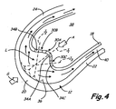
- FIG. 4 is a close up view of stationary turbine vane 10 of FIG. 3 showing leading edge portions of airfoil 12 and baffle 18.
- Airfoil 12 includes leading edge 20, pressure side 22 and suction side 24.
- Baffle 18 includes divot 30, which is comprised of sections 30A - 30C, and cooling holes 34, which include cooling holes 34A - 34C.
- Wall segments 30A-30C are curved, and segment 30A comprises an elbow segment connecting segments 30B and 30C.
- Baffle 18 is positioned within cavity 36 of airfoil 12 to form cooling circuit 40. Cooling air A is provided to supply duct 38 within baffle 18. Hot gas G impinges upon and heats airfoil 12. In particular, leading edge 20 of airfoil 12 comprises a hotspot having localized increases in temperature from hot gas G, as compared to other surfaces on airfoil 12. As such, divot 30 is provided along the leading edge portion of baffle 18 to focus cooling air A at leading edge 20. Cooling holes 34A - 34C of divot 30 direct air jets J 1 - J 3 onto airfoil 12.
- Cooling holes are typically drilled, or otherwise produced, to extend perpendicularly through the walls of airfoil cooling baffles. As such, jets of cooling air typically radiate from the baffle at trajectories normal to the baffle surface.
- the walls of baffles are typically thin such that it is difficult to alter the trajectory of air passing through cooling holes extending through the baffle.
- the thickness of baffle 18 is on the order of tens of thousandths of an inch (less than a millimeter) thick. As such, an angled hole through a baffle produces little if any change in the trajectory of air traveling though the hole. Angled cooling holes thus perform substantially similarly to perpendicular cooling holes in thin baffles.
- baffles due to their light weight, inexpensiveness, and manufacturability. Furthermore, the tolerances required of baffles prohibit casting of thick, heavier weight structures into which effective angled cooling holes could be machined. Divots of the present invention permit angling of cooling holes jets J 1 - J 3 in thin-walled baffles.
- Cooling holes 34A - 34C are disposed along baffle 18 at positions equidistant from either the inner diameter end or the outer diameter end of baffle 18 such that jets J 1 - J 3 are located in a common plane. Jets J 1 - J 3 will impact airfoil 12 at the same radial position along vane 10. Cooling holes 34 are thus disposed in a plurality of parallel columns and rows, as shown in FIG. 2 . However, the cooling holes could be staggered so as to form columns with offset rows. Cooling holes 34A - 34C are sized such that stagnation of cooling air A within duct 38 is prevented.
- cooling holes 34A - 34C are sized to maintain the pressure within duct 38 above that of cavity 36 such that metering of air A through holes 34A - 34C is maintained.
- cooling holes 34A - 34C are approximately equal in size to each other.
- cooling holes along other longitudinal positions of baffle 18 may be larger or smaller than cooling holes 34A - 34C.
- large cooling holes may be used near hotspots, while smaller cooling holes may be used at cooler positions along airfoil 12.
- cooling holes 34, as well as cooling holes 32 ( FIG. 2 ) and other cooling holes within baffle 18 do not produce a large pressure drop across baffle 18.
- Walls 30A - 30C of divot 30 are curved to focus jets J 1 - J 3 at common location L to promote advanced cooling modes. Jets J 2 and J 3 are directed out of baffle 18 at angles oblique to the profile of baffle 18 and oblique to the interior surface of airfoil 12. Jet J 1 is directed out of baffle 18 normal the profile of baffle 18 and the interior surface of airfoil 12 to intersect jets J 2 and J 3 at common location L. In the configuration shown, location L is positioned approximately midway between baffle 18 and airfoil 12. In other embodiments, location L is positioned on the surface of airfoil 12 or outside of airfoil 12.
- jets J 1 - J 3 impact airfoil 12 at a common location that has a smaller width as compared to cooling holes that would be disposed along a baffle not having divot 30 along the leading edge.
- a greater volume of cooling air is concentrated at or near leading edge 20.
- Angling of cooling holes 34A - 34C towards each other also promotes entrainment and mixing of jets J 1 - J 3 as the jets travel toward leading edge 20 of airfoil 12.
- Entrainment of jets J 1 - J 3 forms turbulence that increases the cooling effect on airfoil 12.
- both impingement cooling and conductive cooling is enhanced at leading edge 20 to remove heat from airfoil 12.
- cooling of airfoil 12 can be further enhanced by providing turbulators along the interior surface of airfoil 12. Conductive cooling is continuously provided as jets J 1 - J 3 continue through cooling circuit 40 to discharge slot 44 ( FIG. 3 ). As such, divots of the present invention permit aiming of cooling holes in thin-walled and easy to manufacture baffles to enhance cooling of airfoils at hotspots.
Description
- The present invention is related to cooling of airfoils for gas turbine engines and, more particularly, to baffle inserts for impingement cooling of airfoil vanes. Gas turbine engines operate by passing a volume of high energy gases through a series of compressors and turbines in order to produce rotational shaft power. The shaft power is used to turn a turbine for driving a compressor to provide air to a combustion process to generate the high energy gases. Additionally, the shaft power is used to power a secondary turbine to, for example, drive a generator for producing electricity, or to produce high momentum gases for producing thrust. Each compressor and turbine comprises a plurality of stages of vanes and blades, each having an airfoil, with the rotating blades pushing air past the stationary vanes. In general, stators redirect the trajectory of the air coming off the rotors for flow into the next stage. In the compressor, stators convert kinetic energy of moving air into pressure, while, in the turbine, stators accelerate pressurized air to extract kinetic energy.
- In order to produce gases having sufficient energy to drive both the compressor and the secondary turbine, it is necessary to compress the air to elevated temperatures and to combust the air, which again increases the temperature. Thus, the vanes and blades are subjected to extremely high temperatures, often times exceeding the melting point of the alloys used to make the airfoils. In particular, the leading edge of an airfoil, which impinges most directly with the heated gases, is heated to the highest temperature along the airfoil. The airfoils are maintained at temperatures below their melting point by, among other things, cooling the airfoils with a supply of relatively cooler air that is typically siphoned from a compressor. The cooling air is directed into the blade or vane to provide cooling of the airfoil through various modes including impingement cooling. Specifically, the cooling air is passed into an interior of the airfoil to remove heat from the alloy. The cooling air is subsequently discharged through cooling holes in the airfoil to pass over the outer surface of the airfoil to prevent the hot gases from contacting the vane or blade. In other configurations, the cooling air is typically directed into a baffle disposed within a vane interior and having a plurality cooling holes. Cooling air from the cooling holes impinges on an interior surface of the vane before exiting the vane at a trailing edge discharge slot.
- Due to the extremely thin nature of the baffle, it is difficult to control the cooling air as it leaves the baffle. Various baffle designs have been developed to better distribute cooling air along the interior surfaces of the vane. Many previous baffle designs require extensive fabricating, shaping and assembly steps, which increase manufacturing time and expense. There is, therefore, a need for a simpler baffle design that is easy to produce and cost effective.
-
US 2873944 discloses the features of the pre-characterising portion of claim 1. - The present invention provides a baffle insert for an internally cooled airfoil, the baffle insert comprising: a liner having a continuous perimeter formed to shape a hollow body having a first end and a second end; a divoted segment of the hollow body positioned between the first end and the second end; and a plurality of cooling holes positioned on the divoted segment to aim cooling air exiting the baffle insert, wherein the divoted segment comprises an elongate, longitudinal depression in the hollow body extending between the first end and the second end, wherein the depression comprises: a first curved segment having a first column of cooling holes; a second curved segment having a second column of cooling holes; and an elbow segment connecting the first curved segment with the second curved segment and having a third column of cooling holes, wherein the first and second curved segments are curved to direct air through the first and second columns of cooling holes at angles oblique to an interior surface of the airfoil, and characterised in that: the elbow segment is curved to direct air through the third column of cooling holes at an angle normal to the profile of the baffle and the interior surface of the airfoil, and the first and second curved segments and the elbow segment are curved to focus cooling air from the first, second and third columns of cooling holes such that the cooling air from the first, second and third columns of cooling holes intersects at a common location.
-
-
FIG. 1 is a perspective view of a stationary turbine vane showing an airfoil baffle having divots of the present invention. -
FIG. 2 is a partially broken away perspective view of the stationary turbine vane ofFIG. 1 showing cooling holes positioned along the divots of the airfoil baffle. -
FIG. 3 is a cross-sectional view of the stationary turbine vane ofFIG. 1 showing a cooling circuit between the turbine vane and the airfoil baffle for cooling air from the cooling holes. -
FIG. 4 is a close up view of the stationary turbine vane ofFIG. 3 showing leading edge portions of the turbine vane and the airfoil baffle. -
FIG. 1 shows a perspective view ofstationary turbine vane 10 havingairfoil 12, outerdiameter vane shroud 14, innerdiameter vane shroud 16 andbaffle 18. Airfoil 12 includes leadingedge 20,pressure side 22,suction side 24 andtrailing edge 26. Baffle 18 includesdivot 28. - Turbine vane 10 is a stationary vane that receives high energy gas G in a turbine section of a gas turbine engine. In other embodiments,
vane 10 is used in a compressor section of a gas turbine engine. The outer diameter end ofairfoil 12 mates withshroud 14 and the inner diameter end ofairfoil 12 mates withshroud 16.Shrouds airfoil 12 is supported.Outer diameter shrouds 14 are connected using, for example, threaded fasteners and suspended from an outer diameter engine case.Inner diameter shrouds 16 are similarly connected and supported by inner diameter support struts. Turbine vanes 10 operate to increase the efficiency of the gas turbine engine in which they are installed. - Vane shroud 14 and vane shroud 16 increase the efficiency of the gas turbine engine by forming outer and inner boundaries for the flow of gas G through the gas turbine engine. Vane shrouds 14 and 16 prevent escape of gas G from the gas turbine engine such that more air is available for performing work. The shape of
vane 10 also increases the efficiency of the gas turbine engine.Vane 10 generally functions to redirect the trajectory of gas G coming from a combustor section or a blade of an upstream turbine stage to a blade of a downstream turbine stage.Pressure side 22 andsuction side 24 redirect the flow of gas G received at leadingedge 20 such that, after passing bytrailing edge 26, the incidence of gas G on the subsequent rotor blade stage is optimized. As such, more work can be extracted from the interaction of gas G with downstream blades. - The efficiency of the gas turbine engine is also improved by increasing the temperature to which
vane 10 can be subjected. In one embodiment,vane 10 comprises a high pressure turbine vane that is positioned downstream of a combustor section of a gas turbine engine to receive hot combustion gas.Airfoil 12 is, therefore, subjected to a concentrated, steady stream of combustion gas G during operation of the gas turbine engine. The extremely elevated temperatures of combustion gas G often exceed the melting point of thematerial forming vane 10. Airfoil 12 is therefore cooled using cooling air provided by, for example, relatively cooler air bled from a compressor section within the gas turbine engine. The cooling air is directed intobaffle 18 where small cooling holes distribute the cooling air to perform impingement cooling on the interior ofairfoil 12.Divot 28 focuses a portion of the cooling air onto hotspots ofairfoil 12. -
FIG. 2 is a partially broken away perspective view ofstationary turbine vane 10 ofFIG. 1 showing the position ofpressure side divot 28 and leadingedge divot 30 ofbaffle 18 with respect toairfoil 12.Pressure side divot 28 and leadingedge divot 30 includecooling holes 32 andcooling holes 34, respectively.Airfoil 12 comprises a thin-walled hollow structure that formsinternal cavity 36 for receivingbaffle 18 betweenshrouds air supply duct 38. In the embodiment shown,outer diameter shroud 14 includes an opening to receivebaffle 18, whileinner diameter shroud 16 is closed to supportbaffle 18. Baffle 18 is typically joined, such as by welding, to eitherouter diameter shroud 14 orinner diameter shroud 16, while remaining free at the opposite end. The ends ofbaffle 18 are open to receive cooling air A for coolingairfoil 12 from temperatures produced by hot gas G. In other embodiments, however, one end ofbaffle 18 is closed or semi-closed to assist in forcing cooling air A outcooling holes baffle 18 is the end not connected toshrouds - Cooling air A enters
supply duct 38 ofbaffle 18, passes throughcooling holes internal cavity 36 to perform impingement cooling on the interior ofairfoil 12.Cooling holes divots Divots baffle 18 that extend from the outer diameter end to the inner diameter end ofbaffle 18. As such,cooling holes airfoil 12. In other embodiments, however,divots baffle 18.Divots airfoil 12 at different angles. Specifically, cooling holes 32 comprise a series of three columns disposed along surfaces ofdivot 28. Likewise, cooling holes 34 comprise a series of three columns disposed along surfaces ofdivot 30. In other embodiments, only one or two columns of cooling holes may be used. For example, a single column could extend along the center ofdivot 28, or a pair of columns could extend along the sides ofdivot 28. Additionally, the spacing between cooling holes in each column can be varied to direct more cooling air to hotter portions ofairfoil 12. The surfaces ofdivots airfoil 12. As such,divots airfoil 12 and need not be used together. Various divots can be positioned on any surface around the perimeter ofbaffle 18, includingsuction side 24. - Hot gas G flows across
vane 10, impinges leadingedge 20 and flows acrosssuction side 22 andpressure side 24 ofairfoil 12. The flow dynamics of gas G produced by the geometry ofairfoil 12 may result in a particular portion ofairfoil 12 developing a hotspot where the temperature rises to levels above where the temperature is at other places alongairfoil 12. For example, the specific design ofairfoil 12 may lead to hotspots based on the manner with whichpressure side 22 engages gas G to perform work. Also, as with the case of all airfoil designs, leadingedge 20 ofairfoil 12 is particularly susceptible to hotspots due to interaction with the hottest portions of the flow of gas G. Direct impingement of gas G on leadingedge 20 also inhibits the formation of turbulent flow acrossairfoil 12 that provides a buffer against gas G. As such, it is desirable to deliver additional cooling air A to hotspots onairfoil 12.Divot 28 is positioned on the pressure side ofbaffle 18 to deliver cooling air A to a hotspot along a longitudinal section ofairfoil 12 at a specific chord-wise position onpressure side 22.Divot 30 is positioned on the leading edge ofbaffle 18 to deliver cooling air A to a hotspot along a longitudinal section ofairfoil 12 at leadingedge 20. The contours ofdivot 28 anddivot 30 aim the columns of cooling holes 32 and 34, respectively, to the hotspots to reduce the temperature ofairfoil 12. -
FIG. 3 is a cross-sectional view ofstationary vane 10 ofFIG. 1 taken at section 3 - 3showing cooling circuit 40 betweenairfoil 12 andbaffle 18.Airfoil 12 includes leadingedge 20,pressure side 22,suction side 24, trailingedge 26, pedestals 42A - 42D anddischarge slot 44.Baffle 18 includespressure side divot 28, leadingedge divot 30, pressure side cooling holes 32 and leading edge cooling holes 34.Baffle 18 is inserted intointernal cavity 36 and is maintained at a minimum distance fromairfoil 12 by standoffs (not shown). Hot gas G, such as from a combustor of a gas turbine engine, impinges leadingedge 20 ofairfoil 12. Pressurized cooling air A, such as relatively cooler air from a compressor of the gas turbine engine, is directed intosupply duct 38 ofbaffle 18. -
Airfoil 12 is fabricated, typically by casting, as a thin-walled structure in the shape of an airfoil. The leading edge portions ofpressure side 22 andsuction side 24 are displaced from each other to forminternal cavity 36. In the embodiment shown,internal cavity 36 comprises a single space, but inother embodiments cavity 36 may be divided into segments using integral partitions.Internal cavity 36 continually narrows asinternal cavity 36 progresses from leadingedge 20 toward trailingedge 26.Pressure side 22 andsuction side 24 do not touch at trailingedge 26 such thatdischarge slot 44 is formed. The trailing edge portions ofpressure side 22 andsuction side 24 are supported withpedestals 42A - 42D.Pedestals 42A - 42D typically comprise small-diameter cylindrical stanchions that span the distance betweenpressure side 22 andsuction side 24.Pedestals 42A - 42D are staggered so as to form an anfractuous flow path betweencavity 36 anddischarge slot 44. -
Baffle 18 is formed into the general shape of an airfoil so as to match the shape ofinternal cavity 36. For example, baffle 18 includes a leading edge profile that tracks with leadingedge 20. In embodiments wherecavity 36 is divided with partitions, a baffle can be provided to each segment ofcavity 36. In such embodiments, the profile ofbaffle 18 may have other configurations, such as having a flat surface to track with a partition. A plurality of divots can be positioned along any surface of a baffle to cool a plurality of unique hotspots. The perimeter ofbaffle 18 is continuous such that a simple hoop-shaped structure is formed. The walls ofbaffle 18 are shaped such thatduct 38 comprises a single chamber. For example,divots duct 38 into different flow paths. The inner and outer diameter ends ofbaffle 18 are open such that shrouds 14 and 16 (FIG. 2 ) control flow of cooling air A intoduct 38. Configured as such,baffle 18 is minimally shaped to facilitate easy manufacture. -
Baffle 18 is typically formed from thin sheet metal. First, a pattern is cut from a piece of flat sheet metal. Next, the pattern is bent to form a rough-shaped hollow body. The ends of the hollow body are welded such that the baffle has a continuous perimeter. The shape of the hollow body is then finished using a series of die-shaping steps which give the hollow body the general shape of an airfoil. Other features, such as standoffs and divots, can be easily formed into the sheet metal using the die-shaping steps. The divots are positioned away from the welded seam such that the divots are seamless. In one embodiment, the welded seam is positioned away from the leading edge ofbaffle 18 such thatleading edge divot 30 ofbaffle 18 is seamless. The top and bottom of the hollow, airfoil-shaped structure can then be trimmed to givebaffle 18 the desired height for use with a specific vane. If desired, an end ofbaffle 18 can be closed or semi-closed by crimping and then welded shut if fully closed. Plates can then be welded to each end to facilitate connection withshrouds baffle 18 using any conventional method. -
Baffle 18 is disposed withinairfoil 12 such thatcooling circuit 40 is formed withincavity 36. Standoffs, which may be integrally formed withbaffle 18 orairfoil 12, comprise small pads that extend acrosscircuit 40 to inhibit movement ofbaffle 18 withincavity 36.Cavity 36 withinairfoil 12 is open toduct 38 withinbaffle 18 through cooling holes 32 and 34. As such, a pressure differential is produced betweencavity 36 andduct 38 when cooling air A is directed intobaffle 18. Cooling air A is thus pushed through cooling holes 32 and 34 intocavity 36. Cooling holes 34 shape cooling air A into a plurality of small air jets J. Similarly, jets of cooling airA enter cavity 36 through cooling holes 32, but illustration of such air jets is omitted for clarity.Baffle 18 typically also includes other cooling holes (not shown) that are distributed over the entirety ofbaffle 18 for cooling of portions ofairfoil 12 away fromdivots circuit 40 whereby the air cools the interior surface ofairfoil 12. Air jets J entercavity 36, flow around the outside ofbaffle 18, and are dispersed intopedestals 42A - 42D. Air jets J flow above and belowpedestals 42A - 42D as they migrate towarddischarge slot 44 where the air is released into hot gas G flowing aroundairfoil 12. Air jets J mix withincavity 36 near leadingedge 20 to perform various modes of cooling onairfoil 12. -
FIG. 4 is a close up view ofstationary turbine vane 10 ofFIG. 3 showing leading edge portions ofairfoil 12 andbaffle 18.Airfoil 12 includes leadingedge 20,pressure side 22 andsuction side 24.Baffle 18 includesdivot 30, which is comprised ofsections 30A - 30C, and cooling holes 34, which includecooling holes 34A - 34C.Wall segments 30A-30C are curved, andsegment 30A comprises an elbowsegment connecting segments -
Baffle 18 is positioned withincavity 36 ofairfoil 12 to form coolingcircuit 40. Cooling air A is provided to supplyduct 38 withinbaffle 18. Hot gas G impinges upon and heatsairfoil 12. In particular, leadingedge 20 ofairfoil 12 comprises a hotspot having localized increases in temperature from hot gas G, as compared to other surfaces onairfoil 12. As such,divot 30 is provided along the leading edge portion ofbaffle 18 to focus cooling air A at leadingedge 20. Cooling holes 34A - 34C ofdivot 30 direct air jets J1 - J3 ontoairfoil 12. - Cooling holes are typically drilled, or otherwise produced, to extend perpendicularly through the walls of airfoil cooling baffles. As such, jets of cooling air typically radiate from the baffle at trajectories normal to the baffle surface. The walls of baffles are typically thin such that it is difficult to alter the trajectory of air passing through cooling holes extending through the baffle. For example, the thickness of
baffle 18 is on the order of tens of thousandths of an inch (less than a millimeter) thick. As such, an angled hole through a baffle produces little if any change in the trajectory of air traveling though the hole. Angled cooling holes thus perform substantially similarly to perpendicular cooling holes in thin baffles. It is, however, desirable to use thin-walled baffles due to their light weight, inexpensiveness, and manufacturability. Furthermore, the tolerances required of baffles prohibit casting of thick, heavier weight structures into which effective angled cooling holes could be machined. Divots of the present invention permit angling of cooling holes jets J1 - J3 in thin-walled baffles. - Cooling holes 34A - 34C are disposed along
baffle 18 at positions equidistant from either the inner diameter end or the outer diameter end ofbaffle 18 such that jets J1 - J3 are located in a common plane. Jets J1 - J3 will impactairfoil 12 at the same radial position alongvane 10. Cooling holes 34 are thus disposed in a plurality of parallel columns and rows, as shown inFIG. 2 . However, the cooling holes could be staggered so as to form columns with offset rows. Cooling holes 34A - 34C are sized such that stagnation of cooling air A withinduct 38 is prevented. For example, cooling holes 34A - 34C are sized to maintain the pressure withinduct 38 above that ofcavity 36 such that metering of air A throughholes 34A - 34C is maintained. In one embodiment, cooling holes 34A - 34C are approximately equal in size to each other. However, cooling holes along other longitudinal positions ofbaffle 18 may be larger or smaller than coolingholes 34A - 34C. For example, large cooling holes may be used near hotspots, while smaller cooling holes may be used at cooler positions alongairfoil 12. Thus, cooling holes 34, as well as cooling holes 32 (FIG. 2 ) and other cooling holes withinbaffle 18 do not produce a large pressure drop acrossbaffle 18. -
Walls 30A - 30C ofdivot 30 are curved to focus jets J1 - J3 at common location L to promote advanced cooling modes. Jets J2 and J3 are directed out ofbaffle 18 at angles oblique to the profile ofbaffle 18 and oblique to the interior surface ofairfoil 12. Jet J1 is directed out ofbaffle 18 normal the profile ofbaffle 18 and the interior surface ofairfoil 12 to intersect jets J2 and J3 at common location L. In the configuration shown, location L is positioned approximately midway betweenbaffle 18 andairfoil 12. In other embodiments, location L is positioned on the surface ofairfoil 12 or outside ofairfoil 12. In all embodiments, however, jets J1 - J3 impact airfoil 12 at a common location that has a smaller width as compared to cooling holes that would be disposed along a baffle not havingdivot 30 along the leading edge. Thus, a greater volume of cooling air is concentrated at or near leadingedge 20. Angling ofcooling holes 34A - 34C towards each other also promotes entrainment and mixing of jets J1 - J3 as the jets travel toward leadingedge 20 ofairfoil 12. Entrainment of jets J1 - J3 forms turbulence that increases the cooling effect onairfoil 12. Thus, both impingement cooling and conductive cooling is enhanced at leadingedge 20 to remove heat fromairfoil 12. In other embodiments, cooling ofairfoil 12 can be further enhanced by providing turbulators along the interior surface ofairfoil 12. Conductive cooling is continuously provided as jets J1 - J3 continue throughcooling circuit 40 to discharge slot 44 (FIG. 3 ). As such, divots of the present invention permit aiming of cooling holes in thin-walled and easy to manufacture baffles to enhance cooling of airfoils at hotspots. - While the invention has been described with reference to an exemplary embodiment(s), it will be understood by those skilled in the art that various changes may be made and equivalents may be substituted for elements thereof without departing from the scope of the invention. In addition, many modifications may be made to adapt a particular situation or material to the teachings of the invention without departing from the essential scope thereof. Therefore, it is intended that the invention not be limited to the particular embodiment(s) disclosed, but that the invention will include all embodiments falling within the scope of the appended claims.
Claims (15)
- A baffle insert (18) for an internally cooled airfoil (10), the baffle insert comprising:a liner having a continuous perimeter formed to shape a hollow body having a first end and a second end;a divoted segment (28,30) of the hollow body positioned between the first end and the second end; anda plurality of cooling holes (32,34) positioned on the divoted segment to aim cooling air exiting the baffle insert,wherein the divoted segment (28,30) comprises an elongate, longitudinal depression in the hollow body extending between the first end and the second end,wherein the depression comprises:a first curved segment (30B) having a first column of cooling holes;a second curved segment (30C) having a second column of cooling holes; andan elbow segment (30A) connecting the first curved segment with the second curved segment and having a third column of cooling holes,wherein the first and second curved segments (30B, 30C) are curved to direct air through the first and second columns of cooling holes at angles oblique to an interior surface of the airfoil,and characterised in that:the elbow segment (30A) is curved to direct air through the third column of cooling holes at an angle normal to the profile of the baffle and the interior surface of the airfoil, andthe first and second curved segments (30B, 30C) and the elbow segment (30A) are curved to focus cooling air from the first, second and third columns of cooling holes such that the cooling air from the first, second and third columns of cooling holes intersects at a common location (L).
- The baffle insert of claim 1 wherein the elbow segment (30A) is disposed along a leading edge of the hollow body.
- The baffle insert of claim 1 or 2 wherein the first and second columns of cooling holes (32,34) extend approximately perpendicularly through the curved segments of the depression so as to discharge cooling air at an oblique angle with respect to a profile of the liner.
- The baffle insert of claim 1, 2 or 3 wherein the cooling holes (32,34) of the first column, the second column and the third column are approximately equally sized and disposed in parallel rows.
- The baffle insert of claim 1, 2, 3 or 4 wherein the first and second curved segments (30B,30C) and the elbow segment (30A) are disposed about an arc to focus cooling air at a common location to promote mixing and entraining of the cooling air.
- The baffle insert of any preceding claim wherein at least one of the first and second ends of the continuous perimeter of the hollow body are open and walls of the hollow body are not touching such that a single, continuous cooling passage (40) is formed within the baffle insert.
- The baffle insert of any preceding claim and further comprising a plurality of divoted segments (28,30) each shaped to focus cooling air at different common locations.
- The baffle insert of any preceding claim wherein the divoted segment comprises a seamless portion of the hollow liner body.
- An internally cooled airfoil (10) comprising:an outer airfoil body (12) shaped to form a leading edge (20), a trailing edge (26), a pressure side (22) and a suction side (24) surrounding an internal cooling channel (36); anda baffle insert (18) as claimed in any preceding claim disposed within the internal cooling channel, the baffle insert comprising:said liner having said continuous perimeter shaped to correspond to the shape of the internal cooling channel and to form a cooling air supply duct;said divoted segment (28,30) disposed along the liner; andsaid plurality of cooling holes (32,34) positioned on the divoted segment to aim cooling air from the supply duct onto the outer airfoil body at a common location.
- The internally cooled airfoil of claim 9 wherein the baffle insert (18) is displaced from the outer airfoil body (12) along the entire continuous perimeter of the liner such that a cooling circuit is formed between the outer airfoil body and the baffle insert.
- The internally cooled airfoil of claim 9 or 10 wherein the common location comprises a hotspot on the outer airfoil body (12).
- The internally cooled airfoil of claim 9, 10 or 11 wherein the outer airfoil body (12) comprises a stationary vane (10) comprising:an inner diameter vane shroud (16); andan outer diameter vane shroud (14);wherein the baffle insert (18) is supported within the internal cooling channel by the inner diameter vane shroud and the outer diameter vane shroud.
- The apparatus of any preceding claim wherein the baffle insert (18) is open at inner and outer diameter ends to form a hoop-like structure approximating a shape of an airfoil.
- The apparatus of any preceding claim wherein the baffle is formed from sheet metal.
- The apparatus of any of claims 3 to 14 wherein the third column of cooling holes extends perpendicularly through the elbow segments.
Applications Claiming Priority (1)
| Application Number | Priority Date | Filing Date | Title |
|---|---|---|---|
| US12/403,976 US8152468B2 (en) | 2009-03-13 | 2009-03-13 | Divoted airfoil baffle having aimed cooling holes |
Publications (3)
| Publication Number | Publication Date |
|---|---|
| EP2228517A2 EP2228517A2 (en) | 2010-09-15 |
| EP2228517A3 EP2228517A3 (en) | 2013-03-13 |
| EP2228517B1 true EP2228517B1 (en) | 2016-05-04 |
Family
ID=42105906
Family Applications (1)
| Application Number | Title | Priority Date | Filing Date |
|---|---|---|---|
| EP10250478.4A Active EP2228517B1 (en) | 2009-03-13 | 2010-03-15 | A cooled airfoil and an impingement baffle insert therefor |
Country Status (2)
| Country | Link |
|---|---|
| US (1) | US8152468B2 (en) |
| EP (1) | EP2228517B1 (en) |
Families Citing this family (39)
| Publication number | Priority date | Publication date | Assignee | Title |
|---|---|---|---|---|
| US9347324B2 (en) | 2010-09-20 | 2016-05-24 | Siemens Aktiengesellschaft | Turbine airfoil vane with an impingement insert having a plurality of impingement nozzles |
| US9403208B2 (en) | 2010-12-30 | 2016-08-02 | United Technologies Corporation | Method and casting core for forming a landing for welding a baffle inserted in an airfoil |
| US20130223987A1 (en) * | 2012-02-29 | 2013-08-29 | Scott Stafford | Turbine Nozzle Insert |
| CN104204412B (en) * | 2012-03-22 | 2016-09-28 | 通用电器技术有限公司 | Turbo blade |
| US9296039B2 (en) | 2012-04-24 | 2016-03-29 | United Technologies Corporation | Gas turbine engine airfoil impingement cooling |
| US9243502B2 (en) | 2012-04-24 | 2016-01-26 | United Technologies Corporation | Airfoil cooling enhancement and method of making the same |
| US20130280081A1 (en) * | 2012-04-24 | 2013-10-24 | Mark F. Zelesky | Gas turbine engine airfoil geometries and cores for manufacturing process |
| US20140075947A1 (en) * | 2012-09-18 | 2014-03-20 | United Technologies Corporation | Gas turbine engine component cooling circuit |
| US10173264B2 (en) * | 2013-03-15 | 2019-01-08 | United Technologies Corporation | Additive manufacturing baffles, covers, and dies |
| US20140341723A1 (en) * | 2013-03-15 | 2014-11-20 | General Electric Company | Gas turbine vane insert to control particulate deposition |
| US10280793B2 (en) | 2013-09-18 | 2019-05-07 | United Technologies Corporation | Insert and standoff design for a gas turbine engine vane |
| US9927123B2 (en) | 2013-10-24 | 2018-03-27 | United Technologies Corporation | Fluid transport system having divided transport tube |
| US10012106B2 (en) | 2014-04-03 | 2018-07-03 | United Technologies Corporation | Enclosed baffle for a turbine engine component |
| US9988913B2 (en) | 2014-07-15 | 2018-06-05 | United Technologies Corporation | Using inserts to balance heat transfer and stress in high temperature alloys |
| EP3000970B1 (en) * | 2014-09-26 | 2019-06-12 | Ansaldo Energia Switzerland AG | Cooling scheme for the leading edge of a turbine blade of a gas turbine |
| US9879554B2 (en) | 2015-01-09 | 2018-01-30 | Solar Turbines Incorporated | Crimped insert for improved turbine vane internal cooling |
| US9810084B1 (en) | 2015-02-06 | 2017-11-07 | United Technologies Corporation | Gas turbine engine turbine vane baffle and serpentine cooling passage |
| US9849510B2 (en) | 2015-04-16 | 2017-12-26 | General Electric Company | Article and method of forming an article |
| US9976441B2 (en) | 2015-05-29 | 2018-05-22 | General Electric Company | Article, component, and method of forming an article |
| FR3039199B1 (en) * | 2015-07-20 | 2019-12-13 | Safran Helicopter Engines | BLADE OF HIGH PRESSURE DISTRIBUTOR WITH A VARIABLE GEOMETRY INSERT |
| US10184341B2 (en) | 2015-08-12 | 2019-01-22 | United Technologies Corporation | Airfoil baffle with wedge region |
| US10012092B2 (en) | 2015-08-12 | 2018-07-03 | United Technologies Corporation | Low turn loss baffle flow diverter |
| US10087776B2 (en) | 2015-09-08 | 2018-10-02 | General Electric Company | Article and method of forming an article |
| US10739087B2 (en) | 2015-09-08 | 2020-08-11 | General Electric Company | Article, component, and method of forming an article |
| US10253986B2 (en) * | 2015-09-08 | 2019-04-09 | General Electric Company | Article and method of forming an article |
| US20170130589A1 (en) * | 2015-11-05 | 2017-05-11 | General Electric Company | Article, component, and method of cooling a component |
| US10370979B2 (en) | 2015-11-23 | 2019-08-06 | United Technologies Corporation | Baffle for a component of a gas turbine engine |
| US10156147B2 (en) | 2015-12-18 | 2018-12-18 | United Technologies Corporation | Method and apparatus for cooling gas turbine engine component |
| US10450880B2 (en) | 2016-08-04 | 2019-10-22 | United Technologies Corporation | Air metering baffle assembly |
| US10408082B2 (en) * | 2016-11-17 | 2019-09-10 | United Technologies Corporation | Airfoil with retention pocket holding airfoil piece |
| US20190017392A1 (en) * | 2017-07-13 | 2019-01-17 | General Electric Company | Turbomachine impingement cooling insert |
| US10633980B2 (en) * | 2017-10-03 | 2020-04-28 | United Technologies Coproration | Airfoil having internal hybrid cooling cavities |
| US10704398B2 (en) * | 2017-10-03 | 2020-07-07 | Raytheon Technologies Corporation | Airfoil having internal hybrid cooling cavities |
| US20190101009A1 (en) * | 2017-10-03 | 2019-04-04 | United Technologies Corporation | Airfoil having internal hybrid cooling cavities |
| US10626734B2 (en) | 2017-10-03 | 2020-04-21 | United Technologies Corporation | Airfoil having internal hybrid cooling cavities |
| US10626733B2 (en) | 2017-10-03 | 2020-04-21 | United Technologies Corporation | Airfoil having internal hybrid cooling cavities |
| US10526898B2 (en) * | 2017-10-24 | 2020-01-07 | United Technologies Corporation | Airfoil cooling circuit |
| US10738620B2 (en) | 2018-04-18 | 2020-08-11 | Raytheon Technologies Corporation | Cooling arrangement for engine components |
| US10774657B2 (en) | 2018-11-23 | 2020-09-15 | Raytheon Technologies Corporation | Baffle assembly for gas turbine engine components |
Family Cites Families (28)
| Publication number | Priority date | Publication date | Assignee | Title |
|---|---|---|---|---|
| US2873944A (en) | 1952-09-10 | 1959-02-17 | Gen Motors Corp | Turbine blade cooling |
| US2994124A (en) | 1955-10-03 | 1961-08-01 | Gen Electric | Clad cermet body |
| US3806275A (en) * | 1972-08-30 | 1974-04-23 | Gen Motors Corp | Cooled airfoil |
| US4153386A (en) | 1974-12-11 | 1979-05-08 | United Technologies Corporation | Air cooled turbine vanes |
| US4519745A (en) | 1980-09-19 | 1985-05-28 | Rockwell International Corporation | Rotor blade and stator vane using ceramic shell |
| DE3110098C2 (en) | 1981-03-16 | 1983-03-17 | MTU Motoren- und Turbinen-Union München GmbH, 8000 München | Turbine guide vane for gas turbine engines |
| DE3629910A1 (en) | 1986-09-03 | 1988-03-17 | Mtu Muenchen Gmbh | METAL HOLLOW COMPONENT WITH A METAL INSERT, IN PARTICULAR TURBINE BLADE WITH COOLING INSERT |
| JPH0663442B2 (en) * | 1989-09-04 | 1994-08-22 | 株式会社日立製作所 | Turbine blades |
| FR2659689B1 (en) | 1990-03-14 | 1992-06-05 | Snecma | INTERNAL COOLING CIRCUIT OF A TURBINE STEERING BLADE. |
| GB2242941B (en) | 1990-04-11 | 1994-05-04 | Rolls Royce Plc | A cooled gas turbine engine aerofoil |
| US5383766A (en) | 1990-07-09 | 1995-01-24 | United Technologies Corporation | Cooled vane |
| US5405242A (en) | 1990-07-09 | 1995-04-11 | United Technologies Corporation | Cooled vane |
| JPH07279612A (en) | 1994-04-14 | 1995-10-27 | Mitsubishi Heavy Ind Ltd | Heavy oil burning gas turbine cooling blade |
| US5591002A (en) | 1994-08-23 | 1997-01-07 | General Electric Co. | Closed or open air cooling circuits for nozzle segments with wheelspace purge |
| US6050777A (en) | 1997-12-17 | 2000-04-18 | United Technologies Corporation | Apparatus and method for cooling an airfoil for a gas turbine engine |
| EP1409926B1 (en) | 1999-08-03 | 2004-11-03 | Siemens Aktiengesellschaft | Baffle cooling device |
| GB0001679D0 (en) * | 2000-01-26 | 2000-03-15 | Rolls Royce Plc | Method of producing a lining artefact |
| DE10004128B4 (en) * | 2000-01-31 | 2007-06-28 | Alstom Technology Ltd. | Air-cooled turbine blade |
| JP2001304551A (en) * | 2000-04-26 | 2001-10-31 | Toshiba Corp | Method for making combustion liner for gas turbine |
| US6554563B2 (en) | 2001-08-13 | 2003-04-29 | General Electric Company | Tangential flow baffle |
| US6742991B2 (en) * | 2002-07-11 | 2004-06-01 | Mitsubishi Heavy Industries, Ltd. | Turbine blade and gas turbine |
| US6955522B2 (en) | 2003-04-07 | 2005-10-18 | United Technologies Corporation | Method and apparatus for cooling an airfoil |
| FR2856729B1 (en) * | 2003-06-30 | 2005-09-23 | Snecma Moteurs | COOLING AUBES OF GAS TURBINE ENGINE. |
| US7118326B2 (en) | 2004-06-17 | 2006-10-10 | Siemens Power Generation, Inc. | Cooled gas turbine vane |
| US7465154B2 (en) * | 2006-04-18 | 2008-12-16 | United Technologies Corporation | Gas turbine engine component suction side trailing edge cooling scheme |
| US7497655B1 (en) * | 2006-08-21 | 2009-03-03 | Florida Turbine Technologies, Inc. | Turbine airfoil with near-wall impingement and vortex cooling |
| US8096758B2 (en) * | 2008-09-03 | 2012-01-17 | Siemens Energy, Inc. | Circumferential shroud inserts for a gas turbine vane platform |
| US8231329B2 (en) * | 2008-12-30 | 2012-07-31 | General Electric Company | Turbine blade cooling with a hollow airfoil configured to minimize a distance between a pin array section and the trailing edge of the air foil |
-
2009
- 2009-03-13 US US12/403,976 patent/US8152468B2/en active Active
-
2010
- 2010-03-15 EP EP10250478.4A patent/EP2228517B1/en active Active
Also Published As
| Publication number | Publication date |
|---|---|
| US20100232946A1 (en) | 2010-09-16 |
| US8152468B2 (en) | 2012-04-10 |
| EP2228517A2 (en) | 2010-09-15 |
| EP2228517A3 (en) | 2013-03-13 |
Similar Documents
| Publication | Publication Date | Title |
|---|---|---|
| EP2228517B1 (en) | A cooled airfoil and an impingement baffle insert therefor | |
| EP2233694B1 (en) | Standoffs for airfoil baffle | |
| JP4540973B2 (en) | Turbine airfoil with venturi outlet | |
| US8083485B2 (en) | Angled tripped airfoil peanut cavity | |
| JP5711741B2 (en) | Two-dimensional platform turbine blade | |
| EP1445424B1 (en) | Hollow airfoil provided with an embedded microcircuit for tip cooling | |
| JP5325664B2 (en) | Crossflow turbine airfoil | |
| US6099252A (en) | Axial serpentine cooled airfoil | |
| CA2870740C (en) | Turbine airfoil with local wall thickness control | |
| US11448076B2 (en) | Engine component with cooling hole | |
| EP3063376B1 (en) | Gas turbine engine component comprising a trailing edge cooling using angled impingement on surface enhanced with cast chevron arrangements | |
| JP2003138905A (en) | Airfoil and method for improving heat transfer of airfoil | |
| JP2004308658A (en) | Method for cooling aerofoil and its device | |
| EP1726781A1 (en) | Turbine airfoil with tapered trailing edge ribs | |
| JP2005299638A (en) | Thermal shield turbine airfoil | |
| JP2001140601A (en) | Slotted impingement cooling of blade shaped part front edge | |
| US8118554B1 (en) | Turbine vane with endwall cooling | |
| EP3216982A1 (en) | Turbine airfoil having near-wall cooling insert | |
| WO2017074404A1 (en) | Turbine airfoil with offset impingement cooling at leading edge | |
| CN110735664B (en) | Component for a turbine engine having cooling holes | |
| EP3669054B1 (en) | Turbine blade and corresponding method of servicing | |
| EP3425165A1 (en) | Mechanical component | |
| CN117795177A (en) | Cooling jacket for hollow blades of a distributor |
Legal Events
| Date | Code | Title | Description |
|---|---|---|---|
| PUAI | Public reference made under article 153(3) epc to a published international application that has entered the european phase |
Free format text: ORIGINAL CODE: 0009012 |
|
| AK | Designated contracting states |
Kind code of ref document: A2 Designated state(s): AT BE BG CH CY CZ DE DK EE ES FI FR GB GR HR HU IE IS IT LI LT LU LV MC MK MT NL NO PL PT RO SE SI SK SM TR |
|
| AX | Request for extension of the european patent |
Extension state: AL BA ME RS |
|
| PUAL | Search report despatched |
Free format text: ORIGINAL CODE: 0009013 |
|
| AK | Designated contracting states |
Kind code of ref document: A3 Designated state(s): AT BE BG CH CY CZ DE DK EE ES FI FR GB GR HR HU IE IS IT LI LT LU LV MC MK MT NL NO PL PT RO SE SI SK SM TR |
|
| AX | Request for extension of the european patent |
Extension state: AL BA ME RS |
|
| RIC1 | Information provided on ipc code assigned before grant |
Ipc: F01D 5/18 20060101AFI20130207BHEP |
|
| 17P | Request for examination filed |
Effective date: 20130904 |
|
| RBV | Designated contracting states (corrected) |
Designated state(s): AT BE BG CH CY CZ DE DK EE ES FI FR GB GR HR HU IE IS IT LI LT LU LV MC MK MT NL NO PL PT RO SE SI SK SM TR |
|
| 17Q | First examination report despatched |
Effective date: 20140102 |
|
| GRAP | Despatch of communication of intention to grant a patent |
Free format text: ORIGINAL CODE: EPIDOSNIGR1 |
|
| INTG | Intention to grant announced |
Effective date: 20160107 |
|
| GRAS | Grant fee paid |
Free format text: ORIGINAL CODE: EPIDOSNIGR3 |
|
| GRAA | (expected) grant |
Free format text: ORIGINAL CODE: 0009210 |
|
| AK | Designated contracting states |
Kind code of ref document: B1 Designated state(s): AT BE BG CH CY CZ DE DK EE ES FI FR GB GR HR HU IE IS IT LI LT LU LV MC MK MT NL NO PL PT RO SE SI SK SM TR |
|
| REG | Reference to a national code |
Ref country code: GB Ref legal event code: FG4D |
|
| REG | Reference to a national code |
Ref country code: CH Ref legal event code: EP |
|
| REG | Reference to a national code |
Ref country code: AT Ref legal event code: REF Ref document number: 797099 Country of ref document: AT Kind code of ref document: T Effective date: 20160515 |
|
| REG | Reference to a national code |
Ref country code: IE Ref legal event code: FG4D |
|
| REG | Reference to a national code |
Ref country code: DE Ref legal event code: R096 Ref document number: 602010033009 Country of ref document: DE |
|
| REG | Reference to a national code |
Ref country code: NL Ref legal event code: MP Effective date: 20160504 |
|
| REG | Reference to a national code |
Ref country code: LT Ref legal event code: MG4D |
|
| REG | Reference to a national code |
Ref country code: CH Ref legal event code: PCOW Free format text: NEW ADDRESS: 10 FARM SPRINGS RD., FARMINGTON, CT 06032 (US) |
|
| RAP2 | Party data changed (patent owner data changed or rights of a patent transferred) |
Owner name: UNITED TECHNOLOGIES CORPORATION |
|
| PG25 | Lapsed in a contracting state [announced via postgrant information from national office to epo] |
Ref country code: FI Free format text: LAPSE BECAUSE OF FAILURE TO SUBMIT A TRANSLATION OF THE DESCRIPTION OR TO PAY THE FEE WITHIN THE PRESCRIBED TIME-LIMIT Effective date: 20160504 Ref country code: NL Free format text: LAPSE BECAUSE OF FAILURE TO SUBMIT A TRANSLATION OF THE DESCRIPTION OR TO PAY THE FEE WITHIN THE PRESCRIBED TIME-LIMIT Effective date: 20160504 Ref country code: LT Free format text: LAPSE BECAUSE OF FAILURE TO SUBMIT A TRANSLATION OF THE DESCRIPTION OR TO PAY THE FEE WITHIN THE PRESCRIBED TIME-LIMIT Effective date: 20160504 Ref country code: NO Free format text: LAPSE BECAUSE OF FAILURE TO SUBMIT A TRANSLATION OF THE DESCRIPTION OR TO PAY THE FEE WITHIN THE PRESCRIBED TIME-LIMIT Effective date: 20160804 |
|
| REG | Reference to a national code |
Ref country code: AT Ref legal event code: MK05 Ref document number: 797099 Country of ref document: AT Kind code of ref document: T Effective date: 20160504 |
|
| PG25 | Lapsed in a contracting state [announced via postgrant information from national office to epo] |
Ref country code: GR Free format text: LAPSE BECAUSE OF FAILURE TO SUBMIT A TRANSLATION OF THE DESCRIPTION OR TO PAY THE FEE WITHIN THE PRESCRIBED TIME-LIMIT Effective date: 20160805 Ref country code: SE Free format text: LAPSE BECAUSE OF FAILURE TO SUBMIT A TRANSLATION OF THE DESCRIPTION OR TO PAY THE FEE WITHIN THE PRESCRIBED TIME-LIMIT Effective date: 20160504 Ref country code: LV Free format text: LAPSE BECAUSE OF FAILURE TO SUBMIT A TRANSLATION OF THE DESCRIPTION OR TO PAY THE FEE WITHIN THE PRESCRIBED TIME-LIMIT Effective date: 20160504 Ref country code: ES Free format text: LAPSE BECAUSE OF FAILURE TO SUBMIT A TRANSLATION OF THE DESCRIPTION OR TO PAY THE FEE WITHIN THE PRESCRIBED TIME-LIMIT Effective date: 20160504 Ref country code: HR Free format text: LAPSE BECAUSE OF FAILURE TO SUBMIT A TRANSLATION OF THE DESCRIPTION OR TO PAY THE FEE WITHIN THE PRESCRIBED TIME-LIMIT Effective date: 20160504 Ref country code: PT Free format text: LAPSE BECAUSE OF FAILURE TO SUBMIT A TRANSLATION OF THE DESCRIPTION OR TO PAY THE FEE WITHIN THE PRESCRIBED TIME-LIMIT Effective date: 20160905 |
|
| PG25 | Lapsed in a contracting state [announced via postgrant information from national office to epo] |
Ref country code: IT Free format text: LAPSE BECAUSE OF FAILURE TO SUBMIT A TRANSLATION OF THE DESCRIPTION OR TO PAY THE FEE WITHIN THE PRESCRIBED TIME-LIMIT Effective date: 20160504 |
|
| PG25 | Lapsed in a contracting state [announced via postgrant information from national office to epo] |
Ref country code: CZ Free format text: LAPSE BECAUSE OF FAILURE TO SUBMIT A TRANSLATION OF THE DESCRIPTION OR TO PAY THE FEE WITHIN THE PRESCRIBED TIME-LIMIT Effective date: 20160504 Ref country code: SK Free format text: LAPSE BECAUSE OF FAILURE TO SUBMIT A TRANSLATION OF THE DESCRIPTION OR TO PAY THE FEE WITHIN THE PRESCRIBED TIME-LIMIT Effective date: 20160504 Ref country code: RO Free format text: LAPSE BECAUSE OF FAILURE TO SUBMIT A TRANSLATION OF THE DESCRIPTION OR TO PAY THE FEE WITHIN THE PRESCRIBED TIME-LIMIT Effective date: 20160504 Ref country code: EE Free format text: LAPSE BECAUSE OF FAILURE TO SUBMIT A TRANSLATION OF THE DESCRIPTION OR TO PAY THE FEE WITHIN THE PRESCRIBED TIME-LIMIT Effective date: 20160504 Ref country code: DK Free format text: LAPSE BECAUSE OF FAILURE TO SUBMIT A TRANSLATION OF THE DESCRIPTION OR TO PAY THE FEE WITHIN THE PRESCRIBED TIME-LIMIT Effective date: 20160504 |
|
| REG | Reference to a national code |
Ref country code: DE Ref legal event code: R097 Ref document number: 602010033009 Country of ref document: DE |
|
| REG | Reference to a national code |
Ref country code: FR Ref legal event code: PLFP Year of fee payment: 8 |
|
| PG25 | Lapsed in a contracting state [announced via postgrant information from national office to epo] |
Ref country code: BE Free format text: LAPSE BECAUSE OF FAILURE TO SUBMIT A TRANSLATION OF THE DESCRIPTION OR TO PAY THE FEE WITHIN THE PRESCRIBED TIME-LIMIT Effective date: 20160504 Ref country code: SM Free format text: LAPSE BECAUSE OF FAILURE TO SUBMIT A TRANSLATION OF THE DESCRIPTION OR TO PAY THE FEE WITHIN THE PRESCRIBED TIME-LIMIT Effective date: 20160504 Ref country code: AT Free format text: LAPSE BECAUSE OF FAILURE TO SUBMIT A TRANSLATION OF THE DESCRIPTION OR TO PAY THE FEE WITHIN THE PRESCRIBED TIME-LIMIT Effective date: 20160504 Ref country code: PL Free format text: LAPSE BECAUSE OF FAILURE TO SUBMIT A TRANSLATION OF THE DESCRIPTION OR TO PAY THE FEE WITHIN THE PRESCRIBED TIME-LIMIT Effective date: 20160504 |
|
| PLBE | No opposition filed within time limit |
Free format text: ORIGINAL CODE: 0009261 |
|
| STAA | Information on the status of an ep patent application or granted ep patent |
Free format text: STATUS: NO OPPOSITION FILED WITHIN TIME LIMIT |
|
| 26N | No opposition filed |
Effective date: 20170207 |
|
| REG | Reference to a national code |
Ref country code: FR Ref legal event code: CA Effective date: 20170324 |
|
| PG25 | Lapsed in a contracting state [announced via postgrant information from national office to epo] |
Ref country code: SI Free format text: LAPSE BECAUSE OF FAILURE TO SUBMIT A TRANSLATION OF THE DESCRIPTION OR TO PAY THE FEE WITHIN THE PRESCRIBED TIME-LIMIT Effective date: 20160504 |
|
| REG | Reference to a national code |
Ref country code: DE Ref legal event code: R082 Ref document number: 602010033009 Country of ref document: DE Representative=s name: SCHMITT-NILSON SCHRAUD WAIBEL WOHLFROM PATENTA, DE |
|
| REG | Reference to a national code |
Ref country code: DE Ref legal event code: R082 Ref document number: 602010033009 Country of ref document: DE Representative=s name: SCHMITT-NILSON SCHRAUD WAIBEL WOHLFROM PATENTA, DE Ref country code: DE Ref legal event code: R081 Ref document number: 602010033009 Country of ref document: DE Owner name: UNITED TECHNOLOGIES CORP. (N.D.GES.D. STAATES , US Free format text: FORMER OWNER: UNITED TECHNOLOGIES CORPORATION, HARTFORD, CONN., US |
|
| REG | Reference to a national code |
Ref country code: CH Ref legal event code: PL |
|
| PG25 | Lapsed in a contracting state [announced via postgrant information from national office to epo] |
Ref country code: MC Free format text: LAPSE BECAUSE OF FAILURE TO SUBMIT A TRANSLATION OF THE DESCRIPTION OR TO PAY THE FEE WITHIN THE PRESCRIBED TIME-LIMIT Effective date: 20160504 |
|
| REG | Reference to a national code |
Ref country code: IE Ref legal event code: MM4A |
|
| PG25 | Lapsed in a contracting state [announced via postgrant information from national office to epo] |
Ref country code: LU Free format text: LAPSE BECAUSE OF NON-PAYMENT OF DUE FEES Effective date: 20170315 |
|
| REG | Reference to a national code |
Ref country code: FR Ref legal event code: PLFP Year of fee payment: 9 |
|
| PG25 | Lapsed in a contracting state [announced via postgrant information from national office to epo] |
Ref country code: LI Free format text: LAPSE BECAUSE OF NON-PAYMENT OF DUE FEES Effective date: 20170331 Ref country code: IE Free format text: LAPSE BECAUSE OF NON-PAYMENT OF DUE FEES Effective date: 20170315 Ref country code: CH Free format text: LAPSE BECAUSE OF NON-PAYMENT OF DUE FEES Effective date: 20170331 |
|
| PG25 | Lapsed in a contracting state [announced via postgrant information from national office to epo] |
Ref country code: MT Free format text: LAPSE BECAUSE OF NON-PAYMENT OF DUE FEES Effective date: 20170315 |
|
| PG25 | Lapsed in a contracting state [announced via postgrant information from national office to epo] |
Ref country code: HU Free format text: LAPSE BECAUSE OF FAILURE TO SUBMIT A TRANSLATION OF THE DESCRIPTION OR TO PAY THE FEE WITHIN THE PRESCRIBED TIME-LIMIT; INVALID AB INITIO Effective date: 20100315 |
|
| PG25 | Lapsed in a contracting state [announced via postgrant information from national office to epo] |
Ref country code: BG Free format text: LAPSE BECAUSE OF FAILURE TO SUBMIT A TRANSLATION OF THE DESCRIPTION OR TO PAY THE FEE WITHIN THE PRESCRIBED TIME-LIMIT Effective date: 20160504 |
|
| PG25 | Lapsed in a contracting state [announced via postgrant information from national office to epo] |
Ref country code: CY Free format text: LAPSE BECAUSE OF NON-PAYMENT OF DUE FEES Effective date: 20160504 |
|
| PG25 | Lapsed in a contracting state [announced via postgrant information from national office to epo] |
Ref country code: MK Free format text: LAPSE BECAUSE OF FAILURE TO SUBMIT A TRANSLATION OF THE DESCRIPTION OR TO PAY THE FEE WITHIN THE PRESCRIBED TIME-LIMIT Effective date: 20160504 |
|
| PG25 | Lapsed in a contracting state [announced via postgrant information from national office to epo] |
Ref country code: TR Free format text: LAPSE BECAUSE OF FAILURE TO SUBMIT A TRANSLATION OF THE DESCRIPTION OR TO PAY THE FEE WITHIN THE PRESCRIBED TIME-LIMIT Effective date: 20160504 |
|
| PG25 | Lapsed in a contracting state [announced via postgrant information from national office to epo] |
Ref country code: IS Free format text: LAPSE BECAUSE OF FAILURE TO SUBMIT A TRANSLATION OF THE DESCRIPTION OR TO PAY THE FEE WITHIN THE PRESCRIBED TIME-LIMIT Effective date: 20160904 |
|
| REG | Reference to a national code |
Ref country code: DE Ref legal event code: R081 Ref document number: 602010033009 Country of ref document: DE Owner name: RAYTHEON TECHNOLOGIES CORPORATION (N.D.GES.D.S, US Free format text: FORMER OWNER: UNITED TECHNOLOGIES CORP. (N.D.GES.D. STAATES DELAWARE), FARMINGTON, CONN., US |
|
| PGFP | Annual fee paid to national office [announced via postgrant information from national office to epo] |
Ref country code: FR Payment date: 20230222 Year of fee payment: 14 |
|
| PGFP | Annual fee paid to national office [announced via postgrant information from national office to epo] |
Ref country code: GB Payment date: 20230221 Year of fee payment: 14 Ref country code: DE Payment date: 20230221 Year of fee payment: 14 |
|
| P01 | Opt-out of the competence of the unified patent court (upc) registered |
Effective date: 20230519 |