EP2228176B1 - Diebstahlsicherungsverschlusssystem und Verfahren zu dessen Herstellung - Google Patents
Diebstahlsicherungsverschlusssystem und Verfahren zu dessen Herstellung Download PDFInfo
- Publication number
- EP2228176B1 EP2228176B1 EP09178610A EP09178610A EP2228176B1 EP 2228176 B1 EP2228176 B1 EP 2228176B1 EP 09178610 A EP09178610 A EP 09178610A EP 09178610 A EP09178610 A EP 09178610A EP 2228176 B1 EP2228176 B1 EP 2228176B1
- Authority
- EP
- European Patent Office
- Prior art keywords
- bushing
- head
- guiding portion
- threaded
- antitheft
- Prior art date
- Legal status (The legal status is an assumption and is not a legal conclusion. Google has not performed a legal analysis and makes no representation as to the accuracy of the status listed.)
- Not-in-force
Links
- 238000004519 manufacturing process Methods 0.000 title claims abstract description 10
- 238000000034 method Methods 0.000 title claims description 5
- 230000000295 complement effect Effects 0.000 claims abstract description 16
- 230000004323 axial length Effects 0.000 claims description 5
- 238000010276 construction Methods 0.000 description 3
- 230000008878 coupling Effects 0.000 description 3
- 238000010168 coupling process Methods 0.000 description 3
- 238000005859 coupling reaction Methods 0.000 description 3
- 230000000717 retained effect Effects 0.000 description 3
- 230000009467 reduction Effects 0.000 description 2
- 229910000831 Steel Inorganic materials 0.000 description 1
- 230000009471 action Effects 0.000 description 1
- 230000001010 compromised effect Effects 0.000 description 1
- 230000003203 everyday effect Effects 0.000 description 1
- 238000009434 installation Methods 0.000 description 1
- 230000008569 process Effects 0.000 description 1
- 239000010959 steel Substances 0.000 description 1
- 230000007704 transition Effects 0.000 description 1
Images


Classifications
-
- B—PERFORMING OPERATIONS; TRANSPORTING
- B25—HAND TOOLS; PORTABLE POWER-DRIVEN TOOLS; MANIPULATORS
- B25B—TOOLS OR BENCH DEVICES NOT OTHERWISE PROVIDED FOR, FOR FASTENING, CONNECTING, DISENGAGING OR HOLDING
- B25B13/00—Spanners; Wrenches
- B25B13/48—Spanners; Wrenches for special purposes
- B25B13/485—Spanners; Wrenches for special purposes for theft-proof screws, bolts or nuts
-
- F—MECHANICAL ENGINEERING; LIGHTING; HEATING; WEAPONS; BLASTING
- F16—ENGINEERING ELEMENTS AND UNITS; GENERAL MEASURES FOR PRODUCING AND MAINTAINING EFFECTIVE FUNCTIONING OF MACHINES OR INSTALLATIONS; THERMAL INSULATION IN GENERAL
- F16B—DEVICES FOR FASTENING OR SECURING CONSTRUCTIONAL ELEMENTS OR MACHINE PARTS TOGETHER, e.g. NAILS, BOLTS, CIRCLIPS, CLAMPS, CLIPS OR WEDGES; JOINTS OR JOINTING
- F16B23/00—Specially shaped nuts or heads of bolts or screws for rotations by a tool
- F16B23/0007—Specially shaped nuts or heads of bolts or screws for rotations by a tool characterised by the shape of the recess or the protrusion engaging the tool
-
- F—MECHANICAL ENGINEERING; LIGHTING; HEATING; WEAPONS; BLASTING
- F16—ENGINEERING ELEMENTS AND UNITS; GENERAL MEASURES FOR PRODUCING AND MAINTAINING EFFECTIVE FUNCTIONING OF MACHINES OR INSTALLATIONS; THERMAL INSULATION IN GENERAL
- F16B—DEVICES FOR FASTENING OR SECURING CONSTRUCTIONAL ELEMENTS OR MACHINE PARTS TOGETHER, e.g. NAILS, BOLTS, CIRCLIPS, CLAMPS, CLIPS OR WEDGES; JOINTS OR JOINTING
- F16B37/00—Nuts or like thread-engaging members
- F16B37/14—Cap nuts; Nut caps or bolt caps
-
- F—MECHANICAL ENGINEERING; LIGHTING; HEATING; WEAPONS; BLASTING
- F16—ENGINEERING ELEMENTS AND UNITS; GENERAL MEASURES FOR PRODUCING AND MAINTAINING EFFECTIVE FUNCTIONING OF MACHINES OR INSTALLATIONS; THERMAL INSULATION IN GENERAL
- F16B—DEVICES FOR FASTENING OR SECURING CONSTRUCTIONAL ELEMENTS OR MACHINE PARTS TOGETHER, e.g. NAILS, BOLTS, CIRCLIPS, CLAMPS, CLIPS OR WEDGES; JOINTS OR JOINTING
- F16B41/00—Measures against loss of bolts, nuts, or pins; Measures against unauthorised operation of bolts, nuts or pins
- F16B41/005—Measures against unauthorised operation of bolts, nuts or pins
Definitions
- the present invention relates to an antitheft locking device, in particular for fixing a wheel to the hub of a motor vehicle, and a method for its production.
- the invention relates to an antitheft locking device, made as a threaded bolt or nut, for fixing a wheel to the hub of a motor vehicle.
- Antitheft locking devices are known, which are made as threaded nuts or bolts provided with a bushing rotatable in an idle manner preventing their rotation by means of ordinary tools, such as fixed or adjustable keys.
- ordinary tools such as fixed or adjustable keys.
- a specific antitheft key which engages the nut or bolt head and which has a shape suitable for being engaged and rotated by means of a conventional tool, precisely such as a fixed or adjustable key.
- the coupling between the complementary antitheft key and the nut or bolt head takes place by coupling a shaped projection provided on the key head to a corresponding complementary seat provided in the antitheft nut or bolt head.
- the projection can be provided in the nut or bolt head and the complementary seat can be obtained in the key.
- the seat can be formed, for example, as a continue or interrupted variously shaped groove, or as a plurality of irregularly arranged holes.
- a bushing which is fitted on the nut or bolt head and can rotate in an idle manner with respect to said head.
- a so-called “seeger” circlip made of steel is generally provided, which is accommodated in a corresponding annular seat provided in the antitheft device head.
- IT 1.279.160 An example of such arrangement is illustrated in IT 1.279.160 .
- Exemplary shroud retaining systems according to US 7,445,414 B1 further include the following features: designs in which the shroud is retained by interference engagement of its inner side with the fastener body; designs in which the shroud is retained by staking or swaging to the fastener body; and designs in which the shroud is retained by first and second retaining members that are mounted on the fastener body in facing relationship with first and second annular faces of the shroud.
- the shroud can be substantially tubular, or it can be thickened at one end to provide a security enhancement feature.
- a first object of the invention is thus to provide a antitheft locking device, in particular for fixing a wheel to the hub of a motor vehicle, able to withstand these burglary attempts which are very severe.
- Another object of the invention is to provide an antitheft device of the above mentioned kind, which can be made in form of both a bolt or nut.
- a further object of the invention is thus to provide a method for manufacturing antitheft locking devices of the above mentioned kind, which can be carried out in an easier and more cost-saving manner than the prior art devices, and which reduces the risk to damage the bushing surface or other parts of the device.
- Last but not least object of the invention is to provide an antitheft device of the above mentioned kind, which can be obtained by means of cheap adjustments performed in the existing production plants and processes.
- the bushing removal is permanently prevented due to the threaded portion which extends on the antitheft device body head.
- the huge axial extent of this portion with respect to the thickness of a retaining ring according to the prior art, makes difficult and practically impossible to axially withdraw the bushing.
- the antitheft device according to the invention can be obtained by intervening in an easy and economical manner on the conventional processing steps.
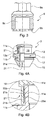
- an antitheft locking device 3 is shown according to a first embodiment of the invention which is made as an antitheft nut and shaped in such a manner to be rotated with difficulty by using a conventional tool.
- the antitheft device 3 comprises a stem 5 in which an externally threaded end 7 is defined, and a head 11 provided with engagement means 13 for a complementary key 9 ( Figure 3 ) by means of which it is possible to rotate said device 3.
- said key 9 comprises a hexagonal axial projection 9a which can be engaged by a fixed key.
- the threaded end 7 of the stem 5 is suitable for engaging a threaded hole, for instance of a motor vehicle wheel hub, in order to lock a corresponding wheel rim.
- the stem 5 is provided with a preferably frusto-conical circumferential abutment portion 15 which extends around the stem 5 at a transition zone 17 between said stem 5 and said head 11.
- the head 11 comprises a first cylindrical portion 11a which is in opposed position with respect to said stem 5, which extends axially and is joint with the stem 5 of the device 3, and a second portion 11b which radially extends around said first portion 11a.
- said engagement means 13 for the complementary key 9 by means of which is possible to rotate said device 3.
- Said engagement means 13 are made, for example, as one or more seats or grooves 13a able for receiving complementary projections 9b provided in the corresponding antitheft key head 9.
- the first cylindrical portion 11a around which said second flange portion 11b of the head 11 radially extends and which is provided with a bushing 19 rotatable in an idle manner, defines a corresponding axial guiding portion for a corresponding axial cavity 9c provided in the key 9.
- the portion 11a comprises stopper means 21 for the bushing 19, which comprise a threaded portion 21a axially extending from a free end or base 11c (upper end in Figure 1B ) of the portion 11a along a portion of the lateral cylindrical outer surface.
- a recessed portion or annular seat 21b is further defined on the lateral outer surface of the portion 11a, is preferably made without threading and axially extends from the portion 21a up to the second abutment portion 11b.
- the bushing 19 comprises a threaded portion 25a which axially extends from the free end 27 (lower end in Figure 4B ) of the bushing 19 along a part of the cylindrical inner surface.
- a recessed portion 25b is defined in the lateral inner surface of the bushing 19, is preferably made without threading and axially extends from the portion 25a along the remaining lateral inner surface of the bushing 19.
- said threaded portions 21a, 25a permit the bushing 19 to be screwed onto the head 11 when assembling the device.
- the radial length of the recessed portion or annular seat 21b is slightly shorter (e.g. some tenths of a millimetre) than the axial length of the threaded portion 25a provided inside the bushing 19 and/or the axial length of the recessed portion or seat 25b is slightly shorter than the axial length of the threaded portion 21a.
- the last part of the threading 21a and/or 25a (typically about half a threading rotation) is deformed and consequently it is impossible to remove the bushing 19 once the threaded portion 25a is arranged inside the seat 21b and, analogously, once the threaded portion 21a is arranged inside the seat 25b.
- the antitheft device 3 is made as an antitheft nut.
- the device 3 according to the invention have been hitherto described with reference to a bolt, it is however possible to manufacture the device as a nut, thus providing the stem 5 without an externally threaded portion, but with an axial hole 31 having a threaded portion 31a to be screwed onto a stem of a threaded stud provided e.g. in the motor vehicle hub.
- the hole 31 it will be possible to make the hole 31 either as a blank-bore or a through-bore.
- an antitheft device is shown, which is made as a bolt wherein the engagement means 13 are however defined in the base 11c of the head 11.
- the bushing 19 is opened at both ends in order to allow the base 11c to be accessible when the device has to be rotated by the complementary key.
- an antitheft device is shown, which is made as a nut wherein the engagement means 13 are defined in the base 11c of the head 11.
- the bushing 19 is therefore opened at both ends in order to allow the base 11c to be accessible when the device has to be rotated by the complementary key.
- the bushing 19 can advantageously be provided with one or more flat surfaces in order to make its rotation easier when it is assembled by screwing.
Landscapes
- Engineering & Computer Science (AREA)
- General Engineering & Computer Science (AREA)
- Mechanical Engineering (AREA)
- Lock And Its Accessories (AREA)
- Burglar Alarm Systems (AREA)
Claims (6)
- Diebstahlsicherungsverschlussvorrichtung (3), insbesondere zur Befestigung eines Rades an der Nabe eines Kraftfahrzeugs, die als eine Mutter oder ein Bolzen ausgelegt ist, umfassend einen Kopf (11), der mit einem Führungsteil (11a) für einen komplementären Schlüssel (9) ausgestattet ist, mittels welchem die genannte Vorrichtung gedreht werden kann, und mit Eingriffsmitteln (13) für den genannten komplementären Schlüssel (9), und einer Buchse (19), die um den genannten Führungsteil (11a) des Kopfes (11) herum frei drehbar gelagert ist, um zu verhindern, dass das genante Führungsteil (11a) durch ein vom entsprechenden Schlüssel (9) unterschiedliches Werkzeug gedreht wird, dadurch gekennzeichnet, dass der genannte Kopf (11) einen mit einem Gewinde versehenen Teil (21 a) und einen Anlageteil (11 b) für die genannte Buchse (19) so umfasst, dass beim Schrauben der genannten Buchse (19) auf den genannten Kopf (11) bis zum genannten Anlageteil (11b) eine Verformung des genannten mit einem Gewinde versehenen Teils (21 a) verursacht wird und dadurch das Abschrauben und das axiale Herausziehen der genannten Buchse (19) vom genannten Kopf (11) vermieden werden.
- Vorrichtung nach Anspruch 1, wobei der genannte Führungsteil (11a) einen mit einem Gewinde versehenen Teil (21 a), der sich axial vom freien Ende (11 c) entlang eines Teils der seitlichen zylinderförmigen äusseren Fläche des Führungsteils (11a) erstreckt, und eine Ausnehmung oder einen ringförmigen Sitz (21 b) aufweist, der an der seitlichen äusseren Fläche des Führungsteils (11a) definiert ist und sich ausgehend vom genannten mit einem Gewinde versehenen Teil (21a) bis zu einem Anlageteil (11b) für die genannte drehbare Buchse (19) axial erstreckt.
- Vorrichtung nach Anspruch 2, wobei die genannte Buchse (19) einen mit einem Gewinde versehenen Teil (25a), der sich vom freien Ende (27) entlang eines Teils der zylinderförmigen inneren Fläche der Buchse (19) axial erstreckt, und eine Ausnehmung (25b) aufweist, die an der seitlichen inneren Fläche der Buchse (19) definiert ist und sich vom mit einem Gewinde versehenen Teil (25a) entlang der verbleibenden seitlichen inneren Fläche der Buchse (19) axial erstreckt.
- Vorrichtung nach Anspruch 3, wobei die genannten mit einem Gewinde versehenen Teile (21 a, 25a) das Schrauben der Buchse (19) auf den Kopf (11) der Vorrichtung bei der Montage der genannten Vorrichtung ermöglichen.
- Vorrichtung nach Anspruch 4, wobei die Ausnehmung oder der ringförmige Sitz (21 b), der an der seitlichen äusseren Fläche des Führungsteils (11a) des Kopfs (11) vorgesehen ist, sich über eine Länge axial erstreckt, die leicht kürzer als die Axiallänge des mit einem Gewinde versehenen Teils (25a) ist, der innerhalb der Buchse (19) angeordnet ist, und/oder die Ausnehmung oder der Sitz (25b), der an der inneren Fläche der Buchse (19) angeordnet ist, sich über eine Länge axial erstreckt, die leicht kürzer als die Axiallänge des mit einem Gewinde versehenen Teils (21 a) ist, der an der äusseren Fläche des Führungsteils (11a) des Kopfs (11) vorgesehen ist, wobei, wenn die Buchse (19) festgeschraubt ist, der letzte Teil des Gewindes (21 a, 25a) verformt ist und die Buchse (19) nicht mehr entfernt werden kann.
- Verfahren zur Herstellung einer Diebstahlsicherungsverschlussvorrichtung (3), insbesondere zur Befestigung eines Rades an der Nabe eines Kraftfahrzeugs, in der Form einer Mutter oder eines Bolzens, umfassend einen Kopf (11), der mit einem Führungsteil (11a) für einen komplementären Schlüssel (9) ausgestattet ist, mittels welchem die genannte Vorrichtung gedreht werden kann, und mit Eingriffsmitteln (13) für den genannten komplementären Schlüssel (9), und einer zugeordneten Buchse (19), die um den genannten Führungsteil (11a) des Kopfes (11) herum frei drehbar ist, um zu verhindern, dass das genante Führungsteil (11a) durch ein vom entsprechenden Schlüssel (9) unterschiedliches Werkzeug gedreht wird, dadurch gekennzeichnet, dass dieses Verfahren einen Schritt des Anschraubens der Buchse (19) auf den Kopf (11) bis zu einem Anlageteil (11 b) für die genannte drehbare Buchse (19) aufweist, um die Verformung des betroffenen Gewindes zu bewerkstelligen, was das Abschrauben der Buchse verhindert.
Applications Claiming Priority (1)
| Application Number | Priority Date | Filing Date | Title |
|---|---|---|---|
| ITTO2009A000178A IT1393210B1 (it) | 2009-03-11 | 2009-03-11 | Dispositivo di bloccaggio antifurto e suo metodo di realizzazione. |
Publications (2)
| Publication Number | Publication Date |
|---|---|
| EP2228176A1 EP2228176A1 (de) | 2010-09-15 |
| EP2228176B1 true EP2228176B1 (de) | 2011-07-13 |
Family
ID=40902830
Family Applications (1)
| Application Number | Title | Priority Date | Filing Date |
|---|---|---|---|
| EP09178610A Not-in-force EP2228176B1 (de) | 2009-03-11 | 2009-12-10 | Diebstahlsicherungsverschlusssystem und Verfahren zu dessen Herstellung |
Country Status (3)
| Country | Link |
|---|---|
| EP (1) | EP2228176B1 (de) |
| AT (1) | ATE516113T1 (de) |
| IT (1) | IT1393210B1 (de) |
Cited By (1)
| Publication number | Priority date | Publication date | Assignee | Title |
|---|---|---|---|---|
| TWI746632B (zh) * | 2016-09-09 | 2021-11-21 | 比利時商赫比工具公司 | 用於取出車輪用安全螺絲的方法、執行該方法的取出器及工具組以及取出器及工具組的用途 |
Families Citing this family (6)
| Publication number | Priority date | Publication date | Assignee | Title |
|---|---|---|---|---|
| US20120103034A1 (en) * | 2010-11-01 | 2012-05-03 | Shartel Mark W | Lock for locking a movable member to fixed member |
| IT1404525B1 (it) * | 2011-02-24 | 2013-11-22 | Groppo | Dispositivo di bloccaggio antifurto e suo metodo di realizzazione. |
| WO2016166575A1 (en) * | 2015-04-16 | 2016-10-20 | Elledi S.R.L. | Antitheft locking device for vehicle wheels |
| IT201600084788A1 (it) * | 2016-08-11 | 2018-02-11 | Matteo Groppo | Elemento di fissaggio per ruote di veicoli |
| CN112922951B (zh) * | 2021-01-18 | 2022-12-06 | 深圳市朗固精密五金有限公司 | 一种防盗螺栓组件 |
| US11788574B2 (en) | 2021-08-13 | 2023-10-17 | Rimgard Sweden AB | Anti-theft locking bolt assembly |
Family Cites Families (2)
| Publication number | Priority date | Publication date | Assignee | Title |
|---|---|---|---|---|
| FR2587422A1 (fr) * | 1985-09-13 | 1987-03-20 | Blimex | Dispositif antivol pour fixer, par vissage, notamment une roue de vehicule |
| US7445414B1 (en) * | 2002-03-01 | 2008-11-04 | Mcgard, Llc | High security fastener constructions |
-
2009
- 2009-03-11 IT ITTO2009A000178A patent/IT1393210B1/it active
- 2009-12-10 AT AT09178610T patent/ATE516113T1/de not_active IP Right Cessation
- 2009-12-10 EP EP09178610A patent/EP2228176B1/de not_active Not-in-force
Cited By (1)
| Publication number | Priority date | Publication date | Assignee | Title |
|---|---|---|---|---|
| TWI746632B (zh) * | 2016-09-09 | 2021-11-21 | 比利時商赫比工具公司 | 用於取出車輪用安全螺絲的方法、執行該方法的取出器及工具組以及取出器及工具組的用途 |
Also Published As
| Publication number | Publication date |
|---|---|
| IT1393210B1 (it) | 2012-04-11 |
| EP2228176A1 (de) | 2010-09-15 |
| ITTO20090178A1 (it) | 2010-09-11 |
| ATE516113T1 (de) | 2011-07-15 |
Similar Documents
| Publication | Publication Date | Title |
|---|---|---|
| EP2228176B1 (de) | Diebstahlsicherungsverschlusssystem und Verfahren zu dessen Herstellung | |
| US11339821B2 (en) | High security fastener with external shroud retainer | |
| US9074617B2 (en) | Security fastener for wheels with a recess hole | |
| EP1157217B1 (de) | Schraubeinrichtung und diebstahlsicherungsanordnung für fahrzeugräder und kraftfahrzeug mit einer solchen diebstahlsicherungsanordnung | |
| US10738819B2 (en) | High security fastener | |
| EP2196686B1 (de) | Diebstahlsicherung zum Fixieren eines Rades an einer Motorfahrzeugnabe | |
| US10816023B2 (en) | Tamper-resistant fastener for connecting a wheel rim to a hub flange of a motor vehicle | |
| WO2017020870A1 (zh) | 一种车轮 | |
| EP2816244B1 (de) | Anti-Diebstahl-Verriegelungsvorrichtung für Fahrzeugräder | |
| EP3056748B1 (de) | Als mutter oder schraube hergestellte verriegelungsvorrichtung | |
| EP3283304B1 (de) | Diebstahlsicherungsvorrichtung für fahrzeugräder | |
| EP4402388B1 (de) | Hochsicheres befestigungselement mit antriebskupplungsschlüssel | |
| US10899175B2 (en) | Wheel lock key assembly and wheel lock key retention mechanism | |
| WO2020117696A1 (en) | Coil shroud high security fastener | |
| WO2001009527A1 (en) | Anti-theft device | |
| CN110594275B (zh) | 用于车轮紧固件的护套组件 | |
| WO2004001237A1 (en) | Screw-threaded fastening | |
| IT202300004158U1 (it) | Dispositivo di bloccaggio antifurto perfezionato per ruota di veicolo | |
| IT202300021171A1 (it) | Dispositivo di bloccaggio antifurto perfezionato per ruota di veicolo | |
| HK1074238A1 (en) | Anti-theft device intended, in particular, for vehicle wheels |
Legal Events
| Date | Code | Title | Description |
|---|---|---|---|
| PUAI | Public reference made under article 153(3) epc to a published international application that has entered the european phase |
Free format text: ORIGINAL CODE: 0009012 |
|
| AK | Designated contracting states |
Kind code of ref document: A1 Designated state(s): AT BE BG CH CY CZ DE DK EE ES FI FR GB GR HR HU IE IS IT LI LT LU LV MC MK MT NL NO PL PT RO SE SI SK SM TR |
|
| AX | Request for extension of the european patent |
Extension state: AL BA RS |
|
| 17P | Request for examination filed |
Effective date: 20100903 |
|
| 17Q | First examination report despatched |
Effective date: 20100924 |
|
| GRAP | Despatch of communication of intention to grant a patent |
Free format text: ORIGINAL CODE: EPIDOSNIGR1 |
|
| RIC1 | Information provided on ipc code assigned before grant |
Ipc: B25B 13/48 20060101AFI20110110BHEP Ipc: B60B 3/16 20060101ALI20110110BHEP Ipc: F16B 23/00 20060101ALI20110110BHEP Ipc: F16B 37/14 20060101ALI20110110BHEP Ipc: F16B 41/00 20060101ALI20110110BHEP |
|
| GRAS | Grant fee paid |
Free format text: ORIGINAL CODE: EPIDOSNIGR3 |
|
| GRAA | (expected) grant |
Free format text: ORIGINAL CODE: 0009210 |
|
| AK | Designated contracting states |
Kind code of ref document: B1 Designated state(s): AT BE BG CH CY CZ DE DK EE ES FI FR GB GR HR HU IE IS IT LI LT LU LV MC MK MT NL NO PL PT RO SE SI SK SM TR |
|
| REG | Reference to a national code |
Ref country code: GB Ref legal event code: FG4D |
|
| REG | Reference to a national code |
Ref country code: CH Ref legal event code: EP |
|
| REG | Reference to a national code |
Ref country code: IE Ref legal event code: FG4D |
|
| REG | Reference to a national code |
Ref country code: DE Ref legal event code: R096 Ref document number: 602009001797 Country of ref document: DE Effective date: 20110901 |
|
| REG | Reference to a national code |
Ref country code: SE Ref legal event code: TRGR |
|
| REG | Reference to a national code |
Ref country code: NL Ref legal event code: VDEP Effective date: 20110713 |
|
| REG | Reference to a national code |
Ref country code: AT Ref legal event code: MK05 Ref document number: 516113 Country of ref document: AT Kind code of ref document: T Effective date: 20110713 |
|
| PG25 | Lapsed in a contracting state [announced via postgrant information from national office to epo] |
Ref country code: PT Free format text: LAPSE BECAUSE OF FAILURE TO SUBMIT A TRANSLATION OF THE DESCRIPTION OR TO PAY THE FEE WITHIN THE PRESCRIBED TIME-LIMIT Effective date: 20111114 Ref country code: LT Free format text: LAPSE BECAUSE OF FAILURE TO SUBMIT A TRANSLATION OF THE DESCRIPTION OR TO PAY THE FEE WITHIN THE PRESCRIBED TIME-LIMIT Effective date: 20110713 Ref country code: NO Free format text: LAPSE BECAUSE OF FAILURE TO SUBMIT A TRANSLATION OF THE DESCRIPTION OR TO PAY THE FEE WITHIN THE PRESCRIBED TIME-LIMIT Effective date: 20111013 Ref country code: HR Free format text: LAPSE BECAUSE OF FAILURE TO SUBMIT A TRANSLATION OF THE DESCRIPTION OR TO PAY THE FEE WITHIN THE PRESCRIBED TIME-LIMIT Effective date: 20110713 Ref country code: BE Free format text: LAPSE BECAUSE OF FAILURE TO SUBMIT A TRANSLATION OF THE DESCRIPTION OR TO PAY THE FEE WITHIN THE PRESCRIBED TIME-LIMIT Effective date: 20110713 Ref country code: NL Free format text: LAPSE BECAUSE OF FAILURE TO SUBMIT A TRANSLATION OF THE DESCRIPTION OR TO PAY THE FEE WITHIN THE PRESCRIBED TIME-LIMIT Effective date: 20110713 Ref country code: IS Free format text: LAPSE BECAUSE OF FAILURE TO SUBMIT A TRANSLATION OF THE DESCRIPTION OR TO PAY THE FEE WITHIN THE PRESCRIBED TIME-LIMIT Effective date: 20111113 Ref country code: FI Free format text: LAPSE BECAUSE OF FAILURE TO SUBMIT A TRANSLATION OF THE DESCRIPTION OR TO PAY THE FEE WITHIN THE PRESCRIBED TIME-LIMIT Effective date: 20110713 |
|
| PG25 | Lapsed in a contracting state [announced via postgrant information from national office to epo] |
Ref country code: LV Free format text: LAPSE BECAUSE OF FAILURE TO SUBMIT A TRANSLATION OF THE DESCRIPTION OR TO PAY THE FEE WITHIN THE PRESCRIBED TIME-LIMIT Effective date: 20110713 Ref country code: GR Free format text: LAPSE BECAUSE OF FAILURE TO SUBMIT A TRANSLATION OF THE DESCRIPTION OR TO PAY THE FEE WITHIN THE PRESCRIBED TIME-LIMIT Effective date: 20111014 Ref country code: PL Free format text: LAPSE BECAUSE OF FAILURE TO SUBMIT A TRANSLATION OF THE DESCRIPTION OR TO PAY THE FEE WITHIN THE PRESCRIBED TIME-LIMIT Effective date: 20110713 Ref country code: SI Free format text: LAPSE BECAUSE OF FAILURE TO SUBMIT A TRANSLATION OF THE DESCRIPTION OR TO PAY THE FEE WITHIN THE PRESCRIBED TIME-LIMIT Effective date: 20110713 Ref country code: CY Free format text: LAPSE BECAUSE OF FAILURE TO SUBMIT A TRANSLATION OF THE DESCRIPTION OR TO PAY THE FEE WITHIN THE PRESCRIBED TIME-LIMIT Effective date: 20110713 Ref country code: AT Free format text: LAPSE BECAUSE OF FAILURE TO SUBMIT A TRANSLATION OF THE DESCRIPTION OR TO PAY THE FEE WITHIN THE PRESCRIBED TIME-LIMIT Effective date: 20110713 |
|
| PG25 | Lapsed in a contracting state [announced via postgrant information from national office to epo] |
Ref country code: CZ Free format text: LAPSE BECAUSE OF FAILURE TO SUBMIT A TRANSLATION OF THE DESCRIPTION OR TO PAY THE FEE WITHIN THE PRESCRIBED TIME-LIMIT Effective date: 20110713 Ref country code: SK Free format text: LAPSE BECAUSE OF FAILURE TO SUBMIT A TRANSLATION OF THE DESCRIPTION OR TO PAY THE FEE WITHIN THE PRESCRIBED TIME-LIMIT Effective date: 20110713 |
|
| PLBE | No opposition filed within time limit |
Free format text: ORIGINAL CODE: 0009261 |
|
| STAA | Information on the status of an ep patent application or granted ep patent |
Free format text: STATUS: NO OPPOSITION FILED WITHIN TIME LIMIT |
|
| PG25 | Lapsed in a contracting state [announced via postgrant information from national office to epo] |
Ref country code: EE Free format text: LAPSE BECAUSE OF FAILURE TO SUBMIT A TRANSLATION OF THE DESCRIPTION OR TO PAY THE FEE WITHIN THE PRESCRIBED TIME-LIMIT Effective date: 20110713 Ref country code: RO Free format text: LAPSE BECAUSE OF FAILURE TO SUBMIT A TRANSLATION OF THE DESCRIPTION OR TO PAY THE FEE WITHIN THE PRESCRIBED TIME-LIMIT Effective date: 20110713 |
|
| 26N | No opposition filed |
Effective date: 20120416 |
|
| PG25 | Lapsed in a contracting state [announced via postgrant information from national office to epo] |
Ref country code: DK Free format text: LAPSE BECAUSE OF FAILURE TO SUBMIT A TRANSLATION OF THE DESCRIPTION OR TO PAY THE FEE WITHIN THE PRESCRIBED TIME-LIMIT Effective date: 20110713 |
|
| PG25 | Lapsed in a contracting state [announced via postgrant information from national office to epo] |
Ref country code: MC Free format text: LAPSE BECAUSE OF NON-PAYMENT OF DUE FEES Effective date: 20111231 |
|
| REG | Reference to a national code |
Ref country code: DE Ref legal event code: R097 Ref document number: 602009001797 Country of ref document: DE Effective date: 20120416 |
|
| REG | Reference to a national code |
Ref country code: FR Ref legal event code: ST Effective date: 20120831 |
|
| REG | Reference to a national code |
Ref country code: IE Ref legal event code: MM4A |
|
| PG25 | Lapsed in a contracting state [announced via postgrant information from national office to epo] |
Ref country code: IE Free format text: LAPSE BECAUSE OF NON-PAYMENT OF DUE FEES Effective date: 20111210 |
|
| PG25 | Lapsed in a contracting state [announced via postgrant information from national office to epo] |
Ref country code: MK Free format text: LAPSE BECAUSE OF FAILURE TO SUBMIT A TRANSLATION OF THE DESCRIPTION OR TO PAY THE FEE WITHIN THE PRESCRIBED TIME-LIMIT Effective date: 20110713 Ref country code: MT Free format text: LAPSE BECAUSE OF FAILURE TO SUBMIT A TRANSLATION OF THE DESCRIPTION OR TO PAY THE FEE WITHIN THE PRESCRIBED TIME-LIMIT Effective date: 20110713 |
|
| PG25 | Lapsed in a contracting state [announced via postgrant information from national office to epo] |
Ref country code: SM Free format text: LAPSE BECAUSE OF FAILURE TO SUBMIT A TRANSLATION OF THE DESCRIPTION OR TO PAY THE FEE WITHIN THE PRESCRIBED TIME-LIMIT Effective date: 20110713 Ref country code: ES Free format text: LAPSE BECAUSE OF FAILURE TO SUBMIT A TRANSLATION OF THE DESCRIPTION OR TO PAY THE FEE WITHIN THE PRESCRIBED TIME-LIMIT Effective date: 20111024 Ref country code: FR Free format text: LAPSE BECAUSE OF NON-PAYMENT OF DUE FEES Effective date: 20120102 |
|
| PG25 | Lapsed in a contracting state [announced via postgrant information from national office to epo] |
Ref country code: LU Free format text: LAPSE BECAUSE OF NON-PAYMENT OF DUE FEES Effective date: 20111210 |
|
| PG25 | Lapsed in a contracting state [announced via postgrant information from national office to epo] |
Ref country code: BG Free format text: LAPSE BECAUSE OF FAILURE TO SUBMIT A TRANSLATION OF THE DESCRIPTION OR TO PAY THE FEE WITHIN THE PRESCRIBED TIME-LIMIT Effective date: 20111013 |
|
| PG25 | Lapsed in a contracting state [announced via postgrant information from national office to epo] |
Ref country code: TR Free format text: LAPSE BECAUSE OF FAILURE TO SUBMIT A TRANSLATION OF THE DESCRIPTION OR TO PAY THE FEE WITHIN THE PRESCRIBED TIME-LIMIT Effective date: 20110713 |
|
| PG25 | Lapsed in a contracting state [announced via postgrant information from national office to epo] |
Ref country code: HU Free format text: LAPSE BECAUSE OF FAILURE TO SUBMIT A TRANSLATION OF THE DESCRIPTION OR TO PAY THE FEE WITHIN THE PRESCRIBED TIME-LIMIT Effective date: 20110713 |
|
| REG | Reference to a national code |
Ref country code: CH Ref legal event code: PL |
|
| PG25 | Lapsed in a contracting state [announced via postgrant information from national office to epo] |
Ref country code: LI Free format text: LAPSE BECAUSE OF NON-PAYMENT OF DUE FEES Effective date: 20131231 Ref country code: CH Free format text: LAPSE BECAUSE OF NON-PAYMENT OF DUE FEES Effective date: 20131231 |
|
| PGFP | Annual fee paid to national office [announced via postgrant information from national office to epo] |
Ref country code: GB Payment date: 20151217 Year of fee payment: 7 Ref country code: DE Payment date: 20151030 Year of fee payment: 7 Ref country code: IT Payment date: 20151029 Year of fee payment: 7 |
|
| PGFP | Annual fee paid to national office [announced via postgrant information from national office to epo] |
Ref country code: SE Payment date: 20151217 Year of fee payment: 7 |
|
| REG | Reference to a national code |
Ref country code: DE Ref legal event code: R119 Ref document number: 602009001797 Country of ref document: DE |
|
| REG | Reference to a national code |
Ref country code: SE Ref legal event code: EUG |
|
| GBPC | Gb: european patent ceased through non-payment of renewal fee |
Effective date: 20161210 |
|
| PG25 | Lapsed in a contracting state [announced via postgrant information from national office to epo] |
Ref country code: SE Free format text: LAPSE BECAUSE OF NON-PAYMENT OF DUE FEES Effective date: 20161211 |
|
| PG25 | Lapsed in a contracting state [announced via postgrant information from national office to epo] |
Ref country code: IT Free format text: LAPSE BECAUSE OF NON-PAYMENT OF DUE FEES Effective date: 20161210 |
|
| PG25 | Lapsed in a contracting state [announced via postgrant information from national office to epo] |
Ref country code: DE Free format text: LAPSE BECAUSE OF NON-PAYMENT OF DUE FEES Effective date: 20170701 Ref country code: GB Free format text: LAPSE BECAUSE OF NON-PAYMENT OF DUE FEES Effective date: 20161210 |