EP2227648B1 - Rohrstück und verfahren zur herstellung einer rohrleitung daraus - Google Patents
Rohrstück und verfahren zur herstellung einer rohrleitung daraus Download PDFInfo
- Publication number
- EP2227648B1 EP2227648B1 EP08855632.9A EP08855632A EP2227648B1 EP 2227648 B1 EP2227648 B1 EP 2227648B1 EP 08855632 A EP08855632 A EP 08855632A EP 2227648 B1 EP2227648 B1 EP 2227648B1
- Authority
- EP
- European Patent Office
- Prior art keywords
- pipe
- stalk
- abutments
- pipeline
- axial movement
- Prior art date
- Legal status (The legal status is an assumption and is not a legal conclusion. Google has not performed a legal analysis and makes no representation as to the accuracy of the status listed.)
- Not-in-force
Links
- 238000000034 method Methods 0.000 title claims description 22
- 238000003466 welding Methods 0.000 claims description 17
- 239000011810 insulating material Substances 0.000 claims description 2
- 238000009413 insulation Methods 0.000 claims description 2
- 238000005304 joining Methods 0.000 description 7
- 238000009434 installation Methods 0.000 description 6
- 239000010779 crude oil Substances 0.000 description 4
- 239000012530 fluid Substances 0.000 description 4
- 239000012774 insulation material Substances 0.000 description 3
- 238000005452 bending Methods 0.000 description 2
- 230000000295 complement effect Effects 0.000 description 2
- MWRWFPQBGSZWNV-UHFFFAOYSA-N Dinitrosopentamethylenetetramine Chemical compound C1N2CN(N=O)CN1CN(N=O)C2 MWRWFPQBGSZWNV-UHFFFAOYSA-N 0.000 description 1
- 229940112112 capex Drugs 0.000 description 1
- 238000005520 cutting process Methods 0.000 description 1
- 230000007423 decrease Effects 0.000 description 1
- FEBLZLNTKCEFIT-VSXGLTOVSA-N fluocinolone acetonide Chemical compound C1([C@@H](F)C2)=CC(=O)C=C[C@]1(C)[C@]1(F)[C@@H]2[C@@H]2C[C@H]3OC(C)(C)O[C@@]3(C(=O)CO)[C@@]2(C)C[C@@H]1O FEBLZLNTKCEFIT-VSXGLTOVSA-N 0.000 description 1
- 238000003780 insertion Methods 0.000 description 1
- 230000037431 insertion Effects 0.000 description 1
- 239000012263 liquid product Substances 0.000 description 1
- 238000012986 modification Methods 0.000 description 1
- 230000004048 modification Effects 0.000 description 1
- 239000003921 oil Substances 0.000 description 1
- 230000000717 retained effect Effects 0.000 description 1
- 238000003860 storage Methods 0.000 description 1
- XLYOFNOQVPJJNP-UHFFFAOYSA-N water Substances O XLYOFNOQVPJJNP-UHFFFAOYSA-N 0.000 description 1
Images



Classifications
-
- F—MECHANICAL ENGINEERING; LIGHTING; HEATING; WEAPONS; BLASTING
- F16—ENGINEERING ELEMENTS AND UNITS; GENERAL MEASURES FOR PRODUCING AND MAINTAINING EFFECTIVE FUNCTIONING OF MACHINES OR INSTALLATIONS; THERMAL INSULATION IN GENERAL
- F16L—PIPES; JOINTS OR FITTINGS FOR PIPES; SUPPORTS FOR PIPES, CABLES OR PROTECTIVE TUBING; MEANS FOR THERMAL INSULATION IN GENERAL
- F16L1/00—Laying or reclaiming pipes; Repairing or joining pipes on or under water
- F16L1/12—Laying or reclaiming pipes on or under water
- F16L1/16—Laying or reclaiming pipes on or under water on the bottom
- F16L1/18—Laying or reclaiming pipes on or under water on the bottom the pipes being S- or J-shaped and under tension during laying
-
- F—MECHANICAL ENGINEERING; LIGHTING; HEATING; WEAPONS; BLASTING
- F16—ENGINEERING ELEMENTS AND UNITS; GENERAL MEASURES FOR PRODUCING AND MAINTAINING EFFECTIVE FUNCTIONING OF MACHINES OR INSTALLATIONS; THERMAL INSULATION IN GENERAL
- F16L—PIPES; JOINTS OR FITTINGS FOR PIPES; SUPPORTS FOR PIPES, CABLES OR PROTECTIVE TUBING; MEANS FOR THERMAL INSULATION IN GENERAL
- F16L1/00—Laying or reclaiming pipes; Repairing or joining pipes on or under water
- F16L1/12—Laying or reclaiming pipes on or under water
- F16L1/16—Laying or reclaiming pipes on or under water on the bottom
- F16L1/161—Laying or reclaiming pipes on or under water on the bottom the pipe being composed of sections of short length
-
- F—MECHANICAL ENGINEERING; LIGHTING; HEATING; WEAPONS; BLASTING
- F16—ENGINEERING ELEMENTS AND UNITS; GENERAL MEASURES FOR PRODUCING AND MAINTAINING EFFECTIVE FUNCTIONING OF MACHINES OR INSTALLATIONS; THERMAL INSULATION IN GENERAL
- F16L—PIPES; JOINTS OR FITTINGS FOR PIPES; SUPPORTS FOR PIPES, CABLES OR PROTECTIVE TUBING; MEANS FOR THERMAL INSULATION IN GENERAL
- F16L13/00—Non-disconnectable pipe joints, e.g. soldered, adhesive, or caulked joints
- F16L13/02—Welded joints
- F16L13/0254—Welded joints the pipes having an internal or external coating
-
- F—MECHANICAL ENGINEERING; LIGHTING; HEATING; WEAPONS; BLASTING
- F16—ENGINEERING ELEMENTS AND UNITS; GENERAL MEASURES FOR PRODUCING AND MAINTAINING EFFECTIVE FUNCTIONING OF MACHINES OR INSTALLATIONS; THERMAL INSULATION IN GENERAL
- F16L—PIPES; JOINTS OR FITTINGS FOR PIPES; SUPPORTS FOR PIPES, CABLES OR PROTECTIVE TUBING; MEANS FOR THERMAL INSULATION IN GENERAL
- F16L39/00—Joints or fittings for double-walled or multi-channel pipes or pipe assemblies
- F16L39/005—Joints or fittings for double-walled or multi-channel pipes or pipe assemblies for concentric pipes
-
- F—MECHANICAL ENGINEERING; LIGHTING; HEATING; WEAPONS; BLASTING
- F16—ENGINEERING ELEMENTS AND UNITS; GENERAL MEASURES FOR PRODUCING AND MAINTAINING EFFECTIVE FUNCTIONING OF MACHINES OR INSTALLATIONS; THERMAL INSULATION IN GENERAL
- F16L—PIPES; JOINTS OR FITTINGS FOR PIPES; SUPPORTS FOR PIPES, CABLES OR PROTECTIVE TUBING; MEANS FOR THERMAL INSULATION IN GENERAL
- F16L39/00—Joints or fittings for double-walled or multi-channel pipes or pipe assemblies
- F16L39/04—Joints or fittings for double-walled or multi-channel pipes or pipe assemblies allowing adjustment or movement
-
- F—MECHANICAL ENGINEERING; LIGHTING; HEATING; WEAPONS; BLASTING
- F16—ENGINEERING ELEMENTS AND UNITS; GENERAL MEASURES FOR PRODUCING AND MAINTAINING EFFECTIVE FUNCTIONING OF MACHINES OR INSTALLATIONS; THERMAL INSULATION IN GENERAL
- F16L—PIPES; JOINTS OR FITTINGS FOR PIPES; SUPPORTS FOR PIPES, CABLES OR PROTECTIVE TUBING; MEANS FOR THERMAL INSULATION IN GENERAL
- F16L59/00—Thermal insulation in general
- F16L59/14—Arrangements for the insulation of pipes or pipe systems
- F16L59/16—Arrangements specially adapted to local requirements at flanges, junctions, valves or the like
- F16L59/18—Arrangements specially adapted to local requirements at flanges, junctions, valves or the like adapted for joints
- F16L59/20—Arrangements specially adapted to local requirements at flanges, junctions, valves or the like adapted for joints for non-disconnectable joints
-
- F—MECHANICAL ENGINEERING; LIGHTING; HEATING; WEAPONS; BLASTING
- F16—ENGINEERING ELEMENTS AND UNITS; GENERAL MEASURES FOR PRODUCING AND MAINTAINING EFFECTIVE FUNCTIONING OF MACHINES OR INSTALLATIONS; THERMAL INSULATION IN GENERAL
- F16L—PIPES; JOINTS OR FITTINGS FOR PIPES; SUPPORTS FOR PIPES, CABLES OR PROTECTIVE TUBING; MEANS FOR THERMAL INSULATION IN GENERAL
- F16L9/00—Rigid pipes
- F16L9/18—Double-walled pipes; Multi-channel pipes or pipe assemblies
-
- Y—GENERAL TAGGING OF NEW TECHNOLOGICAL DEVELOPMENTS; GENERAL TAGGING OF CROSS-SECTIONAL TECHNOLOGIES SPANNING OVER SEVERAL SECTIONS OF THE IPC; TECHNICAL SUBJECTS COVERED BY FORMER USPC CROSS-REFERENCE ART COLLECTIONS [XRACs] AND DIGESTS
- Y10—TECHNICAL SUBJECTS COVERED BY FORMER USPC
- Y10T—TECHNICAL SUBJECTS COVERED BY FORMER US CLASSIFICATION
- Y10T137/00—Fluid handling
- Y10T137/0318—Processes
- Y10T137/0402—Cleaning, repairing, or assembling
Definitions
- the present invention relates to pipe stalk and a method for assembling a pipe-in-pipe pipeline from a plurality of such pipe stalks, and in particular to method and apparatus for assembling a pipe-in-pipe pipeline directly on a pipe take-off assembly of a pipe laying vessel.
- Marine pipelines for conveying gas or crude oil are typically laid from specialised pipelaying vessels or barges, whereby pipelines are deployed and lowered to the seabed in a controlled fashion, the pipelines either being assembled from individual pipe sections on the vessel (referred to as “stovepiping”) or spooled from one or more reels mounted on the vessel (referred to as “reel pipelaying”).
- the stovepiping method generally requires the pipelaying operation to be periodically halted to permit additional pipe sections to be welded to the pipeline and also requires many experienced welders and additional welding equipment to be carried on the vessel, working in difficult conditions. Therefore stovepiping is a relatively slow and difficult process.
- reel pipelaying wherein the pipeline can be prefabricated onshore and spooled onto a large reel, reduces the labour requirements onboard the vessel and considerably speeds up the pipelaying operation.
- a requirement of the reel pipelaying method is to provide means for straightening and guiding the pipeline as it leaves the reel, typically by means of series of rollers or tracks that impart sufficient reverse bending force to residual curvature from the pipeline and guides the pipeline into the water at an angle optimised to reduce bending stresses.
- the outer pipes of a pipe-in-pipe flowline are joined together using two half shells required to bridge the gap between the ends of the outer pipes.
- This requires cutting of the pipe ends to ensure sufficient room for the half shells and several welding processes for joining the half shells to the ends of the adjacent outer pipes and to each other, leading to longer installation times and a greater risk of leakage.
- it is necessary to store the half shells on the installation vessel along with the pipe stalks, requiring greater storage space on the vessel and limiting the amount of pipe that can be laid.
- US 1872089 describes an expansion joint for use in a line conveying steam or other hot fluid, to provide the inner slide member of an expansion joint with a cylindrical guide, spaced well inwardly from the outer shell and internally fitting and secured to the outer shell.
- the present invention saves CAPEX and OPEX by reducing the time taken to join the ends of adjacent pipes and reducing the total number of welds required, and by avoiding the need for the use of half shells.
- the retaining assembly comprises two or more components able to engage in at least the first configuration for preventing axial movement, and generally able not to engage or to disengage in the second configuration for allowing axial movement between the outer pipe and the inner pipe.
- Suitable components include one or more shoulders, pins, studs, plates and other projecting pieces, units or devices, optionally moveable with respect to the inner pipe(s), outer pipe or both.
- the retaining assembly preferably comprises at least one component on an inner pipe, and at least one complementary and/or corresponding component on the outer pipe, optionally with one or more components thereinbetween.
- the retaining assembly comprises non-joining components, that is components which are not required to be secured or fixed or attached to each other in either the first configuration or the second configuration.
- non-conjoining minimises and/or avoids actions required to provide the retaining assembly in its first configuration, second configuration or both.
- the retaining assembly is at or near one end of the pipe stalk.
- Pipe stalks are typically elongate, more typically several or many metres long.
- the present invention is particularly advantageous by locating the retaining assembly at or near one end of the pipe stalk, so as to minimise interference in or along the remainder of the pipe stalk, generally comprising the majority of the length of the pipe stalk.
- the pipe stalk of the present invention is intended to be the repeated item or section to create a pipeline for conveying a fluid flow such as gas or crude oil.
- the welding of one pipe stalk to another pipe stalk is generally carried out vertically, or at least based on wholly or substantially vertical positioning and alignment of the pipe stalks.
- One pipe stalk can be held in a generally vertical position by a suitable clamp, such as a hang-off clamp, which pipe stalk may be the end section of a formed or forming pipeline.
- a second pipe stalk can be held or supported by one or more other suitable clamps, able to be aligned above the top of the held pipe stalk so as to weld such pipe stalks together.
- the welding of adjacent pipe stalks comprises at least the welding of the inner pipe of a first pipe stalk and the inner pipe of a second pipe stalk, generally after the alignment of the inner pipe of the first pipe stalk in a downward direction towards the top of the inner pipe of another pipe stalk, generally being the pipe stalk held in a vertical position by a hang off clamp.
- the retaining assembly is moveable between its first configuration and its second configuration after welding of the inner pipes of adjacent pipe stalks together.
- the retaining assembly is moveable between its first configuration and its second configuration after welding of the inner pipes of adjacent pipe stalks together.
- two adjacent pipe stalks are welded together, generally comprising the welding of at least one inner pipe and the outer pipe, relative movement of the retaining assembly of each pipe stalk may or may not be required or necessary.
- the first and second abutments may have any suitable shape, size and design, and may or may not be the same or similar, and/or corresponding and/or complementary. It is only that the first and second abutments can at least abut with the key member(s) in the first configuration of the retaining assembly.
- first and second abutments each extend between the inner and outer pipelines over a segment of said annular space between said inner and outer pipes of said pipe stalk.
- the sum of the circumferential lengths of the first and second abutments may be substantially equal to the circumference of said annular space.
- Said at least one key member may comprise a segment of a ring having an inner diameter substantially equal to the outer diameter of the inner pipe and an outer diameter substantially equal to the inner diameter of the outer pipe.
- the outer pipe may be provided with a pair of first abutment provided on the inner surface of the outer pipe at diametrically opposed locations thereon, said inner pipe being provided with a pair of second abutment provided on the outer surface of the inner pipe at diametrically opposed locations thereon, said first abutment being spaced approximately 90° from said second abutment in a circumferential direction, a pair of key members being provided to be insertable between the first and second abutments.
- At least one holding means may be provided for selectively retaining the inner pipe with respect to the outer pipe when the pipe stalk is held in a clamp means by said outer pipe in a position wherein said inner pipe extends axially below the lower end of said outer pipe with said first abutment positioned axially above said second abutment to allow the inner pipe to be welded to the upper end of an inner pipe of a pipeline.
- Said holding means preferably comprises an elongate member having a first end adapted to engage an upper end of the outer pipe and a second end adapted to be connectable to said second abutment. The second end may be threaded to be received in a corresponding threaded aperture in the second abutment. The first end of said elongate member may be connectable to upper edge of the outer pipe, for example, by means of a hook shaped end provided thereon.
- a thermal insulation media is provided in the annular space between inner and outer pipes of the pipe stalk.
- a pipeline when formed from a plurality of pipe stalks according to the first aspect of the present invention.
- the step of inserting said at least one first or said at least one further key member comprises axially inserting the key member into said annular space past the second abutment to abut said first abutment and subsequently rotating said at least one key member to extend between said first and second abutments.
- the method may comprise the further step of holding the outer pipe of said further pipe in a raised position with respect to said inner pipe of said further pipe during step (iii).
- the step of holding the outer pipe with respect to the inner pipe of said further pipe may comprise attaching an elongate holding means to said further pipe, said holding means having a first end that is attached to said second abutments provided on said inner pipe and a hook shaped second end that is hooked over an upper edge of the outer pipe.
- the method may comprise the further step of applying a thermally insulating media around exposed sections of inner pipes of the first and further pipe stalks following the welding operation of step (iii).
- the present invention provides a method and apparatus of forming a pipe-in-pipe pipeline from a plurality of pipe stalks that enables the inner and outer pipes of each pipe stalk to be welded to the pipeline on the pipe take-off assembly of a pipe laying vessel, greatly facilitating and speeding up the pipe laying and assembly operation.
- a pipe-in-pipe pipeline is formed from a plurality of individual pipe stalks or sections 2, each comprising an outer pipe 4 and a concentrically arranged inner pipe 6, an insulation material 8 being provided in the annular space between the inner and outer pipes to thermally insulate the pipeline.
- the inner pipe 6 defines a flowline for carrying a fluid, such as crude oil or gas.
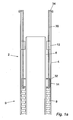
- Figure 1 shows a typical pipe stalk labelled "B” as an embodiment of the present invention, and the top of a pipe-in-pipe pipeline labelled "A", being the upper or top part or section of another pipe stalk, held in a hang off clamp 20.
- Figure 1a is an enlarged sectional view through just the uppermost part of the pipe stalk B of Figure 1
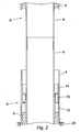
- Figure 2 shows the step of joining the bottom of the inner pipe 6 of the pipe stalk B to the top of the inner pipe 6 of the pipeline A once the pipe stalk B has been lowered to meet the pipeline A as described further below.
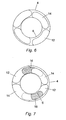
- each pipe stalk 2 is provided with a pair of diametrically opposed first abutments 12 extending from the inner surface thereof adjacent an upper end of the pipes 4, each first abutment 12 extending approximately 90° around the circumference of the annular space between the inner and outer pipes 6, 4, as best seen from Fig. 6 .
- each pipe stalk 2 is provided with a part of diametrically opposed second abutments 14 extending radially from the outer surface thereof adjacent an upper end of the inner pipe 6, each second abutment 14 extending radially approximately 90° around the circumference of the annular space between the inner and outer pipes 6, 4, the second abutments 14 being circumferentially offset from the first abutments 12 by 90° such that the first abutments 12 can move past and between the second abutments 14 during axial movement of the outer pipe 4 with respect to the inner pipe 6.
- a pair of key members 16 are inserted between the first and second abutments 12, 14, as shown in Fig. 2 , to block axial movement of the second abutments 14 past the first abutments 12, as will be described below in more detail.
- the key members may be helix shaped in order to facilitate their insertion into the annular space between the first and second abutment.
- the pipeline A is retained on the hang off clamp (HOC) 20 of the pipelaying vessel.
- HOC hang off clamp
- Key members 16 are located in the space between the first and second abutments of at least the uppermost pipe stalk or section of the pipeline A.
- the pipe stalk B is lowered into position above the pipeline A until the inner pipe 6 of the pipe stalk B abuts against the inner pipe 6 of the pipeline A, whereby said inner pipes 6 can be welded together.
- the pipe stalk B can be held in a running tensioner (not shown) which clamps the outer pipe 4 of the pipe stalk B.
- Elongate retaining rods 30 have been inserted into the annular space between the inner and outer pipes 6, 4 of the pipe stalk B.
- the retaining rods 30 are attached to the second abutments 14 of the inner pipe 6, for example by screwing a threaded end 32 of each retaining rod 30 into a correspondingly threaded receiving aperture in the respective second abutments 14.
- the upper ends 34 of the retaining rods 30 are hook shaped to be received over an upper edge of the outer pipe 4 wherein the inner pipe 6 of the pipe stalk B is effectively hung from the outer pipe 4.
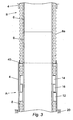
- insulation material 8a is placed over the exposed ends of the joined inner pipes 6 of the pipeline A and the pipe stalk B, and the outer pipe 4 of the pipe stalk B is lowered until it abuts the outer pipe 4 of the pipeline A.
- the abutting outer pipes 4 are now welded together, as shown in Fig. 4 .
- a heat shield 40 may be inserted beneath the junction of the adjacent outer pipes 4 to protect the insulation material 8a from the heat of the welding operation.
- the installation of the key members 16 is shown in Figure 5 , and is achieved by first axially inserting the key members 16 into the annular space between the inner and outer pipes 4, 6 until the key members 16 rest on the upper surface of the first abutments 12, the key members 16 moving axially past the second abutments 14 during such process.
- the key members 16 are slid sideways in a circumferential direction to partially extend beneath the second abutments 14 as shown in Figure 7 , such that a first portion of each key member 16 is in contact with the upper face of a respective first abutment member 12 and a second portion of each key member 16 is in contact with a lower face of a respective second abutment member 14, the key members 16 thereby preventing axial movement of the second abutments 14 towards the first abutments 12 and thereby supporting the inner pipe 6 within the outer pipe 4.
Landscapes
- Engineering & Computer Science (AREA)
- General Engineering & Computer Science (AREA)
- Mechanical Engineering (AREA)
- Supports For Pipes And Cables (AREA)
- Thermal Insulation (AREA)
Claims (19)
- Ein Rohrstück (2) für eine Rohr-in-Rohr-Rohrleitung, wobei das Rohrstück ein äußeres Rohr (4) und mindestens ein inneres Rohr (6), das sich innerhalb des äußeren Rohrs befindet, beinhaltet und eine Rückhalteanordnung aufweist, die beweglich ist wischen:einer ersten Konfiguration zum Verhindern einer axialen Belegung des inneren Rohrs in Bezug auf das äußere Rohr in einer Abwärtsrichtung, wenn das äußere Rohr während des Schweißens des inneren Rohrs an ein inneres Rohr eines benachbarten Rohrstücks vertikal gehalten wird; undeiner zweiten Konfiguration zum Ermöglichen einer axialen Belegung des äußeren Rohrs in Bezug auf das innere Rohr nach dem Verschweißen der inneren Rohre;wobei die Rückhalteanordnung mindestens zwei umfangsmäßig beabstandete erste Stoßelemente (12), die auf einer inneren Oberfläche des äußeren Rohrs bereitgestellt sind, mindestens zwei umfangsmäßig zweite Stoßelemente (14), die auf einer äußeren Oberfläche des inneren Rohrs bereitgestellt sind, und mindestens zwei Keilelemente (16), die bereitgestellt sind, um sich in den ringförmigen Raum zwischen dem inneren und dem äußeren Rohr in eine Position einführen zu lassen, beinhaltet, wobei sich die mindestens zwei Keilelemente entsprechend der ersten Konfiguration der Rückhalteanordnung zwischen den ersten und den zweiten Stoßelementen befinden,um eine axiale Belegung des zweiten Stoßelements an dem ersten Stoßelement vorbei zu verhindern und dadurch eine relative axiale Belegung des inneren Rohrs und der äußeren Rohre zu verhindern.
- Rohrstück gemäß Anspruch 1, wobei sich die ersten und zweiten Stoßelemente (12, 14) jeweils zwischen der inneren und der äußeren Rohrleitung (4, 6) über ein Segment des ringförmigen Raums zwischen dem inneren und dem äußeren Rohr des Rohrstücks erstrecken.
- Rohrstück gemäß Anspruch 2, wobei die Summe der Umfangslängen der ersten und zweiten Stoßelemente (12, 14) im Wesentlichen gleich dem Umfang des ringförmigen Raums sind.
- Rohrstück gemäß einem der Ansprüche 1 bis 3, wobei die mindestens ersten Stoßelemente (12) umfangsmäßig von den mindestens zweiten Stoßelementen (14) beabstandet sind, so dass sich die ersten und zweiten Stoßelemente während der axialen Bewegung des äußeren Rohrs (4) in Bezug auf das innere Rohr (6) in Abwesenheit der Keilelemente (16) aneinander vorbei bewegen können.
- Rohrstück gemäß einem der Ansprüche 1 bis 4, wobei mindestens ein Keilelement (16) ein Segment eines Rings beinhaltet, der einen inneren Durchmesser, welcher im Wesentlichen gleich dem äußeren Durchmesser des inneren Rohrs (6) ist, und einen äußeren Durchmesser, welcher im Wesentlichen gleich dem inneren Durchmesser des äußeren Rohrs (4) ist, aufweist.
- Rohrstück gemäß einem der Ansprüche 1 bis 4, wobei mindestens ein Keilelement (16) ein Segment einer Spirale beinhaltet, die einen inneren Durchmesser, welcher im Wesentlichen gleich dem äußeren Durchmesser des inneren Rohrs (6) ist, und einen äußeren Durchmesser, welcher im Wesentlichen gleich dem inneren Durchmesser des äußeren Rohrs (4) ist, aufweist.
- Rohrstück gemäß einem der Ansprüche 1 bis 6, wobei das äußere Rohr (4) mit einem Paar erster Stoßelemente (12) versehen ist, die auf der inneren Oberfläche des äußeren Rohrs an diametral gegenüberliegenden Stellen davon bereitgestellt sind, wobei das innere Rohr (6) mit einem Paar zweiter Stoßelemente (14) versehen ist, die auf der äußeren Oberfläche des inneren Rohrs an diametral gegenüberliegenden Stellen davon bereitgestellt sind, wobei die ersten Stoßelemente in einer Umfangsrichtung um ungefähr 90° von den zweiten Stoßelementen beabstandet sind, wobei ein Paar Keilelemente (16) bereitgestellt ist, um sich zwischen die ersten und zweiten Stoßelemente einführen zu lassen.
- Rohrstück gemäß einem der Ansprüche 1 bis 7, wobei mindestens ein Haltemittel bereitgestellt ist, um das innere Rohr (6) in Bezug auf das äußere Rohr (4) selektiv zurückzuhalten, wenn das Rohrstück durch das äußere Rohr in einem Klemmmittel (20) in einer Position gehalten wird, in der sich das innere Rohr axial unter das untere Ende des äußeren Rohrs erstreckt, wobei die ersten Stoßelemente (12) axial über den zweiten Stoßelementen (14) positioniert sind, um zu ermöglichen, dass das innere Rohr an das obere Ende eines inneren Rohrs einer Rohrleitung geschweißt wird.
- Rohrstück gemäß Anspruch 8, wobei das Haltemittel ein längliches Element (30) beinhaltet, das ein erstes Ende, welches angepasst ist, um in ein oberes Ende des äußeren Rohrs (4) einzugreifen, und ein zweites Ende, welches angepasst ist, um sich mit dem zweien Stoßelement (14) koppeln zu lassen, aufweist.
- Rohrstück gemäß Anspruch 9, wobei sich das erste Ende des länglichen Elements (30) mit einer oberen Kante des äußeren Rohrs (4) koppeln lässt.
- Rohrstück gemäß Anspruch 9 oder Anspruch 10, wobei das zweite Ende des länglichen Elements (30) mit einem Gewinde versehen ist, um in einer entsprechenden Gewindeöffnung in dem zweiten Stoßelement (14) aufgenommen zu werden.
- Rohrstück gemäß einem der vorhergehenden Ansprüche, wobei in dem ringförmigen Raum zwischen dem inneren und dem äußeren Rohr (4, 6) des Rohrstücks ein Wärmedämmungsmedium (8) bereitgestellt ist.
- Rohrstück gemäß einem der vorhergehenden Ansprüche, wobei sich die Rückhalteanordnung an oder nahe einem Ende des Rohrstücks befindet.
- Rohrstück gemäß einem der vorhergehenden Ansprüche, wobei die Rückhalteanordnung Komponenten, die keine Bindung eingehen, beinhaltet.
- Eine Rohrleitung, wenn aus einer Vielzahl von Rohrstücken gemäß einem der vorhergehenden Ansprüche gebildet.
- Ein Verfahren zum vertikalen Zusammenbauen einer Rohr-in-Rohr-Rohrleitung aus einer Vielzahl von Rohrstücken (2), wobei jedes Rohrstück ein äußeres Rohr (4) und mindestens ein inneres Rohr (6), das sich innerhalb des äußeren Rohrs befindet, beinhaltet und eine Rückhalteanordnung aufweist, die zwischen einer ersten Konfiguration zum Verhindern einer axialen Belegung des inneren Rohrs in Bezug auf das äußere Rohr in einer Abwärtsrichtung und einer zweiten Konfiguration zum Ermöglichen einer axialen Belegung des äußeren Rohrs in Bezug auf das innere Rohr beweglich ist, wobei die Rückhalteanordnung in der ersten Konfiguration eine axiale Belegung des inneren Rohrs in Bezug auf das äußere Rohr verhindert, wenn das äußere Rohr während des Verschweißens der inneren Rohre benachbarter Rohrstücke gehalten wird, wobei die Rückhaltevorrichtung mindestens zwei umfangsmäßig beabstandete erste Stoßelemente (12) auf einer inneren Oberfläche jedes äußeren Rohrs, mindestens zwei umfangsmäßig zweite Stoßelemente (14) auf einer äußeren Oberfläche jedes inneren Rohrs und mindestens zwei Keilelemente (16), die dazu da sind, sich in den ringförmigen Raum zwischen dem inneren und dem äußeren Rohr einführen zu lassen, um die erste Konfiguration zum selektiven Verhindern einer relativen axialen Bewegung zwischen dem inneren und dem äußeren Rohr zu definieren, beinhaltet, wobei das Verfahren die folgenden Schritte beinhaltet:i) axiales Einführen der mindestens zwei Keilelemente in den ringförmigen Raum zwischen dem inneren und dem äußeren Rohr eines ersten der Rohrstücke, das ein oberes Ende einer Rohr-in-Rohr-Rohrleitung bildet, an den zweiten Stoßelementen vorbei, um jeweils gegen die ersten Stoßelemente zu stoßen, und anschließendes Drehen der Keilelemente, um sich zwischen jeweiligen Paaren der ersten und zweiten Stoßelemente zu erstrecken, wodurch sich die mindestens zwei Keilelemente zwischen den ersten und zweiten Stoßelementen des ersten Rohrstücks befinden, um eine axiale Belegung des inneren Rohrs des ersten Rohrstücks in Bezug auf das äußere Rohr des ersten Rohrstücks in einer Abwärtsrichtung zu verhindern;ii) Halten des ersten Rohrstücks und jedes beliebigen weiteren Rohrstücks, das schon damit gekoppelt ist, um die Rohr-in-Rohrleitung zu bilden, in einer vertikalen Position, wie etwa in einer Abhängklemme (20);iii) Stoßen eines inneren Rohrs eines weiteren Rohrstücks gegen ein oberes Ende des inneren Rohrs des ersten Rohrstücks und Schweißen des inneren Rohrs des weiteren Rohrstücks an das innere Rohr des ersten Rohrstücks;iv) axiales Bewegen eines äußeren Rohrs des weiteren Rohrstücks in Bezug auf das innere Rohr des weiteren Rohrstücks, bis das äußere Rohr des weiteren Rohrstücks gegen das äußeren Rohr des ersten Rohrstücks stößt, und Schweißen des äußeren Rohrs des weiteren Rohrstücks an das äußere Rohr des ersten Rohrstücks, so dass das erste und das weitere Rohrstück verbunden werden, um einen Abschnitt der Rohr-in-Rohr-Rohrleitung zu definieren, wobei sich das erste Stoßelement des weiteren Rohrstücks während der axialen Bewegung an dem zweiten Stoßelement des weiteren Rohrstücks vorbei bewegt;v) Einführen mindestens eines weiteren Keilelements in den ringförmigen Raum zwischen dem inneren und dem äußeren Rohr des weiteren Rohrstücks, wodurch sich das mindestens eine weitere Keilelement zwischen den ersten und zweiten Stoßelementen des weiteren Rohrstücks befindet, um eine axiale Bewegung des inneren Rohrs des weiteren Rohrstücks in Bezug auf das äußere Rohr des weiteren Rohrstücks in einer Abwärtsrichtung zurückzuhalten;vi) Senken der Rohrleitung, wie etwa durch die Abhängklemme, bis das äußere Rohr des weiteren Rohrstücks vertikal neu positioniert ist, wie etwa durch die Abhängklemme gehalten;vii) Wiederholen der Schritte (ii) bis (vi), um noch ein weiteres Rohrstück mit der Rohr-in-Rohr-Rohrleitung zu verbinden.
- Verfahren gemäß Anspruch 16, das den weiteren Schritt des Haltens des äußeren Rohrs (4) des weiteren Rohrs in einer angehobenen Position in Bezug auf das innere Rohr (6) des weiteren Rohrs während Schritt (iii) beinhaltet.
- Verfahren gemäß Anspruch 17, wobei der Schritt des Haltens des äußeren Rohrs (4) in Bezug auf das innere Rohr (6) des weiteren Rohrs das Anbringen eines länglichen Haltemittels (30) an dem weiteren Rohr beinhaltet, wobei das Haltemittel ein erstes Ende, das an dem zweiten Stoßelement (14), welches auf dem inneren Rohr bereitgestellt ist, angebracht wird, und ein zweites Ende, das sich mit einer oberen Kante des äußeren Rohrs koppeln lässt, aufweist.
- Verfahren gemäß Anspruch 17 oder 18, das den weiteren Schritt des Aufbringens eines Wärmedämmungsmaterials (8a) um freiliegende Teilabschnitte der innere Rohre (4) des ersten und des weiteren Rohrstücks im Anschluss an den Schweißvorgang von Schritt (iii) beinhaltet.
Applications Claiming Priority (2)
| Application Number | Priority Date | Filing Date | Title |
|---|---|---|---|
| GB0723586A GB2455150B (en) | 2007-12-01 | 2007-12-01 | Method for assembling a pipe in pipe pipeline from a plurality of pipe stalks and to a pipe stalk for use with such method |
| PCT/GB2008/003867 WO2009068849A1 (en) | 2007-12-01 | 2008-11-19 | A pipe stalk and method of assembling a pipeline therefrom |
Publications (2)
| Publication Number | Publication Date |
|---|---|
| EP2227648A1 EP2227648A1 (de) | 2010-09-15 |
| EP2227648B1 true EP2227648B1 (de) | 2014-05-14 |
Family
ID=38962497
Family Applications (1)
| Application Number | Title | Priority Date | Filing Date |
|---|---|---|---|
| EP08855632.9A Not-in-force EP2227648B1 (de) | 2007-12-01 | 2008-11-19 | Rohrstück und verfahren zur herstellung einer rohrleitung daraus |
Country Status (5)
| Country | Link |
|---|---|
| US (1) | US8585097B2 (de) |
| EP (1) | EP2227648B1 (de) |
| BR (1) | BRPI0819838A2 (de) |
| GB (1) | GB2455150B (de) |
| WO (1) | WO2009068849A1 (de) |
Families Citing this family (2)
| Publication number | Priority date | Publication date | Assignee | Title |
|---|---|---|---|---|
| MX2017012450A (es) * | 2015-04-09 | 2018-05-02 | Mrp Participacoes Eireli | Metodo de soldeo de tuberia aislada. |
| GB2600171B (en) * | 2020-10-26 | 2023-03-08 | Subsea 7 Ltd | Fabricating pipe-in-pipe (PiP) pipelines |
Citations (1)
| Publication number | Priority date | Publication date | Assignee | Title |
|---|---|---|---|---|
| US2194265A (en) * | 1938-06-10 | 1940-03-19 | James S Abercrombie | Braden head and pipe hanger |
Family Cites Families (8)
| Publication number | Priority date | Publication date | Assignee | Title |
|---|---|---|---|---|
| US1872089A (en) * | 1930-10-22 | 1932-08-16 | Yarnall Waring Co | Expansion joint |
| GB867989A (en) * | 1960-03-04 | 1961-05-10 | Paul Ratliff Harris | Expansion units for synthetic plastic pipes |
| FR2301761A1 (fr) * | 1975-02-24 | 1976-09-17 | Technigaz | Conduite pour le transport d'un fluide dont la temperature est differente de la temperature ambiante |
| GB2322423B (en) * | 1997-02-17 | 1998-12-30 | T J Corbishley | Improvements in connecting tubular members |
| GB2339251B (en) * | 1998-06-23 | 2003-06-18 | British Steel Plc | Laying of undersea pipes |
| NL1014998C2 (nl) * | 2000-04-20 | 2001-10-24 | Heerema Marine Contractors Nl | Oplijnen van pijpen of pijpcomponenten. |
| GB0125148D0 (en) * | 2001-10-19 | 2001-12-12 | Coflexip | Bulkhead assembly for use in pipe-in-pipe systems |
| FR2873427B1 (fr) * | 2004-07-23 | 2008-04-18 | Saipem S A Sa | Piece de jonction d'elements de conduites coaxiales et procede d'assemblage de conduites coaxiales |
-
2007
- 2007-12-01 GB GB0723586A patent/GB2455150B/en not_active Expired - Fee Related
-
2008
- 2008-11-19 WO PCT/GB2008/003867 patent/WO2009068849A1/en not_active Ceased
- 2008-11-19 EP EP08855632.9A patent/EP2227648B1/de not_active Not-in-force
- 2008-11-19 BR BRPI0819838-1A patent/BRPI0819838A2/pt not_active IP Right Cessation
- 2008-11-19 US US12/744,960 patent/US8585097B2/en not_active Expired - Fee Related
Patent Citations (1)
| Publication number | Priority date | Publication date | Assignee | Title |
|---|---|---|---|---|
| US2194265A (en) * | 1938-06-10 | 1940-03-19 | James S Abercrombie | Braden head and pipe hanger |
Also Published As
| Publication number | Publication date |
|---|---|
| WO2009068849A1 (en) | 2009-06-04 |
| GB2455150B (en) | 2012-04-25 |
| BRPI0819838A2 (pt) | 2015-05-26 |
| EP2227648A1 (de) | 2010-09-15 |
| GB0723586D0 (en) | 2008-01-09 |
| GB2455150A (en) | 2009-06-03 |
| US8585097B2 (en) | 2013-11-19 |
| US20110101676A1 (en) | 2011-05-05 |
Similar Documents
| Publication | Publication Date | Title |
|---|---|---|
| EP3254011B1 (de) | Unterwasser-rohr-in-rohr-strukturen | |
| EP2807414B1 (de) | Verbindungen für unterwasser-rohr-in-rohr-strukturen | |
| AU2017205366B2 (en) | Support ring and fabrication method for subsea pipelines | |
| EP3551917B1 (de) | Verbesserungen im zusammenhang mit rohrverlegungen | |
| US8585097B2 (en) | Pipe stalk and method of assembling a pipeline therefrom | |
| GB2531601A (en) | Assembling pipe-in-pipe systems and pipeline bundles | |
| EP2250415B1 (de) | Verankerungsring | |
| EP3591274B1 (de) | Zurückhalten länglicher elemente bei unterwasserarbeiten | |
| KR20230117112A (ko) | 파이프-인-파이프(PiP) 파이프라인의 제작 | |
| WO2009109950A2 (en) | Insulated pipelines and methods of construction and installation thereof | |
| BR112018010191B1 (pt) | Método para conectar uma estrutura submarina em linha a uma tubulação do tipo tubo em tubo (pip), tubulação do tipo tubo em tubo (pip), e, conector do tipo tubo em tubo (pip) | |
| AU2020407287B2 (en) | Spooling and installing trace-heated pipelines of pipe-in-pipe configuration | |
| US20060156530A1 (en) | Method and apparatus for manufacturing a double walled pipeline | |
| EP1896758B1 (de) | Rohrstruktur und verfahren zum verlegen und verwenden einer rohrleitung mit solch einer rohrstruktur | |
| GB2298689A (en) | Process for joining pipes | |
| US20090304451A1 (en) | Load bearing system |
Legal Events
| Date | Code | Title | Description |
|---|---|---|---|
| PUAI | Public reference made under article 153(3) epc to a published international application that has entered the european phase |
Free format text: ORIGINAL CODE: 0009012 |
|
| 17P | Request for examination filed |
Effective date: 20100524 |
|
| AK | Designated contracting states |
Kind code of ref document: A1 Designated state(s): AT BE BG CH CY CZ DE DK EE ES FI FR GB GR HR HU IE IS IT LI LT LU LV MC MT NL NO PL PT RO SE SI SK TR |
|
| AX | Request for extension of the european patent |
Extension state: AL BA MK RS |
|
| RIN1 | Information on inventor provided before grant (corrected) |
Inventor name: HOSS, JEAN-LOUIS Inventor name: RENAUD, PATRICK Inventor name: SPERBER, ALEXANDRA Inventor name: PILAI, ARUNKUMAR Inventor name: PRESLEY, BARRY |
|
| RAP1 | Party data changed (applicant data changed or rights of an application transferred) |
Owner name: TECHNIP FRANCE |
|
| DAX | Request for extension of the european patent (deleted) | ||
| 17Q | First examination report despatched |
Effective date: 20131028 |
|
| REG | Reference to a national code |
Ref country code: DE Ref legal event code: R079 Ref document number: 602008032327 Country of ref document: DE Free format text: PREVIOUS MAIN CLASS: F16L0009180000 Ipc: F16L0059200000 |
|
| RIC1 | Information provided on ipc code assigned before grant |
Ipc: F16L 13/02 20060101ALI20131211BHEP Ipc: F16L 59/20 20060101AFI20131211BHEP Ipc: F16L 9/18 20060101ALI20131211BHEP Ipc: F16L 1/18 20060101ALI20131211BHEP Ipc: F16L 39/00 20060101ALI20131211BHEP |
|
| GRAP | Despatch of communication of intention to grant a patent |
Free format text: ORIGINAL CODE: EPIDOSNIGR1 |
|
| INTG | Intention to grant announced |
Effective date: 20140117 |
|
| GRAS | Grant fee paid |
Free format text: ORIGINAL CODE: EPIDOSNIGR3 |
|
| GRAA | (expected) grant |
Free format text: ORIGINAL CODE: 0009210 |
|
| AK | Designated contracting states |
Kind code of ref document: B1 Designated state(s): AT BE BG CH CY CZ DE DK EE ES FI FR GB GR HR HU IE IS IT LI LT LU LV MC MT NL NO PL PT RO SE SI SK TR |
|
| REG | Reference to a national code |
Ref country code: GB Ref legal event code: FG4D |
|
| REG | Reference to a national code |
Ref country code: AT Ref legal event code: REF Ref document number: 668568 Country of ref document: AT Kind code of ref document: T Effective date: 20140615 |
|
| REG | Reference to a national code |
Ref country code: IE Ref legal event code: FG4D Ref country code: DE Ref legal event code: R096 Ref document number: 602008032327 Country of ref document: DE Effective date: 20140618 |
|
| REG | Reference to a national code |
Ref country code: NL Ref legal event code: T3 |
|
| REG | Reference to a national code |
Ref country code: AT Ref legal event code: MK05 Ref document number: 668568 Country of ref document: AT Kind code of ref document: T Effective date: 20140514 |
|
| REG | Reference to a national code |
Ref country code: LT Ref legal event code: MG4D |
|
| PG25 | Lapsed in a contracting state [announced via postgrant information from national office to epo] |
Ref country code: CY Free format text: LAPSE BECAUSE OF FAILURE TO SUBMIT A TRANSLATION OF THE DESCRIPTION OR TO PAY THE FEE WITHIN THE PRESCRIBED TIME-LIMIT Effective date: 20140514 Ref country code: GR Free format text: LAPSE BECAUSE OF FAILURE TO SUBMIT A TRANSLATION OF THE DESCRIPTION OR TO PAY THE FEE WITHIN THE PRESCRIBED TIME-LIMIT Effective date: 20140815 Ref country code: FI Free format text: LAPSE BECAUSE OF FAILURE TO SUBMIT A TRANSLATION OF THE DESCRIPTION OR TO PAY THE FEE WITHIN THE PRESCRIBED TIME-LIMIT Effective date: 20140514 Ref country code: LT Free format text: LAPSE BECAUSE OF FAILURE TO SUBMIT A TRANSLATION OF THE DESCRIPTION OR TO PAY THE FEE WITHIN THE PRESCRIBED TIME-LIMIT Effective date: 20140514 Ref country code: IS Free format text: LAPSE BECAUSE OF FAILURE TO SUBMIT A TRANSLATION OF THE DESCRIPTION OR TO PAY THE FEE WITHIN THE PRESCRIBED TIME-LIMIT Effective date: 20140914 |
|
| REG | Reference to a national code |
Ref country code: NO Ref legal event code: T2 Effective date: 20140514 |
|
| PG25 | Lapsed in a contracting state [announced via postgrant information from national office to epo] |
Ref country code: SE Free format text: LAPSE BECAUSE OF FAILURE TO SUBMIT A TRANSLATION OF THE DESCRIPTION OR TO PAY THE FEE WITHIN THE PRESCRIBED TIME-LIMIT Effective date: 20140514 Ref country code: HR Free format text: LAPSE BECAUSE OF FAILURE TO SUBMIT A TRANSLATION OF THE DESCRIPTION OR TO PAY THE FEE WITHIN THE PRESCRIBED TIME-LIMIT Effective date: 20140514 Ref country code: LV Free format text: LAPSE BECAUSE OF FAILURE TO SUBMIT A TRANSLATION OF THE DESCRIPTION OR TO PAY THE FEE WITHIN THE PRESCRIBED TIME-LIMIT Effective date: 20140514 Ref country code: ES Free format text: LAPSE BECAUSE OF FAILURE TO SUBMIT A TRANSLATION OF THE DESCRIPTION OR TO PAY THE FEE WITHIN THE PRESCRIBED TIME-LIMIT Effective date: 20140514 Ref country code: PL Free format text: LAPSE BECAUSE OF FAILURE TO SUBMIT A TRANSLATION OF THE DESCRIPTION OR TO PAY THE FEE WITHIN THE PRESCRIBED TIME-LIMIT Effective date: 20140514 Ref country code: AT Free format text: LAPSE BECAUSE OF FAILURE TO SUBMIT A TRANSLATION OF THE DESCRIPTION OR TO PAY THE FEE WITHIN THE PRESCRIBED TIME-LIMIT Effective date: 20140514 |
|
| PG25 | Lapsed in a contracting state [announced via postgrant information from national office to epo] |
Ref country code: PT Free format text: LAPSE BECAUSE OF FAILURE TO SUBMIT A TRANSLATION OF THE DESCRIPTION OR TO PAY THE FEE WITHIN THE PRESCRIBED TIME-LIMIT Effective date: 20140915 |
|
| PG25 | Lapsed in a contracting state [announced via postgrant information from national office to epo] |
Ref country code: BE Free format text: LAPSE BECAUSE OF FAILURE TO SUBMIT A TRANSLATION OF THE DESCRIPTION OR TO PAY THE FEE WITHIN THE PRESCRIBED TIME-LIMIT Effective date: 20140514 Ref country code: RO Free format text: LAPSE BECAUSE OF FAILURE TO SUBMIT A TRANSLATION OF THE DESCRIPTION OR TO PAY THE FEE WITHIN THE PRESCRIBED TIME-LIMIT Effective date: 20140514 Ref country code: DK Free format text: LAPSE BECAUSE OF FAILURE TO SUBMIT A TRANSLATION OF THE DESCRIPTION OR TO PAY THE FEE WITHIN THE PRESCRIBED TIME-LIMIT Effective date: 20140514 Ref country code: CZ Free format text: LAPSE BECAUSE OF FAILURE TO SUBMIT A TRANSLATION OF THE DESCRIPTION OR TO PAY THE FEE WITHIN THE PRESCRIBED TIME-LIMIT Effective date: 20140514 Ref country code: EE Free format text: LAPSE BECAUSE OF FAILURE TO SUBMIT A TRANSLATION OF THE DESCRIPTION OR TO PAY THE FEE WITHIN THE PRESCRIBED TIME-LIMIT Effective date: 20140514 Ref country code: SK Free format text: LAPSE BECAUSE OF FAILURE TO SUBMIT A TRANSLATION OF THE DESCRIPTION OR TO PAY THE FEE WITHIN THE PRESCRIBED TIME-LIMIT Effective date: 20140514 |
|
| REG | Reference to a national code |
Ref country code: DE Ref legal event code: R097 Ref document number: 602008032327 Country of ref document: DE |
|
| PLBE | No opposition filed within time limit |
Free format text: ORIGINAL CODE: 0009261 |
|
| STAA | Information on the status of an ep patent application or granted ep patent |
Free format text: STATUS: NO OPPOSITION FILED WITHIN TIME LIMIT |
|
| 26N | No opposition filed |
Effective date: 20150217 |
|
| PG25 | Lapsed in a contracting state [announced via postgrant information from national office to epo] |
Ref country code: IT Free format text: LAPSE BECAUSE OF FAILURE TO SUBMIT A TRANSLATION OF THE DESCRIPTION OR TO PAY THE FEE WITHIN THE PRESCRIBED TIME-LIMIT Effective date: 20140514 |
|
| REG | Reference to a national code |
Ref country code: DE Ref legal event code: R097 Ref document number: 602008032327 Country of ref document: DE Effective date: 20150217 |
|
| PGFP | Annual fee paid to national office [announced via postgrant information from national office to epo] |
Ref country code: FR Payment date: 20141128 Year of fee payment: 7 |
|
| REG | Reference to a national code |
Ref country code: DE Ref legal event code: R119 Ref document number: 602008032327 Country of ref document: DE |
|
| PG25 | Lapsed in a contracting state [announced via postgrant information from national office to epo] |
Ref country code: LU Free format text: LAPSE BECAUSE OF FAILURE TO SUBMIT A TRANSLATION OF THE DESCRIPTION OR TO PAY THE FEE WITHIN THE PRESCRIBED TIME-LIMIT Effective date: 20141119 |
|
| REG | Reference to a national code |
Ref country code: CH Ref legal event code: PL |
|
| PG25 | Lapsed in a contracting state [announced via postgrant information from national office to epo] |
Ref country code: SI Free format text: LAPSE BECAUSE OF FAILURE TO SUBMIT A TRANSLATION OF THE DESCRIPTION OR TO PAY THE FEE WITHIN THE PRESCRIBED TIME-LIMIT Effective date: 20140514 Ref country code: LI Free format text: LAPSE BECAUSE OF NON-PAYMENT OF DUE FEES Effective date: 20141130 Ref country code: CH Free format text: LAPSE BECAUSE OF NON-PAYMENT OF DUE FEES Effective date: 20141130 |
|
| REG | Reference to a national code |
Ref country code: IE Ref legal event code: MM4A |
|
| PG25 | Lapsed in a contracting state [announced via postgrant information from national office to epo] |
Ref country code: DE Free format text: LAPSE BECAUSE OF NON-PAYMENT OF DUE FEES Effective date: 20150602 Ref country code: IE Free format text: LAPSE BECAUSE OF NON-PAYMENT OF DUE FEES Effective date: 20141119 |
|
| PGFP | Annual fee paid to national office [announced via postgrant information from national office to epo] |
Ref country code: NO Payment date: 20151029 Year of fee payment: 8 Ref country code: GB Payment date: 20151116 Year of fee payment: 8 |
|
| PGFP | Annual fee paid to national office [announced via postgrant information from national office to epo] |
Ref country code: MC Payment date: 20151020 Year of fee payment: 8 Ref country code: NL Payment date: 20151014 Year of fee payment: 8 |
|
| PG25 | Lapsed in a contracting state [announced via postgrant information from national office to epo] |
Ref country code: BG Free format text: LAPSE BECAUSE OF FAILURE TO SUBMIT A TRANSLATION OF THE DESCRIPTION OR TO PAY THE FEE WITHIN THE PRESCRIBED TIME-LIMIT Effective date: 20140514 |
|
| PG25 | Lapsed in a contracting state [announced via postgrant information from national office to epo] |
Ref country code: TR Free format text: LAPSE BECAUSE OF FAILURE TO SUBMIT A TRANSLATION OF THE DESCRIPTION OR TO PAY THE FEE WITHIN THE PRESCRIBED TIME-LIMIT Effective date: 20140514 Ref country code: HU Free format text: LAPSE BECAUSE OF FAILURE TO SUBMIT A TRANSLATION OF THE DESCRIPTION OR TO PAY THE FEE WITHIN THE PRESCRIBED TIME-LIMIT; INVALID AB INITIO Effective date: 20081119 Ref country code: MT Free format text: LAPSE BECAUSE OF FAILURE TO SUBMIT A TRANSLATION OF THE DESCRIPTION OR TO PAY THE FEE WITHIN THE PRESCRIBED TIME-LIMIT Effective date: 20140514 |
|
| REG | Reference to a national code |
Ref country code: FR Ref legal event code: ST Effective date: 20160729 |
|
| PG25 | Lapsed in a contracting state [announced via postgrant information from national office to epo] |
Ref country code: FR Free format text: LAPSE BECAUSE OF NON-PAYMENT OF DUE FEES Effective date: 20151130 |
|
| REG | Reference to a national code |
Ref country code: NO Ref legal event code: MMEP |
|
| REG | Reference to a national code |
Ref country code: NL Ref legal event code: MM Effective date: 20161201 |
|
| GBPC | Gb: european patent ceased through non-payment of renewal fee |
Effective date: 20161119 |
|
| PG25 | Lapsed in a contracting state [announced via postgrant information from national office to epo] |
Ref country code: NO Free format text: LAPSE BECAUSE OF NON-PAYMENT OF DUE FEES Effective date: 20161130 |
|
| PG25 | Lapsed in a contracting state [announced via postgrant information from national office to epo] |
Ref country code: NL Free format text: LAPSE BECAUSE OF NON-PAYMENT OF DUE FEES Effective date: 20161201 |
|
| PG25 | Lapsed in a contracting state [announced via postgrant information from national office to epo] |
Ref country code: GB Free format text: LAPSE BECAUSE OF NON-PAYMENT OF DUE FEES Effective date: 20161119 |
|
| PG25 | Lapsed in a contracting state [announced via postgrant information from national office to epo] |
Ref country code: MC Free format text: LAPSE BECAUSE OF NON-PAYMENT OF DUE FEES Effective date: 20161130 |