EP2227646B1 - Valve arrangement - Google Patents
Valve arrangement Download PDFInfo
- Publication number
- EP2227646B1 EP2227646B1 EP08847517.3A EP08847517A EP2227646B1 EP 2227646 B1 EP2227646 B1 EP 2227646B1 EP 08847517 A EP08847517 A EP 08847517A EP 2227646 B1 EP2227646 B1 EP 2227646B1
- Authority
- EP
- European Patent Office
- Prior art keywords
- pin
- blade
- valve arrangement
- valve
- inlet
- Prior art date
- Legal status (The legal status is an assumption and is not a legal conclusion. Google has not performed a legal analysis and makes no representation as to the accuracy of the status listed.)
- Not-in-force
Links
- 230000000903 blocking effect Effects 0.000 claims description 6
- 238000007789 sealing Methods 0.000 claims description 6
- 238000001816 cooling Methods 0.000 claims description 4
- 238000002485 combustion reaction Methods 0.000 claims description 3
- 239000012530 fluid Substances 0.000 claims description 3
- 238000005192 partition Methods 0.000 claims description 2
- 239000007789 gas Substances 0.000 description 21
- 230000001276 controlling effect Effects 0.000 description 3
- 239000007788 liquid Substances 0.000 description 3
- 230000005540 biological transmission Effects 0.000 description 2
- 239000000463 material Substances 0.000 description 2
- 239000002184 metal Substances 0.000 description 2
- 238000007711 solidification Methods 0.000 description 2
- 230000008023 solidification Effects 0.000 description 2
- 238000005266 casting Methods 0.000 description 1
- 239000000567 combustion gas Substances 0.000 description 1
- 230000001419 dependent effect Effects 0.000 description 1
- 230000000694 effects Effects 0.000 description 1
- 238000003754 machining Methods 0.000 description 1
- 238000004519 manufacturing process Methods 0.000 description 1
- 238000000034 method Methods 0.000 description 1
- 230000001105 regulatory effect Effects 0.000 description 1
- 238000005245 sintering Methods 0.000 description 1
Images


Classifications
-
- F—MECHANICAL ENGINEERING; LIGHTING; HEATING; WEAPONS; BLASTING
- F16—ENGINEERING ELEMENTS AND UNITS; GENERAL MEASURES FOR PRODUCING AND MAINTAINING EFFECTIVE FUNCTIONING OF MACHINES OR INSTALLATIONS; THERMAL INSULATION IN GENERAL
- F16K—VALVES; TAPS; COCKS; ACTUATING-FLOATS; DEVICES FOR VENTING OR AERATING
- F16K31/00—Actuating devices; Operating means; Releasing devices
- F16K31/44—Mechanical actuating means
- F16K31/52—Mechanical actuating means with crank, eccentric, or cam
- F16K31/528—Mechanical actuating means with crank, eccentric, or cam with pin and slot
- F16K31/5282—Mechanical actuating means with crank, eccentric, or cam with pin and slot comprising a pivoted disc or flap
-
- F—MECHANICAL ENGINEERING; LIGHTING; HEATING; WEAPONS; BLASTING
- F02—COMBUSTION ENGINES; HOT-GAS OR COMBUSTION-PRODUCT ENGINE PLANTS
- F02M—SUPPLYING COMBUSTION ENGINES IN GENERAL WITH COMBUSTIBLE MIXTURES OR CONSTITUENTS THEREOF
- F02M26/00—Engine-pertinent apparatus for adding exhaust gases to combustion-air, main fuel or fuel-air mixture, e.g. by exhaust gas recirculation [EGR] systems
- F02M26/13—Arrangement or layout of EGR passages, e.g. in relation to specific engine parts or for incorporation of accessories
- F02M26/22—Arrangement or layout of EGR passages, e.g. in relation to specific engine parts or for incorporation of accessories with coolers in the recirculation passage
- F02M26/23—Layout, e.g. schematics
- F02M26/25—Layout, e.g. schematics with coolers having bypasses
- F02M26/26—Layout, e.g. schematics with coolers having bypasses characterised by details of the bypass valve
-
- F—MECHANICAL ENGINEERING; LIGHTING; HEATING; WEAPONS; BLASTING
- F02—COMBUSTION ENGINES; HOT-GAS OR COMBUSTION-PRODUCT ENGINE PLANTS
- F02M—SUPPLYING COMBUSTION ENGINES IN GENERAL WITH COMBUSTIBLE MIXTURES OR CONSTITUENTS THEREOF
- F02M26/00—Engine-pertinent apparatus for adding exhaust gases to combustion-air, main fuel or fuel-air mixture, e.g. by exhaust gas recirculation [EGR] systems
- F02M26/65—Constructional details of EGR valves
- F02M26/70—Flap valves; Rotary valves; Sliding valves; Resilient valves
-
- F—MECHANICAL ENGINEERING; LIGHTING; HEATING; WEAPONS; BLASTING
- F16—ENGINEERING ELEMENTS AND UNITS; GENERAL MEASURES FOR PRODUCING AND MAINTAINING EFFECTIVE FUNCTIONING OF MACHINES OR INSTALLATIONS; THERMAL INSULATION IN GENERAL
- F16K—VALVES; TAPS; COCKS; ACTUATING-FLOATS; DEVICES FOR VENTING OR AERATING
- F16K11/00—Multiple-way valves, e.g. mixing valves; Pipe fittings incorporating such valves
- F16K11/10—Multiple-way valves, e.g. mixing valves; Pipe fittings incorporating such valves with two or more closure members not moving as a unit
- F16K11/14—Multiple-way valves, e.g. mixing valves; Pipe fittings incorporating such valves with two or more closure members not moving as a unit operated by one actuating member, e.g. a handle
- F16K11/16—Multiple-way valves, e.g. mixing valves; Pipe fittings incorporating such valves with two or more closure members not moving as a unit operated by one actuating member, e.g. a handle which only slides, or only turns, or only swings in one plane
- F16K11/161—Multiple-way valves, e.g. mixing valves; Pipe fittings incorporating such valves with two or more closure members not moving as a unit operated by one actuating member, e.g. a handle which only slides, or only turns, or only swings in one plane only slides
-
- F—MECHANICAL ENGINEERING; LIGHTING; HEATING; WEAPONS; BLASTING
- F16—ENGINEERING ELEMENTS AND UNITS; GENERAL MEASURES FOR PRODUCING AND MAINTAINING EFFECTIVE FUNCTIONING OF MACHINES OR INSTALLATIONS; THERMAL INSULATION IN GENERAL
- F16K—VALVES; TAPS; COCKS; ACTUATING-FLOATS; DEVICES FOR VENTING OR AERATING
- F16K11/00—Multiple-way valves, e.g. mixing valves; Pipe fittings incorporating such valves
- F16K11/10—Multiple-way valves, e.g. mixing valves; Pipe fittings incorporating such valves with two or more closure members not moving as a unit
- F16K11/14—Multiple-way valves, e.g. mixing valves; Pipe fittings incorporating such valves with two or more closure members not moving as a unit operated by one actuating member, e.g. a handle
- F16K11/16—Multiple-way valves, e.g. mixing valves; Pipe fittings incorporating such valves with two or more closure members not moving as a unit operated by one actuating member, e.g. a handle which only slides, or only turns, or only swings in one plane
- F16K11/163—Multiple-way valves, e.g. mixing valves; Pipe fittings incorporating such valves with two or more closure members not moving as a unit operated by one actuating member, e.g. a handle which only slides, or only turns, or only swings in one plane only turns
- F16K11/165—Multiple-way valves, e.g. mixing valves; Pipe fittings incorporating such valves with two or more closure members not moving as a unit operated by one actuating member, e.g. a handle which only slides, or only turns, or only swings in one plane only turns with the rotating spindles parallel to the closure members
-
- F—MECHANICAL ENGINEERING; LIGHTING; HEATING; WEAPONS; BLASTING
- F16—ENGINEERING ELEMENTS AND UNITS; GENERAL MEASURES FOR PRODUCING AND MAINTAINING EFFECTIVE FUNCTIONING OF MACHINES OR INSTALLATIONS; THERMAL INSULATION IN GENERAL
- F16K—VALVES; TAPS; COCKS; ACTUATING-FLOATS; DEVICES FOR VENTING OR AERATING
- F16K11/00—Multiple-way valves, e.g. mixing valves; Pipe fittings incorporating such valves
- F16K11/10—Multiple-way valves, e.g. mixing valves; Pipe fittings incorporating such valves with two or more closure members not moving as a unit
- F16K11/14—Multiple-way valves, e.g. mixing valves; Pipe fittings incorporating such valves with two or more closure members not moving as a unit operated by one actuating member, e.g. a handle
- F16K11/16—Multiple-way valves, e.g. mixing valves; Pipe fittings incorporating such valves with two or more closure members not moving as a unit operated by one actuating member, e.g. a handle which only slides, or only turns, or only swings in one plane
- F16K11/168—Multiple-way valves, e.g. mixing valves; Pipe fittings incorporating such valves with two or more closure members not moving as a unit operated by one actuating member, e.g. a handle which only slides, or only turns, or only swings in one plane only swings
-
- F—MECHANICAL ENGINEERING; LIGHTING; HEATING; WEAPONS; BLASTING
- F02—COMBUSTION ENGINES; HOT-GAS OR COMBUSTION-PRODUCT ENGINE PLANTS
- F02M—SUPPLYING COMBUSTION ENGINES IN GENERAL WITH COMBUSTIBLE MIXTURES OR CONSTITUENTS THEREOF
- F02M26/00—Engine-pertinent apparatus for adding exhaust gases to combustion-air, main fuel or fuel-air mixture, e.g. by exhaust gas recirculation [EGR] systems
- F02M26/65—Constructional details of EGR valves
- F02M26/71—Multi-way valves
Definitions
- the present invention relates to a valve arrangement controlling and regulating the exhaust gas recirculation, i.e. EGR, flow of an internal combustion engine.
- EGR exhaust gas recirculation
- These systems recirculate exhaust gas from the exhaust manifold to the intake manifold of the engine after subjecting such gas to a cooling process so as to reduce the amount of NOx emissions.
- WO2006/092401 discloses a valve which channels the exhaust gas towards a heat exchanger or towards a bypass passage according to pre-established control conditions, comprising a body with an inner chamber where the combustion gas is received through inlet passages and is directed towards outlet passages through outlet/inlet openings and an element for closing the outlet or inlet passages is formed by an actuating pin that can be axially actuated by means of an actuator, with two plates separated by a spring and which can move along the pin between two stops fixed thereto, and additionally a bellows controlled by a pneumatic actuator.
- a drawback of the mentioned valve is derived from the fact that the due to the design of the valve, the latter has problems with leaks and/or seizing between the actuating pin and the valve closing plates.
- This valve design requires a relative movement between the closing plate and the actuating pin of the valve, having problems with wear and/or seizing between the plate and the pin in high-temperature operating conditions.
- the proposed design furthermore does not improve the performance in comparison with current valve insofar as preventing sticking.
- One of the biggest problems with EGR valve operation is the sticking of the plates to the valve seat as a result of the solidification of some condensate residues of the exhaust gas when such remains cool. Said solidification causes the moving part of the valve to stick to the seat thereof.
- FR 1 550 343 A discloses a valve arrangement having the features of the preamble of claim 1.
- This valve is designed to mix two liquids by inversely varying the flow rate thereof.
- the present invention seeks to solve one or more of the drawbacks set forth above by means of a valve arrangement such as that claimed in claim 1.
- Embodiments of the invention are provided in the dependent claims.
- An object of the present invention is to provide a valve arrangement controlling the circulating flow of a liquid or gaseous fluid between at least a first hole and a second hole preventing a valve from sticking to the seat thereof.
- Another object of the invention is to provide a valve integrating the function of the EGR valve and the bypass valve by means of using a single actuator.
- Yet another object of the invention is to provide a valve arrangement having high durability due to reducing the wear, preventing seizing and leaks between the pin and the plates as a result of the relative movement that must exist in the design shown between the pin and plate.
- Yet another object of the invention is to prevent the plates from sticking to the valve seat, providing greater force for opening the valve.
- Another object of the invention is to provide an actuating motor for the valve arrangement having a reduced opening and closing force for same.
- Yet another object of the invention is to place the actuating motor far from the rotating shaft of the valve or closing/opening blade for the purpose of creating a high actuating moment to generate high valve actuation forces.
- Yet another object of the invention is to provide a leak-tight contact between the valve seat and the valve itself.
- Another object of the invention is to further maintain the valve closed in the event of failure of the valve arrangement.
- Another object of the invention is to prevent damages on the actuating motor due to high temperatures.
- Yet another object of the invention is to provide a high degree of leak-tightness in the closed position of the valve arrangement to prevent joints that must allow relative movements between plates, preventing leaks.
- Yet another object of the invention is to improve the performance due to a pressure drop in the valve arrangement because it exerts a high actuating force which allows using valve head diameters exceeding those used today.
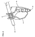
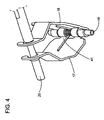
- valve arrangement in the closed position according to the invention is shown, which valve arrangement is located inside a body 12 with an inner chamber 13 in which a fluid, such as a liquid, a gas or the like, is received.
- a fluid such as a liquid, a gas or the like
- the body 12 comprises at least a first inlet/outlet passage 14 of the gas to the valve and at least a second inlet/outlet passage 15 and a third inlet/outlet passage 16 of the gas.
- the inner chamber 13 receives an inlet gas through the first inlet passage 14, coming from an inlet area and directed towards the second and third outlets 15, 16 communicating the chamber 13 with the outlet passages, or vice versa, and the inner chamber 13 comprises two inlet passages and one outlet passage.
- valve arrangement The function of the valve arrangement is to open and close a blocking element assembly 17, 18, such as a blade or valve, which arrangement controls the gas flow amount flowing through the inlet/outlet passages 14, 15, 16 of the inner chamber 13.
- the valve arrangement 11 comprises a first blade 17 and a second blade 18 which are joined at their proximal ends by means of a hinge pin 19 which is joined to a predetermined area of an inner wall of the inner chamber 13 close to a passage thereof, housed in the partition wall of the second and third outlet 15, 16 or the like for example.
- first and second blade 17, 18 are in physical contact with a first actuating pin 20 that can be axially actuated. Both distal ends of the first and second blade 17, 18 are kept separated by means of a first spring 21, such as a spring assembled on the first actuating pin 20.
- Both the first blade 17 and the second blade 18 substantially have the same constructive shape, such as a continuous broken line.
- the blades 17, 18 When both blades 17, 18 are assembled on both pins, the first actuating pin 20 and the hinge pin 19, the blades 17, 18 substantially adopt an amphora-type shape ending in a tip at the proximal end and in a narrow neck at the distal end.
- the width of the neck of the amphora-type shape corresponds to the axial dimension of the first spring 21.
- This amphora-type shape can be modified depending on the available space inside the inner chamber 13 and the constructive shape of both blades may differ for the same reason, i.e. available space within the area of the inner chamber 13.
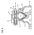
- the valve operates as follows: when the valve is closed, the first blade 17 and second blade 18 block the second outlet 15 and third outlet 16 of the inner chamber 13, respectively, as a result of the force exerted by the first spring 21 on the distal ends of both blades 17, 18.
- both the first and second blade 17, 18 are pivotably assembled on the hinge pin 19.
- valve arrangement can carry out the function of controlling the amount of gas to be recirculated as well as the function of selecting the circuit through which the gas must circulate, therefore it can replace two separate valves such as an EGR valve and a bypass valve generally used in common EGR systems.
- valve arrangement is likewise independent of the spatial situation of the inlet/outlet assembly 14, 15, 16.
- the blades 17, 18 can be manufactured of a material such as sheet metal, casting material, machining, sintering or by means of any other manufacturing process which allows obtaining the desired blade design.
- the blade-spring assembly 17, 18, 19 can be shifted along the first actuating pin 20 between the first stop and a second stop 22, 23 fixed thereto.
- Each blade 17, 18 is in physical contact with one of the stops 22, 23 of the first actuating pin 20, respectively.
- the stops 22, 23 being in contact option or the stops 22, 23 not being in contact option can be selected by design.
- both stops 22, 23 is a function of the design of the distal end of the blade 17, 18 and of the design of the first actuating pin 20 so that when the first actuating pin 20 moves in the valve opening direction, the stop comes into contact with the corresponding blade 17, 18, the first pin 20 transmitting the desired opening force.
- the first pin 20 can have two different diameters, the central part of the first pin 20 having a smaller diameter than the diameter of the ends of the pin 20 so as to abut with the blades 17, 18 only in the blade 17, 18 opening direction.
- the diameter of the first pin 20 is constant, stops such as washers integral with the pin 20 located in the outer parts of the blades 17, 18, being installed, obtaining the same effect as that described above.
- the designer has a certain degree of liberty to make a design allowing a blade 17, 18 to come into contact so that it can open with the first pin 20, transmitting the necessary force to overcome the closing forces of the spring 19, preventing the axial movement from tending to close the blade 17, 18; in this case there is no contact between the pin 20 and the blade 17, 18, and accordingly there is no transmission of force between pin 20 and blade 17, 18.
- the blades 17, 19 are closed by means of the action of the spring 19, which always tends to close them.
- a torsion spring 41 can additionally be located in the hinge pin 19 to help the spring 21 assembled on the first actuating pin 20 in its task of placing both the first and second blades 17, 18 on the corresponding valve seat.
- the spring 21 or the torsion spring 41, or both will be assembled, depending on the desired precision of the control of the gas flow through both second and third outlets 16, 15. It must also be noted that the existence of the spring 21 or the torsion spring 41 prevents the simultaneous opening of the second and third outlets 14, 15.
- the stop 22, 23, that is no longer in physical contact with its corresponding blade 17, 18 limits the movement of the first actuating pin 20 when it comes into contact with the corresponding inner wall of the body 12.
- the end of travel is not necessarily marked by the physical contact between the stop 22, 23 and the inner wall of the body 12, but rather the movement of the actuating pin 20 is controlled by the movement of the actuating motor.
- a blade 17, 18 can be located between the ends of a shift range of the first actuating pin 20, one of its ends being the rest, non-opening position of the valve, and the other end the maximum shift of the actuating pin 20, maximum opening of the valve.
- the degree of opening of a blade is related to the magnitude of the shift of the actuating pin 20, which defines the amount of gas going through the valve.
- This valve arrangement with an inlet area 14 and two outlet areas 15, 16 is particularly applicable, for example, for a heat exchanger of an EGR system with a bypass passage, the inlet area 14 being connected to the exhaust manifold and the outlet areas 15, 16 to the cooling module and to the bypass passage.
- valve arrangement 11 with two inlet areas and one outlet area is also applicable for a heat exchanger of an EGR system with a bypass passage, the two inlet areas being connected to the cooling module and to the bypass passage, and the outlet area to the intake manifold.
- the valve arrangement 11 can have two inlet areas and one outlet area such that the operation of the valve such that the gas flows from an inlet passage to the outlet passage and from the other inlet passage to the same outlet passage is by means of the same dynamics as that of the valve shown in Figures 1 to 4 .
- a blade 17, 18 additionally includes a sealing means 51, 52 to provide an improved sealing of the outlets 15, 16.
- the sealers 51, 52 can have a circular type shape or the like.
- the sealing disc 51, 52 is fixed to the blade 17, 18 by means of a ball joint type joint at both ends of the joint, one end corresponding to the joint to the disc and the other end to the joint to the blade 17, 18, allowing a degree of movement of the disc 51, 52 with regard to the blade, and in turn providing a sealed seat in the valve seat made in the body 12.
- a second spring can likewise be installed in the joint fixing the disc 51, 52 to the blade 17, 18 to prevent vibration of the disc caused by pressure pulses generated in the gas recirculation system.
- the described valve arrangement 11 can be installed in a body 12 comprising a single inlet and a single outlet, for example, for the EGR valve function in which only the amount of gas to be recirculated is controlled.
- the first actuating pin 20 can be axially shifted by means of, for example, a motor with a reduction gearbox coupled to an outlet in a rack and pinion system.
Landscapes
- Engineering & Computer Science (AREA)
- General Engineering & Computer Science (AREA)
- Mechanical Engineering (AREA)
- Chemical & Material Sciences (AREA)
- Combustion & Propulsion (AREA)
- Exhaust-Gas Circulating Devices (AREA)
- Lift Valve (AREA)
- Mechanically-Actuated Valves (AREA)
Priority Applications (1)
| Application Number | Priority Date | Filing Date | Title |
|---|---|---|---|
| PL08847517T PL2227646T3 (pl) | 2007-11-05 | 2008-11-05 | Układ zaworowy |
Applications Claiming Priority (2)
| Application Number | Priority Date | Filing Date | Title |
|---|---|---|---|
| ES200702906A ES2342640B1 (es) | 2007-11-05 | 2007-11-05 | Disposicion de valvula. |
| PCT/EP2008/065002 WO2009059999A1 (en) | 2007-11-05 | 2008-11-05 | Valve arrangement |
Publications (2)
| Publication Number | Publication Date |
|---|---|
| EP2227646A1 EP2227646A1 (en) | 2010-09-15 |
| EP2227646B1 true EP2227646B1 (en) | 2013-09-25 |
Family
ID=40291253
Family Applications (1)
| Application Number | Title | Priority Date | Filing Date |
|---|---|---|---|
| EP08847517.3A Not-in-force EP2227646B1 (en) | 2007-11-05 | 2008-11-05 | Valve arrangement |
Country Status (4)
| Country | Link |
|---|---|
| EP (1) | EP2227646B1 (pl) |
| ES (2) | ES2342640B1 (pl) |
| PL (1) | PL2227646T3 (pl) |
| WO (1) | WO2009059999A1 (pl) |
Families Citing this family (4)
| Publication number | Priority date | Publication date | Assignee | Title |
|---|---|---|---|---|
| DE102007058664A1 (de) | 2007-12-06 | 2009-06-10 | Gustav Wahler Gmbh U. Co. Kg | Doppelventil für eine Einrichtung zur Abgasrückführung |
| WO2011136701A1 (en) * | 2010-04-30 | 2011-11-03 | Volvo Lastvagnar Ab | Two flow passage valve |
| DE102014112336A1 (de) * | 2014-08-28 | 2016-03-03 | Pierburg Gmbh | Ventilvorrichtung für eine Verbrennungskraftmaschine |
| DE102015219197B4 (de) * | 2015-10-05 | 2019-07-04 | Conti Temic Microelectronic Gmbh | Pneumatisches Magnetventil |
Family Cites Families (5)
| Publication number | Priority date | Publication date | Assignee | Title |
|---|---|---|---|---|
| GB1023336A (en) * | 1963-05-23 | 1966-03-23 | Lucas Industries Ltd | Fluid controlling valves |
| FR1550343A (pl) * | 1967-11-07 | 1968-12-20 | ||
| DE2515194A1 (de) * | 1975-04-08 | 1976-10-21 | Krantz H Fa | Absperrvorrichtung |
| IT1044523B (it) * | 1975-07-18 | 1980-03-31 | Gilardini Spa | Valvola deviatrice a sei vie per liquidi |
| ES2249186B1 (es) * | 2005-03-01 | 2007-06-01 | Dayco Ensa, S.L. | Valvula by-pass y egr integrada. |
-
2007
- 2007-11-05 ES ES200702906A patent/ES2342640B1/es not_active Expired - Fee Related
-
2008
- 2008-11-05 PL PL08847517T patent/PL2227646T3/pl unknown
- 2008-11-05 WO PCT/EP2008/065002 patent/WO2009059999A1/en not_active Ceased
- 2008-11-05 EP EP08847517.3A patent/EP2227646B1/en not_active Not-in-force
- 2008-11-05 ES ES08847517.3T patent/ES2439959T3/es active Active
Also Published As
| Publication number | Publication date |
|---|---|
| EP2227646A1 (en) | 2010-09-15 |
| PL2227646T3 (pl) | 2014-01-31 |
| ES2342640B1 (es) | 2011-05-16 |
| ES2342640A1 (es) | 2010-07-09 |
| ES2439959T3 (es) | 2014-01-27 |
| WO2009059999A1 (en) | 2009-05-14 |
Similar Documents
| Publication | Publication Date | Title |
|---|---|---|
| US6955188B2 (en) | Switch valve for the exhaust gases of an internal combustion engine | |
| EP2321508B1 (en) | Butterfly valve for turbocharger systems | |
| US20200141309A1 (en) | Regulating device for an exhaust turbocharger | |
| EP2227646B1 (en) | Valve arrangement | |
| CN109072768B (zh) | 用于废气涡轮增压器的涡轮机 | |
| JPWO2008081803A1 (ja) | Egrバルブ装置 | |
| US9644753B2 (en) | Flapper exhaust diverter valve | |
| US7428897B2 (en) | Controllable two way valve device | |
| US7213587B2 (en) | Adjustable two-way valve device for a combustion engine | |
| EP1859156B1 (en) | By-pass and egr integrated valve | |
| CN109154229B (zh) | 用于废气涡轮增压器的涡轮机 | |
| JP5981411B2 (ja) | 自動車の排ガス流動用バイパス弁 | |
| EP2321517B1 (en) | Exhaust gas recirculation butterfly valve | |
| EP2313636A1 (en) | Exhaust gas recirculation valve actuator | |
| EP1640599B1 (en) | Exhaust gas recirculating system for internal combustion engines | |
| US12188567B2 (en) | Fluid circuit comprising three way valve with adjustment device | |
| JP2008528874A (ja) | 特に自動車用の排ガス熱交換器 | |
| CN222184955U (zh) | 废气再循环阀、发动机及车辆 | |
| US12372023B2 (en) | Ball valve thermostat assembly | |
| WO2006078607A1 (en) | Butterfly valve seal and bypass shutoff | |
| JP2020159514A (ja) | 制御バルブ | |
| US11353115B2 (en) | Rotary control valve having minimized internal fluid leak rate when closed |
Legal Events
| Date | Code | Title | Description |
|---|---|---|---|
| PUAI | Public reference made under article 153(3) epc to a published international application that has entered the european phase |
Free format text: ORIGINAL CODE: 0009012 |
|
| 17P | Request for examination filed |
Effective date: 20100605 |
|
| AK | Designated contracting states |
Kind code of ref document: A1 Designated state(s): AT BE BG CH CY CZ DE DK EE ES FI FR GB GR HR HU IE IS IT LI LT LU LV MC MT NL NO PL PT RO SE SI SK TR |
|
| AX | Request for extension of the european patent |
Extension state: AL BA MK RS |
|
| DAX | Request for extension of the european patent (deleted) | ||
| 17Q | First examination report despatched |
Effective date: 20110720 |
|
| GRAP | Despatch of communication of intention to grant a patent |
Free format text: ORIGINAL CODE: EPIDOSNIGR1 |
|
| RIC1 | Information provided on ipc code assigned before grant |
Ipc: F16K 11/16 20060101AFI20130308BHEP Ipc: F16K 31/528 20060101ALI20130308BHEP Ipc: F02M 25/07 20060101ALI20130308BHEP |
|
| INTG | Intention to grant announced |
Effective date: 20130410 |
|
| GRAS | Grant fee paid |
Free format text: ORIGINAL CODE: EPIDOSNIGR3 |
|
| GRAA | (expected) grant |
Free format text: ORIGINAL CODE: 0009210 |
|
| AK | Designated contracting states |
Kind code of ref document: B1 Designated state(s): AT BE BG CH CY CZ DE DK EE ES FI FR GB GR HR HU IE IS IT LI LT LU LV MC MT NL NO PL PT RO SE SI SK TR |
|
| REG | Reference to a national code |
Ref country code: GB Ref legal event code: FG4D |
|
| REG | Reference to a national code |
Ref country code: CH Ref legal event code: EP |
|
| REG | Reference to a national code |
Ref country code: AT Ref legal event code: REF Ref document number: 633846 Country of ref document: AT Kind code of ref document: T Effective date: 20131015 |
|
| REG | Reference to a national code |
Ref country code: IE Ref legal event code: FG4D |
|
| REG | Reference to a national code |
Ref country code: SE Ref legal event code: TRGR |
|
| REG | Reference to a national code |
Ref country code: DE Ref legal event code: R096 Ref document number: 602008027823 Country of ref document: DE Effective date: 20131121 |
|
| REG | Reference to a national code |
Ref country code: RO Ref legal event code: EPE |
|
| REG | Reference to a national code |
Ref country code: ES Ref legal event code: FG2A Ref document number: 2439959 Country of ref document: ES Kind code of ref document: T3 Effective date: 20140127 |
|
| PG25 | Lapsed in a contracting state [announced via postgrant information from national office to epo] |
Ref country code: LT Free format text: LAPSE BECAUSE OF FAILURE TO SUBMIT A TRANSLATION OF THE DESCRIPTION OR TO PAY THE FEE WITHIN THE PRESCRIBED TIME-LIMIT Effective date: 20130925 Ref country code: NO Free format text: LAPSE BECAUSE OF FAILURE TO SUBMIT A TRANSLATION OF THE DESCRIPTION OR TO PAY THE FEE WITHIN THE PRESCRIBED TIME-LIMIT Effective date: 20131225 Ref country code: HR Free format text: LAPSE BECAUSE OF FAILURE TO SUBMIT A TRANSLATION OF THE DESCRIPTION OR TO PAY THE FEE WITHIN THE PRESCRIBED TIME-LIMIT Effective date: 20130925 |
|
| REG | Reference to a national code |
Ref country code: PL Ref legal event code: T3 |
|
| REG | Reference to a national code |
Ref country code: AT Ref legal event code: MK05 Ref document number: 633846 Country of ref document: AT Kind code of ref document: T Effective date: 20130925 |
|
| REG | Reference to a national code |
Ref country code: NL Ref legal event code: VDEP Effective date: 20130925 |
|
| REG | Reference to a national code |
Ref country code: LT Ref legal event code: MG4D |
|
| PG25 | Lapsed in a contracting state [announced via postgrant information from national office to epo] |
Ref country code: FI Free format text: LAPSE BECAUSE OF FAILURE TO SUBMIT A TRANSLATION OF THE DESCRIPTION OR TO PAY THE FEE WITHIN THE PRESCRIBED TIME-LIMIT Effective date: 20130925 Ref country code: LV Free format text: LAPSE BECAUSE OF FAILURE TO SUBMIT A TRANSLATION OF THE DESCRIPTION OR TO PAY THE FEE WITHIN THE PRESCRIBED TIME-LIMIT Effective date: 20130925 Ref country code: SI Free format text: LAPSE BECAUSE OF FAILURE TO SUBMIT A TRANSLATION OF THE DESCRIPTION OR TO PAY THE FEE WITHIN THE PRESCRIBED TIME-LIMIT Effective date: 20130925 |
|
| PG25 | Lapsed in a contracting state [announced via postgrant information from national office to epo] |
Ref country code: BE Free format text: LAPSE BECAUSE OF FAILURE TO SUBMIT A TRANSLATION OF THE DESCRIPTION OR TO PAY THE FEE WITHIN THE PRESCRIBED TIME-LIMIT Effective date: 20130925 |
|
| REG | Reference to a national code |
Ref country code: DE Ref legal event code: R081 Ref document number: 602008027823 Country of ref document: DE Owner name: BORGWARNER EMISSIONS SYSTEMS SPAIN, S.L.UNIPER, ES Free format text: FORMER OWNER: DYTECH ENSA, S.L., PONTEVEDRA, ES Effective date: 20140224 |
|
| PG25 | Lapsed in a contracting state [announced via postgrant information from national office to epo] |
Ref country code: EE Free format text: LAPSE BECAUSE OF FAILURE TO SUBMIT A TRANSLATION OF THE DESCRIPTION OR TO PAY THE FEE WITHIN THE PRESCRIBED TIME-LIMIT Effective date: 20130925 Ref country code: NL Free format text: LAPSE BECAUSE OF FAILURE TO SUBMIT A TRANSLATION OF THE DESCRIPTION OR TO PAY THE FEE WITHIN THE PRESCRIBED TIME-LIMIT Effective date: 20130925 Ref country code: IS Free format text: LAPSE BECAUSE OF FAILURE TO SUBMIT A TRANSLATION OF THE DESCRIPTION OR TO PAY THE FEE WITHIN THE PRESCRIBED TIME-LIMIT Effective date: 20140125 Ref country code: SK Free format text: LAPSE BECAUSE OF FAILURE TO SUBMIT A TRANSLATION OF THE DESCRIPTION OR TO PAY THE FEE WITHIN THE PRESCRIBED TIME-LIMIT Effective date: 20130925 |
|
| PG25 | Lapsed in a contracting state [announced via postgrant information from national office to epo] |
Ref country code: AT Free format text: LAPSE BECAUSE OF FAILURE TO SUBMIT A TRANSLATION OF THE DESCRIPTION OR TO PAY THE FEE WITHIN THE PRESCRIBED TIME-LIMIT Effective date: 20130925 Ref country code: CY Free format text: LAPSE BECAUSE OF FAILURE TO SUBMIT A TRANSLATION OF THE DESCRIPTION OR TO PAY THE FEE WITHIN THE PRESCRIBED TIME-LIMIT Effective date: 20130925 |
|
| REG | Reference to a national code |
Ref country code: ES Ref legal event code: PC2A Owner name: BORGWARNER EMISSIONS SYSTEMS SPAIN, S.L. Effective date: 20140526 |
|
| REG | Reference to a national code |
Ref country code: DE Ref legal event code: R097 Ref document number: 602008027823 Country of ref document: DE |
|
| PG25 | Lapsed in a contracting state [announced via postgrant information from national office to epo] |
Ref country code: PT Free format text: LAPSE BECAUSE OF FAILURE TO SUBMIT A TRANSLATION OF THE DESCRIPTION OR TO PAY THE FEE WITHIN THE PRESCRIBED TIME-LIMIT Effective date: 20140127 |
|
| REG | Reference to a national code |
Ref country code: CH Ref legal event code: PL |
|
| PG25 | Lapsed in a contracting state [announced via postgrant information from national office to epo] |
Ref country code: MC Free format text: LAPSE BECAUSE OF FAILURE TO SUBMIT A TRANSLATION OF THE DESCRIPTION OR TO PAY THE FEE WITHIN THE PRESCRIBED TIME-LIMIT Effective date: 20130925 Ref country code: CH Free format text: LAPSE BECAUSE OF NON-PAYMENT OF DUE FEES Effective date: 20131130 Ref country code: LI Free format text: LAPSE BECAUSE OF NON-PAYMENT OF DUE FEES Effective date: 20131130 |
|
| PLBE | No opposition filed within time limit |
Free format text: ORIGINAL CODE: 0009261 |
|
| REG | Reference to a national code |
Ref country code: FR Ref legal event code: CD Owner name: BORGWARNER EMISSIONS SYSTEMS SPAIN, S.L.U., ES Effective date: 20140627 |
|
| STAA | Information on the status of an ep patent application or granted ep patent |
Free format text: STATUS: NO OPPOSITION FILED WITHIN TIME LIMIT |
|
| REG | Reference to a national code |
Ref country code: IE Ref legal event code: MM4A |
|
| 26N | No opposition filed |
Effective date: 20140626 |
|
| PG25 | Lapsed in a contracting state [announced via postgrant information from national office to epo] |
Ref country code: DK Free format text: LAPSE BECAUSE OF FAILURE TO SUBMIT A TRANSLATION OF THE DESCRIPTION OR TO PAY THE FEE WITHIN THE PRESCRIBED TIME-LIMIT Effective date: 20130925 |
|
| REG | Reference to a national code |
Ref country code: DE Ref legal event code: R097 Ref document number: 602008027823 Country of ref document: DE Effective date: 20140626 |
|
| PG25 | Lapsed in a contracting state [announced via postgrant information from national office to epo] |
Ref country code: IE Free format text: LAPSE BECAUSE OF NON-PAYMENT OF DUE FEES Effective date: 20131105 |
|
| PGFP | Annual fee paid to national office [announced via postgrant information from national office to epo] |
Ref country code: PL Payment date: 20140922 Year of fee payment: 7 |
|
| PGFP | Annual fee paid to national office [announced via postgrant information from national office to epo] |
Ref country code: GB Payment date: 20141027 Year of fee payment: 7 Ref country code: FR Payment date: 20141027 Year of fee payment: 7 Ref country code: CZ Payment date: 20141030 Year of fee payment: 7 Ref country code: SE Payment date: 20141107 Year of fee payment: 7 Ref country code: ES Payment date: 20141113 Year of fee payment: 7 Ref country code: RO Payment date: 20141023 Year of fee payment: 7 |
|
| PGFP | Annual fee paid to national office [announced via postgrant information from national office to epo] |
Ref country code: IT Payment date: 20141120 Year of fee payment: 7 |
|
| PG25 | Lapsed in a contracting state [announced via postgrant information from national office to epo] |
Ref country code: BG Free format text: LAPSE BECAUSE OF FAILURE TO SUBMIT A TRANSLATION OF THE DESCRIPTION OR TO PAY THE FEE WITHIN THE PRESCRIBED TIME-LIMIT Effective date: 20130925 Ref country code: HU Free format text: LAPSE BECAUSE OF FAILURE TO SUBMIT A TRANSLATION OF THE DESCRIPTION OR TO PAY THE FEE WITHIN THE PRESCRIBED TIME-LIMIT; INVALID AB INITIO Effective date: 20081105 Ref country code: LU Free format text: LAPSE BECAUSE OF NON-PAYMENT OF DUE FEES Effective date: 20131105 |
|
| PG25 | Lapsed in a contracting state [announced via postgrant information from national office to epo] |
Ref country code: GR Free format text: LAPSE BECAUSE OF NON-PAYMENT OF DUE FEES Effective date: 20130925 Ref country code: MT Free format text: LAPSE BECAUSE OF FAILURE TO SUBMIT A TRANSLATION OF THE DESCRIPTION OR TO PAY THE FEE WITHIN THE PRESCRIBED TIME-LIMIT Effective date: 20130925 |
|
| PGFP | Annual fee paid to national office [announced via postgrant information from national office to epo] |
Ref country code: TR Payment date: 20131105 Year of fee payment: 6 |
|
| GBPC | Gb: european patent ceased through non-payment of renewal fee |
Effective date: 20151105 |
|
| PG25 | Lapsed in a contracting state [announced via postgrant information from national office to epo] |
Ref country code: CZ Free format text: LAPSE BECAUSE OF NON-PAYMENT OF DUE FEES Effective date: 20151105 Ref country code: IT Free format text: LAPSE BECAUSE OF NON-PAYMENT OF DUE FEES Effective date: 20151105 |
|
| REG | Reference to a national code |
Ref country code: FR Ref legal event code: ST Effective date: 20160729 |
|
| PG25 | Lapsed in a contracting state [announced via postgrant information from national office to epo] |
Ref country code: SE Free format text: LAPSE BECAUSE OF NON-PAYMENT OF DUE FEES Effective date: 20151106 |
|
| PG25 | Lapsed in a contracting state [announced via postgrant information from national office to epo] |
Ref country code: GB Free format text: LAPSE BECAUSE OF NON-PAYMENT OF DUE FEES Effective date: 20151105 |
|
| PG25 | Lapsed in a contracting state [announced via postgrant information from national office to epo] |
Ref country code: FR Free format text: LAPSE BECAUSE OF NON-PAYMENT OF DUE FEES Effective date: 20151130 Ref country code: RO Free format text: LAPSE BECAUSE OF NON-PAYMENT OF DUE FEES Effective date: 20151105 |
|
| REG | Reference to a national code |
Ref country code: ES Ref legal event code: FD2A Effective date: 20161227 |
|
| PG25 | Lapsed in a contracting state [announced via postgrant information from national office to epo] |
Ref country code: ES Free format text: LAPSE BECAUSE OF NON-PAYMENT OF DUE FEES Effective date: 20151106 |
|
| PG25 | Lapsed in a contracting state [announced via postgrant information from national office to epo] |
Ref country code: PL Free format text: LAPSE BECAUSE OF NON-PAYMENT OF DUE FEES Effective date: 20151105 |
|
| PG25 | Lapsed in a contracting state [announced via postgrant information from national office to epo] |
Ref country code: TR Free format text: LAPSE BECAUSE OF NON-PAYMENT OF DUE FEES Effective date: 20151105 |
|
| PGFP | Annual fee paid to national office [announced via postgrant information from national office to epo] |
Ref country code: DE Payment date: 20171130 Year of fee payment: 10 |
|
| REG | Reference to a national code |
Ref country code: DE Ref legal event code: R119 Ref document number: 602008027823 Country of ref document: DE |
|
| PG25 | Lapsed in a contracting state [announced via postgrant information from national office to epo] |
Ref country code: DE Free format text: LAPSE BECAUSE OF NON-PAYMENT OF DUE FEES Effective date: 20190601 |