EP2227412B1 - Hydraulisches lenksystem für fahrzeuganhänger - Google Patents
Hydraulisches lenksystem für fahrzeuganhänger Download PDFInfo
- Publication number
- EP2227412B1 EP2227412B1 EP08801925.2A EP08801925A EP2227412B1 EP 2227412 B1 EP2227412 B1 EP 2227412B1 EP 08801925 A EP08801925 A EP 08801925A EP 2227412 B1 EP2227412 B1 EP 2227412B1
- Authority
- EP
- European Patent Office
- Prior art keywords
- pressure
- control line
- steering
- check valve
- steering system
- Prior art date
- Legal status (The legal status is an assumption and is not a legal conclusion. Google has not performed a legal analysis and makes no representation as to the accuracy of the status listed.)
- Not-in-force
Links
- 230000008859 change Effects 0.000 claims description 4
- 230000007257 malfunction Effects 0.000 claims description 4
- 239000012530 fluid Substances 0.000 claims description 3
- 230000004913 activation Effects 0.000 claims 2
- 230000001447 compensatory effect Effects 0.000 claims 1
- 230000009467 reduction Effects 0.000 description 4
- 230000001360 synchronised effect Effects 0.000 description 4
- 208000010201 Exanthema Diseases 0.000 description 2
- 238000006073 displacement reaction Methods 0.000 description 2
- 201000005884 exanthem Diseases 0.000 description 2
- 206010037844 rash Diseases 0.000 description 2
- 230000000903 blocking effect Effects 0.000 description 1
- 230000008878 coupling Effects 0.000 description 1
- 238000010168 coupling process Methods 0.000 description 1
- 238000005859 coupling reaction Methods 0.000 description 1
- 230000007812 deficiency Effects 0.000 description 1
- 230000006870 function Effects 0.000 description 1
- 238000012423 maintenance Methods 0.000 description 1
- 230000007935 neutral effect Effects 0.000 description 1
- 230000004044 response Effects 0.000 description 1
- 230000009885 systemic effect Effects 0.000 description 1
Images


Classifications
-
- B—PERFORMING OPERATIONS; TRANSPORTING
- B62—LAND VEHICLES FOR TRAVELLING OTHERWISE THAN ON RAILS
- B62D—MOTOR VEHICLES; TRAILERS
- B62D13/00—Steering specially adapted for trailers
- B62D13/02—Steering specially adapted for trailers for centrally-pivoted axles
- B62D13/025—Steering specially adapted for trailers for centrally-pivoted axles the pivoted movement being initiated by the coupling means between tractor and trailer
-
- B—PERFORMING OPERATIONS; TRANSPORTING
- B62—LAND VEHICLES FOR TRAVELLING OTHERWISE THAN ON RAILS
- B62D—MOTOR VEHICLES; TRAILERS
- B62D13/00—Steering specially adapted for trailers
- B62D13/04—Steering specially adapted for trailers for individually-pivoted wheels
Definitions
- the invention relates to a hydraulic steering system for vehicle trailers according to the feature configuration of the preamble of claim 1.
- the one pressure chamber of the control cylinder is connected via a first control line to the one pressure chamber of the at least one actuating cylinder, and the second pressure chamber of the control cylinder is connected via a second control line to the second pressure chamber of the respective actuating cylinder, wherein the at least one actuating cylinder is in turn formed as a synchronous cylinder and converts the control pressure differences in the first and second control line in a steering deflection of the respective trailer wheel group.
- a hydraulic steering system for vehicle trailers with at least one actuating cylinder for generating steering forces for a steerable wheel group of the trailer and at least one control cylinder which is connected via control lines to the actuating cylinder so that an operative connection for steering the wheel assembly is formed, and at least a hydraulic accumulator for maintaining a system pressure in the control lines, wherein a safety valve arrangement is provided which responds to a pressure change caused by a fault.
- a comparable hydraulic steering system is also by the DE 27 32 081 C3 demonstrated.
- WO 2007/137970 A1 is a corresponding to the next prior art hydraulic steering system for vehicle trailers, with at least one actuating cylinder for generating steering forces for a steerable wheel group of the trailer and with at least one control cylinder which is connected via control lines to the actuating cylinder so that an operative connection for steering the Group of wheels is formed, and with at least one hydraulic accumulator for maintaining a system pressure in the control lines, which caused by a fault pressure change in the one control line, a safety valve arrangement such responds that in the other control line a corresponding, compensating pressure change is effected.
- the safety valve arrangement used in the known solution has in the respectively provided control line to a pressure valve, which are each controlled by a hydraulic longitudinal piston assembly, which in turn gets notified as control input signals the steering and / or driving condition of the tractor via a corresponding measuring device.
- the known solution builds so far complicated and already due to the associated variety of parts disturbances in the operation are not excluded.
- the present invention seeks to provide a hydraulic steering system for vehicle trailers, which is highly secured against hazards caused by incidents.
- the safety valve arrangement comprises a 2/2-way valve, which is controllable at an inadmissible pressure loss in a control line causing accident in the switching state in which it connects the two control lines together.
- Such a centering biasing force can by springs on the relevant wheel or generated by the axle geometry. Disturbances are neutralized by this, so that there is neither the risk of uncontrolled steering deflections (such as when a pipe breaks a control line) or the risk of overloading the system (in case of blockage of the steering movement).
- the safety valve arrangement may include a pressure limiting valve, which releases a fluid path for a pressure reduction in the case of an accident causing an impermissible pressure buildup in a control line. In such embodiments, therefore, the risk is excluded that occurs in a mechanical blockage of the steering movement system overloading or damage.
- the arrangement may preferably be made such that the hydraulic accumulator is connected to the one or the other control line via a first and a second check valve which can be opened by the accumulator pressure and is provided as a refill reservoir for compensating leakage losses of the control lines.
- the system has a kind of bridge circuit with four check valves, wherein a bridge branch, to which the hydraulic accumulator and the first and the second check valve are connected, with the one or the other control line via a third and a fourth Check valve is connected, which can be opened by the pressure of the respective control line.
- the pressure relief valve may be inserted into the bridge branch so as to allow a pressure reduction from the junction between the third and fourth check valve to the connection point between the first and the second check valve in the open state. Since at the junction between the first and the second check valve and the hydraulic accumulator with the bridge branch is in communication, the pressure reduction of a relevant, overloaded by pressure control line both to the hydraulic accumulator out, as well as, via the first or the second check valve, to each to another control line.
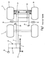
- Fig. 1 are a first wheel of an otherwise not shown vehicle trailer with 1 and a second, rear wheel group denoted by 3, which latter is designed as a so-called steering axle.
- An only schematically indicated trailer hitch 5 for connection to a train carriage, not shown, is mechanically connected to a drive cylinder 7 such that this synchronous cylinder acts as a so-called drawbar whose piston is displaced in one or the other direction in response to the steering movements of the towing vehicle.
- a first control line 9 and a second control line 11 is connected.
- Each control line 9 and 11 is connected to a hydraulic accumulator 13 and 15 and via shut-off elements 17 to a hydraulic pump 19 through which the control lines 9 and 11 and thus the hydraulic accumulators 13 and 15 are supplied with a system pressure.
- Pressure gauges which indicate the system pressure in the control line 9 and in the control line 11 are denoted by 19 and 20, respectively.
- the wheels 23 and 25 of the wheel group 3 are each connected to an actuating cylinder 27 and 29 such that the piston movements of these synchronous cylinders cause a steering deflection of the wheels 23, 25.
- the control lines 9 and 11 are connected to the pressure chambers of the actuating cylinder 27 and 29 so that pressure differences of the control lines 9 and 11 cause steering deflections of the wheels 23 and 25 in the same direction of steering.
- a movement of the piston 31 of the drive cylinder 7 in Fig. 2 to the right leads to an increase in pressure in the second control line 11 and thus in the pressure chambers 37 and 39 of the actuating cylinder 27 and 29 and thus to a steering deflection of the wheels 23 and 25 in the other steering sense.
- a security block 41 through which the first control line 9 from a terminal A1 to a terminal A2 passed through and the second control line 11 are passed from a terminal B1 forth to a terminal B2 through. Both control lines 9 and 11 are connected from the terminals A2 and B2 forth with the pressure chambers 33 and 39 only one actuating cylinder 27 shown.
- the safety block 41 does not intervene in the function of the steering circuit, ie the movements of the piston 31 of the control cylinder 7 generate via the terminals A1 and B1, the corresponding steering signals at the terminals A2 and B2.
- a filling valve 43 with a system pressure of, for example, 100 bar can be filled, whereby the previously biased example, 30 bar hydraulic accumulator 13 is charged, which is connected to the junction between a first check valve 45 and a second check valve 47 which are both set to a low opening pressure (for example 0.5 bar) and can be opened by the pressure of the hydraulic accumulator 13, so that the system pressure (pressure of the accumulator 13) is adjusted in the control lines 9 and 11 and the hydraulic accumulator 13 also serves as a refill Reservoir to compensate for leakage losses of the control lines 9 and 11 is effective.
- the connection point between the first check valve 45 and second check valve 47 and the switching line 49 of a pressure-actuated 2/2-way valve 51 in conjunction.
- this accident does not lead to an unwanted steering deflection of the steered wheel group.
- the safety valve arrangement counteracts a build-up pressure in a respective control line 9 or 11.
- a third check valve 53 and a fourth check valve 55 are provided, wherein the check valve 53 with the first control line 9 and the fourth check valve 55 with the second control line 11 and both connected and connected to each other by the pressure of the Control lines 9, 11 are openable.
- These check valves 45, 47, 53 and 55 form a kind of bridge circuit in such a way that their respective connection points are connected to each other via a bridge branch 57, in which a pressure relief valve 59 is inserted.
- Fig. 3 is a shut-off device designated 61, via which the system can be depressurized via the filling port F and emptied if necessary, for example, for maintenance or calibration measures.
Landscapes
- Engineering & Computer Science (AREA)
- Chemical & Material Sciences (AREA)
- Combustion & Propulsion (AREA)
- Transportation (AREA)
- Mechanical Engineering (AREA)
- Power Steering Mechanism (AREA)
Description
- Die Erfindung betrifft ein hydraulisches Lenksystem für Fahrzeuganhänger gemäß der Merkmalsausgestaltung des Oberbegriffes des Patentanspruches 1.
- Bekannte Lenksysteme, wie sie auf dem Markt frei erhältlich sind, werden üblicherweise in Verbindung mit zwangsgelenkten Achsen benutzt, die bei Anhängern insbesondere als heckseitige Radgruppe vorgesehen sind. Als Ansteuerzylinder ist hierbei ein sogenannter Deichselzylinder vorgesehen, der an der Kupplungsverbindung mit dem Zugfahrzeug so angeordnet ist, dass Lenkmanöver der Zugmaschine zu einer mechanischen Verschiebung des Kolbens des als Gleichgangzylinder ausgebildeten Ansteuerzylinders führen. Der eine Druckraum des Ansteuerzylinders ist über eine erste Steuerleitung mit dem einen Druckraum des zumindest einen Betätigungszylinders verbunden, und der zweite Druckraum des Ansteuerzylinders ist über eine zweite Steuerleitung mit dem zweiten Druckraum des betreffenden Betätigungszylinders verbunden, wobei der zumindest eine Betätigungszylinder wiederum als Gleichgangzylinder ausgebildet ist und die Steuerdruckdifferenzen in erster und zweiter Steuerleitung in einen Lenkausschlag der betreffenden Anhänger-Radgruppe umsetzt.
- Während diese bekannten Lenksysteme bei ungestörtem Normalbetrieb ein gutes Lenkverhalten von Anhängern ermöglichen, weisen derartige Systeme schwerwiegende Sicherheitsmängel auf, wenn im Fahrbetrieb ein Störfall auftritt. Wenn beispielsweise bei einem Bruch einer Steuerleitung oder einer Leckage an einer Anschlußverbindung einer Steuerleitung in dieser ein Druckverlust entsteht, der insbesondere von einem der Steuerleitung zugeordneten Hydrospeicher nicht ausgeglichen werden kann, dann führt ein derartiger unzulässiger Druckverlust zu einem ungewollten Lenkausschlag und zu einer entsprechend großen Betriebsgefahr. Ein anders gelagerter Störfall, bei dem ein zu lenkendes Rad an ein den Lenkausschlag blockierendes Hindernis an der Fahrbahn so anfährt, dass es gegen einen auszuführenden Lenkanschlag blockiert ist, führt wegen der dadurch bedingten Blockade der Kolbenbewegung des Betätigungszylinders zu einem entsprechenden Überdruck im System und damit zu einer Gefährdung der Systemkomponenten.
- Durch die
DE 31 36 657 A1 ist ein hydraulisches Lenksystem für Fahrzeuganhänger bekannt mit zumindest einem Betätigungszylinder zur Erzeugung von Lenkkräften für eine lenkbare Radgruppe des Anhängers und mit mindestens einem Ansteuerzylinder, der über Steuerleitungen mit dem Betätigungszylinder so verbunden ist, dass eine Wirkverbindung zur Lenkung der Radgruppe gebildet ist, und mit mindestens einem Hydrospeicher für das Aufrechterhalten eines Systemdruckes in den Steuerleitungen, wobei eine Sicherheitsventilanordnung vorgesehen ist, die bei durch einen Störfall bedingter Druckänderung anspricht. Ein vergleichbares hydraulisches Lenksystem ist auch durch dieDE 27 32 081 C3 aufgezeigt. - Durch die nachveröffentlichte
WO 2007/137970 A1 ist ein den nächsten Stand der Technik entsprechendes hydraulisches Lenksystem für Fahrzeuganhänger bekannt, mit zumindest einem Betätigungszylinder zur Erzeugung von Lenkkräften für eine lenkbare Radgruppe des Anhängers und mit mindestens einem Ansteuerzylinder, der über Steuerleitungen mit den Betätigungszylinder so verbunden ist, dass eine Wirkverbindung zur Lenkung der Radgruppe gebildet ist, und mit mindestens einem Hydrospeicher für das Aufrechterhalten eines Systemdrucks in den Steuerleitungen, wobei durch einen Störfall bedingter Druckänderung in der einen Steuerleitung eine Sicherheitsventilanordnung derart anspricht, dass in der anderen Steuerleitung eine entsprechende, kompensierende Druckänderung bewirkt wird. Die bei der bekannten Lösung eingesetzte Sicherheitsventilanordnung weist in der jeweils vorgesehenen Steuerleitung ein Druckventil auf, die jeweils von einer hydraulischen Längskolbenanordnung ansteuerbar sind, die wiederum als Steuereingangssignale den Lenk- und/oder Fahrzustand der Zugmaschine über eine entsprechende Messeinrichtung mitgeteilt bekommt. Die bekannte Lösung baut insoweit kompliziert auf und bereits aufgrund der damit einhergehenden Teilevielfalt sind Störungen im Betrieb nicht ausgeschlossen. - Im Hinblick auf diesen Stand der Technik liegt der Erfindung die Aufgabe zugrunde, ein hydraulisches Lenksystem für Fahrzeuganhänger zur Verfügung zu stellen, das gegen durch Störfälle verursachte Gefährdungen in hohem Maße gesichert ist.
- Erfindungsgemäß ist diese Aufgabe durch ein Lenksystem gelöst, das die Merkmale des Patentanspruches 1 in seiner Gesamtheit aufweist.
- Nach dem kennzeichnenden Teil des Anspruches 1 wird dies dadurch erreicht, dass die Sicherheitsventilanordnung ein 2/2-Wegeventil aufweist, das bei einem einen unzulässigen Druckverlust in einer Steuerleitung bewirkenden Störfall in den Schaltzustand steuerbar ist, in dem es die beiden Steuerleitungen miteinander verbindet. Dadurch wirken in einem solchen Störfall, beispielsweise einem Rohrbruch bei einer Steuerleitung, keine hydraulisch erzeugten Lenkkräfte auf die Radgruppe. Bei Anhängern, bei denen für die zu lenkenden Hinterränder eine äußere Kraft zur Zentrierung vorhanden ist, die zu lenkenden Hinterräder also in eine Neutral- oder Geradeausstellung leicht vorgespannt sind, stellen sich diese zu lenkenden Räder daher bei einem Rohrbruch einer betreffenden Steuerleitung in die Geradeaus-Position ein, so dass auch bei einem solchen Störfall eine Weiterfahrt, allerdings mit ungelenkter Radgruppe, möglich ist. Eine solche zentrierende Vorspannkraft kann durch Federn an der betreffenden Radgruppe oder durch die Achsgeometrie erzeugt werden. Störungen werden dadurch neutralisiert, so dass weder die Gefahr unkontrollierter Lenkausschläge (etwa bei Rohrbruch einer Steuerleitung) oder die Gefahr einer Systemüberlastung (bei Blockade der Lenkbewegung) besteht.
- Bei vorteilhaften Ausführungsbeispielen kann die Sicherheitsventilanordnung ein Druckbegrenzungsventil enthalten, das bei einem einen unzulässigen Druckaufbau in einer Steuerleitung bewirkenden Störfall einen Fluidweg für einen Druckabbau freigibt. Bei derartigen Ausführungsbeispielen ist daher auch die Gefahr ausgeschlossen, dass bei einer mechanischen Blockade der Lenkbewegung eine Systemüberlastung oder -beschädigung eintritt.
- Hinsichtlich des Hydrauliksystems kann die Anordnung vorzugsweise so getroffen sein, dass der Hydrospeicher über ein erstes und ein zweites durch den Speicherdruck öffenbares Rückschlagventil mit der einen bzw. der anderen Steuerleitung verbunden und als Nachfüll-Reservoir zum Ausgleich von Leckageverlusten der Steuerleitungen vorgesehen ist.
- Bei einer besonders vorteilhaften Ausführungsform weist das System eine Art Brückenschaltung mit vier Rückschlagventilen auf, wobei ein Brückenzweig, mit dem der Hydrospeicher und das erste und das zweite Rückschlagventil verbunden sind, mit der einen bzw. der anderen Steuerleitung auch über ein drittes bzw. ein viertes Rückschlagventil verbindbar ist, die durch den Druck der jeweiligen Steuerleitung öffenbar sind.
- Bei einer solchen Brückenschaltung kann das Druckbegrenzungsventil in den Brückenzweig so eingefügt sein, dass es im Öffnungszustand einen Druckabbau von der Verbindungsstelle zwischen drittem und viertem Rückschlagventil zur Verbindungsstelle zwischen dem ersten und dem zweiten Rückschlagventil hin ermöglicht. Da an der Verbindungsstelle zwischen dem ersten und dem zweiten Rückschlagventil auch der Hydrospeicher mit dem Brückenzweig in Verbindung ist, kann der Druckabbau von einer betreffenden, durch Überdruck belasteten Steuerleitung sowohl zum Hydrospeicher hin als auch, über das erste oder das zweite Rückschlagventil, zu der jeweils anderen Steuerleitung hin erfolgen.
- Bei besonders vorteilhaften Ausführungsbeispielen ist das 2/2-Wegeventil über eine Schaltleitung fluidbetätigbar, die mit dem Brückenzweig an der Verbindungsstelle mit dem ersten und dem zweiten Rückschlagventil verbunden ist, also an einer Stelle, an der der Druckabfall in der einen oder der anderen Steuerleitung über das erste Rückschlagventil oder das zweite Rückschlagventil an die Schaltleitung des 2/2-Wegeventils signalisiert wird. Nachstehend ist die Erfindung anhand der Zeichnung im Einzelnen erläutert. Es zeigen:
- Fig. 1
- eine stark schematisch vereinfachte, lediglich diagrammartig gezeichnete Darstellung der Radgruppen eines Fahrzeuganhängers, wobei die rückwärtige Radgruppe als sogenannte Lenkachse ausgebildet ist, versehen mit einem Lenksystem gemäß dem Stand der Technik;
- Fig. 2
- eine Darstellung des Hydrosystems des dem Stand der Technik entsprechenden Lenksystems von
Fig. 1 und - Fig. 3
- eine Darstellung des Systems eines Ausführungsbeispieles des erfindungsgemäßen Lenksystemes.
- In
Fig. 1 sind eine erste Radgruppe eines ansonsten nicht dargestellten Fahrzeuganhängers mit 1 und eine zweite, rückwärtige Radgruppe mit 3 bezeichnet, welch letztere als sogenannte Lenkachse ausgebildet ist. Eine lediglich schematisiert angedeutete Anhängerkupplung 5 für die Verbindung mit einem nicht dargestellten Zugwagen ist mit einem Ansteuerzylinder 7 mechanisch derart verbunden, dass dieser Gleichgangzylinder als sogenannter Deichselzylinder wirkt, dessen Kolben in Abhängigkeit von den Lenkbewegungen des Zugwagens in der einen oder anderen Richtung verschoben wird. Mit dem einen und dem anderen, an den Kolben angrenzenden Druckraum des Ansteuerzylinders 7 ist eine erste Steuerleitung 9 bzw. eine zweite Steuerleitung 11 verbunden. Jede Steuerleitung 9 und 11 ist mit einem Hydrospeicher 13 bzw. 15 sowie über Absperrorgane 17 mit einer Hydropumpe 19 verbunden, durch die die Steuerleitungen 9 und 11 und damit die Hydrospeicher 13 bzw. 15 mit einem Systemdruck versorgt sind. Manometer, die den Systemdruck in der Steuerleitung 9 und in der Steuerleitung 11 anzeigen, sind mit 19 bzw. 20 bezeichnet. - Die Räder 23 und 25 der Radgruppe 3 sind mit je einem Betätigungszylinder 27 bzw. 29 so verbunden, dass die Kolbenbewegungen dieser Gleichgangzylinder einen Lenkausschlag der Räder 23, 25 bewirken. Die Steuerleitungen 9 und 11 sind mit den Druckräumen der Betätigungszylinder 27 und 29 so verbunden, dass Druckdifferenzen der Steuerleitungen 9 und 11 Lenkausschläge der Räder 23 und 25 in jeweils gleichem Lenksinn bewirken. So führt eine durch Lenkbewegungen des Zugwagens über die Kupplung 5 übertragene Verschiebebewegung des Kolbens 31 des Ansteuerzylinders 7 in
Fig. 2 nach links zu einer Druckzunahme in der Steuerleitung 9 und damit in den Druckräumen 33 und 35 der Betätigungszylinder 27 bzw. 29, mit einem entsprechenden Lenkausschlag beider damit verbundener Räder 23 und 25 in gleichem Lenksinn. Eine Bewegung des Kolbens 31 des Ansteuerzylinders 7 inFig. 2 nach rechts führt zu einer Druckerhöhung in der zweiten Steuerleitung 11 und damit in den Druckräumen 37 und 39 der Betätigungszylinder 27 bzw. 29 und damit zu einem Lenkausschlag der Räder 23 und 25 im anderen Lenkungssinne. - Wenn es zu einem Rohrbruch oder anderweitigem Druckabfall in der ersten Steuerleitung 9 oder der zweiten Steuerleitung 11 kommt und wenn es sich dabei um einen solchen Störfall handelt, dass der Druckverlust nicht durch den einen Hydrospeicher 13 oder den anderen Hydrospeicher 15 ausgeglichen werden kann, kommt es zu einer ungewollten Verschiebung der Kolben beider Betätigungszylinder 27 und 29 und damit zu einem ungewollten, unkontrollierten Lenkausschlag der Räder 23 und 25.
- Kommt es andererseits zu einem Störfall, bei dem das Rad 23 und/oder 25 gegen eine gewollte Lenkbewegung mechanisch blockiert ist, entsteht im einen oder anderen Druckraum der Betätigungszylinder 27 bzw. 29 ein Überdruck, der, wenn er durch die Kapazität eines der Hydrospeicher 13 und 15 nicht kompensierbar ist, zur Systemgefährdung führt.
- Bei dem in
Fig. 3 dargestellten Ausführungsbeispiel der Erfindung weist das Lenksystem demgegenüber einen Sicherheitsblock 41 auf, durch den hindurch die erste Steuerleitung 9 von einem Anschluß A1 zu einem Anschluß A2 durchgehend hindurchgeführt und die zweite Steuerleitung 11 von einem Anschluß B1 her zu einem Anschluß B2 durchgehend hindurchgeführt sind. Beide Steuerleitungen 9 und 11 sind von den Anschlüssen A2 und B2 her mit den Druckräumen 33 bzw. 39 nur eines dargestellten Betätigungszylinders 27 verbunden. Bei Normalbetrieb, wenn kein Störfall gegeben ist, greift der Sicherheitsblock 41 nicht in die Funktion des Lenkkreises ein, d. h. die Bewegungen des Kolbens 31 des Ansteuerzylinders 7 erzeugen über die Anschlüsse A1 und B1 die entsprechenden Lenksignale an den Anschlüssen A2 und B2. - Von einem Füllanschluß F ist das System über ein Füllventil 43 mit einem Systemdruck von beispielsweise 100 bar befüllbar, wobei auch der zuvor mit beispielsweise 30 bar vorgespannte Hydrospeicher 13 geladen wird, der mit der Verbindungsstelle zwischen einem ersten Rückschlagventil 45 und einem zweiten Rückschlagventil 47 verbunden ist, die beide auf einen geringen Öffnungsdruck (beispielsweise 0,5 bar) eingestellt und durch den Druck des Hydrospeichers 13 öffenbar sind, so dass sich in den Steuerleitungen 9 und 11 der Systemdruck (Druck des Speichers 13) einstellt und der Hydrospeicher 13 auch als Nachfüll-Reservoir zum Ausgleich von Leckageverlusten der Steuerleitungen 9 und 11 wirksam ist. Mit der Verbindungsstelle zwischen erstem Rückschlagventil 45 und zweitem Rückschlagventil 47 ist auch die Schaltleitung 49 eines druckbetätigbaren 2/2-Wegeventils 51 in Verbindung. Dieses dient als Sicherheitsventil, über das erste Steuerleitung 9 und zweite Steuerleitung 11 unmittelbar miteinander verbindbar sind, wenn der Druck in der Schaltleitung 49 auf einen niedrigen Wert abfällt, beispielsweise auf einen Wert von 15 bar. Dies signalisiert den Störfall eines Rohrbruches oder einer anderen starken Leckage, die nicht durch den Hydrospeicher 13 ausgeglichen werden kann, wobei der Speicher 13 über das eine oder andere Rückschlagventil 45 oder 47 zur jeweils leckgeschlagenen Steuerleitung 9 oder 11 hin entladen wird. Durch die über das 2/2-Wegeventil 51 freigegebene Verbindung zwischen beiden Steuerleitungen 9 und 11 führt dieser Störfall nicht zu einem ungewollten Lenkausschlag der gelenkten Radgruppe 3.
- Bei einem andersartigen Störfall, d.h. der erwähnten mechanischen Blockade am Betätigungszylinder 27, wirkt die erfindungsgemäße Sicherheitsventilanordnung einem sich aufbauenden Überdruck in einer betreffenden Steuerleitung 9 oder 11 entgegen. Zu diesem Zweck sind ein drittes Rückschlagventil 53 und ein viertes Rückschlagventil 55 vorgesehen, wobei das Rückschlagventil 53 mit der ersten Steuerleitung 9 und das vierte Rückschlagventil 55 mit der zweiten Steuerleitung 11 sowie beide miteinander so verbunden und geschaltet sind, dass sie jeweils durch den Druck der Steuerleitungen 9, 11 öffenbar sind. Diese Rückschlagventile 45, 47, 53 und 55 bilden eine Art Brückenschaltung in der Weise, dass ihre jeweiligen Verbindungsstellen über einen Brückenzweig 57 miteinander verbunden sind, in den ein Druckbegrenzungsventil 59 eingefügt ist.
- Für den Störfall des Überdruckes in einer der Steuerleitungen 9 oder 11 ergibt sich dadurch folgende Funktionsweise: Wenn der Überdruck von einer der Steuerleitungen 9, 11 über das öffnende Rückschlagventil 53 oder 55 zum Brückenzweig 57 gelangt und der Überdruck den Ansteuerdruck (z. B. 150 bar) des Druckbegrenzungsventils 59 übersteigt, erfolgt der Druckabbau über den Brückenzweig 57 zur Verbindungsstelle zwischen erstem Rückschlagventil 45 und zweitem Rückschlagventil 47 und gleichzeitig zum Hydrospeicher 13. Dadurch kommt es zum Druckangleich in den Steuerleitungen 9 und 11, abgefedert durch den am Brückenzweig 57 ebenfalls angeschlossenen Hydrospeicher 13.
- In
Fig. 3 ist ein Absperrorgan mit 61 bezeichnet, über das das System bei Bedarf über den Füllanschluß F drucklos gemacht und entleert werden kann, beispielsweise für Wartungs- oder Kalibrierungsmaßnahmen.
Claims (6)
- Hydraulisches Lenksystem für Fahrzeuganhänger, mit zumindest einem Betätigungszylinder (27, 29) zur Erzeugung von Lenkkräften für eine lenkbare Radgruppe (3) des Anhängers und mit mindestens einem Ansteuerzylinder (7), der über Steuerleitungen (9, 11) mit dem Betätigungszylinder (27, 29) so verbunden ist, dass eine Wirkverbindung zur Lenkung der Radgruppe (3) gebildet ist, und mit mindestens einem Hydrospeicher (13) für das Aufrechterhalten eines Systemdruckes in den Steuerleitungen (9, 11), wozu bei durch einen Störfall bedingter Druckänderung in der einen Steuerleitung (9, 11) eine Sicherheitsventilanordnung (41) derart anspricht, dass in der anderen Steuerleitung (11, 9) eine entsprechende, kompensierende Druckänderung bewirkt wird, wobei die Sicherheitsventilanordnung (41) ein 2/2-Wegeventil (51) aufweist, das bei einem einen unzulässigen Druckverlust in einer Steuerleitung (9, 11) bewirkenden Störfall in den Schaltzustand steuerbar ist, in dem es die beiden Steuerleitungen (9, 11) miteinander verbindet.
- Lenksystem nach Anspruch 1, dadurch gekennzeichnet, dass die Sicherheitsventilanordnung (41) mindestens ein Druckbegrenzungsventil (59) enthält, das bei einem einen unzulässigen Druckaufbau in einer Steuerleitung (9, 11) bewirkenden Störfall einen Fluidweg für einen Druckabbau frei gibt.
- Lenksystem nach Anspruch 1 oder 2, dadurch gekennzeichnet, dass der Hydrospeicher (13) über ein erstes (45) und ein zweites (47) durch den Speicherdruck öffenbares Rückschlagventil (45, 47) mit der einen bzw. der anderen Steuerleitung (9, 11) verbunden und als Nachfüll-Reservoir zum Ausgleich von Leckageverlusten der Steuerleitungen (9, 11) vorgesehen ist.
- Lenksystem nach Anspruch 3, dadurch gekennzeichnet, dass in der Art einer Brückenschaltung ein Brückenzweig (57), mit dem der Hydrospeicher (13) und das erste (45) und das zweite Rückschlagventil(47) verbunden sind, mit der einen (9) bzw. der anderen Steuerleitung (11) auch über ein drittes (53) bzw. ein viertes Rückschlagventil (55) verbindbar ist, die durch den Druck der jeweiligen Steuerleitung (9, 11) öffenbar sind.
- Lenksystem nach Anspruch 4, dadurch gekennzeichnet, dass das Druckbegrenzungsventil (59) in den Brückenzweig (57) so eingefügt ist, dass es im Öffnungszustand einen Druckabbau von der Verbindungsstelle zwischen drittem (53) und viertem Rückschlagventil (55) zur Verbindungsstelle zwischen dem ersten (45) und dem zweiten Rückschlagventil (47) hin ermöglicht.
- Lenksystem nach Anspruch 5, dadurch gekennzeichnet, dass das 2/2-Wegeventil (51) über eine Schaltleitung (49) fluidbetätigbar ist, die mit dem Brückenzweig (57) an der Verbindungsstelle mit dem ersten (45) und dem zweiten Rückschlagventil (47) verbunden ist.
Applications Claiming Priority (2)
| Application Number | Priority Date | Filing Date | Title |
|---|---|---|---|
| DE200710056361 DE102007056361B3 (de) | 2007-11-22 | 2007-11-22 | Hydraulisches Lenksystem für Fahrzeuganhänger |
| PCT/EP2008/007351 WO2009065454A1 (de) | 2007-11-22 | 2008-09-09 | Hydraulisches lenksystem für fahrzeuganhänger |
Publications (2)
| Publication Number | Publication Date |
|---|---|
| EP2227412A1 EP2227412A1 (de) | 2010-09-15 |
| EP2227412B1 true EP2227412B1 (de) | 2013-05-22 |
Family
ID=39951690
Family Applications (1)
| Application Number | Title | Priority Date | Filing Date |
|---|---|---|---|
| EP08801925.2A Not-in-force EP2227412B1 (de) | 2007-11-22 | 2008-09-09 | Hydraulisches lenksystem für fahrzeuganhänger |
Country Status (3)
| Country | Link |
|---|---|
| EP (1) | EP2227412B1 (de) |
| DE (1) | DE102007056361B3 (de) |
| WO (1) | WO2009065454A1 (de) |
Families Citing this family (6)
| Publication number | Priority date | Publication date | Assignee | Title |
|---|---|---|---|---|
| AT508251B1 (de) * | 2009-12-18 | 2010-12-15 | Josef Ing Scharmueller | Fahrzeuganhänger mit einer zwangslenkung |
| FR2955305A1 (fr) * | 2010-01-20 | 2011-07-22 | Mauguin Citagri | Dispositif d'alignement d'un train roulant et procede correspondant. |
| DE102016011779A1 (de) | 2016-09-30 | 2018-04-05 | Hydac Accessories Gmbh | Bremsvorrichtung |
| DE102017210456A1 (de) * | 2017-06-22 | 2018-12-27 | Robert Bosch Gmbh | Hydraulisches System, Zweirad mit hydraulischem System und Verfahren zum Eingriff in das Lenkverhalten des Zweirads |
| CN114074810B (zh) * | 2020-08-12 | 2023-04-14 | 沈阳新松机器人自动化股份有限公司 | 一种具有自主救援功能的四向穿梭车系统 |
| CN112389541B (zh) * | 2020-12-02 | 2024-09-24 | 湖北三江航天万山特种车辆有限公司 | 一种多轴半挂车的多模式转向液压系统 |
Family Cites Families (4)
| Publication number | Priority date | Publication date | Assignee | Title |
|---|---|---|---|---|
| DE2732081C3 (de) * | 1977-07-15 | 1982-01-14 | Karl Kässbohrer Fahrzeugwerke GmbH, 7900 Ulm | Hydraulische Lenkübertragungsvorrichtung für Fahrzeuge |
| DE3136657A1 (de) * | 1981-09-16 | 1983-03-24 | Fahrzeugbau Langendorf, Heinrich Langendorf, 4355 Waltrop | "fahrzeug, insbesondere auflieger mit einer oder mehreren zwangsgelenkten achsen" |
| DE10222309B4 (de) * | 2002-05-18 | 2009-04-16 | Maschinenfabrik Kemper Gmbh & Co. Kg | Zwangslenkeinrichtung und Anhängefahrzeug |
| ITPD20060213A1 (it) * | 2006-05-29 | 2007-11-30 | Sansa Vini Steering Systems Di | Rimorchio o semi-rimorchio sterzante |
-
2007
- 2007-11-22 DE DE200710056361 patent/DE102007056361B3/de not_active Expired - Fee Related
-
2008
- 2008-09-09 EP EP08801925.2A patent/EP2227412B1/de not_active Not-in-force
- 2008-09-09 WO PCT/EP2008/007351 patent/WO2009065454A1/de not_active Ceased
Also Published As
| Publication number | Publication date |
|---|---|
| WO2009065454A1 (de) | 2009-05-28 |
| EP2227412A1 (de) | 2010-09-15 |
| DE102007056361B3 (de) | 2009-06-25 |
Similar Documents
| Publication | Publication Date | Title |
|---|---|---|
| DE102011017118B4 (de) | Vorrichtung zur Anpassung des Ist-Reifendrucks wenigstens eines Reifens eines Fahrzeugs an einen aktuellen Soll-Reifendruck während der Fahrt | |
| DE3606120C1 (de) | Einknickschutz-Vorrichtung fuer einen Sattelzug | |
| EP2380422B1 (de) | Hydraulische Anordnung | |
| DE10245618B4 (de) | Aktive Hinterachslenkung für einen Fahrzeugkran | |
| EP4081414B1 (de) | Ansteuervorrichtung | |
| DE102007056361B3 (de) | Hydraulisches Lenksystem für Fahrzeuganhänger | |
| DE3218070C2 (de) | Vorrichtung für einen Straßen-Gelenkzug zur Beeinflussung des Knickwinkels mittels Reibungsbremsen | |
| EP2675672B1 (de) | Mehrkreisschutzventil für eine druckluftversorgungseinrichtung eines fahrzeugs und verfahren zum betreiben eines mehrkreisschutzventils | |
| EP2272736A1 (de) | Steuerbare Achse für einen Anhänger | |
| DE10222309B4 (de) | Zwangslenkeinrichtung und Anhängefahrzeug | |
| DE19819404C2 (de) | Lenkvorrichtung | |
| DE3818617C2 (de) | ||
| DE3902810A1 (de) | Mehrachslenkanlage | |
| EP2772371B1 (de) | Anhängefahrzeug mit Tandemachse | |
| EP1761425B1 (de) | Hydraulische lenkung mit absicherung gegen unkontrollierte lenkbewegungen | |
| DE2748714C2 (de) | Vorrichtung zur Beeinflussung des Knickwinkels für einen Gelenkzug | |
| DE202011108878U1 (de) | Hinterachslenkvorrichtung für Anhängefahrzeuge, insbesondere für Schneidwerkswagen | |
| DE2935437C2 (de) | Ausbrechschutzvorrichtung für Gelenkbusse | |
| DE102006006141B4 (de) | Fahrzeuganhänger mit lenkbarer Achse | |
| EP3348430B1 (de) | Hydraulisches dämpfungssystem und gelenkfahrzeug mit einem derartigen dämpfungssystem | |
| DE102013016757A1 (de) | Lenksystem für eine Achse mit zumindest zwei Lenkbaren Rädern | |
| DE102004040940A1 (de) | Baugruppe für ein Fahrwerkstabilisierungssystem | |
| EP2343229A2 (de) | Lenkachse | |
| EP3290300B1 (de) | Mechanische lenkvorrichtung zur zwangslenkung von nutzfahrzeug-einzelradaufhängungen an sattelaufliegern abhängig vom relativgierwinkel zwischen zugfahrzeug und nachlauffahrzeug | |
| EP0477816B1 (de) | Hydraulische Lenkung für Fahrzeugachsen |
Legal Events
| Date | Code | Title | Description |
|---|---|---|---|
| PUAI | Public reference made under article 153(3) epc to a published international application that has entered the european phase |
Free format text: ORIGINAL CODE: 0009012 |
|
| 17P | Request for examination filed |
Effective date: 20100203 |
|
| AK | Designated contracting states |
Kind code of ref document: A1 Designated state(s): AT BE BG CH CY CZ DE DK EE ES FI FR GB GR HR HU IE IS IT LI LT LU LV MC MT NL NO PL PT RO SE SI SK TR |
|
| DAX | Request for extension of the european patent (deleted) | ||
| GRAP | Despatch of communication of intention to grant a patent |
Free format text: ORIGINAL CODE: EPIDOSNIGR1 |
|
| GRAS | Grant fee paid |
Free format text: ORIGINAL CODE: EPIDOSNIGR3 |
|
| GRAA | (expected) grant |
Free format text: ORIGINAL CODE: 0009210 |
|
| AK | Designated contracting states |
Kind code of ref document: B1 Designated state(s): AT BE BG CH CY CZ DE DK EE ES FI FR GB GR HR HU IE IS IT LI LT LU LV MC MT NL NO PL PT RO SE SI SK TR |
|
| REG | Reference to a national code |
Ref country code: GB Ref legal event code: FG4D Free format text: NOT ENGLISH |
|
| REG | Reference to a national code |
Ref country code: CH Ref legal event code: EP |
|
| REG | Reference to a national code |
Ref country code: AT Ref legal event code: REF Ref document number: 613065 Country of ref document: AT Kind code of ref document: T Effective date: 20130615 |
|
| REG | Reference to a national code |
Ref country code: IE Ref legal event code: FG4D Free format text: LANGUAGE OF EP DOCUMENT: GERMAN |
|
| REG | Reference to a national code |
Ref country code: DE Ref legal event code: R096 Ref document number: 502008009988 Country of ref document: DE Effective date: 20130718 |
|
| REG | Reference to a national code |
Ref country code: LT Ref legal event code: MG4D |
|
| PG25 | Lapsed in a contracting state [announced via postgrant information from national office to epo] |
Ref country code: PT Free format text: LAPSE BECAUSE OF FAILURE TO SUBMIT A TRANSLATION OF THE DESCRIPTION OR TO PAY THE FEE WITHIN THE PRESCRIBED TIME-LIMIT Effective date: 20130923 Ref country code: NO Free format text: LAPSE BECAUSE OF FAILURE TO SUBMIT A TRANSLATION OF THE DESCRIPTION OR TO PAY THE FEE WITHIN THE PRESCRIBED TIME-LIMIT Effective date: 20130822 Ref country code: SE Free format text: LAPSE BECAUSE OF FAILURE TO SUBMIT A TRANSLATION OF THE DESCRIPTION OR TO PAY THE FEE WITHIN THE PRESCRIBED TIME-LIMIT Effective date: 20130522 Ref country code: FI Free format text: LAPSE BECAUSE OF FAILURE TO SUBMIT A TRANSLATION OF THE DESCRIPTION OR TO PAY THE FEE WITHIN THE PRESCRIBED TIME-LIMIT Effective date: 20130522 Ref country code: IS Free format text: LAPSE BECAUSE OF FAILURE TO SUBMIT A TRANSLATION OF THE DESCRIPTION OR TO PAY THE FEE WITHIN THE PRESCRIBED TIME-LIMIT Effective date: 20130922 Ref country code: ES Free format text: LAPSE BECAUSE OF FAILURE TO SUBMIT A TRANSLATION OF THE DESCRIPTION OR TO PAY THE FEE WITHIN THE PRESCRIBED TIME-LIMIT Effective date: 20130902 Ref country code: GR Free format text: LAPSE BECAUSE OF FAILURE TO SUBMIT A TRANSLATION OF THE DESCRIPTION OR TO PAY THE FEE WITHIN THE PRESCRIBED TIME-LIMIT Effective date: 20130823 Ref country code: LT Free format text: LAPSE BECAUSE OF FAILURE TO SUBMIT A TRANSLATION OF THE DESCRIPTION OR TO PAY THE FEE WITHIN THE PRESCRIBED TIME-LIMIT Effective date: 20130522 Ref country code: SI Free format text: LAPSE BECAUSE OF FAILURE TO SUBMIT A TRANSLATION OF THE DESCRIPTION OR TO PAY THE FEE WITHIN THE PRESCRIBED TIME-LIMIT Effective date: 20130522 |
|
| REG | Reference to a national code |
Ref country code: NL Ref legal event code: VDEP Effective date: 20130522 |
|
| PG25 | Lapsed in a contracting state [announced via postgrant information from national office to epo] |
Ref country code: BG Free format text: LAPSE BECAUSE OF FAILURE TO SUBMIT A TRANSLATION OF THE DESCRIPTION OR TO PAY THE FEE WITHIN THE PRESCRIBED TIME-LIMIT Effective date: 20130822 Ref country code: HR Free format text: LAPSE BECAUSE OF FAILURE TO SUBMIT A TRANSLATION OF THE DESCRIPTION OR TO PAY THE FEE WITHIN THE PRESCRIBED TIME-LIMIT Effective date: 20130522 Ref country code: PL Free format text: LAPSE BECAUSE OF FAILURE TO SUBMIT A TRANSLATION OF THE DESCRIPTION OR TO PAY THE FEE WITHIN THE PRESCRIBED TIME-LIMIT Effective date: 20130522 |
|
| PG25 | Lapsed in a contracting state [announced via postgrant information from national office to epo] |
Ref country code: LV Free format text: LAPSE BECAUSE OF FAILURE TO SUBMIT A TRANSLATION OF THE DESCRIPTION OR TO PAY THE FEE WITHIN THE PRESCRIBED TIME-LIMIT Effective date: 20130522 |
|
| PG25 | Lapsed in a contracting state [announced via postgrant information from national office to epo] |
Ref country code: DK Free format text: LAPSE BECAUSE OF FAILURE TO SUBMIT A TRANSLATION OF THE DESCRIPTION OR TO PAY THE FEE WITHIN THE PRESCRIBED TIME-LIMIT Effective date: 20130522 Ref country code: CZ Free format text: LAPSE BECAUSE OF FAILURE TO SUBMIT A TRANSLATION OF THE DESCRIPTION OR TO PAY THE FEE WITHIN THE PRESCRIBED TIME-LIMIT Effective date: 20130522 Ref country code: SK Free format text: LAPSE BECAUSE OF FAILURE TO SUBMIT A TRANSLATION OF THE DESCRIPTION OR TO PAY THE FEE WITHIN THE PRESCRIBED TIME-LIMIT Effective date: 20130522 Ref country code: EE Free format text: LAPSE BECAUSE OF FAILURE TO SUBMIT A TRANSLATION OF THE DESCRIPTION OR TO PAY THE FEE WITHIN THE PRESCRIBED TIME-LIMIT Effective date: 20130522 |
|
| PG25 | Lapsed in a contracting state [announced via postgrant information from national office to epo] |
Ref country code: NL Free format text: LAPSE BECAUSE OF FAILURE TO SUBMIT A TRANSLATION OF THE DESCRIPTION OR TO PAY THE FEE WITHIN THE PRESCRIBED TIME-LIMIT Effective date: 20130522 Ref country code: RO Free format text: LAPSE BECAUSE OF FAILURE TO SUBMIT A TRANSLATION OF THE DESCRIPTION OR TO PAY THE FEE WITHIN THE PRESCRIBED TIME-LIMIT Effective date: 20130522 |
|
| PLBE | No opposition filed within time limit |
Free format text: ORIGINAL CODE: 0009261 |
|
| STAA | Information on the status of an ep patent application or granted ep patent |
Free format text: STATUS: NO OPPOSITION FILED WITHIN TIME LIMIT |
|
| BERE | Be: lapsed |
Owner name: HYDAC SYSTEM G.M.B.H. Effective date: 20130930 |
|
| 26N | No opposition filed |
Effective date: 20140225 |
|
| PG25 | Lapsed in a contracting state [announced via postgrant information from national office to epo] |
Ref country code: MC Free format text: LAPSE BECAUSE OF FAILURE TO SUBMIT A TRANSLATION OF THE DESCRIPTION OR TO PAY THE FEE WITHIN THE PRESCRIBED TIME-LIMIT Effective date: 20130522 |
|
| REG | Reference to a national code |
Ref country code: CH Ref legal event code: PL |
|
| GBPC | Gb: european patent ceased through non-payment of renewal fee |
Effective date: 20130909 |
|
| REG | Reference to a national code |
Ref country code: DE Ref legal event code: R097 Ref document number: 502008009988 Country of ref document: DE Effective date: 20140225 |
|
| REG | Reference to a national code |
Ref country code: IE Ref legal event code: MM4A |
|
| PG25 | Lapsed in a contracting state [announced via postgrant information from national office to epo] |
Ref country code: BE Free format text: LAPSE BECAUSE OF NON-PAYMENT OF DUE FEES Effective date: 20130930 Ref country code: LI Free format text: LAPSE BECAUSE OF NON-PAYMENT OF DUE FEES Effective date: 20130930 Ref country code: CH Free format text: LAPSE BECAUSE OF NON-PAYMENT OF DUE FEES Effective date: 20130930 Ref country code: GB Free format text: LAPSE BECAUSE OF NON-PAYMENT OF DUE FEES Effective date: 20130909 Ref country code: IE Free format text: LAPSE BECAUSE OF NON-PAYMENT OF DUE FEES Effective date: 20130909 |
|
| PG25 | Lapsed in a contracting state [announced via postgrant information from national office to epo] |
Ref country code: CY Free format text: LAPSE BECAUSE OF FAILURE TO SUBMIT A TRANSLATION OF THE DESCRIPTION OR TO PAY THE FEE WITHIN THE PRESCRIBED TIME-LIMIT Effective date: 20130522 Ref country code: MT Free format text: LAPSE BECAUSE OF FAILURE TO SUBMIT A TRANSLATION OF THE DESCRIPTION OR TO PAY THE FEE WITHIN THE PRESCRIBED TIME-LIMIT Effective date: 20130522 Ref country code: TR Free format text: LAPSE BECAUSE OF FAILURE TO SUBMIT A TRANSLATION OF THE DESCRIPTION OR TO PAY THE FEE WITHIN THE PRESCRIBED TIME-LIMIT Effective date: 20130522 |
|
| PG25 | Lapsed in a contracting state [announced via postgrant information from national office to epo] |
Ref country code: LU Free format text: LAPSE BECAUSE OF NON-PAYMENT OF DUE FEES Effective date: 20130909 Ref country code: HU Free format text: LAPSE BECAUSE OF FAILURE TO SUBMIT A TRANSLATION OF THE DESCRIPTION OR TO PAY THE FEE WITHIN THE PRESCRIBED TIME-LIMIT; INVALID AB INITIO Effective date: 20080909 |
|
| REG | Reference to a national code |
Ref country code: FR Ref legal event code: PLFP Year of fee payment: 9 |
|
| REG | Reference to a national code |
Ref country code: FR Ref legal event code: PLFP Year of fee payment: 10 |
|
| REG | Reference to a national code |
Ref country code: FR Ref legal event code: PLFP Year of fee payment: 11 |
|
| PGFP | Annual fee paid to national office [announced via postgrant information from national office to epo] |
Ref country code: DE Payment date: 20220930 Year of fee payment: 15 Ref country code: AT Payment date: 20220901 Year of fee payment: 15 |
|
| PGFP | Annual fee paid to national office [announced via postgrant information from national office to epo] |
Ref country code: FR Payment date: 20220805 Year of fee payment: 15 |
|
| PGFP | Annual fee paid to national office [announced via postgrant information from national office to epo] |
Ref country code: IT Payment date: 20220915 Year of fee payment: 15 |
|
| REG | Reference to a national code |
Ref country code: DE Ref legal event code: R119 Ref document number: 502008009988 Country of ref document: DE |
|
| REG | Reference to a national code |
Ref country code: AT Ref legal event code: MM01 Ref document number: 613065 Country of ref document: AT Kind code of ref document: T Effective date: 20230909 |
|
| PG25 | Lapsed in a contracting state [announced via postgrant information from national office to epo] |
Ref country code: AT Free format text: LAPSE BECAUSE OF NON-PAYMENT OF DUE FEES Effective date: 20230909 |
|
| PG25 | Lapsed in a contracting state [announced via postgrant information from national office to epo] |
Ref country code: FR Free format text: LAPSE BECAUSE OF NON-PAYMENT OF DUE FEES Effective date: 20230930 Ref country code: DE Free format text: LAPSE BECAUSE OF NON-PAYMENT OF DUE FEES Effective date: 20240403 Ref country code: AT Free format text: LAPSE BECAUSE OF NON-PAYMENT OF DUE FEES Effective date: 20230909 |
|
| PG25 | Lapsed in a contracting state [announced via postgrant information from national office to epo] |
Ref country code: IT Free format text: LAPSE BECAUSE OF NON-PAYMENT OF DUE FEES Effective date: 20230909 |
|
| PG25 | Lapsed in a contracting state [announced via postgrant information from national office to epo] |
Ref country code: IT Free format text: LAPSE BECAUSE OF NON-PAYMENT OF DUE FEES Effective date: 20230909 |