EP2226884A1 - Lateral-striped solid-oxide fuel cell - Google Patents
Lateral-striped solid-oxide fuel cell Download PDFInfo
- Publication number
- EP2226884A1 EP2226884A1 EP08863757A EP08863757A EP2226884A1 EP 2226884 A1 EP2226884 A1 EP 2226884A1 EP 08863757 A EP08863757 A EP 08863757A EP 08863757 A EP08863757 A EP 08863757A EP 2226884 A1 EP2226884 A1 EP 2226884A1
- Authority
- EP
- European Patent Office
- Prior art keywords
- electrode layer
- insulating substrate
- electrically insulating
- solid oxide
- interconnector
- Prior art date
- Legal status (The legal status is an assumption and is not a legal conclusion. Google has not performed a legal analysis and makes no representation as to the accuracy of the status listed.)
- Withdrawn
Links
Images













Classifications
-
- H—ELECTRICITY
- H01—ELECTRIC ELEMENTS
- H01M—PROCESSES OR MEANS, e.g. BATTERIES, FOR THE DIRECT CONVERSION OF CHEMICAL ENERGY INTO ELECTRICAL ENERGY
- H01M8/00—Fuel cells; Manufacture thereof
- H01M8/10—Fuel cells with solid electrolytes
- H01M8/12—Fuel cells with solid electrolytes operating at high temperature, e.g. with stabilised ZrO2 electrolyte
- H01M8/1213—Fuel cells with solid electrolytes operating at high temperature, e.g. with stabilised ZrO2 electrolyte characterised by the electrode/electrolyte combination or the supporting material
-
- H—ELECTRICITY
- H01—ELECTRIC ELEMENTS
- H01M—PROCESSES OR MEANS, e.g. BATTERIES, FOR THE DIRECT CONVERSION OF CHEMICAL ENERGY INTO ELECTRICAL ENERGY
- H01M8/00—Fuel cells; Manufacture thereof
- H01M8/02—Details
- H01M8/0202—Collectors; Separators, e.g. bipolar separators; Interconnectors
- H01M8/0204—Non-porous and characterised by the material
-
- H—ELECTRICITY
- H01—ELECTRIC ELEMENTS
- H01M—PROCESSES OR MEANS, e.g. BATTERIES, FOR THE DIRECT CONVERSION OF CHEMICAL ENERGY INTO ELECTRICAL ENERGY
- H01M8/00—Fuel cells; Manufacture thereof
- H01M8/10—Fuel cells with solid electrolytes
- H01M8/12—Fuel cells with solid electrolytes operating at high temperature, e.g. with stabilised ZrO2 electrolyte
- H01M8/1286—Fuel cells applied on a support, e.g. miniature fuel cells deposited on silica supports
-
- H—ELECTRICITY
- H01—ELECTRIC ELEMENTS
- H01M—PROCESSES OR MEANS, e.g. BATTERIES, FOR THE DIRECT CONVERSION OF CHEMICAL ENERGY INTO ELECTRICAL ENERGY
- H01M8/00—Fuel cells; Manufacture thereof
- H01M8/24—Grouping of fuel cells, e.g. stacking of fuel cells
- H01M8/241—Grouping of fuel cells, e.g. stacking of fuel cells with solid or matrix-supported electrolytes
- H01M8/2425—High-temperature cells with solid electrolytes
- H01M8/2428—Grouping by arranging unit cells on a surface of any form, e.g. planar or tubular
-
- Y—GENERAL TAGGING OF NEW TECHNOLOGICAL DEVELOPMENTS; GENERAL TAGGING OF CROSS-SECTIONAL TECHNOLOGIES SPANNING OVER SEVERAL SECTIONS OF THE IPC; TECHNICAL SUBJECTS COVERED BY FORMER USPC CROSS-REFERENCE ART COLLECTIONS [XRACs] AND DIGESTS
- Y02—TECHNOLOGIES OR APPLICATIONS FOR MITIGATION OR ADAPTATION AGAINST CLIMATE CHANGE
- Y02E—REDUCTION OF GREENHOUSE GAS [GHG] EMISSIONS, RELATED TO ENERGY GENERATION, TRANSMISSION OR DISTRIBUTION
- Y02E60/00—Enabling technologies; Technologies with a potential or indirect contribution to GHG emissions mitigation
- Y02E60/30—Hydrogen technology
- Y02E60/50—Fuel cells
Definitions
- the present invention relates to a segmented-in-series solid oxide fuel cell, and more specifically, to a segmented-in-series solid oxide fuel cell comprising a porous electrically insulating substrate having a fuel flow path, provided therein, and a plurality of solid oxide fuel cells disposed in a segmented-in-series fashion, provided on a pair of surfaces of the porous electrically insulating substrate, opposing each other, and a segmented-in-series solid oxide fuel cell comprising a porous electrically insulating substrate having an air flow path, provided therein, and a plurality of solid oxide fuel cells disposed in a segmented-in-series fashion, provided on a pair of surfaces of the porous electrically insulating substrate, opposing each other.
- the solid oxide fuel cell is hereinafter termed merely as "the cells" for short as appropriate.
- a segmented-in-series solid oxide fuel cell is a fuel cell of a type wherein a plurality of cells disposed in a segmented-in-series fashion are made up by disposing a fuel electrode layer, and an air electrode layer in such a way as to cause an electrolytic material composed of an electrolyte to be sandwiched therebetween while disposing an interconnector on a side of the cell, adjacent to the fuel electrode layer, and an interconnector on a side of the cell, adjacent to the air electrode layer, as appropriate.
- the segmented-in-series oxide fuel type cell includes a cylindrical type as described in JP Hei 10 (1998) - 3932 - A (hereinafter referred to as Patent Document 1), a hollow flat type as described in JP 2006 -19059 - A (hereinafter referred to as Patent Document 2), and so forth.
- the segmented-in-series solid oxide fuel cell of the hollow flat type is made up by disposing the plurality of the cells on the respective flat surfaces of a porous electrically insulating substrate, in a hollow flat sectional shape, that is, an electrically insulating substrate, more specifically, on each of a pair of the surfaces thereof, opposing each other, and by electrically connecting adjacent cells with each other via an interconnector.
- a hollow part of the electrically insulating substrate in the hollow flat sectional shape is formed inside the substrate, and the hollow part normally serves as a gas flow path for flowing fuel or air from a port at one end thereof toward a port at the other end thereof (as a fuel flow path in the case of flowing fuel, and as an air flow path in the case of flowing air).
- a current output position can be optionally set, however, in practical application, the current output position is set at the same end of the electrically insulating substrate.
- a current at the time of operation is caused to flow from an end of the electrically insulating substrate, in the direction of a lineup of the plurality of the cells disposed on the top surface of the electrically insulating substrate, and to an end of one of the plurality of the cells disposed on the back surface of the electrically insulating substrate (that is, to an end of the electrically insulating substrate, on the back surface side thereof) in the direction opposite from the direction of a current flow on the top surface side.
- Figs. 1(a) to 1(c) are views showing an example of the structure of a segmented-in-series solid oxide fuel cell of the hollow flat type, in which Fig. 1(a) is a perspective view, and Fig. 1(b) is a plan view.
- a plurality of cells 5, each having a three-layered structure comprised of a fuel electrode layer, an electrolyte layer, and an air electrode layer, are disposed on both an upper surface and an underside surface of an electrically insulating substrate 1 in a hollow flat sectional shape, namely, both the top surface, and the back surface thereof.
- the segmented-in-series solid oxide fuel cell is made up by electrically connecting the adjacent cells in series with each other through the intermediary of an interconnector.
- a fuel flow path S extending from a fuel feed port to a fuel discharge port, provided in the electrically insulating substrate 1, in parallel with the lineup of the cells 5, as indicated by the arrow ( ⁇ ) in Fig. 1(a) .
- the number of the fuel flow paths S is not limited to one, and a plurality thereof may be provided, and Fig. 1(c) illustrates an example where eight pieces of the fuel flow paths S are provided.
- the cross sectional shape of the electrically insulating substrate 1 is not limited thereto, and may be square, elliptical, and so forth, as appropriate.
- Fig. 1(a) there is shown a current flow during operation in a mode where current is turned around at the end of the electrically insulating substrate 1, in the direction of a fuel flow, that is, at the fuel discharge port.
- the segmented-in-series solid oxide fuel cell is structured such that a current is caused to flow from a proximal end of the electrically insulating substrate 1 to an end on the opposite side thereof, that is, from the cell 5 disposed at a distal end on the back surface of the electrically insulating substrate 1 to the cell 5 disposed at a distal end on the top surface thereof.
- a state in which a current flowing toward one end of the electrically insulating substrate, on one of the surfaces thereof, continues to flow to the other surface thereof, at the one end, and subsequently, the current flows toward the other end of the electrically insulating substrate is hereinafter referred to as "a current is turned around" in the present specification.
- a structure for causing this state is called a current-turnaround structure where appropriate.
- top surface, and the back surface are used in referring to both the top and back surfaces of the electrically insulating substrate, or both surfaces of the top surface, and the back surface thereof, and so forth, however, it is to be understood that those terms are used just for the sake of convenience in explanation, and in, for example, the perspective view of Fig. 1(a) , an upper surface, that is, a visible surface is referred to as the top surface, whereas an underside surface, that is, an invisible surface is referred to as the back surface, and therefore, if the electrically insulating substrate is turned upside down, the back surface in Fig. 1(a) will be the top surface while the top surface in Fig. 1(a) will be the back surface.
- a plurality of cells 25 are disposed on an electrically insulating substrate 28 such that the cells 25 are electrically connected in series with each other, and a current inlet and a current outlet are positioned at respective ends of the electrically insulating substrate 28, as shown in Fig. 25 .
- a lead wire for use in outputting current through the electrically insulating substrate 28 up to a plus terminal at the right end thereof, so that there are needs for various design ideas such as a measure for preventing the lead wire from being disengaged, and so forth.
- the present invention has been developed in order to solve problems described as above with the segmented in series solid oxide fuel cell, and it is an object of the present invention to provide a segmented-in-series solid oxide fuel cell having a safe and highly reliable structure capable of exhibiting stable power generation performance at a high fuel utilization ratio, serving as means for turning around current at an end of the segmented-in-series solid oxide fuel cell, on a current turnaround side thereof.
- a segmented-in-series solid oxide fuel cell comprising a porous electrically insulating substrate having (a) a fuel flow path extending from a fuel feed port to a fuel discharge port, provided therein, and a pair of the top and back surfaces, in parallel with the fuel flow path, together with a pair of side-faces of the porous electrically insulating substrate, in the transverse direction thereof, provided on the exterior thereof, wherein (b) a plurality of solid oxide fuel cells made up by sequentially stacking an interconnector adjacent to a fuel electrode layer, the fuel electrode layer, an electrolyte layer, an air electrode layer, and an interconnector adjacent to the air electrode layer in that order so as to be in parallel with the fuel flow path are disposed at intervals on the pair of the top and back surfaces, respectively, and (c) the plurality of the solid oxide fuel cells are structured such that adjacent solid oxide fuel cells are electrically connected in series with each other through the intermediary of the respective interconnect
- a current turnaround structure is made up by extending the interconnector adjacent to the fuel electrode layer, the electrolyte layer, and the interconnector adjacent to the air electrode layer, making up a pair of the solid oxide fuel cells, positioned at the extreme end of the electrically insulating substrate, in the longitudinal direction thereof, adjacent to the fuel discharge port, on the pair of the top and back surfaces of the electrically insulating substrate, respectively, to both the side faces of the electrically insulating substrate, in the transverse direction thereof, to be disposed thereon.
- a segmented-in-series solid oxide fuel cell comprising a porous electrically insulating substrate having (a) a fuel flow path extending from a fuel feed port to a fuel discharge port, provided therein, and a pair of the top and back surfaces, in parallel with the fuel flow path, together with a pair of side-faces of the porous electrically insulating substrate, in the transverse direction thereof, provided on the exterior thereof, wherein (b) a plurality of solid oxide fuel cells made up by sequentially stacking an interconnector adjacent to a fuel electrode layer, the fuel electrode layer, an electrolyte layer, an air electrode layer, and an interconnector adjacent to the air electrode layer in that order so as to be in parallel with the fuel flow path are disposed at intervals on the pair of the top and back surfaces, respectively, and (c) the plurality of the solid oxide fuel cells are structured such that adjacent solid oxide fuel cells are electrically connected in series with each other through the intermediary of the respective interconnect
- a current turnaround structure is made up by extending the interconnector adjacent to the fuel electrode layer, the fuel electrode layer, the electrolyte layer, and the interconnector adjacent to the air electrode layer, making up a pair of the solid oxide fuel cells, positioned at the extreme end of the electrically insulating substrate, in the longitudinal direction thereof, adjacent to the fuel discharge port, on the pair of the top and back surfaces of the electrically insulating substrate, respectively, to both the side faces in the transverse direction of the electrically insulating substrate to be disposed thereon.
- a segmented-in-series solid oxide fuel cell comprising a porous electrically insulating substrate having (a) a fuel flow path extending from a fuel feed port to a fuel discharge port, provided therein, and a pair of the top and back surfaces, in parallel with the fuel flow path, together with a pair of side-faces of the porous electrically insulating substrate, in the transverse direction thereof, provided on the exterior thereof, wherein (b) a plurality of solid oxide fuel cells made up by sequentially stacking an interconnector adjacent to a fuel electrode layer, the fuel electrode layer, an electrolyte layer, an air electrode layer, and an interconnector adjacent to the air electrode layer in that order so as to be in parallel with the fuel flow path are disposed at intervals on the pair of the top and back surfaces, respectively, and (c) the plurality of the solid oxide fuel cells are structured such that adjacent solid oxide fuel cells are electrically connected in series with each other through the intermediary of the respective interconnect
- a current turnaround structure is made up by extending the interconnector adjacent to the fuel electrode layer, the electrolyte layer, the air electrode layer, and the interconnector adjacent to the air electrode layer, making up a pair of the solid oxide fuel cells, positioned at the extreme end of the electrically insulating substrate, in the longitudinal direction thereof, adjacent to the fuel discharge port, on the pair of the top and back surfaces of the electrically insulating substrate, respectively, to both the side faces in the transverse direction of the electrically insulating substrate to be disposed thereon.
- a segmented-in-series solid oxide fuel cell comprising a porous electrically insulating substrate having (a) a fuel flow path extending from a fuel feed port to a fuel discharge port, provided therein, and a pair of the top and back surfaces, in parallel with the fuel flow path, together with a pair of side-faces of the porous electrically insulating substrate, in the transverse direction thereof, provided on the exterior thereof, wherein (b) a plurality of solid oxide fuel cells made up by sequentially stacking an interconnector adjacent to a fuel electrode layer, the fuel electrode layer, an electrolyte layer, and an air electrode layer, and an interconnector adjacent to the air electrode layer in that order so as to be in parallel with the fuel flow path are disposed at intervals on the pair of the top and back surfaces, respectively, and (c) the plurality of the solid oxide fuel cells are structured such that adjacent solid oxide fuel cells are electrically connected in series with each other through the intermediary of the respective
- a current turnaround structure is made up by extending the interconnector adjacent to the fuel electrode layer, the fuel electrode layer, the electrolyte layer, the air electrode layer, and the interconnector adjacent to the air electrode layer, making up a pair of the solid oxide fuel cells, positioned at the extreme end of the electrically insulating substrate, in the longitudinal direction thereof, adjacent to the fuel discharge port, on the pair of the top and back surfaces of the electrically insulating substrate, respectively, to both the side faces in the transverse direction of the electrically insulating substrate to be disposed thereon.
- a segmented-in-series solid oxide fuel cell comprising a porous electrically insulating substrate having (a) an air flow path extending from an air feed port to an air discharge port, provided therein, and a pair of the top and back surfaces, in parallel with the air flow path, together with a pair of side-faces of the porous electrically insulating substrate, in the transverse direction thereof, provided on the exterior thereof, wherein (b) a plurality of solid oxide fuel cells made up by sequentially stacking an interconnector adjacent to an air electrode layer, the air electrode layer, an electrolyte layer, a fuel electrode layer, and an interconnector adjacent to the fuel electrode layer in that order so as to be in parallel with the air flow path are disposed at intervals on the pair of the top and back surfaces, respectively, and (c) the plurality of the solid oxide fuel cells are structured such that adjacent solid oxide fuel cells are electrically connected in series with each other through the intermediary of the respective interconnectors
- a current turnaround structure is made up by extending the interconnector adjacent to the air electrode layer, the electrolyte layer and the interconnector adjacent to the fuel electrode layer, making up a pair of the solid oxide fuel cells, positioned at the extreme end of the electrically insulating substrate, in the longitudinal direction thereof, adjacent to the air discharge port, on the pair of the top and back surfaces of the electrically insulating substrate, respectively, to both the side faces in the transverse direction of the electrically insulating substrate to be disposed thereon.
- a segmented-in-series solid oxide fuel cell comprising a porous electrically insulating substrate having (a) an air flow path extending from an air feed port to an air discharge port, provided therein, and a pair of the top and back surfaces, in parallel with the air flow path, together with a pair of side-faces of the porous electrically insulating substrate, in the transverse direction thereof, provided on the exterior thereof, wherein (b) a plurality of solid oxide fuel cells made up by sequentially stacking an interconnector adjacent to an air electrode layer, the air electrode layer, an electrolyte layer, a fuel electrode layer, and an interconnector adjacent to the fuel electrode layer in that order so as to be in parallel with the air flow path are disposed at intervals on the pair of the top and back surfaces, respectively, and (c) the plurality of the solid oxide fuel cells are structured such that adjacent solid oxide fuel cells are electrically connected in series with each other through the intermediary of the respective interconnectors
- a current turnaround structure is made up by extending the interconnector adjacent to the air electrode layer, the electrolyte layer, the fuel electrode layer and the interconnector adjacent to the fuel electrode layer, making up a pair of the solid oxide fuel cells, positioned at the extreme end of the electrically insulating substrate, in the longitudinal direction thereof, adjacent to the air discharge port, on the pair of the top and back surfaces of the electrically insulating substrate, respectively, to both the side faces in the transverse direction of the electrically insulating substrate to be disposed thereon.
- a segmented-in-series solid oxide fuel cell comprising a porous electrically insulating substrate having (a) an air flow path extending from an air feed port to an air discharge port, provided therein, and a pair of the top and back surfaces, in parallel with the air flow path, together with a pair of side-faces of the porous electrically insulating substrate, in the transverse direction thereof, provided on the exterior thereof, wherein (b) a plurality of solid oxide fuel cells made up by sequentially stacking an interconnector adjacent to an air electrode layer, the air electrode layer, an electrolyte layer, a fuel electrode layer, and an interconnector adjacent to the fuel electrode layer in that order so as to be in parallel with the air flow path are disposed at intervals on the pair of the top and back surfaces, respectively, and (c) the plurality of the solid oxide fuel cells are structured such that adjacent solid oxide fuel cells are electrically connected in series with each other through the intermediary of the respective interconnectors
- a current turnaround structure is made up by extending the interconnector adjacent to the air electrode layer, the air electrode layer, the electrolyte layer and the interconnector adjacent to the fuel electrode layer, making up a pair of the solid oxide fuel cells, positioned at the extreme end of the electrically insulating substrate, in the longitudinal direction thereof, adjacent to the air discharge port, on the pair of the top and back surfaces of the electrically insulating substrate, respectively, to both the side faces in the transverse direction of the electrically insulating substrate to be disposed thereon.
- a segmented-in-series solid oxide fuel cell comprising a porous electrically insulating substrate having (a) an air flow path extending from an air feed port to an air discharge port, provided therein, and a pair of the top and back surfaces, in parallel with the fuel flow path, together with a pair of side-faces of the porous electrically insulating substrate, in the transverse direction thereof, provided on the exterior thereof, wherein (b) a plurality of solid oxide fuel cells made up by sequentially stacking an interconnector adjacent to an air electrode layer, the air electrode layer, an electrolyte layer, a fuel electrode layer, and an interconnector adjacent to the fuel electrode layer in that order so as to be in parallel with the air flow path are disposed at intervals on the pair of the top and back surfaces, respectively, and (c) the plurality of the solid oxide fuel cells are structured such that adjacent solid oxide fuel cells are electrically connected in series with each other through the intermediary of the respective interconnectors
- a current turnaround structure is made up by extending the interconnector adjacent to the air electrode layer, the air electrode layer, the electrolyte layer, the fuel electrode layer, and the interconnector adjacent to the fuel electrode layer, making up a pair of the solid oxide fuel cells, positioned at the extreme end of the electrically insulating substrate, in the longitudinal direction thereof, adjacent to the air discharge port, on the pair of the top and back surfaces of the electrically insulating substrate, respectively, to both the side faces in the transverse direction of the electrically insulating substrate to be disposed thereon.
- the current turnaround structure is made up by the cells positioned at the most downstream end of the electrically insulating substrate, in the direction of the fuel flow, or the airflow, so that the risk of occurrence of a short circuit, and so forth, encountered in the case of the conventional structure, can be eliminated, and the segmented-in-series solid oxide fuel cell is rendered safe and highly reliable, being capable of exhibiting stable power generation performance at a high fuel utilization ratio. Furthermore, since the current turnaround structure according to the present invention can be formed concurrently with formation of the air electrode layer, the electrolyte layer, and the fuel electrode layer, the present invention has significantly advantageous effects from the manufacturing point of view.
- a group of the aspects (1) to (4) of the present invention, and a group of the aspects (5) to (8) of the present invention are described hereinafter on a group-by-group basis. Features in common with both the groups are mainly described with reference to the group of the aspects (1) to (4) of the present invention although supplemental explanation is given with reference to the group of the aspects (5) to (8) of the present invention as well where appropriate.
- a segmented-in-series solid oxide fuel cell according to the aspects (1) to (4) of the present invention is in common provided with a structure comprising a porous electrically insulating substrate having (a) a fuel flow path extending from a fuel feed port to a fuel discharge port, provided therein, and a pair of the top and back surfaces, in parallel with the fuel flow path, together with a pair of side-faces of the porous electrically insulating substrate, in the transverse direction thereof, provided on the exterior thereof, wherein (b) a plurality of solid oxide fuel cells made up by sequentially stacking an interconnector adjacent to a fuel electrode layer, the fuel electrode layer, an electrolyte layer, an air electrode layer, and an interconnector adjacent to the air electrode layer in that order so as to be in parallel with the fuel flow path are disposed at intervals on the pair of the top and back surfaces, respectively, (c) the plurality of the solid oxide fuel cells are structured such that adjacent solid oxide fuel cells are electrically connected in series with each other through the intermediary of
- the electrically insulating substrate As a constituent material of the electrically insulating substrate, there can be cited a mixture of MgO and MgAl 2 O 4 , a zirconia-based oxide, a mixture of the zirconia-based oxide, MgO and MgAl 2 O 4 , a mixture of NiO, MgO and Y 2 O 3 , and so forth although the constituent material is not limited thereto.
- the mixture of MgO and MgAl 2 O 4 is preferably a mixture of MgO and MgAl 2 O 4 , containing MgO in a range of 20 to 70vol%.
- zirconia-based oxide is meant to include zirconia, YSZ, and so forth:
- a material containing Ni For a constituent material of the fuel electrode layer, use is made of a material containing Ni.
- the material composed of the mixture of Ni, and YSZ is preferably a material containing not less than 40 vol% of Ni to be dispersed in the mixture.
- an interconnector C For a constituent material of the interconnector adjacent to the fuel electrode layer (hereinafter referred to as an interconnector C for short where appropriate), use may be made of the same material as used in the fuel electrode layer, and more preferably, a material lower in electrical resistance than the material used in the fuel electrode layer.
- the fuel electrode layer is made up so as to have many three-phase interfaces with the main aim of attaining chemical reaction while the interconnector C can be regarded as another fuel electrode layer (a collector fuel electrode layer) for lowering current flow resistance, however, it is described as the interconnector C in the present specification and the accompanying drawings.
- a constituent material of the electrolyte layer use may be made of a solid electrolyte having ionic conductivity, and as an example thereof, there can be cited a material according to any one under the following items (1) to (4), however, the constituent material is not limited thereto.
- the constituent material of the air electrode layer there can be cited, for example, LSM (La 0.6 Sro 0.4 MnO 3 ), LSC (La 0.6 Sr 0.4 Co 1.0 O 3 , and so forth), LSCF ⁇ (La 0.6 Sr 0.4 Co 0.2 Fe 0.8 O 3 , La 0.6 Sr 0.4 Co 0.2 Fe 0.8 O 3 and so forth), and so forth, however, the constituent material is not limited thereto.
- an interconnector B For a constituent material of an interconnector adjacent to the air electrode layer (hereinafter referred to as an interconnector B for short where appropriate), use is made of a heat-resistant and electrically conductive material, however, use may be made of the same material as the constituent material of the air electrode layer, or the constituent material of the interconnector A, and more preferably, a material lower in electrical resistance than those materials.
- the interconnector B need not be higher in density than the interconnector A.
- segmented-in-series solid oxide fuel cell according to the aspects (1) to (4) of the present invention, respectively, are sequentially described hereinafter in comparison with the segmented-in-series solid oxide fuel cell of the conventional structure.
- the segmented-in-series solid oxide fuel cell is basically made up by electrically connecting a plurality of solid oxide fuel cells in series with each other through the intermediary of the interconnector A, the cells having a three-layered structure comprised of a fuel electrode layer, an electrolyte layer, and an air electrode layer, however, there are available various modes for disposing the interconnectors. Based on one example thereof, description will be given hereinafter, however, the present invention is not limited thereto. Further, identical constituents as described in the present specification are denoted by like reference numerals.
- Figs. 2(a), 2(b) to Figs. 6(a), 6(b) are views illustrating various examples of the structure of a conventional segmented-in-series solid oxide fuel cell.
- Fig. 2(a) is a view showing the top surface of a portion of the segmented-in-series solid oxide fuel cell shown in Fig. 1(a) referred to previously, including a current-turnaround side thereof
- Fig. 2(b) is a sectional view taken on line A - A of Fig. 2(a) .
- Figs. 2(a), 2(b) there are shown three pieces of the cells of the portion of the segmented-in-series solid oxide fuel cell, on the current-turnaround side thereof. The same can be said of views following Figs. 2(a), 2(b) , where the current-turnaround side is shown.
- a plurality of fuel electrode layers 2 are disposed at intervals on the top surface of an electrically insulating substrate 1, an electrolyte layer 3, and an interconnector A are disposed on an upper surface of each of the fuel electrode layers 2, and an air electrode layer 4 is disposed on an upper surface of the electrolyte layer 3.
- an interconnector B is disposed on respective upper surfaces of the interconnector A, and the electrolyte layer 3 (that is, an upper surface of a portion of the electrolyte layer 3, exposed between the interconnector A, and the air electrode layer 4), and an upper surface of the air electrode layer 4.
- the interconnector A except a portion thereof, is not visible from either the top surface, or the back surface of the electrically insulating substrate 1, and in Fig. 2(a) showing the top surface of the portion of the segmented-in-series solid oxide fuel cell, including the current-turnaround side thereof, the interconnector A is indicated by a solid line.
- Figs. 2(a), 2(b) showing either the top surface, or the back surface of a portion of the segmented-in-series solid oxide fuel cell, on the current turnaround side thereof.
- Fig. 3(a) is a view showing the back surface of the portion of the segmented-in-series solid oxide fuel cell shown in Fig. 1(a) referred to previously, including the current-turnaround side thereof
- Fig. 3(b) is a sectional view taken on line A - A of Fig. 3(a) .
- a plurality of fuel electrode layers 2 are disposed at intervals on the back surface of the electrically insulating substrate 1 while an electrolyte layer 3, and an interconnector A are disposed on an upper surface of each of the fuel electrode layers 2, and an air electrode layer 4 is disposed on an upper surface of each of the electrolyte layers 3.
- an interconnector B is disposed on respective upper surfaces of the interconnector A, and the electrolyte layer 3 (that is, an upper surface of a portion of the electrolyte layer 3, exposed between the interconnector A, and the air electrode layer 4), and an upper surface of the air electrode layer 4.
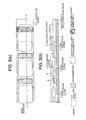
- Fig. 4 is a view showing another example of the structure of the segmented-in-series solid oxide fuel cell, Fig. 4 being a view where the top side surface of the segmented-in-series solid oxide fuel cell, and the back surface side thereof are arranged side by side.
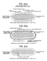
- Figs. 5(a) to 5(c) are sectional views taken on line A - A, line B - B, and line C - C, in Fig. 4 , respectively.
- Fig. 5(a) is the sectional view taken on the line A - A of Fig. 4 , showing a cell positioned at the most downstream end in the direction of a fuel flow.
- an interconnector C, a fuel electrode layer, an electrolyte layer, an air electrode layer, and an interconnector B are sequentially stacked in that order on both the top surface and the back surface of an electrically insulating substrate.
- the interconnector C is disposed on the surface of the electrically insulating substrate, and the fuel electrode layer is disposed on the interconnector C.
- Fig. 5(a) differs in mode from Figs. 2(a), 2(b) , and Figs. 3(a), 3(b) in that the interconnector C is provided on a side of the electrically insulating substrate, adjacent to the fuel electrode layer.
- Fig. 5(b) is the sectional view taken on the line B - B of Fig. 4 , showing a spot where a current-turnaround member is disposed.
- an interconnector C, an interconnector A and an interconnector B are sequentially stacked in that order on the top surface side of the electrically insulating substrate, and a current-turnaround member (a metal layer) is disposed on the uppermost surface thereof.
- a current-turnaround member a metal layer
- an electrolyte layer, and an interconnector B are sequentially stacked in that order on the back surface side of the electrically insulating substrate, and the current-turnaround member (the metal member) is disposed on the uppermost surface side thereof.
- the electrolyte layer, and the current-turnaround member are sequentially stacked on both the side-faces of the electrically insulating substrate (that is, the right and left side-faces of a plurality of cells disposed on either of the top and back surfaces of the electrically insulating substrate)
- Fig. 5(c) is the sectional view taken on the line C - C of Fig. 4 , and as shown in Fig. 5(c) , the electrolyte layer is disposed so as to cover up the outer periphery of the electrically insulating substrate.
- Fig. 6(a) is a sectional view of the segmented-in-series solid oxide fuel cell, taken on line D - D of Fig. 4 , and Fig. 6(a) shows flows of current, fuel, and air, respectively, during operation of the segmented-in-series solid oxide fuel cell. Further, in the lower half part of Fig. 6(a) , the segmented-in-series solid oxide fuel cell is shown as turned upside down as is the case of Fig. 3(b) in relation to Fig. 2(a) .
- Fig. 6(b) is a sectional view corresponding to Fig. 5(a) , showing a current flow during operation of the segmented-in-series solid oxide fuel cell.
- a current flows to the current-turnaround member through the interconnector B, the interconnector A, and the interconnector C in sequence, thence flowing from a spot indicated as "b", in Figs. 6(a), 6(b) , toward a spot indicated as "a” through the current-turnaround member. More specifically, as shown by the curved arrow ( ⁇ ) on either of the right and left sides in Fig.
- the current flows from the interconnector B on the back surface side of the electrically insulating substrate through the current turnaround member to flow to the interconnector B on the top surface side of the electrically insulating substrate.
- electrons flow in the direction opposite to the flow of the current.
- a member indicated as "current-turnaround member (metal)" corresponds to the metal band for use in turning around of current, provided on the outer periphery of the end of the segmented-in-series solid oxide fuel cell, as described in Patent Document 2.
- the current-turnaround structure is made up by the cells positioned at the most downstream end of the electrically insulating substrate, in the direction of the fuel flow. That is, the current turnaround structure is formed by the cells themselves, so that the risk of occurrence of the short circuit, and so forth, encountered in the case of the conventional structure, can be eliminated, and the segmented in series solid oxide fuel cell is rendered safe and highly reliable, being capable of exhibiting stable power generation performance at a high fuel utilization ratio.
- the segmented-in-series solid oxide fuel cell according to the aspects (1) to (4) is a segmented-in-series solid oxide fuel cell comprising a porous electrically insulating substrate having (a) a fuel flow path extending from a fuel feed port to a fuel discharge port, provided therein, and a pair of the top and back surfaces, in parallel with the fuel flow path, together with a pair of side-faces of the porous electrically insulating substrate, in the transverse direction thereof, provided on the exterior thereof, wherein (b) a plurality of solid oxide fuel cells made up by sequentially stacking an interconnector adjacent to a fuel electrode layer, the fuel electrode layer, an electrolyte layer, an air electrode layer, and an interconnector adjacent to the air electrode layer in that order so as to be in parallel with the fuel flow path are disposed at intervals on the pair of the top and back surfaces, respectively, and (c) the plurality of the solid oxide fuel cells are structured such that adjacent solid oxide fuel cells are electrically connected in series with each other through
- Figs. 7(a), 7(b) to Fig. 10 each are a view illustrating features in common with the aspects (1) to (4) of the present invention.
- Fig. 7(a) is a plan view showing the top surface of a portion of the segmented-in-series solid oxide fuel cell including a current-turnaround side thereof
- Fig. 7(b) is a sectional view taken on line A - A of Fig. 7(a) .
- Figs. 7(a), 7(b) to Fig. 10 each are a view illustrating features in common with the aspects (1) to (4) of the present invention.
- Fig. 7(a) is a plan view showing the top surface of a portion of the segmented-in-series solid oxide fuel cell including a current-turnaround side thereof
- Fig. 7(b) is a sectional view taken on line A - A of Fig. 7(a) .
- Figs. 7(a) is a plan view showing the top surface of
- the interconnector C, the fuel electrode layer, the interconnector A, the electrolyte layer, the air electrode layer, and the interconnector B are sequentially stacked in that order on the top surface of the electrically insulating substrate having the fuel flow path extending from the fuel feed port to the fuel discharge port, provided therein.
- a part of the electrically insulating substrate, in Fig. 7(a) , as indicated by legend as "both side ends of an electrically insulating substrate” is a portion of the electrically insulating substrate, for incorporating a current-turnaround structure according to any one of the aspects (1) to (4) of the present invention.
- Fig. 8(a) is a plan view showing the back surface of a portion of the segmented-in-series solid oxide fuel cell, including a current-turnaround side thereof
- Fig. 8(b) is a sectional view taken on line A - A of Fig. 8(a) .
- the interconnector C, the fuel electrode layer, the interconnector A, the electrolyte layer, the air electrode layer, and the interconnector B are sequentially stacked in that order on the back surface of the electrically insulating substrate.
- a part of the electrically insulating substrate, in Fig. 8(a) is a portion of the electrically insulating substrate, for incorporating a current-turnaround structure according to any one of the aspects (1) to (4) of the present invention.
- Figs. 9(a), 9(b) show Figs. 7(a) , 8(a) placed side by side on the same plane of the figure, respectively, and respective spots in Figs. 9(a), and 9(b) , indicated as "both side ends of an electrically insulating substrate", is a portion of the electrically insulating substrate, for incorporating the current-turnaround structure as a feature of any of the aspects (1) to (4) of the present invention.
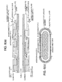
- Fig. 10 shows a sectional view taken on line A - A of Fig. 9(a) , and a sectional view taken on line B - B of Fig. 9(b) .
- the aspects (1) to (4) of the present invention, respectively, have a common sectional shape as shown in Fig. 10 .
- an interconnector C adjacent to a fuel electrode layer, an electrolyte layer, and an interconnector B adjacent to an air electrode layer, making up a pair of solid oxide fuel cells, positioned at the extreme end of the electrically insulating substrate thereof, adjacent to a fuel discharge port, on the pair of the top and back surfaces of the electrically insulating substrate, respectively, are extended to both the right and left side faces in the transverse direction of the electrically insulating substrate, to be disposed thereon, thereby making up a current turnaround structure.
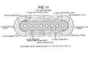
- Fig. 10 and Fig. 11 each are a view illustrating features of the aspect (1) of the present invention.
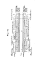
- Fig. 10 is a view combining Fig. 7(a) and
- Fig. 8(b) , and Fig. 11 is a sectional view taken on line C - C in Figs. 9(a), 9(b) , and Fig. 10 , respectively, and enlargedly shown.
- Fig. 10 and Fig. 11 described a current flow during operation of the segmented-in-series solid oxide fuel cell, the flow of electrons is opposite to the flow of the current.
- Fig. 10 as shown in the upper half thereof (corresponding to sectional view taken on line A - A of Fig. 9(a) ), the interconnector C, the fuel electrode layer, the electrolyte layer, the interconnector A, the air electrode layer, and the interconnector B are sequentially stacked in that order on the top surface of the electrically insulating substrate.
- the interconnector C, the fuel electrode layer, the electrolyte layer, the interconnector A, the air electrode layer, and the interconnector B are sequentially stacked in that order on the back surface of the electrically insulating substrate.
- Fig. 11 is a sectional view taken on line C - C in Figs. 9(a), 9(b) , and Fig. 10 , respectively, showing a current turnaround spot at the most downstream end in the direction of the fuel flow, and as shown in Fig. 11 , the interconnector C, the fuel electrode layer, the electrolyte layer, the air electrode layer, and the interconnector B are sequentially disposed in that order on the top surface, and the back surface of the electrically insulating substrate, respectively.
- the interconnector C, the electrolyte layer, and the interconnector B, among those members, are sequentially disposed in that order on both the side-faces of the electrically insulating substrate, that is, the right and left side-faces of a spot of the electrically insulating substrate, where the cell at the most downstream end thereof, in the direction of the fuel flow, is positioned.
- the interconnector C adjacent to the fuel electrode layer, the electrolyte layer and the interconnector B adjacent to the air electrode layer are extended to, and disposed on the right side-face and the left side-face of the electrically insulating substrate, respectively, so as to be integrated together, thereby making up a current-turnaround structure.
- FIG. 11 A current flow in the segmented-in-series solid oxide fuel cell according to the present embodiment is described hereinafter with reference to Figs. 10 , 11 .
- the interconnector C, and the interconnector B are extended toward both the right and left sides of the electrically insulating substrate, and from the back surface side to the top surface side thereof.
- a composite current composed of (a) the current flowing from the cell immediately preceding the current turnaround spot on the back surface side, (b) the current generated by the cell at the current turnaround spot on the back surface side, and (c) the current generated by the cell at the current turnaround spot on the top surface side.
- the composite current flows to the cell immediately preceding the current turnaround spot, on the top surface side via the interconnectors A, C, continuous from the interconnector B on the top surface side.
- the interconnector C adjacent to the fuel electrode layer, the electrolyte layer, and the interconnector B adjacent to the air electrode layer may be disposed on either one side-face of the right and left side-faces of a part of the electrically insulating substrate, where the cell at the most downstream end in the direction of the fuel flow is positioned, however, if the interconnector C adjacent to the fuel electrode layer, the electrolyte layer, and the interconnector B adjacent to the air electrode layer are extended to both the right and left side-faces of the electrically insulating substrate to be then disposed thereon as is the case with the aspect (1) of the present invention, this will enable electrical resistance to be lowered as compared with the case of disposing those members on either one side-face of the right and left side-faces of the electrically insulating substrate, and moreover, the current-turnaround structure will be formed with greater ease.
- Figs. 12(a), 12(b) are sectional views, taken on line C - C, and line D - D of Figs. 9(a), 9(b) , Fig. 10 , respectively.
- the current turnaround member (metal) is no longer required, so that the segmented-in-series solid oxide fuel cell can be simplified in terms of structure. The same can be said of the current turnaround structure according to any one of the aspects (2) to (8) of the present invention.
- the aspect (1) of the present invention since a member such as the metal band, susceptible to oxidation in an oxidizing atmosphere, is not used in the current turnaround part, there is no risk of a short-circuit, and further, since use of dissimilar materials is avoided, a highly reliable current turnaround part can be constructed. In addition, since a power generation area at the most downstream end in the direction of the fuel flow can be enlarged, cell durability can be enhanced. The same can be said of the current turnaround structure according to any one of the aspects (2) to (8) of the present invention.
- an interconnector C adjacent to a fuel electrode layer, the fuel electrode layer, an electrolyte layer, and an interconnector B adjacent to an air electrode layer, making up a pair of solid oxide fuel cells, positioned at the extreme end of the top and back surfaces of the electrically insulating substrate thereof, adjacent to a fuel discharge port, respectively, are extended to both the right and left side faces in the transverse direction of the electrically insulating substrate, to be disposed thereon, thereby making up a current turnaround structure.
- Fig. 13 is a view illustrating features of the aspect (2) of the present invention and a sectional view showing the current turnaround spot at the most downstream end in the direction of the fuel flow.
- the interconnector C, the fuel electrode layer, the electrolyte layer, the air electrode layer and interconnector B are sequentially disposed on the top and back surfaces of the electrically insulating substrate.
- the interconnector C adjacent to the fuel electrode layer, the fuel electrode layer, the electrolyte layer, and the interconnector B adjacent to the air electrode layer are sequentially disposed in this order on both side faces of the electrically insulating substrate, namely, on both the right and left side-faces of the electrically insulating substrate where the cell at the extreme end in the direction of fuel flow is positioned.
- the interconnector C adjacent to the fuel electrode layer, the fuel electrode layer, the electrolyte layer and the interconnector B adjacent to the air electrode layer are extended to, and disposed on the right side-face and the left side-face of the electrically insulating substrate, respectively, so as to be integrated together, thereby making up a current-turnaround structure.
- the interconnector C, the fuel electrode layer, the electrolyte layer, and the interconnector B are shared by the cell positioned at the most downstream end in the direction of the fuel flow, on the top surface side of the electrically insulating substrate, and the cell positioned at the most downstream end in the direction of the fuel flow, on the back surface side thereof.
- a current flow in the current-turnaround structure according to the present embodiment is the same as that described under the heading (Current flow in the current turnaround structure) in connection with (An embodiment of a segmented in series solid oxide fuel cell according to the aspect (1) of the present invention).
- an interconnector C adjacent to a fuel electrode layer, an electrolyte layer, an air electrode layer, and an interconnector B adjacent to the air electrode layer, making up a pair of solid oxide fuel cells, positioned at the extreme end of the top and back surfaces of the electrically insulating substrate thereof, adjacent to a fuel discharge port, respectively, are extended to both the right and left side faces in the transverse direction of the electrically insulating substrate, to be disposed thereon, thereby making up a current turnaround structure.
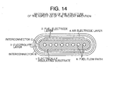
- Fig. 14 is a view illustrating features of the aspect (3) of the present invention and a sectional view showing the current turnaround spot at the most downstream end in the direction of the fuel flow.
- the interconnector C, the fuel electrode layer, the electrolyte layer, the air electrode layer and the interconnector B are sequentially disposed on the top and back surfaces of the electrically insulating substrate.
- the interconnector C, the electrolyte layer, the air electrode layer and the interconnector B are sequentially disposed in this order on both side faces of the electrically insulating substrate, namely, on both the right and left side-faces of the electrically insulating substrate where the cell at the extreme end in the direction of fuel flow is positioned.
- the interconnector C adjacent to the fuel electrode layer, the fuel electrode layer, the electrolyte layer and the interconnector B adjacent to the air electrode layer are extended to, and disposed on the right side-face and the left side-face of the electrically insulating substrate, respectively, so as to be integrated together, thereby making up a current-turnaround structure.
- the interconnector C, the electrolyte layer, the air electrode layer, and the interconnector B are shared by the cell positioned at the most downstream end in the direction of the fuel flow, on the top surface side of the electrically insulating substrate, and the cell positioned at the most downstream end in the direction of the fuel flow, on the back surface side thereof.
- a current flow in the current-turnaround structure according to the present embodiment is the same as that described under the heading (Current flow in the current turnaround structure) in connection with (An embodiment of a segmented-in-series solid oxide fuel cell according to the aspect (1) of the present invention).
- an interconnector C adjacent to a fuel electrode layer, the fuel electrode layer, an electrolyte layer, an air electrode layer, and an interconnector B adjacent to the air electrode layer, making up a pair of solid oxide fuel cells, positioned at the extreme end of the top and back surfaces of the electrically insulating substrate thereof, adjacent to a fuel discharge port, respectively, are extended to both the right and left side faces in the transverse direction of the electrically insulating substrate, to be disposed thereon, thereby making up a current turnaround structure.
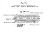
- Fig. 15 is a view illustrating features of the aspect (4) of the present invention and a sectional view showing the current turnaround spot at the most downstream end in the direction of the fuel flow.
- the interconnector C, the fuel electrode layer, the electrolyte layer, the air electrode layer and the interconnector B are sequentially disposed on the top and back surfaces of the electrically insulating substrate.
- the interconnector C, the fuel electrode layer, the electrolyte layer, the air electrode layer and the interconnector B are sequentially disposed in this order on both side faces of the electrically insulating substrate, namely, on both the right and left side-faces of the electrically insulating substrate where the cell at the extreme end in the direction of fuel flow is positioned.
- the interconnector C adjacent to the fuel electrode layer, the fuel electrode layer, the electrolyte layer, the air electrode layer and the interconnector B adjacent to the air electrode layer are extended to, and disposed on the right side-face and the left side-face of the electrically insulating substrate, respectively, so as to be integrated together, thereby making up a shared current-turnaround structure.
- the interconnector C is disposed on the right side-face and the left side-face of a part of the electrically insulating substrate, positioned at the most downstream end in the direction of the fuel flow in addition to both the top surface and the back surface of the electrically insulating substrate, that is, on the entire peripheral surface of the electrically insulating substrate, the fuel electrode layer is disposed on the entire peripheral surface of the interconnector C, the electrolyte layer is disposed on the entire peripheral surface of the fuel electrode layer, the air electrode layer is disposed on the entire peripheral surface of the electrolyte layer, and further, the interconnector B is disposed on the entire peripheral surface of the air electrode layer, thereby completing a structure wherein one cell, the interconnector C adjacent to the fuel electrode layer, and the interconnector B adjacent to the air electrode layer are disposed on the entire peripheral surface of the part of the electrically insulating substrate, positioned at the most downstream end in the direction of the fuel flow.
- a current flowing from the cell immediately preceding the current turnaround spot at the most downstream end in the direction of the fuel flow via the interconnector A proceeds to the interconnector C at the current turnaround spot, flowing thence to the one cell before flowing to the interconnector B at the current turnaround spot. That is, one cell having (the fuel electrode layer - the electrolyte layer the air electrode layer) is made up between the interconnector C, and the interconnector B, and to put it plainly, the one cell acts as a cell for power generation, and as current-turnaround means.
- the segmented-in-series solid oxide fuel cell is structured as above, if a total length of a plurality of cells (effective cells) disposed on the electrically insulating substrate, in the direction of the fuel flow, is constant, the cells in a current turnaround part of the electrically insulating substrate will have, in effect, an effective area at least twice as large. Accordingly, current density of the cells in the current turnaround part can be effectively lowered than that of other cells, thereby enabling potential drop to be checked.
- Figs. 10 , 15 there is shown the current flow in the current turnaround structure.
- the current during operation flows from the cell immediately preceding the current turnaround spot at the most downstream end in the direction of the fuel flow to the interconnector C at the current turnaround spot via the interconnector A to subsequently flow to the cell in the current turnaround spot before flowing to the interconnector B.
- Table 1 shows various types of the current turnaround structure according to any one of aspects (1) to (4) of the present invention.
- patterns 1 to 4 correspond to the respective current turnaround structures according to the aspects (1) to (4) of the present invention.
- Table 1
- Types of the current turnaround structure in which fuel is flowed pattern 1 pattern 2 pattern 3 pattern 4 interconnector B adjacent to air electrode layer ⁇ ⁇ ⁇ ⁇ air electrode layer X X ⁇ ⁇ electrolyte layer ⁇ ⁇ ⁇ ⁇ fuel electrode layer X ⁇ X ⁇ interconnector C adjacent to fuel electrode layer ⁇ ⁇ ⁇ ⁇ electrically insulator substrate - - - - (Remarks) ⁇ : a current is turned around, X: a current is not turned around
- the segmented-in-series solid oxide fuel cell is a segmented-in-series solid oxide fuel cell comprising a porous electrically insulating substrate having (a) an air flow path extending from an air feed port to an air discharge port, provided therein, and a pair of the top and back surfaces, in parallel with the air flow path, together with a pair of side-faces of the porous electrically insulating substrate, in the transverse direction thereof, provided on the exterior thereof; wherein (b) a plurality of solid oxide fuel cells made up by sequentially stacking an interconnector adjacent to an air electrode layer, the air electrode layer, an electrolyte layer, a fuel electrode layer, and an interconnector adjacent to the fuel electrode layer in that order so as to be in parallel with the air flow path are disposed at intervals on the pair of the top and back surfaces, respectively; and (c) the plurality of the solid oxide fuel cells are structured such that adjacent solid oxide fuel cells are electrically connected in series with each other through the intermediary
- Figs. 16 , 17 each are a view for describing the features in common with the aspects (5) to (8) of the present invention.
- Figs. 16 , 17 correspond to Figs. 10 , 11 , respectively, the latter being the figures referred to in describing the group of the aspects (1) to (4) of the present invention.
- the interconnector B, the air electrode layer, the electrolyte layer, the fuel electrode layer, and the interconnector C are sequentially disposed in that order on both the top surface, and the back surface of the electrically insulating substrate in which the air flow path T extending from the air feed port to the air discharge port.
- the electrically insulating substrate according to any one of the aspects (5) to (8) of the present invention differs from the electrically insulating substrate according to any one of the aspects (1) to (4) of the present invention in that the electrically insulating substrate is an electrically insulating substrate having an air flow path provided therein, and that the interconnector B, the air electrode layer, the electrolyte layer, the fuel electrode layer, and the interconnector C are sequentially disposed in that order on both the top and the back surfaces of the electrically insulating substrate.
- a part of the segmented-in-series solid oxide fuel cell indicated as "the cell at the extreme end in the direction of the air flow" in Fig. 10 , is a part of the segmented-in-series solid oxide fuel cell, for incorporating the current turnaround structure according to any one of the aspects (5) to (8) of the present invention,.
- the electrolyte layer, and the interconnector A are disposed on an upper surface of the air electrode layer provided on the back surface side of the electrically insulating substrate.
- the interconnector B of the cell at the extreme end in the direction of the air flow is electrically connected with the interconnector C of the cell immediately preceding the cell at the extreme end in the direction of the air flow by means of the interconnector A.
- an interconnector B adjacent to an air electrode layer, an electrolyte layer, and an interconnector C adjacent to a fuel electrode layer, making up a pair of solid oxide fuel cells, positioned at the extreme end of the top and back surfaces of the electrically insulating substrate thereof, adjacent to an air discharge port, respectively, are extended to both the right and left side faces in the transverse direction of the electrically insulating substrate, to be disposed thereon, thereby making up a current turnaround structure.
- Fig. 16 and Fig. 17 are a view illustrating features of the aspect (5) of the present invention and showing a current flow during operation of the segmented-in-series solid oxide fuel cell.
- the interconnector B, the air electrode layer, the electrolyte layer, the fuel electrode layer and the interconnector C are sequentially disposed on the top surface of the electrically insulating substrate.
- the interconnector B, the air electrode layer, the electrolyte layer, the fuel electrode layer and the interconnector C are sequentially disposed on the back surface of the electrically insulating substrate.
- Fig. 17 is a view illustrating the current turnaround structure serving as features of the aspect (5) of the present invention. and corresponds to the sectional view taken on line C - C of Fig. 16 .
- the interconnector B, the air electrode layer, the electrolyte layer, the fuel electrode layer and the interconnector C are sequentially disposed on the top and back surfaces of the electrically insulating substrate.
- the interconnector B, the electrolyte layer and the interconnector C are sequentially disposed in this order on both side faces of the electrically insulating substrate, namely, on both the right and left side-faces of the electrically insulating substrate where the cell at the extreme end in the direction of fuel flow is positioned.
- the interconnector B adjacent to the air electrode layer, the electrolyte layer and the interconnector C adjacent to the fuel electrode layer are extended to, and disposed on the right side-face and the left side-face of the electrically insulating substrate of the solid oxide fuel cells, respectively, so as to be integrated together, thereby making up a current-turnaround structure.
- FIG. 16 A current flow in the current turnaround structure according to the aspect (5) of present invention is described hereinafter with reference to Figs. 16 , and 17 .
- the interconnector B, and the interconnector C are extended from the back surface side of the electrically insulating substrate to the top surface thereof, and toward both the right and left sides of the electrically insulating substrate, in the transverse direction thereof.
- flowing to the interconnector C, on the back surface side is a composite current composed of (a) the current flowing from the cell immediately preceding the current turnaround spot, on the top surface side, (b) the current generated by the cell at the current turnaround spot on the top surface side, and (c) the current generated by the cell at the current turnaround spot, on the back surface side. Then, the composite current flows to the cell immediately preceding the current turnaround spot, on the top surface side via the interconnector A, and the interconnector C, continuous from the interconnector B.
- the interconnector B adjacent to the air electrode layer, the electrolyte layer, and the interconnector C adjacent to the fuel electrode layer are disposed on one side-face of the right and left side-faces of the electrically insulating substrate, however, if those members are extended to the right and left side-faces of the electrically insulating substrate to be disposed thereon as is the case with the aspect (5) of the present invention, this will enable electrical resistance to be lowered and further, those layers can be formed on the top and back surfaces as well as the right and left side-faces by use of the same kind of material, so that formation of the structure will be easier as compared with the case of disposing those members on the one side-face of the right and left side-faces of the electrically insulating substrate while extended thereto.
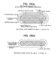
- Figs. 18(a), and 18(b) are sectional views taken on line C - C, and D - D of Fig. 16 , respectively.
- an interconnector B adjacent to an air electrode layer, an electrolyte layer, a fuel electrode layer, and an interconnector C adjacent to the fuel electrode layer, making up a pair of solid oxide fuel cells, positioned at the extreme end of the top and back surfaces of the electrically insulating substrate thereof, adjacent to an air discharge port, respectively, are extended to both the right and left side faces in the transverse direction of the electrically insulating substrate, to be disposed thereon, thereby making up a current turnaround structure.
- Fig. 19 is a view illustrating features of the aspect (6) of the present invention and a sectional view showing the current turnaround spot at the most downstream end in the direction of air flow.
- the interconnector B, the air electrode layer, the electrolyte layer, the fuel electrode layer, and the interconnector C are sequentially disposed on the top and back surfaces of the electrically insulating substrate.
- the interconnector B, the air electrode layer, the electrolyte layer, the fuel electrode layer, and the interconnector C are sequentially disposed in this order on both side faces of the electrically insulating substrate, namely, on both the right and left side-faces of the electrically insulating substrate where the cell at the extreme end in the direction of air flow is positioned.
- the interconnector B adjacent to the air electrode layer, the air electrode layer, the electrolyte layer and the interconnector C adjacent to the fuel electrode layer are extended to, and disposed on the right side-face and the left side-face of the electrically insulating substrate, respectively, so as to be integrated together, thereby making up a shared current-turnaround structure.
- a current flow in the current turnaround structure during operation of the fuel cell is the same as described in the embodiment according to the aspect (5) of the present invention.
- an interconnector B adjacent to an air electrode layer, the air electrode layer, an electrolyte layer, and an interconnector C adjacent to a fuel electrode layer, making up a pair of solid oxide fuel cells, positioned at the extreme end of the top and back surfaces of the electrically insulating substrate thereof, adjacent to an air discharge port, respectively, are extended to both the right and left side faces in the transverse direction of the electrically insulating substrate, to be disposed thereon, thereby making up a current turnaround structure.
- Fig. 20 is a view illustrating features of the aspect (7) of the present invention and a sectional view showing the current turnaround spot at the most downstream end in the direction of air flow.
- the interconnector B, the air electrode layer, the electrolyte layer, the fuel electrode layer, and the interconnector C are sequentially disposed on the top and back surfaces of the electrically insulating substrate.
- the interconnector B, the electrolyte layer, the fuel electrode layer, and the interconnector C are sequentially disposed in this order on both side faces of the electrically insulating substrate, namely, on both the right and left side-faces of the electrically insulating substrate where the cell at the extreme end in the direction of air flow is positioned.
- the interconnector B adjacent to the air electrode layer, the electrolyte layer, the fuel electrode layer and the interconnector C adjacent to the fuel electrode layer are extended to, and disposed on the right side-face and the left side-face of the electrically insulating substrate, respectively, so as to be integrated together, thereby making up a shared current-turnaround structure.
- a current flow in the current turnaround structure during operation of the fuel cell is the same as described in the embodiment according to the aspect (5) of the present invention.
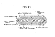
- an interconnector B adjacent to an air electrode layer, the air electrode layer, an electrolyte layer, a fuel electrode layer, and an interconnector C adjacent to the fuel electrode layer, making up a pair of solid oxide fuel cells, positioned at the extreme end of the top and back surfaces of the electrically insulating substrate thereof, adjacent to an air discharge port, respectively, are extended to both the right and left side faces in the transverse direction of the electrically insulating substrate, to be disposed thereon, thereby making up a current turnaround structure.
- Fig. 21 is a view illustrating features of the aspect (8) of the present invention and a sectional view showing the current turnaround spot at the most downstream end in the direction of air flow.
- the interconnector B, the air electrode layer, the electrolyte layer, the fuel electrode layer, and the interconnector C are sequentially disposed on the top and back surfaces of the electrically insulating substrate.
- the interconnector B, the air electrode layer, the electrolyte layer, the fuel electrode layer, and the interconnector C are also sequentially disposed in this order on both the right and left side-faces of the electrically insulating substrate where the cell at the extreme end in the direction of air flow is positioned.
- the interconnector B adjacent to the air electrode layer, the air electrode layer, the electrolyte layer, the fuel electrode layer and the interconnector C adjacent to the fuel electrode layer are extended to, and disposed on the right side-face and the left side-face of the electrically insulating substrate, respectively, so as to be integrated together, thereby making up a shared current-turnaround structure.
- the interconnector B is disposed on the right side-face and the left side-face of a part of the electrically insulating substrate, positioned at the most downstream end in the direction of the air flow in addition to both the top side surface and the back surface side of the electrically insulating substrate, that is, on the entire peripheral surface of the electrically insulating substrate, the air electrode layer is disposed on the entire peripheral surface of the interconnector B, the electrolyte layer is disposed on the entire peripheral surface of the air electrode layer, the fuel electrode layer is disposed on the entire peripheral surface of the electrolyte layer, and further, the interconnector C is disposed on the entire peripheral surface of the fuel electrode layer, thereby completing a structure wherein one cell, the interconnector B adjacent to the air electrode layer, and the interconnector C adjacent to the fuel electrode layer are disposed on the entire peripheral surface of the part of the electrically insulating substrate, at the most downstream end in the direction of the air flow.
- the fuel electrode layer - the electrolyte layer - the air electrode layer is made up between the interconnector B, and the interconnector C, and the one cell acts as a cell for power generation, and as current-turnaround means.
- the cell area of a current turnaround part is enlarged, so that the current density of the cell can be effectively lowered than that of other cells, thereby enabling potential drop to be checked.
- a current flow in the current turnaround structure With the segmented-in-series solid oxide fuel cell having the current turnaround structure according to the aspect (8) of the present invention, a current during operation flows from the cell immediately preceding the current turnaround spot at the most downstream end in the direction of the air flow to the interconnector C of a current turnaround spot via the interconnector A to thence flow to the cell in the current turnaround spot before flowing to the interconnector B.
- Table 2 shows various types of the current turnaround structure according to any one of aspects (5) to (8) of the present invention.
- patterns 5 to 8 each correspond to the current turnaround structure according to any one of aspects (5) to (8) of the present invention.
- Types of the current turnaround structure in which air (an oxidizer) is flowed pattern 5 pattern 6 pattern 7 pattern 8 interconnector.
- a sample of the segmented-in-series solid oxide fuel cell according to the present invention, and a sample of the segmented-in-series solid oxide fuel cell of the conventional structure were prepared and an internal stress was measured on each of the samples.
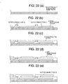
- Figs. 22(a) to 22(e) each are a partially cutaway view showing process steps from fabrication of a porous electrically insulating substrate up to formation of a structure shown in Figs. 23 , 24 , respectively.
- NiO, MgO, and Y 2 O 3 are prepared for the constituent material of a porous electrically insulating substrate.
- Those raw material powders were weighed so as to be at 15 mol%, 72 mol%, and 13 mol%, respectively, and carbon powders, together with cellulose, to serve as a pore-forming material, were added thereto, adding further water thereto before mixing in a ball mill.
- An organic solvent, an organic binder, a dispersant, and an anti-foam agent were added to powders obtained by mixing NiO with YSZ at a mass ratio of 3 : 2 to be mixed in a ball mill, thereby preparing a slurry.
- the slurry was formed into a sheet on a film (a release sheet) by the doctor blade method to be subsequently dried to thereby form an interconnector C.
- the constituent material of the interconnector C may be the same material as used for the fuel electrode layer, as previously described, and in this case, use was made of a material similar to that for the fuel electrode layer, composed of NiO and YSZ although a mass ratio of NiO : YSZ differs from that for the fuel electrode layer.
- An organic solvent, an organic binder, a dispersant, and an anti-foam agent were added to powders obtained by mixing NiO with YSZ at a mass ratio of 2 : 3 to be mixed in a ball mill, thereby preparing a slurry.
- the slurry was formed into a sheet on the top surface of the interconnector C by the doctor blade method to be subsequently dried to thereby execute laminated molding of a fuel electrode layer.
- An organic solvent, an organic binder, a dispersant, and an anti-foam agent were added to lanthanum chromate (La 0.8 Sr 0.2 CrO 3 ) powders to be mixed in a ball mill to thereby prepare a slurry, and the slurry was applied by the screen printing method to a predetermined position of the fuel electrode layer as sheet-formed on a film formed in the step of (3. formation of a fuel electrode layer) to be dried, thereby execute laminated molding of an interconnector A
- the interconnector C, the fuel electrode layer, and the interconnector A, in as-laminated state, were peeled off from the film with the interconnector C, the fuel electrode layer, and the interconnector A, laminated thereon, to be glued onto the electrically insulating substrate, whereupon the interconnector C, the fuel electrode layer, and the interconnector A were formed on the top of the electrically insulating substrate.
- Work in process after the process steps as above was fired at 1150°C. This state is shown in Fig. 22(b) .
- An organic solvent, an organic binder, a dispersant, and an anti-foam agent were added to a perovskite oxide [(La 0.6 Sro 0.4 ) Co 0.2 Fe 0.8 O 3 ]powders to be mixed in a ball mill for 20 hours to thereby prepare a slurry.
- the slurry was applied by the screen-printing method to the surface of a film of the electrolyte layer obtained in the step ⁇ 5. Formation of an electrolyte layer> as above to be subsequently fired at 1150°C. This state is shown in Fig. 22(d) .
- an AgPd paste to serve as an interconnector B was applied between the air electrode layer, and the interconnector A to thereby connect both members with each other.
- the paste was also applied to the outer peripheral surfaces on the side of the electrically insulating substrate, at the most downstream end thereof, in the direction of the fuel flow. This state is shown in Fig. 22(e) .
- the sample of the segmented-in-series solid oxide fuel cell wherein six cells were disposed on the top surface side of the electrically insulating substrate, and six cells were disposed the back surface side thereof.
- the cell at the rightmost end of the electrically insulating substrate, in the figure, that is, the most downstream end thereof, in the direction of the fuel flow, on the top surface side thereof are joined with the cell at the rightmost end of the electrically insulating substrate, that is, the most downstream end thereof, in the direction of the fuel flow, on the back surface side thereof, thereby making up one cell, so that the number of the cells will be eleven in total.
- the internal stress thereof was measured by the X-ray stress measuring method. This measurement was taken in accordance with the method described in " Lecture Summaries of the 15th SOFC Study Forum (held at Science Technology Hall, Tokyo, during Dec. 5 to 6, 2006), pp. 28 to 34 ". The same applies to measurement under the heading (Internal stress of the segmented-in-series solid oxide fuel cell according to the present invention) described later in the present sp ecification.
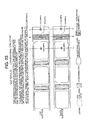
- Table 3 and Fig. 23 each show test results.
- Table 3 and Fig. 23 computation results as well are indicated besides the test results, and in Fig. 23 , the computation results are shown in parentheses.
- the internal stress thereof was measured by the X-ray stress measuring method.
- Table 4, and Fig. 24 each show test results. In Table 4, computation results as well are shown besides the test results.
- the interconnector high in internal stress was not disposed at the most downstream end of the electrically insulating substrate, in the direction of the fuel flow. This enables cracking of the electrically insulating substrate to be avoided, which is advantageous from the standpoint of durability over the long term, so that it is possible to solve the problem including cracking at the end of the electrically insulating substrate in the conventional structure.
- Table 4 spot along line A - A spot along lineB-B computation results top surface 400 MPa 500 MPa back surface 400 MPa 300 MPa test results electrolyte layer portion 378.6 MPa 323.0 MPa
Landscapes
- Life Sciences & Earth Sciences (AREA)
- Engineering & Computer Science (AREA)
- Manufacturing & Machinery (AREA)
- Sustainable Development (AREA)
- Sustainable Energy (AREA)
- Chemical & Material Sciences (AREA)
- Chemical Kinetics & Catalysis (AREA)
- Electrochemistry (AREA)
- General Chemical & Material Sciences (AREA)
- Fuel Cell (AREA)
Abstract
Description
- The present invention relates to a segmented-in-series solid oxide fuel cell, and more specifically, to a segmented-in-series solid oxide fuel cell comprising a porous electrically insulating substrate having a fuel flow path, provided therein, and a plurality of solid oxide fuel cells disposed in a segmented-in-series fashion, provided on a pair of surfaces of the porous electrically insulating substrate, opposing each other, and a segmented-in-series solid oxide fuel cell comprising a porous electrically insulating substrate having an air flow path, provided therein, and a plurality of solid oxide fuel cells disposed in a segmented-in-series fashion, provided on a pair of surfaces of the porous electrically insulating substrate, opposing each other. The solid oxide fuel cell is hereinafter termed merely as "the cells" for short as appropriate.
- A segmented-in-series solid oxide fuel cell is a fuel cell of a type wherein a plurality of cells disposed in a segmented-in-series fashion are made up by disposing a fuel electrode layer, and an air electrode layer in such a way as to cause an electrolytic material composed of an electrolyte to be sandwiched therebetween while disposing an interconnector on a side of the cell, adjacent to the fuel electrode layer, and an interconnector on a side of the cell, adjacent to the air electrode layer, as appropriate. The segmented-in-series oxide fuel type cell includes a cylindrical type as described in
JP Hei 10 (1998) - 3932 - A JP 2006 -19059 - A - When the solid oxide fuel cell is operated, fuel is circulated to the fuel electrode layer of the cell, an oxidizer gas (hereinafter typically referred to as "air" where appropriate), such as air, oxygen, and so forth, is flowed to the air electrode layer thereof, and the respective electrodes are connected to an external load, whereupon electric power is obtained. However, with the use of a single cell of one unit only, a voltage only in a range of about 0.7 to 0.8V at most can be obtained, there is the need for electrically connecting a plurality of single cells (the cells) in series with each other in order to obtain electric power for practical use.
- The segmented-in-series solid oxide fuel cell of the hollow flat type is made up by disposing the plurality of the cells on the respective flat surfaces of a porous electrically insulating substrate, in a hollow flat sectional shape, that is, an electrically insulating substrate, more specifically, on each of a pair of the surfaces thereof, opposing each other, and by electrically connecting adjacent cells with each other via an interconnector. A hollow part of the electrically insulating substrate in the hollow flat sectional shape is formed inside the substrate, and the hollow part normally serves as a gas flow path for flowing fuel or air from a port at one end thereof toward a port at the other end thereof (as a fuel flow path in the case of flowing fuel, and as an air flow path in the case of flowing air).
- With the segmented-in-series solid oxide fuel cell, cell layout has high flexibility, and a current output position can be optionally set, however, in practical application, the current output position is set at the same end of the electrically insulating substrate. In such a case, a current at the time of operation is caused to flow from an end of the electrically insulating substrate, in the direction of a lineup of the plurality of the cells disposed on the top surface of the electrically insulating substrate, and to an end of one of the plurality of the cells disposed on the back surface of the electrically insulating substrate (that is, to an end of the electrically insulating substrate, on the back surface side thereof) in the direction opposite from the direction of a current flow on the top surface side.
-
Figs. 1(a) to 1(c) are views showing an example of the structure of a segmented-in-series solid oxide fuel cell of the hollow flat type, in whichFig. 1(a) is a perspective view, andFig. 1(b) is a plan view. A plurality ofcells 5, each having a three-layered structure comprised of a fuel electrode layer, an electrolyte layer, and an air electrode layer, are disposed on both an upper surface and an underside surface of an electricallyinsulating substrate 1 in a hollow flat sectional shape, namely, both the top surface, and the back surface thereof. The segmented-in-series solid oxide fuel cell is made up by electrically connecting the adjacent cells in series with each other through the intermediary of an interconnector. - At the time of operation of the segmented in series solid oxide fuel cell of the hollow flat type, fuel is flowed through a fuel flow path S extending from a fuel feed port to a fuel discharge port, provided in the electrically insulating
substrate 1, in parallel with the lineup of thecells 5, as indicated by the arrow (→) inFig. 1(a) . The number of the fuel flow paths S is not limited to one, and a plurality thereof may be provided, andFig. 1(c) illustrates an example where eight pieces of the fuel flow paths S are provided. Further, the electricallyinsulating substrate 1, in a mode of the hollow flat type shown inFig. 1(a) , is rectangular in cross sectional shape (in sectional shape perpendicular to the direction of the lineup of the plurality of the cells), but the cross sectional shape of the electricallyinsulating substrate 1 is not limited thereto, and may be square, elliptical, and so forth, as appropriate. - In
Fig. 1(a) , there is shown a current flow during operation in a mode where current is turned around at the end of the electrically insulatingsubstrate 1, in the direction of a fuel flow, that is, at the fuel discharge port. Referring toFig. 1(a) , the segmented-in-series solid oxide fuel cell is structured such that a current is caused to flow from a proximal end of the electricallyinsulating substrate 1 to an end on the opposite side thereof, that is, from thecell 5 disposed at a distal end on the back surface of the electricallyinsulating substrate 1 to thecell 5 disposed at a distal end on the top surface thereof. Now, a state in which a current flowing toward one end of the electrically insulating substrate, on one of the surfaces thereof, continues to flow to the other surface thereof, at the one end, and subsequently, the current flows toward the other end of the electrically insulating substrate is hereinafter referred to as "a current is turned around" in the present specification. A structure for causing this state is called a current-turnaround structure where appropriate. - With reference to the present specification, and accompanying drawings, terms the top surface, and the back surface are used in referring to both the top and back surfaces of the electrically insulating substrate, or both surfaces of the top surface, and the back surface thereof, and so forth, however, it is to be understood that those terms are used just for the sake of convenience in explanation, and in, for example, the perspective view of
Fig. 1(a) , an upper surface, that is, a visible surface is referred to as the top surface, whereas an underside surface, that is, an invisible surface is referred to as the back surface, and therefore, if the electrically insulating substrate is turned upside down, the back surface inFig. 1(a) will be the top surface while the top surface inFig. 1(a) will be the back surface. - With the segmented-in-series solid oxide fuel cell described in
Patent Document 1, a plurality ofcells 25 are disposed on an electricallyinsulating substrate 28 such that thecells 25 are electrically connected in series with each other, and a current inlet and a current outlet are positioned at respective ends of the electrically insulatingsubstrate 28, as shown inFig. 25 . In this case, there is the need for drawing a lead wire for use in outputting current through the electrically insulatingsubstrate 28 up to a plus terminal at the right end thereof, so that there are needs for various design ideas such as a measure for preventing the lead wire from being disengaged, and so forth. - Further, with the segmented-in-series solid oxide fuel cell as described in
Patent Document 2, use is made of a metal band to be used in turning around current, provided on the outer periphery of an end of an electrically insulating substrate, as shown inFig. 26 . However, in the case of the segmented-in-series solid oxide fuel cell of such a type as to use the metal band, there is a concern about reliability of the metal band in terms of breakage of the metal band, and so forth, attributable to oxidation thereof, due to a thermal cycle caused by repetition in operation / stoppage of the segmented-in-series solid oxide fuel cell, and because the metal band is exposed to an air flow path side of the segmented-in-series solid oxide fuel cell, in an oxidizing atmosphere, there is also a concern about the risk of the metal band being disengaged to come into contact with an external part, thereby developing a short-circuit. - The present invention has been developed in order to solve problems described as above with the segmented in series solid oxide fuel cell, and it is an object of the present invention to provide a segmented-in-series solid oxide fuel cell having a safe and highly reliable structure capable of exhibiting stable power generation performance at a high fuel utilization ratio, serving as means for turning around current at an end of the segmented-in-series solid oxide fuel cell, on a current turnaround side thereof.
- In accordance with an aspect (1) of the present invention, there is provided a segmented-in-series solid oxide fuel cell comprising a porous electrically insulating substrate having (a) a fuel flow path extending from a fuel feed port to a fuel discharge port, provided therein, and a pair of the top and back surfaces, in parallel with the fuel flow path, together with a pair of side-faces of the porous electrically insulating substrate, in the transverse direction thereof, provided on the exterior thereof, wherein (b) a plurality of solid oxide fuel cells made up by sequentially stacking an interconnector adjacent to a fuel electrode layer, the fuel electrode layer, an electrolyte layer, an air electrode layer, and an interconnector adjacent to the air electrode layer in that order so as to be in parallel with the fuel flow path are disposed at intervals on the pair of the top and back surfaces, respectively, and (c) the plurality of the solid oxide fuel cells are structured such that adjacent solid oxide fuel cells are electrically connected in series with each other through the intermediary of the respective interconnectors.
- Further, (d) a current turnaround structure is made up by extending the interconnector adjacent to the fuel electrode layer, the electrolyte layer, and the interconnector adjacent to the air electrode layer, making up a pair of the solid oxide fuel cells, positioned at the extreme end of the electrically insulating substrate, in the longitudinal direction thereof, adjacent to the fuel discharge port, on the pair of the top and back surfaces of the electrically insulating substrate, respectively, to both the side faces of the electrically insulating substrate, in the transverse direction thereof, to be disposed thereon.
- In accordance with an aspect (2) of the present invention, there is provided a segmented-in-series solid oxide fuel cell comprising a porous electrically insulating substrate having (a) a fuel flow path extending from a fuel feed port to a fuel discharge port, provided therein, and a pair of the top and back surfaces, in parallel with the fuel flow path, together with a pair of side-faces of the porous electrically insulating substrate, in the transverse direction thereof, provided on the exterior thereof, wherein (b) a plurality of solid oxide fuel cells made up by sequentially stacking an interconnector adjacent to a fuel electrode layer, the fuel electrode layer, an electrolyte layer, an air electrode layer, and an interconnector adjacent to the air electrode layer in that order so as to be in parallel with the fuel flow path are disposed at intervals on the pair of the top and back surfaces, respectively, and (c) the plurality of the solid oxide fuel cells are structured such that adjacent solid oxide fuel cells are electrically connected in series with each other through the intermediary of the respective interconnectors. Further, (d) a current turnaround structure is made up by extending the interconnector adjacent to the fuel electrode layer, the fuel electrode layer, the electrolyte layer, and the interconnector adjacent to the air electrode layer, making up a pair of the solid oxide fuel cells, positioned at the extreme end of the electrically insulating substrate, in the longitudinal direction thereof, adjacent to the fuel discharge port, on the pair of the top and back surfaces of the electrically insulating substrate, respectively, to both the side faces in the transverse direction of the electrically insulating substrate to be disposed thereon.
- In accordance with an aspect (3) of the present invention, there is provided a segmented-in-series solid oxide fuel cell comprising a porous electrically insulating substrate having (a) a fuel flow path extending from a fuel feed port to a fuel discharge port, provided therein, and a pair of the top and back surfaces, in parallel with the fuel flow path, together with a pair of side-faces of the porous electrically insulating substrate, in the transverse direction thereof, provided on the exterior thereof, wherein (b) a plurality of solid oxide fuel cells made up by sequentially stacking an interconnector adjacent to a fuel electrode layer, the fuel electrode layer, an electrolyte layer, an air electrode layer, and an interconnector adjacent to the air electrode layer in that order so as to be in parallel with the fuel flow path are disposed at intervals on the pair of the top and back surfaces, respectively, and (c) the plurality of the solid oxide fuel cells are structured such that adjacent solid oxide fuel cells are electrically connected in series with each other through the intermediary of the respective interconnectors. Further, (d) a current turnaround structure is made up by extending the interconnector adjacent to the fuel electrode layer, the electrolyte layer, the air electrode layer, and the interconnector adjacent to the air electrode layer, making up a pair of the solid oxide fuel cells, positioned at the extreme end of the electrically insulating substrate, in the longitudinal direction thereof, adjacent to the fuel discharge port, on the pair of the top and back surfaces of the electrically insulating substrate, respectively, to both the side faces in the transverse direction of the electrically insulating substrate to be disposed thereon.
- In accordance with an aspect (4) of the present invention, there is provided a segmented-in-series solid oxide fuel cell comprising a porous electrically insulating substrate having (a) a fuel flow path extending from a fuel feed port to a fuel discharge port, provided therein, and a pair of the top and back surfaces, in parallel with the fuel flow path, together with a pair of side-faces of the porous electrically insulating substrate, in the transverse direction thereof, provided on the exterior thereof, wherein (b) a plurality of solid oxide fuel cells made up by sequentially stacking an interconnector adjacent to a fuel electrode layer, the fuel electrode layer, an electrolyte layer, and an air electrode layer, and an interconnector adjacent to the air electrode layer in that order so as to be in parallel with the fuel flow path are disposed at intervals on the pair of the top and back surfaces, respectively, and (c) the plurality of the solid oxide fuel cells are structured such that adjacent solid oxide fuel cells are electrically connected in series with each other through the intermediary of the respective interconnectors. Further, (d) a current turnaround structure is made up by extending the interconnector adjacent to the fuel electrode layer, the fuel electrode layer, the electrolyte layer, the air electrode layer, and the interconnector adjacent to the air electrode layer, making up a pair of the solid oxide fuel cells, positioned at the extreme end of the electrically insulating substrate, in the longitudinal direction thereof, adjacent to the fuel discharge port, on the pair of the top and back surfaces of the electrically insulating substrate, respectively, to both the side faces in the transverse direction of the electrically insulating substrate to be disposed thereon.
- In accordance with an aspect (5) of the present invention, there is provided a segmented-in-series solid oxide fuel cell comprising a porous electrically insulating substrate having (a) an air flow path extending from an air feed port to an air discharge port, provided therein, and a pair of the top and back surfaces, in parallel with the air flow path, together with a pair of side-faces of the porous electrically insulating substrate, in the transverse direction thereof, provided on the exterior thereof, wherein (b) a plurality of solid oxide fuel cells made up by sequentially stacking an interconnector adjacent to an air electrode layer, the air electrode layer, an electrolyte layer, a fuel electrode layer, and an interconnector adjacent to the fuel electrode layer in that order so as to be in parallel with the air flow path are disposed at intervals on the pair of the top and back surfaces, respectively, and (c) the plurality of the solid oxide fuel cells are structured such that adjacent solid oxide fuel cells are electrically connected in series with each other through the intermediary of the respective interconnectors. Further, (d) a current turnaround structure is made up by extending the interconnector adjacent to the air electrode layer, the electrolyte layer and the interconnector adjacent to the fuel electrode layer, making up a pair of the solid oxide fuel cells, positioned at the extreme end of the electrically insulating substrate, in the longitudinal direction thereof, adjacent to the air discharge port, on the pair of the top and back surfaces of the electrically insulating substrate, respectively, to both the side faces in the transverse direction of the electrically insulating substrate to be disposed thereon.
- In accordance with an aspect (6) of the present invention, there is provided a segmented-in-series solid oxide fuel cell comprising a porous electrically insulating substrate having (a) an air flow path extending from an air feed port to an air discharge port, provided therein, and a pair of the top and back surfaces, in parallel with the air flow path, together with a pair of side-faces of the porous electrically insulating substrate, in the transverse direction thereof, provided on the exterior thereof, wherein (b) a plurality of solid oxide fuel cells made up by sequentially stacking an interconnector adjacent to an air electrode layer, the air electrode layer, an electrolyte layer, a fuel electrode layer, and an interconnector adjacent to the fuel electrode layer in that order so as to be in parallel with the air flow path are disposed at intervals on the pair of the top and back surfaces, respectively, and (c) the plurality of the solid oxide fuel cells are structured such that adjacent solid oxide fuel cells are electrically connected in series with each other through the intermediary of the respective interconnectors. Further, (d) a current turnaround structure is made up by extending the interconnector adjacent to the air electrode layer, the electrolyte layer, the fuel electrode layer and the interconnector adjacent to the fuel electrode layer, making up a pair of the solid oxide fuel cells, positioned at the extreme end of the electrically insulating substrate, in the longitudinal direction thereof, adjacent to the air discharge port, on the pair of the top and back surfaces of the electrically insulating substrate, respectively, to both the side faces in the transverse direction of the electrically insulating substrate to be disposed thereon.
- In accordance with an aspect (7) of the present invention, there is provided a segmented-in-series solid oxide fuel cell comprising a porous electrically insulating substrate having (a) an air flow path extending from an air feed port to an air discharge port, provided therein, and a pair of the top and back surfaces, in parallel with the air flow path, together with a pair of side-faces of the porous electrically insulating substrate, in the transverse direction thereof, provided on the exterior thereof, wherein (b) a plurality of solid oxide fuel cells made up by sequentially stacking an interconnector adjacent to an air electrode layer, the air electrode layer, an electrolyte layer, a fuel electrode layer, and an interconnector adjacent to the fuel electrode layer in that order so as to be in parallel with the air flow path are disposed at intervals on the pair of the top and back surfaces, respectively, and (c) the plurality of the solid oxide fuel cells are structured such that adjacent solid oxide fuel cells are electrically connected in series with each other through the intermediary of the respective interconnectors. Further, (d) a current turnaround structure is made up by extending the interconnector adjacent to the air electrode layer, the air electrode layer, the electrolyte layer and the interconnector adjacent to the fuel electrode layer, making up a pair of the solid oxide fuel cells, positioned at the extreme end of the electrically insulating substrate, in the longitudinal direction thereof, adjacent to the air discharge port, on the pair of the top and back surfaces of the electrically insulating substrate, respectively, to both the side faces in the transverse direction of the electrically insulating substrate to be disposed thereon.
- In accordance with an aspect (8) of the present invention, there is provided a segmented-in-series solid oxide fuel cell comprising a porous electrically insulating substrate having (a) an air flow path extending from an air feed port to an air discharge port, provided therein, and a pair of the top and back surfaces, in parallel with the fuel flow path, together with a pair of side-faces of the porous electrically insulating substrate, in the transverse direction thereof, provided on the exterior thereof, wherein (b) a plurality of solid oxide fuel cells made up by sequentially stacking an interconnector adjacent to an air electrode layer, the air electrode layer, an electrolyte layer, a fuel electrode layer, and an interconnector adjacent to the fuel electrode layer in that order so as to be in parallel with the air flow path are disposed at intervals on the pair of the top and back surfaces, respectively, and (c) the plurality of the solid oxide fuel cells are structured such that adjacent solid oxide fuel cells are electrically connected in series with each other through the intermediary of the respective interconnectors. Further, (d) a current turnaround structure is made up by extending the interconnector adjacent to the air electrode layer, the air electrode layer, the electrolyte layer, the fuel electrode layer, and the interconnector adjacent to the fuel electrode layer, making up a pair of the solid oxide fuel cells, positioned at the extreme end of the electrically insulating substrate, in the longitudinal direction thereof, adjacent to the air discharge port, on the pair of the top and back surfaces of the electrically insulating substrate, respectively, to both the side faces in the transverse direction of the electrically insulating substrate to be disposed thereon.
- With the segmented-in-series solid oxide fuel cell according to the present invention, the current turnaround structure is made up by the cells positioned at the most downstream end of the electrically insulating substrate, in the direction of the fuel flow, or the airflow, so that the risk of occurrence of a short circuit, and so forth, encountered in the case of the conventional structure, can be eliminated, and the segmented-in-series solid oxide fuel cell is rendered safe and highly reliable, being capable of exhibiting stable power generation performance at a high fuel utilization ratio. Furthermore, since the current turnaround structure according to the present invention can be formed concurrently with formation of the air electrode layer, the electrolyte layer, and the fuel electrode layer, the present invention has significantly advantageous effects from the manufacturing point of view.
-
-
Figs. 1(a) to 1(c) are views illustrating an example of the structure of a segmented-in-series solid oxide fuel cell of a hollow flat type. -
Figs. 2(a), 2(b) are views illustrating an example of the structure of a conventional segmented-in-series solid oxide fuel cell. -
Figs. 3(a), 3(b) are views illustrating another example of the structure of a conventional segmented-in-series solid oxide fuel cell. -
Fig. 4 is a view illustrating still another example of the structure of a conventional segmented-in-series solid oxide fuel cell. -
Figs. 5(a), 5(b), 5(c) are views illustrating yet another example of the structure of a conventional segmented-in-series solid oxide fuel cell. -
Figs. 6(a), 6(b) are views illustrating yet still another example of the structure of a conventional segmented-in-series solid oxide fuel cell. -
Figs. 7(a), 7(b) are views illustrating features in common with aspects (1) to (4) of the present invention. -
Figs. 8(a), 8(b) are views illustrating another features in common with aspects (1) to (4) of the present invention. -
Figs. 9(a), 9(b) are views illustrating still another features in common with aspects (1) to (4) of the present invention. -
Fig. 10 is a view illustrating yet another features in common with aspects (1) to (4) of the present invention. -
Fig. 11 is a view illustrating the feature of the aspect (1) of the present invention. -
Figs. 12(a), 12(b) each are a sectional view, taken on line C - C, and line D - D ofFigs. 9(a), 9(b) , respectively, and taken on line C - C, and line D - D ofFig. 10 . -
Fig. 13 is a view illustrating features of the aspect (2) of the present invention. -
Fig. 14 is a view illustrating features of the aspect (3) of the present invention. -
Fig. 15 is a view illustrating features of the aspect (4) of the present invention. -
Fig. 16 is a view illustrating features in common with aspects (5) to (8) of the present invention. -
Fig. 17 is a view illustrating features in common with aspects (5) to (8) of the present invention. -
Figs. 18(a), 18(b) each are a sectional view, taken on line C - C, and line D - D ofFig. 16 . -
Fig. 19 is a view illustrating features of the aspect (6) of the present invention. -
Fig. 20 is a view illustrating features of the aspect (7) of the present invention. -
Fig. 21 is a view illustrating the aspect (8) of the present invention. -
Fig. 22 is a view illustrating preparation of the sample for testing of the segmented-in-series solid oxide fuel cell according to the present invention. -
Fig. 23 is a view illustrating results of internal stress tests conducted on the structure of the conventional segmented-in-series solid oxide fuel cell. -
Fig. 24 is a view illustrating results of internal stress tests conducted on the segmented-in-series solid oxide fuel cell according to the present invention. -
Fig. 25 is a view illustrating the segmented-in-series solid oxide fuel cell described inPatent Document 1. -
Fig. 26 is a view illustrating the segmented-in-series solid oxide fuel cell described inPatent Document 2. -
- 1
- electrically insulating substrate
- 2
- fuel electrode layer
- 3
- electrolyte layer
- 4
- air electrode layer
- 5
- cell
- S
- fuel flow path
- T
- air flow path
- A segmented-in-series solid oxide fuel cell according to any one of aspects (1) to (4) of the present invention is a segmented-in-series solid oxide fuel cell comprising a porous electrically insulating substrate having a fuel flow path extending from a fuel feed port to a fuel discharge port, provided therein, and a pair of top and back surfaces, in parallel with the fuel flow path, together with a pair of side-faces of the porous electrically insulating substrate, in the transverse direction thereof, provided on the exterior thereof, whereas a segmented-in-series solid oxide fuel cell according to any one of aspects (5) to (8) of the present invention is a segmented-in-series solid oxide fuel cell comprising a porous electrically insulating substrate having an air flow path extending from an air feed port to an air discharge port, provided therein, and a pair of top and back surfaces, in parallel with the fuel flow path, together with a pair of side-faces of the porous electrically insulating substrate, in the transverse direction thereof, provided on the exterior thereof.
- A group of the aspects (1) to (4) of the present invention, and a group of the aspects (5) to (8) of the present invention are described hereinafter on a group-by-group basis. Features in common with both the groups are mainly described with reference to the group of the aspects (1) to (4) of the present invention although supplemental explanation is given with reference to the group of the aspects (5) to (8) of the present invention as well where appropriate.
- A segmented-in-series solid oxide fuel cell according to the aspects (1) to (4) of the present invention is in common provided with a structure comprising a porous electrically insulating substrate having (a) a fuel flow path extending from a fuel feed port to a fuel discharge port, provided therein, and a pair of the top and back surfaces, in parallel with the fuel flow path, together with a pair of side-faces of the porous electrically insulating substrate, in the transverse direction thereof, provided on the exterior thereof, wherein (b) a plurality of solid oxide fuel cells made up by sequentially stacking an interconnector adjacent to a fuel electrode layer, the fuel electrode layer, an electrolyte layer, an air electrode layer, and an interconnector adjacent to the air electrode layer in that order so as to be in parallel with the fuel flow path are disposed at intervals on the pair of the top and back surfaces, respectively, (c) the plurality of the solid oxide fuel cells are structured such that adjacent solid oxide fuel cells are electrically connected in series with each other through the intermediary of the respective interconnectors.
- As a constituent material of the electrically insulating substrate, there can be cited a mixture of MgO and MgAl2O4, a zirconia-based oxide, a mixture of the zirconia-based oxide, MgO and MgAl2O4, a mixture of NiO, MgO and Y2O3, and so forth although the constituent material is not limited thereto. Among those materials, the mixture of MgO and MgAl2O4 is preferably a mixture of MgO and MgAl2O4, containing MgO in a range of 20 to 70vol%. Further, as an example of the zirconia-based oxide, there can be cited yttria stabilized zirconia [YSZ: chemical formula (Y2O3)x(ZrO2)1 · x, where x = 0.03 to 0.12], and so forth. By the zirconia-based oxide is meant to include zirconia, YSZ, and so forth:
- For a constituent material of the fuel electrode layer, use is made of a material containing Ni. As an example thereof, there can be cited a material containing Ni as the main constituent thereof, a material composed of a mixture of Ni, and YSZ [chemical formula (Y2O3)x(ZrO2)1·x, where x = 0.05 to 0.15], and so forth, although the constituent material is not limited thereto. The material composed of the mixture of Ni, and YSZ is preferably a material containing not less than 40 vol% of Ni to be dispersed in the mixture.
- For a constituent material of the interconnector adjacent to the fuel electrode layer (hereinafter referred to as an interconnector C for short where appropriate), use may be made of the same material as used in the fuel electrode layer, and more preferably, a material lower in electrical resistance than the material used in the fuel electrode layer. The fuel electrode layer is made up so as to have many three-phase interfaces with the main aim of attaining chemical reaction while the interconnector C can be regarded as another fuel electrode layer (a collector fuel electrode layer) for lowering current flow resistance, however, it is described as the interconnector C in the present specification and the accompanying drawings.
- For a constituent material of the electrolyte layer, use may be made of a solid electrolyte having ionic conductivity, and as an example thereof, there can be cited a material according to any one under the following items (1) to (4), however, the constituent material is not limited thereto.
- (1) yttria stabilized zirconia [YSZ: chemical formula (Y2O3)x(ZrO2)1· x, where x = 0.05 to 0.15]
- (2) scandia stabilized zirconia [chemical formula (Sc2O3)x(ZrO2)1·x, where x = 0.05 to 0.15]
- (3) yttria adobe-ceria [chemical formula (Y2O3)x(CeO2)1·x, where x = 0.02 to 0.4]
- (4) gadoria adobe-ceria [chemical formula (Gd2O3)x(CeO2)1·x, where x=0.02to0.4]
- As a constituent material of the air electrode layer, there can be cited, for example, LSM (La0.6Sro0.4MnO3), LSC (La0.6Sr0.4Co1.0O3, and so forth), LSCF{(La0.6Sr0.4Co0.2Fe0.8O3, La0.6Sr0.4Co0.2Fe0.8O3 and so forth), and so forth, however, the constituent material is not limited thereto.
- As a constituent material of an interconnector for use in electrical connection of adjacent cells with each other (hereinafter referred to as an interconnector A for short), there can be cited, for example, (1) perovskite ceramics composed of at least two elements selected from the group consisting of La, Cr, Y, Ce, Ca, Sr, Mg, Ba, Ni, Fe, Co, Mn, Ti, Nd, Pb, Bi, and Cu, (2) an oxide expressed by chemical formula (Ln, M) CrO3 (in the chemical formula, Ln stands for lanthanide, and M stands for Ba, Ca, or Sr), and (3) an electrically conductive oxide expressed by chemical formula M (Ti1·xNbx) O3 (in the chemical formula, M stands for at least one element selected from the group consisting of Ba, Ca, Li, Pb, Bi, Cu, Sr, La, Mg, and Ce, x= 0 to 0.4), or a material containing those oxides, although not limited thereto.
- For a constituent material of an interconnector adjacent to the air electrode layer (hereinafter referred to as an interconnector B for short where appropriate), use is made of a heat-resistant and electrically conductive material, however, use may be made of the same material as the constituent material of the air electrode layer, or the constituent material of the interconnector A, and more preferably, a material lower in electrical resistance than those materials. The interconnector B need not be higher in density than the interconnector A.
- The segmented-in-series solid oxide fuel cell according to the aspects (1) to (4) of the present invention, respectively, are sequentially described hereinafter in comparison with the segmented-in-series solid oxide fuel cell of the conventional structure.
- The segmented-in-series solid oxide fuel cell is basically made up by electrically connecting a plurality of solid oxide fuel cells in series with each other through the intermediary of the interconnector A, the cells having a three-layered structure comprised of a fuel electrode layer, an electrolyte layer, and an air electrode layer, however, there are available various modes for disposing the interconnectors. Based on one example thereof, description will be given hereinafter, however, the present invention is not limited thereto. Further, identical constituents as described in the present specification are denoted by like reference numerals.
-
Figs. 2(a), 2(b) toFigs. 6(a), 6(b) are views illustrating various examples of the structure of a conventional segmented-in-series solid oxide fuel cell.Fig. 2(a) is a view showing the top surface of a portion of the segmented-in-series solid oxide fuel cell shown inFig. 1(a) referred to previously, including a current-turnaround side thereof, andFig. 2(b) is a sectional view taken on line A - A ofFig. 2(a) . InFigs. 2(a), 2(b) , there are shown three pieces of the cells of the portion of the segmented-in-series solid oxide fuel cell, on the current-turnaround side thereof. The same can be said of views followingFigs. 2(a), 2(b) , where the current-turnaround side is shown. - As shown in
Figs. 2(a), 2(b) , a plurality of fuel electrode layers 2 are disposed at intervals on the top surface of an electrically insulatingsubstrate 1, anelectrolyte layer 3, and an interconnector A are disposed on an upper surface of each of the fuel electrode layers 2, and anair electrode layer 4 is disposed on an upper surface of theelectrolyte layer 3. Further, an interconnector B is disposed on respective upper surfaces of the interconnector A, and the electrolyte layer 3 (that is, an upper surface of a portion of theelectrolyte layer 3, exposed between the interconnector A, and the air electrode layer 4), and an upper surface of theair electrode layer 4. - The interconnector A, except a portion thereof, is not visible from either the top surface, or the back surface of the electrically insulating
substrate 1, and inFig. 2(a) showing the top surface of the portion of the segmented-in-series solid oxide fuel cell, including the current-turnaround side thereof, the interconnector A is indicated by a solid line. The same can be said of each view afterFigs. 2(a), 2(b) , showing either the top surface, or the back surface of a portion of the segmented-in-series solid oxide fuel cell, on the current turnaround side thereof. -
Fig. 3(a) is a view showing the back surface of the portion of the segmented-in-series solid oxide fuel cell shown inFig. 1(a) referred to previously, including the current-turnaround side thereof, andFig. 3(b) is a sectional view taken on line A - A ofFig. 3(a) . As shown inFigs. 3(a), 3(b) , a plurality of fuel electrode layers 2 are disposed at intervals on the back surface of the electrically insulatingsubstrate 1 while anelectrolyte layer 3, and an interconnector A are disposed on an upper surface of each of the fuel electrode layers 2, and anair electrode layer 4 is disposed on an upper surface of each of the electrolyte layers 3. Further, an interconnector B is disposed on respective upper surfaces of the interconnector A, and the electrolyte layer 3 (that is, an upper surface of a portion of theelectrolyte layer 3, exposed between the interconnector A, and the air electrode layer 4), and an upper surface of theair electrode layer 4. -
Fig. 4 is a view showing another example of the structure of the segmented-in-series solid oxide fuel cell,Fig. 4 being a view where the top side surface of the segmented-in-series solid oxide fuel cell, and the back surface side thereof are arranged side by side.Figs. 5(a) to 5(c) are sectional views taken on line A - A, line B - B, and line C - C, inFig. 4 , respectively. -
Fig. 5(a) is the sectional view taken on the line A - A ofFig. 4 , showing a cell positioned at the most downstream end in the direction of a fuel flow. As shown inFig. 5(a) , an interconnector C, a fuel electrode layer, an electrolyte layer, an air electrode layer, and an interconnector B are sequentially stacked in that order on both the top surface and the back surface of an electrically insulating substrate. The interconnector C is disposed on the surface of the electrically insulating substrate, and the fuel electrode layer is disposed on the interconnector C.Fig. 5(a) differs in mode fromFigs. 2(a), 2(b) , andFigs. 3(a), 3(b) in that the interconnector C is provided on a side of the electrically insulating substrate, adjacent to the fuel electrode layer. -
Fig. 5(b) is the sectional view taken on the line B - B ofFig. 4 , showing a spot where a current-turnaround member is disposed. As shown inFig. 5(b) , an interconnector C, an interconnector A and an interconnector B are sequentially stacked in that order on the top surface side of the electrically insulating substrate, and a current-turnaround member (a metal layer) is disposed on the uppermost surface thereof. Further, an electrolyte layer, and an interconnector B are sequentially stacked in that order on the back surface side of the electrically insulating substrate, and the current-turnaround member (the metal member) is disposed on the uppermost surface side thereof. - Still further, the electrolyte layer, and the current-turnaround member (the metal layer) are sequentially stacked on both the side-faces of the electrically insulating substrate (that is, the right and left side-faces of a plurality of cells disposed on either of the top and back surfaces of the electrically insulating substrate)
-
Fig. 5(c) is the sectional view taken on the line C - C ofFig. 4 , and as shown inFig. 5(c) , the electrolyte layer is disposed so as to cover up the outer periphery of the electrically insulating substrate. -
Fig. 6(a) is a sectional view of the segmented-in-series solid oxide fuel cell, taken on line D - D ofFig. 4 , andFig. 6(a) shows flows of current, fuel, and air, respectively, during operation of the segmented-in-series solid oxide fuel cell. Further, in the lower half part ofFig. 6(a) , the segmented-in-series solid oxide fuel cell is shown as turned upside down as is the case ofFig. 3(b) in relation toFig. 2(a) . -
Fig. 6(b) is a sectional view corresponding toFig. 5(a) , showing a current flow during operation of the segmented-in-series solid oxide fuel cell. A current flows to the current-turnaround member through the interconnector B, the interconnector A, and the interconnector C in sequence, thence flowing from a spot indicated as "b", inFigs. 6(a), 6(b) , toward a spot indicated as "a" through the current-turnaround member. More specifically, as shown by the curved arrow (↑) on either of the right and left sides inFig. 6(b) , the current flows from the interconnector B on the back surface side of the electrically insulating substrate through the current turnaround member to flow to the interconnector B on the top surface side of the electrically insulating substrate. In this connection, electrons flow in the direction opposite to the flow of the current. - Now, in any of
Figs. 2(a), 2(b) to 6(a), 6(b) , a member indicated as "current-turnaround member (metal)" corresponds to the metal band for use in turning around of current, provided on the outer periphery of the end of the segmented-in-series solid oxide fuel cell, as described inPatent Document 2. - However, in the case of the segmented-in-series solid oxide fuel cell of the type using the metal band, as described in
Patent Document 2, there is a concern about reliability of the metal band in terms of the breakage of the metal band, and so forth, attributable to oxidation thereof, due to the thermal cycle caused by repetition in operation / stoppage of the segmented-in-series solid oxide fuel cell, and because the metal band is exposed to the air flow path side of the segmented-in-series solid oxide fuel cell, in an oxidizing atmosphere, there is also a concern about the risk of the metal band being disengaged to come into contact with the external part, thereby developing a short circuit. - In contrast, with the segmented-in-series solid oxide fuel cell according to the present invention, the current-turnaround structure is made up by the cells positioned at the most downstream end of the electrically insulating substrate, in the direction of the fuel flow. That is, the current turnaround structure is formed by the cells themselves, so that the risk of occurrence of the short circuit, and so forth, encountered in the case of the conventional structure, can be eliminated, and the segmented in series solid oxide fuel cell is rendered safe and highly reliable, being capable of exhibiting stable power generation performance at a high fuel utilization ratio.
- First, features in common with the aspects (1) to (4) of the present invention are described, and subsequently, there are described individual embodiments of the segmented-in-series solid oxide fuel cell according to the aspects (1) to (4) of the present invention.
- The segmented-in-series solid oxide fuel cell according to the aspects (1) to (4) is a segmented-in-series solid oxide fuel cell comprising a porous electrically insulating substrate having (a) a fuel flow path extending from a fuel feed port to a fuel discharge port, provided therein, and a pair of the top and back surfaces, in parallel with the fuel flow path, together with a pair of side-faces of the porous electrically insulating substrate, in the transverse direction thereof, provided on the exterior thereof, wherein (b) a plurality of solid oxide fuel cells made up by sequentially stacking an interconnector adjacent to a fuel electrode layer, the fuel electrode layer, an electrolyte layer, an air electrode layer, and an interconnector adjacent to the air electrode layer in that order so as to be in parallel with the fuel flow path are disposed at intervals on the pair of the top and back surfaces, respectively, and (c) the plurality of the solid oxide fuel cells are structured such that adjacent solid oxide fuel cells are electrically connected in series with each other through the intermediary of the respective interconnectors.
-
Figs. 7(a), 7(b) toFig. 10 each are a view illustrating features in common with the aspects (1) to (4) of the present invention.Fig. 7(a) is a plan view showing the top surface of a portion of the segmented-in-series solid oxide fuel cell including a current-turnaround side thereof, andFig. 7(b) is a sectional view taken on line A - A ofFig. 7(a) . As shownFigs. 7(a), 7(b) , the interconnector C, the fuel electrode layer, the interconnector A, the electrolyte layer, the air electrode layer, and the interconnector B are sequentially stacked in that order on the top surface of the electrically insulating substrate having the fuel flow path extending from the fuel feed port to the fuel discharge port, provided therein. Among those members, a part of the electrically insulating substrate, inFig. 7(a) , as indicated by legend as "both side ends of an electrically insulating substrate", is a portion of the electrically insulating substrate, for incorporating a current-turnaround structure according to any one of the aspects (1) to (4) of the present invention. -
Fig. 8(a) is a plan view showing the back surface of a portion of the segmented-in-series solid oxide fuel cell, including a current-turnaround side thereof, andFig. 8(b) is a sectional view taken on line A - A ofFig. 8(a) . As shownFigs. 8(a), 8(b) , the interconnector C, the fuel electrode layer, the interconnector A, the electrolyte layer, the air electrode layer, and the interconnector B are sequentially stacked in that order on the back surface of the electrically insulating substrate. Among those members, a part of the electrically insulating substrate, inFig. 8(a) , as indicated by legend as "both side ends of an electrically insulating substrate", is a portion of the electrically insulating substrate, for incorporating a current-turnaround structure according to any one of the aspects (1) to (4) of the present invention. -
Figs. 9(a), 9(b) showFigs. 7(a) ,8(a) placed side by side on the same plane of the figure, respectively, and respective spots inFigs. 9(a), and 9(b) , indicated as "both side ends of an electrically insulating substrate", is a portion of the electrically insulating substrate, for incorporating the current-turnaround structure as a feature of any of the aspects (1) to (4) of the present invention.Fig. 10 shows a sectional view taken on line A - A ofFig. 9(a) , and a sectional view taken on line B - B ofFig. 9(b) . The aspects (1) to (4) of the present invention, respectively, have a common sectional shape as shown inFig. 10 . - With the aspect (1) of the present invention, an interconnector C adjacent to a fuel electrode layer, an electrolyte layer, and an interconnector B adjacent to an air electrode layer, making up a pair of solid oxide fuel cells, positioned at the extreme end of the electrically insulating substrate thereof, adjacent to a fuel discharge port, on the pair of the top and back surfaces of the electrically insulating substrate, respectively, are extended to both the right and left side faces in the transverse direction of the electrically insulating substrate, to be disposed thereon, thereby making up a current turnaround structure.
-
Fig. 10 andFig. 11 each are a view illustrating features of the aspect (1) of the present invention.Fig. 10 is a view combiningFig. 7(a) and -
Fig. 8(b) , andFig. 11 is a sectional view taken on line C - C inFigs. 9(a), 9(b) , andFig. 10 , respectively, and enlargedly shown. AlthoughFig. 10 andFig. 11 described a current flow during operation of the segmented-in-series solid oxide fuel cell, the flow of electrons is opposite to the flow of the current. - In
Fig. 10 , as shown in the upper half thereof (corresponding to sectional view taken on line A - A ofFig. 9(a) ), the interconnector C, the fuel electrode layer, the electrolyte layer, the interconnector A, the air electrode layer, and the interconnector B are sequentially stacked in that order on the top surface of the electrically insulating substrate. InFig. 10 , as shown in the lower half thereof (corresponding to sectional view taken on line B - B ofFig. 9(b) ), the interconnector C, the fuel electrode layer, the electrolyte layer, the interconnector A, the air electrode layer, and the interconnector B are sequentially stacked in that order on the back surface of the electrically insulating substrate. -
Fig. 11 is a sectional view taken on line C - C inFigs. 9(a), 9(b) , andFig. 10 , respectively, showing a current turnaround spot at the most downstream end in the direction of the fuel flow, and as shown inFig. 11 , the interconnector C, the fuel electrode layer, the electrolyte layer, the air electrode layer, and the interconnector B are sequentially disposed in that order on the top surface, and the back surface of the electrically insulating substrate, respectively. Then, the interconnector C, the electrolyte layer, and the interconnector B, among those members, are sequentially disposed in that order on both the side-faces of the electrically insulating substrate, that is, the right and left side-faces of a spot of the electrically insulating substrate, where the cell at the most downstream end thereof, in the direction of the fuel flow, is positioned. - Thus, in the case of the aspect (1) of the present invention, with the pair of the solid oxide fuel cells, each being positioned on a side of the electrically insulating substrate, adjacent to the fuel discharge port, that is, at the extreme end thereof, in the direction of the fuel flow, provided on either of the pair of the top and back surfaces thereof, the interconnector C adjacent to the fuel electrode layer, the electrolyte layer and the interconnector B adjacent to the air electrode layer are extended to, and disposed on the right side-face and the left side-face of the electrically insulating substrate, respectively, so as to be integrated together, thereby making up a current-turnaround structure.
- By so doing, there is completed a structure wherein the cells positioned at the most downstream end of the electrically insulating substrate, in the direction of the fuel flow, one of the cells being on the top surface side thereof while the other of the cells being on the back surface side thereof, are disposed between the common interconnector C, and the common interconnector B. As a result, to put it plainly, the two cells at the most downstream end, in the direction of the fuel flow, one on the top surface of the electrically insulating substrate, and the other on the back surface thereof, will act as cells for power generation, and as means for current-turnaround.
- A current flow in the segmented-in-series solid oxide fuel cell according to the present embodiment is described hereinafter with reference to
Figs. 10 ,11 . As shown inFig. 11 , the interconnector C, and the interconnector B are extended toward both the right and left sides of the electrically insulating substrate, and from the back surface side to the top surface side thereof. Accordingly, a current flowing from the cell immediately preceding the current turnaround spot is turned around to flow from the back surface side of the electrically insulating substrate to the top surface side thereof via the respective interconnectors B on the right side and the left side to reach the air electrode layer on the top surface side, thereby turning on a current generated by the cell (= the cell having a structure of (the air electrode layer - the electrolyte layer - the fuel electrode layer)) on the top surface side, whereupon the current reaches the interconnector C of the cell on the top surface side of the electrically insulating substrate. - At this point in time, the cell (= the cell having the structure of (the air electrode layer - the electrolyte layer - the fuel electrode layer)) at the current turnaround spot on the back surface side as well generates power, so that a current generated by this cell flows from the interconnector C on the back surface side to be turned around toward the top surface side via the respective interconnectors C on the right side and the left side, thereby reaching the interconnector B on the top surface side of the electrically insulating substrate.
- Thus, flowing to the interconnector B, on the top surface side, is a composite current composed of (a) the current flowing from the cell immediately preceding the current turnaround spot on the back surface side, (b) the current generated by the cell at the current turnaround spot on the back surface side, and (c) the current generated by the cell at the current turnaround spot on the top surface side. Subsequently, the composite current flows to the cell immediately preceding the current turnaround spot, on the top surface side via the interconnectors A, C, continuous from the interconnector B on the top surface side.
- Further, the interconnector C adjacent to the fuel electrode layer, the electrolyte layer, and the interconnector B adjacent to the air electrode layer may be disposed on either one side-face of the right and left side-faces of a part of the electrically insulating substrate, where the cell at the most downstream end in the direction of the fuel flow is positioned, however, if the interconnector C adjacent to the fuel electrode layer, the electrolyte layer, and the interconnector B adjacent to the air electrode layer are extended to both the right and left side-faces of the electrically insulating substrate to be then disposed thereon as is the case with the aspect (1) of the present invention, this will enable electrical resistance to be lowered as compared with the case of disposing those members on either one side-face of the right and left side-faces of the electrically insulating substrate, and moreover, the current-turnaround structure will be formed with greater ease.
-
Figs. 12(a), 12(b) are sectional views, taken on line C - C, and line D - D ofFigs. 9(a), 9(b) ,Fig. 10 , respectively. With the conventional structure, there is the need for disposing "the current turnaround member (metal)" at the end of the electrically insulating substrate, as shown inFig. 5(b) [=Fig. 6(b) ] previously referred to, however, with the aspect (1) of the present invention, " the current turnaround member (metal)" is no longer required, so that the segmented-in-series solid oxide fuel cell can be simplified in terms of structure. The same can be said of the current turnaround structure according to any one of the aspects (2) to (8) of the present invention. - With the aspect (1) of the present invention, since a member such as the metal band, susceptible to oxidation in an oxidizing atmosphere, is not used in the current turnaround part, there is no risk of a short-circuit, and further, since use of dissimilar materials is avoided, a highly reliable current turnaround part can be constructed. In addition, since a power generation area at the most downstream end in the direction of the fuel flow can be enlarged, cell durability can be enhanced. The same can be said of the current turnaround structure according to any one of the aspects (2) to (8) of the present invention.
- With the aspect (2) of the present invention, an interconnector C adjacent to a fuel electrode layer, the fuel electrode layer, an electrolyte layer, and an interconnector B adjacent to an air electrode layer, making up a pair of solid oxide fuel cells, positioned at the extreme end of the top and back surfaces of the electrically insulating substrate thereof, adjacent to a fuel discharge port, respectively, are extended to both the right and left side faces in the transverse direction of the electrically insulating substrate, to be disposed thereon, thereby making up a current turnaround structure.
-
Fig. 13 is a view illustrating features of the aspect (2) of the present invention and a sectional view showing the current turnaround spot at the most downstream end in the direction of the fuel flow. As shown inFig. 13 , the interconnector C, the fuel electrode layer, the electrolyte layer, the air electrode layer and interconnector B are sequentially disposed on the top and back surfaces of the electrically insulating substrate. Among those members, the interconnector C adjacent to the fuel electrode layer, the fuel electrode layer, the electrolyte layer, and the interconnector B adjacent to the air electrode layer are sequentially disposed in this order on both side faces of the electrically insulating substrate, namely, on both the right and left side-faces of the electrically insulating substrate where the cell at the extreme end in the direction of fuel flow is positioned. - Thus, in the case of the aspect (2) of the present invention, with the pair of the solid oxide fuel cells, each being positioned on a side of the electrically insulating substrate, adjacent to the fuel discharge port, that is, at the extreme end thereof, in the direction of the fuel flow, provided on either of the pair of the top and back surfaces thereof, the interconnector C adjacent to the fuel electrode layer, the fuel electrode layer, the electrolyte layer and the interconnector B adjacent to the air electrode layer are extended to, and disposed on the right side-face and the left side-face of the electrically insulating substrate, respectively, so as to be integrated together, thereby making up a current-turnaround structure.
- As shown on the right side and the left side of the electrically insulating substrate in
Fig. 13 , the interconnector C, the fuel electrode layer, the electrolyte layer, and the interconnector B are shared by the cell positioned at the most downstream end in the direction of the fuel flow, on the top surface side of the electrically insulating substrate, and the cell positioned at the most downstream end in the direction of the fuel flow, on the back surface side thereof. A current flow in the current-turnaround structure according to the present embodiment is the same as that described under the heading (Current flow in the current turnaround structure) in connection with (An embodiment of a segmented in series solid oxide fuel cell according to the aspect (1) of the present invention). - With the aspect (3) of the present invention, an interconnector C adjacent to a fuel electrode layer, an electrolyte layer, an air electrode layer, and an interconnector B adjacent to the air electrode layer, making up a pair of solid oxide fuel cells, positioned at the extreme end of the top and back surfaces of the electrically insulating substrate thereof, adjacent to a fuel discharge port, respectively, are extended to both the right and left side faces in the transverse direction of the electrically insulating substrate, to be disposed thereon, thereby making up a current turnaround structure.
-
Fig. 14 is a view illustrating features of the aspect (3) of the present invention and a sectional view showing the current turnaround spot at the most downstream end in the direction of the fuel flow. As shown inFig. 14 , the interconnector C, the fuel electrode layer, the electrolyte layer, the air electrode layer and the interconnector B are sequentially disposed on the top and back surfaces of the electrically insulating substrate. Among those members, the interconnector C, the electrolyte layer, the air electrode layer and the interconnector B are sequentially disposed in this order on both side faces of the electrically insulating substrate, namely, on both the right and left side-faces of the electrically insulating substrate where the cell at the extreme end in the direction of fuel flow is positioned. - Thus, in the case of the aspect (3) of the present invention, with the pair of the solid oxide fuel cells, each being positioned on a side of the electrically insulating substrate, adjacent to the fuel discharge port, that is, at the extreme end thereof, in the direction of the fuel flow, provided on either of the pair of the top and back surfaces thereof, the interconnector C adjacent to the fuel electrode layer, the fuel electrode layer, the electrolyte layer and the interconnector B adjacent to the air electrode layer are extended to, and disposed on the right side-face and the left side-face of the electrically insulating substrate, respectively, so as to be integrated together, thereby making up a current-turnaround structure.
- As shown on the right side and the left side of the electrically insulating substrate in
Fig. 14 , the interconnector C, the electrolyte layer, the air electrode layer, and the interconnector B are shared by the cell positioned at the most downstream end in the direction of the fuel flow, on the top surface side of the electrically insulating substrate, and the cell positioned at the most downstream end in the direction of the fuel flow, on the back surface side thereof. A current flow in the current-turnaround structure according to the present embodiment is the same as that described under the heading (Current flow in the current turnaround structure) in connection with (An embodiment of a segmented-in-series solid oxide fuel cell according to the aspect (1) of the present invention). - With the aspect (4) of the present invention, an interconnector C adjacent to a fuel electrode layer, the fuel electrode layer, an electrolyte layer, an air electrode layer, and an interconnector B adjacent to the air electrode layer, making up a pair of solid oxide fuel cells, positioned at the extreme end of the top and back surfaces of the electrically insulating substrate thereof, adjacent to a fuel discharge port, respectively, are extended to both the right and left side faces in the transverse direction of the electrically insulating substrate, to be disposed thereon, thereby making up a current turnaround structure.
-
Fig. 15 is a view illustrating features of the aspect (4) of the present invention and a sectional view showing the current turnaround spot at the most downstream end in the direction of the fuel flow. As shown inFig. 15 , the interconnector C, the fuel electrode layer, the electrolyte layer, the air electrode layer and the interconnector B are sequentially disposed on the top and back surfaces of the electrically insulating substrate. Among those members, the interconnector C, the fuel electrode layer, the electrolyte layer, the air electrode layer and the interconnector B are sequentially disposed in this order on both side faces of the electrically insulating substrate, namely, on both the right and left side-faces of the electrically insulating substrate where the cell at the extreme end in the direction of fuel flow is positioned. - Thus, in the case of the aspect (4) of the present invention, with the pair of the solid oxide fuel cells, each being positioned on a side of the electrically insulating substrate, adjacent to the fuel discharge port, that is, at the extreme end thereof, in the direction of the fuel flow, provided on either of the pair of the top and back surfaces thereof, the interconnector C adjacent to the fuel electrode layer, the fuel electrode layer, the electrolyte layer, the air electrode layer and the interconnector B adjacent to the air electrode layer are extended to, and disposed on the right side-face and the left side-face of the electrically insulating substrate, respectively, so as to be integrated together, thereby making up a shared current-turnaround structure.
- More specifically, the interconnector C is disposed on the right side-face and the left side-face of a part of the electrically insulating substrate, positioned at the most downstream end in the direction of the fuel flow in addition to both the top surface and the back surface of the electrically insulating substrate, that is, on the entire peripheral surface of the electrically insulating substrate, the fuel electrode layer is disposed on the entire peripheral surface of the interconnector C, the electrolyte layer is disposed on the entire peripheral surface of the fuel electrode layer, the air electrode layer is disposed on the entire peripheral surface of the electrolyte layer, and further, the interconnector B is disposed on the entire peripheral surface of the air electrode layer, thereby completing a structure wherein one cell, the interconnector C adjacent to the fuel electrode layer, and the interconnector B adjacent to the air electrode layer are disposed on the entire peripheral surface of the part of the electrically insulating substrate, positioned at the most downstream end in the direction of the fuel flow.
- In the structure of the segmented in series solid oxide fuel cell according to the aspect (4) of the present invention, a current flowing from the cell immediately preceding the current turnaround spot at the most downstream end in the direction of the fuel flow via the interconnector A proceeds to the interconnector C at the current turnaround spot, flowing thence to the one cell before flowing to the interconnector B at the current turnaround spot. That is, one cell having (the fuel electrode layer - the electrolyte layer the air electrode layer) is made up between the interconnector C, and the interconnector B, and to put it plainly, the one cell acts as a cell for power generation, and as current-turnaround means.
- A current flows from the interconnector B of the cell immediately preceding the current turnaround spot at the most downstream end in the direction of the fuel flow to a cell immediately preceding the current turnaround spot at the most downstream end in the direction of the fuel flow, on the top surface side of the electrically insulating substrate, via the interconnector A, and the interconnector C (to the air electrode layer of the cell).
- With the aspect (4) of the present invention, sine the segmented-in-series solid oxide fuel cell is structured as above, if a total length of a plurality of cells (effective cells) disposed on the electrically insulating substrate, in the direction of the fuel flow, is constant, the cells in a current turnaround part of the electrically insulating substrate will have, in effect, an effective area at least twice as large. Accordingly, current density of the cells in the current turnaround part can be effectively lowered than that of other cells, thereby enabling potential drop to be checked.
- In
Figs. 10 ,15 , there is shown the current flow in the current turnaround structure. With the segmented-in-series solid oxide fuel cell having the current turnaround structure according to the aspect (4) of the present invention, the current during operation flows from the cell immediately preceding the current turnaround spot at the most downstream end in the direction of the fuel flow to the interconnector C at the current turnaround spot via the interconnector A to subsequently flow to the cell in the current turnaround spot before flowing to the interconnector B. - Table 1 shows various types of the current turnaround structure according to any one of aspects (1) to (4) of the present invention. In Table 1,
patterns 1 to 4 correspond to the respective current turnaround structures according to the aspects (1) to (4) of the present invention.
Table 1 - Types of the current turnaround structure in which fuel is flowed:
pattern 1pattern 2pattern 3pattern 4interconnector B adjacent to air electrode layer ○ ○ ○ ○ air electrode layer X X ○ ○ electrolyte layer ○ ○ ○ ○ fuel electrode layer X ○ X ○ interconnector C adjacent to fuel electrode layer ○ ○ ○ ○ electrically insulator substrate - - - - (Remarks) ○ : a current is turned around, X: a current is not turned around - First, features in common with the aspects (5) to (8) of the present invention are described, and subsequently, there are described individual embodiments of the segmented-in-series solid oxide fuel cell according to the aspects (5) to (8) of the present invention.
- The segmented-in-series solid oxide fuel cell according to the aspects (5) to (8) is a segmented-in-series solid oxide fuel cell comprising a porous electrically insulating substrate having (a) an air flow path extending from an air feed port to an air discharge port, provided therein, and a pair of the top and back surfaces, in parallel with the air flow path, together with a pair of side-faces of the porous electrically insulating substrate, in the transverse direction thereof, provided on the exterior thereof; wherein (b) a plurality of solid oxide fuel cells made up by sequentially stacking an interconnector adjacent to an air electrode layer, the air electrode layer, an electrolyte layer, a fuel electrode layer, and an interconnector adjacent to the fuel electrode layer in that order so as to be in parallel with the air flow path are disposed at intervals on the pair of the top and back surfaces, respectively; and (c) the plurality of the solid oxide fuel cells are structured such that adjacent solid oxide fuel cells are electrically connected in series with each other through the intermediary of the respective interconnectors.
-
Figs. 16 ,17 each are a view for describing the features in common with the aspects (5) to (8) of the present invention.Figs. 16 ,17 correspond toFigs. 10 ,11 , respectively, the latter being the figures referred to in describing the group of the aspects (1) to (4) of the present invention. As shown inFigs. 16 ,17 , the interconnector B, the air electrode layer, the electrolyte layer, the fuel electrode layer, and the interconnector C are sequentially disposed in that order on both the top surface, and the back surface of the electrically insulating substrate in which the air flow path T extending from the air feed port to the air discharge port. - The electrically insulating substrate according to any one of the aspects (5) to (8) of the present invention differs from the electrically insulating substrate according to any one of the aspects (1) to (4) of the present invention in that the electrically insulating substrate is an electrically insulating substrate having an air flow path provided therein, and that the interconnector B, the air electrode layer, the electrolyte layer, the fuel electrode layer, and the interconnector C are sequentially disposed in that order on both the top and the back surfaces of the electrically insulating substrate. A part of the segmented-in-series solid oxide fuel cell, indicated as "the cell at the extreme end in the direction of the air flow" in
Fig. 10 , is a part of the segmented-in-series solid oxide fuel cell, for incorporating the current turnaround structure according to any one of the aspects (5) to (8) of the present invention,. - As shown in
Fig. 16 , the electrolyte layer, and the interconnector A are disposed on an upper surface of the air electrode layer provided on the back surface side of the electrically insulating substrate. The interconnector B of the cell at the extreme end in the direction of the air flow is electrically connected with the interconnector C of the cell immediately preceding the cell at the extreme end in the direction of the air flow by means of the interconnector A. - With the aspect (5) of the present invention, an interconnector B adjacent to an air electrode layer, an electrolyte layer, and an interconnector C adjacent to a fuel electrode layer, making up a pair of solid oxide fuel cells, positioned at the extreme end of the top and back surfaces of the electrically insulating substrate thereof, adjacent to an air discharge port, respectively, are extended to both the right and left side faces in the transverse direction of the electrically insulating substrate, to be disposed thereon, thereby making up a current turnaround structure.
-
Fig. 16 andFig. 17 are a view illustrating features of the aspect (5) of the present invention and showing a current flow during operation of the segmented-in-series solid oxide fuel cell. As shown inFig. 16 , the interconnector B, the air electrode layer, the electrolyte layer, the fuel electrode layer and the interconnector C are sequentially disposed on the top surface of the electrically insulating substrate. Further, as shown inFig. 16 , the interconnector B, the air electrode layer, the electrolyte layer, the fuel electrode layer and the interconnector C are sequentially disposed on the back surface of the electrically insulating substrate. -
Fig. 17 is a view illustrating the current turnaround structure serving as features of the aspect (5) of the present invention. and corresponds to the sectional view taken on line C - C ofFig. 16 . As shown inFig. 17 , the interconnector B, the air electrode layer, the electrolyte layer, the fuel electrode layer and the interconnector C are sequentially disposed on the top and back surfaces of the electrically insulating substrate. Among those members, the interconnector B, the electrolyte layer and the interconnector C are sequentially disposed in this order on both side faces of the electrically insulating substrate, namely, on both the right and left side-faces of the electrically insulating substrate where the cell at the extreme end in the direction of fuel flow is positioned. - Thus, in the case of the aspect (5) of the present invention, with the pair of the solid oxide fuel cells, each being positioned on a side of the electrically insulating substrate, adjacent to the air discharge port, that is, at the extreme end thereof, in the direction of the air flow, provided on either of the pair of the top and back surfaces thereof, the interconnector B adjacent to the air electrode layer, the electrolyte layer and the interconnector C adjacent to the fuel electrode layer are extended to, and disposed on the right side-face and the left side-face of the electrically insulating substrate of the solid oxide fuel cells, respectively, so as to be integrated together, thereby making up a current-turnaround structure.
- By so doing, there is made up a structure wherein the cells at the end of the electrically insulating substrate, in the direction of the airflow, on the top surface side, and the back surface side thereof, respectively, are disposed between the common interconnector B, and the common interconnector C. And the two cells positioned at the most downstream end in the direction of the airflow, disposed on the top surface and the back surface, respectively, act as cells for power generation, and as current-turnaround means.
- A current flow in the current turnaround structure according to the aspect (5) of present invention is described hereinafter with reference to
Figs. 16 , and17 . As shown inFig. 16 , the interconnector B, and the interconnector C are extended from the back surface side of the electrically insulating substrate to the top surface thereof, and toward both the right and left sides of the electrically insulating substrate, in the transverse direction thereof. Accordingly, a current flowing from the cell immediately preceding a current turnaround spot is turned around to flow from the top surface side of the electrically insulating substrate toward the back surface side thereof via the respective interconnectors C on the right and left sides to reach the air electrode layer on the back surface side thereof, thereby turning on a current generated by the cell on the back surface side (= the cell having a structure of (the fuel electrode layer - the electrolyte layer - the air electrode layer)), whereupon the current reaches the interconnector B of the cell on the top surface side of the electrically insulating substrate. - At this point in time, the cell (= the cell having the structure of (the fuel electrode layer - the electrolyte layer - the air electrode layer)), positioned at the current turnaround spot on the top surface side, as well, generates power, so that a current generated by this cell is turned around to flow from the top surface side of the electrically insulating substrate to the back surface side thereof via the respective interconnectors C on the right and left sides to reach the interconnector B on the top surface side of the electrically insulating substrate, as above.
- More specifically, flowing to the interconnector C, on the back surface side, is a composite current composed of (a) the current flowing from the cell immediately preceding the current turnaround spot, on the top surface side, (b) the current generated by the cell at the current turnaround spot on the top surface side, and (c) the current generated by the cell at the current turnaround spot, on the back surface side. Then, the composite current flows to the cell immediately preceding the current turnaround spot, on the top surface side via the interconnector A, and the interconnector C, continuous from the interconnector B.
- Further, it is conceivable that the interconnector B adjacent to the air electrode layer, the electrolyte layer, and the interconnector C adjacent to the fuel electrode layer are disposed on one side-face of the right and left side-faces of the electrically insulating substrate, however, if those members are extended to the right and left side-faces of the electrically insulating substrate to be disposed thereon as is the case with the aspect (5) of the present invention, this will enable electrical resistance to be lowered and further, those layers can be formed on the top and back surfaces as well as the right and left side-faces by use of the same kind of material, so that formation of the structure will be easier as compared with the case of disposing those members on the one side-face of the right and left side-faces of the electrically insulating substrate while extended thereto.
-
Figs. 18(a), and 18(b) are sectional views taken on line C - C, and D - D ofFig. 16 , respectively. As shown inFig. 5(b) [=Fig. 6(b) ] previously referred to, in the case of the conventional structure, there is the need for disposing " the current turnaround member (metal)" at the end of the electrically insulating substrate, however, with the aspect (5) of the present invention, "a current turnaround member (metal)" is no longer required, so that the segmented-in-series solid oxide fuel cell can be simplified in terms of structure. The same can be said of the current turnaround structure according to any one of the aspects (6) to (8) of the present invention. - With the aspect (5) of the present invention, since a member such as a metal band, susceptible to oxidation in an oxidizing atmosphere, is not used in the current turnaround part, there is no risk of a short-circuit, and further, since use of dissimilar materials is avoided, a highly reliable current turnaround part can be constructed. In addition, since a power generation area at the most downstream end in the direction of the fuel flow can be enlarged, cell durability can be enhanced. The same can be said of the current turnaround structure according to any one of the aspects (6) to (8) of the present invention.
- With the aspect (6) of the present invention, an interconnector B adjacent to an air electrode layer, an electrolyte layer, a fuel electrode layer, and an interconnector C adjacent to the fuel electrode layer, making up a pair of solid oxide fuel cells, positioned at the extreme end of the top and back surfaces of the electrically insulating substrate thereof, adjacent to an air discharge port, respectively, are extended to both the right and left side faces in the transverse direction of the electrically insulating substrate, to be disposed thereon, thereby making up a current turnaround structure.
-
Fig. 19 is a view illustrating features of the aspect (6) of the present invention and a sectional view showing the current turnaround spot at the most downstream end in the direction of air flow. As shown inFig. 19 , the interconnector B, the air electrode layer, the electrolyte layer, the fuel electrode layer, and the interconnector C are sequentially disposed on the top and back surfaces of the electrically insulating substrate. Among those members, the interconnector B, the air electrode layer, the electrolyte layer, the fuel electrode layer, and the interconnector C are sequentially disposed in this order on both side faces of the electrically insulating substrate, namely, on both the right and left side-faces of the electrically insulating substrate where the cell at the extreme end in the direction of air flow is positioned. - Thus, in the case of the aspect (6) of the present invention, with the pair of the solid oxide fuel cells, each being positioned on a side of the electrically insulating substrate, adjacent to the air discharge port, that is, at the extreme end thereof, in the direction of the air flow, provided on either of the pair of the top and back surfaces thereof, the interconnector B adjacent to the air electrode layer, the air electrode layer, the electrolyte layer and the interconnector C adjacent to the fuel electrode layer are extended to, and disposed on the right side-face and the left side-face of the electrically insulating substrate, respectively, so as to be integrated together, thereby making up a shared current-turnaround structure. A current flow in the current turnaround structure during operation of the fuel cell is the same as described in the embodiment according to the aspect (5) of the present invention.
- With the aspect (7) of the present invention, an interconnector B adjacent to an air electrode layer, the air electrode layer, an electrolyte layer, and an interconnector C adjacent to a fuel electrode layer, making up a pair of solid oxide fuel cells, positioned at the extreme end of the top and back surfaces of the electrically insulating substrate thereof, adjacent to an air discharge port, respectively, are extended to both the right and left side faces in the transverse direction of the electrically insulating substrate, to be disposed thereon, thereby making up a current turnaround structure.
-
Fig. 20 is a view illustrating features of the aspect (7) of the present invention and a sectional view showing the current turnaround spot at the most downstream end in the direction of air flow. As shown inFig. 20 , the interconnector B, the air electrode layer, the electrolyte layer, the fuel electrode layer, and the interconnector C are sequentially disposed on the top and back surfaces of the electrically insulating substrate. Among those members, the interconnector B, the electrolyte layer, the fuel electrode layer, and the interconnector C are sequentially disposed in this order on both side faces of the electrically insulating substrate, namely, on both the right and left side-faces of the electrically insulating substrate where the cell at the extreme end in the direction of air flow is positioned. - Thus, in the case of the aspect (7) of the present invention, with the pair of the solid oxide fuel cells, each being positioned on a side of the electrically insulating substrate, adjacent to the air discharge port, that is, at the extreme end thereof, in the direction of the air flow, provided on either of the pair of the top and back surfaces thereof, the interconnector B adjacent to the air electrode layer, the electrolyte layer, the fuel electrode layer and the interconnector C adjacent to the fuel electrode layer are extended to, and disposed on the right side-face and the left side-face of the electrically insulating substrate, respectively, so as to be integrated together, thereby making up a shared current-turnaround structure. A current flow in the current turnaround structure during operation of the fuel cell is the same as described in the embodiment according to the aspect (5) of the present invention.
- With the aspect (8) of the present invention, an interconnector B adjacent to an air electrode layer, the air electrode layer, an electrolyte layer, a fuel electrode layer, and an interconnector C adjacent to the fuel electrode layer, making up a pair of solid oxide fuel cells, positioned at the extreme end of the top and back surfaces of the electrically insulating substrate thereof, adjacent to an air discharge port, respectively, are extended to both the right and left side faces in the transverse direction of the electrically insulating substrate, to be disposed thereon, thereby making up a current turnaround structure.
-
Fig. 21 is a view illustrating features of the aspect (8) of the present invention and a sectional view showing the current turnaround spot at the most downstream end in the direction of air flow. As shown inFig. 21 , the interconnector B, the air electrode layer, the electrolyte layer, the fuel electrode layer, and the interconnector C are sequentially disposed on the top and back surfaces of the electrically insulating substrate. The interconnector B, the air electrode layer, the electrolyte layer, the fuel electrode layer, and the interconnector C are also sequentially disposed in this order on both the right and left side-faces of the electrically insulating substrate where the cell at the extreme end in the direction of air flow is positioned. - Thus, in the case of the aspect (8) of the present invention, with the pair of the solid oxide fuel cells, each being positioned on a side of the electrically insulating substrate, adjacent to the air discharge port, that is, at the extreme end thereof, in the direction of the air flow, provided on either of the pair of the top and back surfaces thereof, the interconnector B adjacent to the air electrode layer, the air electrode layer, the electrolyte layer, the fuel electrode layer and the interconnector C adjacent to the fuel electrode layer are extended to, and disposed on the right side-face and the left side-face of the electrically insulating substrate, respectively, so as to be integrated together, thereby making up a shared current-turnaround structure.
- More specifically, the interconnector B is disposed on the right side-face and the left side-face of a part of the electrically insulating substrate, positioned at the most downstream end in the direction of the air flow in addition to both the top side surface and the back surface side of the electrically insulating substrate, that is, on the entire peripheral surface of the electrically insulating substrate, the air electrode layer is disposed on the entire peripheral surface of the interconnector B, the electrolyte layer is disposed on the entire peripheral surface of the air electrode layer, the fuel electrode layer is disposed on the entire peripheral surface of the electrolyte layer, and further, the interconnector C is disposed on the entire peripheral surface of the fuel electrode layer, thereby completing a structure wherein one cell, the interconnector B adjacent to the air electrode layer, and the interconnector C adjacent to the fuel electrode layer are disposed on the entire peripheral surface of the part of the electrically insulating substrate, at the most downstream end in the direction of the air flow.
- The fuel electrode layer - the electrolyte layer - the air electrode layer is made up between the interconnector B, and the interconnector C, and the one cell acts as a cell for power generation, and as current-turnaround means. With the aspect (8) of the present invention, the cell area of a current turnaround part is enlarged, so that the current density of the cell can be effectively lowered than that of other cells, thereby enabling potential drop to be checked.
- In
Figs. 16 ,21 , there is shown a current flow in the current turnaround structure. With the segmented-in-series solid oxide fuel cell having the current turnaround structure according to the aspect (8) of the present invention, a current during operation flows from the cell immediately preceding the current turnaround spot at the most downstream end in the direction of the air flow to the interconnector C of a current turnaround spot via the interconnector A to thence flow to the cell in the current turnaround spot before flowing to the interconnector B. - Table 2 shows various types of the current turnaround structure according to any one of aspects (5) to (8) of the present invention. In Table 2,
patterns 5 to 8 each correspond to the current turnaround structure according to any one of aspects (5) to (8) of the present invention. - Types of the current turnaround structure in which air (an oxidizer) is flowed:
pattern 5pattern 6 pattern 7 pattern 8interconnector. C adjacent to fuel electrode layer ○ ○ ○ ○ fuel electrode layer X ○ X ○ electrolyte layer ○ ○ ○ ○ air electrode layer X X ○ ○ interconnector. B adjacent to air electrode layer ○ ○ ○ ○ electrically insulating substrate - - - - (Remarks) ○ : a current is turned around, X: a current is not turned around - A sample of the segmented-in-series solid oxide fuel cell according to the present invention, and a sample of the segmented-in-series solid oxide fuel cell of the conventional structure were prepared and an internal stress was measured on each of the samples.
- The sample for the internal stress test was prepared in accordance with a fabrication process shown in
Figs. 22(a) to 22(e). Figs. 22(a) to 22(e) each are a partially cutaway view showing process steps from fabrication of a porous electrically insulating substrate up to formation of a structure shown inFigs. 23 ,24 , respectively. - For the constituent material of a porous electrically insulating substrate, use was made of mixed ceramics composed of NiO, MgO, and Y2O3. Respective raw material powders NiO, MgO, and Y2O3 were prepared. Those raw material powders were weighed so as to be at 15 mol%, 72 mol%, and 13 mol%, respectively, and carbon powders, together with cellulose, to serve as a pore-forming material, were added thereto, adding further water thereto before mixing in a ball mill. A mixture thus obtained was sufficiently mixed, and dispersed through 3-stand rolling mills to thereby form a substrate by use of an extruder, and the substrate was subjected to sintering at 1200°C for two hours, whereupon an electrically insulating substrate was fabricated. This state is shown in
Fig. 22(a) - An organic solvent, an organic binder, a dispersant, and an anti-foam agent were added to powders obtained by mixing NiO with YSZ at a mass ratio of 3 : 2 to be mixed in a ball mill, thereby preparing a slurry. The slurry was formed into a sheet on a film (a release sheet) by the doctor blade method to be subsequently dried to thereby form an interconnector C. The constituent material of the interconnector C may be the same material as used for the fuel electrode layer, as previously described, and in this case, use was made of a material similar to that for the fuel electrode layer, composed of NiO and YSZ although a mass ratio of NiO : YSZ differs from that for the fuel electrode layer.
- An organic solvent, an organic binder, a dispersant, and an anti-foam agent were added to powders obtained by mixing NiO with YSZ at a mass ratio of 2 : 3 to be mixed in a ball mill, thereby preparing a slurry. The slurry was formed into a sheet on the top surface of the interconnector C by the doctor blade method to be subsequently dried to thereby execute laminated molding of a fuel electrode layer.
- An organic solvent, an organic binder, a dispersant, and an anti-foam agent were added to lanthanum chromate (La0.8Sr0.2CrO3) powders to be mixed in a ball mill to thereby prepare a slurry, and the slurry was applied by the screen printing method to a predetermined position of the fuel electrode layer as sheet-formed on a film formed in the step of (3. formation of a fuel electrode layer) to be dried, thereby execute laminated molding of an interconnector A
- The interconnector C, the fuel electrode layer, and the interconnector A, in as-laminated state, were peeled off from the film with the interconnector C, the fuel electrode layer, and the interconnector A, laminated thereon, to be glued onto the electrically insulating substrate, whereupon the interconnector C, the fuel electrode layer, and the interconnector A were formed on the top of the electrically insulating substrate. Work in process after the process steps as above was fired at 1150°C. This state is shown in
Fig. 22(b) . - Work in process in the state shown in
Fig. 22(b) was dipped into a slurry prepared by adding an organic solvent, an organic binder, and a dispersant to YSZ to be mixed in a ball mill. At that time, the outer peripheries of both the side of the electrically insulating substrate, at the most downstream end thereof, in the direction of a fuel flow, as well, were dipped into the slurry. Thereafter, work in process was fired at 1450°C to thereby form an electrolyte layer. This state is shown inFig. 22(c) . Prior to dipping, masking was applied to spots other than a spot for forming the electrolyte layer. - An organic solvent, an organic binder, a dispersant, and an anti-foam agent were added to a perovskite oxide [(La0.6Sro0.4) Co0.2Fe0.8O3]powders to be mixed in a ball mill for 20 hours to thereby prepare a slurry. The slurry was applied by the screen-printing method to the surface of a film of the electrolyte layer obtained in the step <5. formation of an electrolyte layer> as above to be subsequently fired at 1150°C. This state is shown in
Fig. 22(d) . - Subsequently, an AgPd paste to serve as an interconnector B was applied between the air electrode layer, and the interconnector A to thereby connect both members with each other. At that time, the paste was also applied to the outer peripheral surfaces on the side of the electrically insulating substrate, at the most downstream end thereof, in the direction of the fuel flow. This state is shown in
Fig. 22(e) . - Thus, there were prepared the sample of the segmented-in-series solid oxide fuel cell wherein six cells were disposed on the top surface side of the electrically insulating substrate, and six cells were disposed the back surface side thereof. Herein, the cell at the rightmost end of the electrically insulating substrate, in the figure, that is, the most downstream end thereof, in the direction of the fuel flow, on the top surface side thereof, are joined with the cell at the rightmost end of the electrically insulating substrate, that is, the most downstream end thereof, in the direction of the fuel flow, on the back surface side thereof, thereby making up one cell, so that the number of the cells will be eleven in total.
- While under the heading of (Preparation of the sample of the segmented-in-series solid oxide fuel cell according to the present invention) described as above, it is described that the fuel electrode layer, the electrolyte layer and the interconnector B are disposed on the outer peripheral surfaces on both the side of the electrically insulating substrate, at the most downstream end thereof, in the direction of the fuel flow, as well, the sample of the segmented-in-series solid oxide fuel cell of the conventional structure was prepared in the same way as that described in (Preparation of the sample of the segmented-in-series solid oxide fuel cell according to the present invention) as above, except that the fuel electrode layer, the electrolyte layer and the interconnector B were not disposed on the outer peripheral surfaces on both the side of the electrically insulating substrate, at the most downstream end thereof, in the direction of the fuel flow.
- As for the segmented in series solid oxide fuel cell of the conventional structure, the internal stress thereof was measured by the X-ray stress measuring method. This measurement was taken in accordance with the method described in "Lecture Summaries of the 15th SOFC Study Forum (held at Science Technology Hall, Tokyo, during Dec. 5 to 6, 2006), pp. 28 to 34". The same applies to measurement under the heading (Internal stress of the segmented-in-series solid oxide fuel cell according to the present invention) described later in the present sp ecification.
- Table 3, and
Fig. 23 each show test results. In Table 3, andFig. 23 , computation results as well are indicated besides the test results, and inFig. 23 , the computation results are shown in parentheses. - As shown in Table 3, and
Fig. 23 , respectively, the internal stress of the conventional structure was found higher. The reason for this is presumably because there existed a difference in thermal expansion coefficient between each of the interconnectors and the electrically insulating substrate. In this case, there was a problem from the standpoint of durability over the long term, such as cracking of the electrically insulating substrate.Table 3 spot along line A - A spot along line B - B spot along line C - C computation top surface 400 MPa 500 MPa 300 MPa results back surface 400 MPa 300 MPa 300 MPa test results electrolyte layer portion 396.8 - 310.2 MPa MPa - As for the segmented in series solid oxide fuel cell according to the present invention, the internal stress thereof was measured by the X-ray stress measuring method. Table 4, and
Fig. 24 each show test results. In Table 4, computation results as well are shown besides the test results. As shown in Table 4, andFig. 24 , in the case of the structure according to the present invention, the interconnector high in internal stress was not disposed at the most downstream end of the electrically insulating substrate, in the direction of the fuel flow. This enables cracking of the electrically insulating substrate to be avoided, which is advantageous from the standpoint of durability over the long term, so that it is possible to solve the problem including cracking at the end of the electrically insulating substrate in the conventional structure.Table 4 spot along line A - A spot along lineB-B computation results top surface 400 MPa 500 MPa back surface 400 MPa 300 MPa test results electrolyte layer portion 378.6 MPa 323.0 MPa
Claims (8)
- A segmented-in-series solid oxide fuel cell comprising a porous electrically insulating substrate having (a) a fuel flow path extending from a fuel feed port to a fuel discharge port, provided therein, and a pair of the top and back surfaces, in parallel with the fuel flow path, together with a pair of side-faces of the porous electrically insulating substrate, in the transverse direction thereof, provided on the exterior thereof; wherein(b) a plurality of solid oxide fuel cells made up by sequentially stacking an interconnector adjacent to a fuel electrode layer, the fuel electrode layer, an electrolyte layer, an air electrode layer, and an interconnector adjacent to the air electrode layer in that order so as to be in parallel with the fuel flow path are disposed at intervals on the pair of the top and back surfaces, respectively;(c) the plurality of the solid oxide fuel cells are structured such that adjacent solid oxide fuel cells are electrically connected in series with each other through the intermediary of the respective interconnectors; and(d) a current turnaround structure is made up by extending the interconnector adjacent to the fuel electrode layer, the electrolyte layer, and the interconnector adjacent to the air electrode layer, making up a pair of the solid oxide fuel cells, positioned at the extreme end of the electrically insulating substrate, in the longitudinal direction thereof, adjacent to the fuel discharge port, on the pair of the top and back surfaces of the electrically insulating substrate, respectively, to both the side faces of the electrically insulating substrate, in the transverse direction thereof, to be disposed thereon.
- A segmented-in-series solid oxide fuel cell comprising a porous electrically insulating substrate having (a) a fuel flow path extending from a fuel feed port to a fuel discharge port, provided therein, and a pair of the top and back surfaces, in parallel with the fuel flow path, together with a pair of side-faces of the porous electrically insulating substrate, in the transverse direction thereof, provided on the exterior thereof; wherein(b) a plurality of solid oxide fuel cells made up by sequentially stacking an interconnector adjacent to a fuel electrode layer, the fuel electrode layer, an electrolyte layer, an air electrode layer, and an interconnector adjacent to the air electrode layer in that order so as to be in parallel with the fuel flow path are disposed at intervals on the pair of the top and back surfaces, respectively;(c) the plurality of the solid oxide fuel cells are structured such that adjacent solid oxide fuel cells are electrically connected in series with each other through the intermediary of the respective interconnectors; and(d) a current turnaround structure is made up by extending the interconnector adjacent to the fuel electrode layer, the fuel electrode layer, the electrolyte layer, and the interconnector adjacent to the air electrode layer, making up a pair of the solid oxide fuel cells, positioned at the extreme end of the electrically insulating substrate, in the longitudinal direction thereof, adjacent to the fuel discharge port, on the pair of the top and back surfaces of the porous electrically insulating substrate, respectively, to both the side faces in the transverse direction of the electrically insulating substrate to be disposed thereon.
- A segmented-in-series solid oxide fuel cell comprising a porous electrically insulating substrate having (a) a fuel flow path extending from a fuel feed port to a fuel discharge port, provided therein, and a pair of the top and back surfaces, in parallel with the fuel flow path, together with a pair of side-faces of the porous electrically insulating substrate, in the transverse direction thereof, provided on the exterior thereof; wherein(b) a plurality of solid oxide fuel cells made up by sequentially stacking an interconnector adjacent to a fuel electrode layer, the fuel electrode layer, an electrolyte layer, an air electrode layer, and an interconnector adjacent to the air electrode layer in that order so as to be in parallel with the fuel flow path are disposed at intervals on the pair of the top and back surfaces, respectively;(c) the plurality of the solid oxide fuel cells are structured such that adjacent solid oxide fuel cells are electrically connected in series with each other through the intermediary of the respective interconnectors; and(d) a current turnaround structure is made up by extending the interconnector adjacent to the fuel electrode layer, the electrolyte layer, the air electrode layer, and the interconnector adjacent to the air electrode layer, making up a pair of the solid oxide fuel cells, positioned at the extreme end of the electrically insulating substrate, in the longitudinal direction thereof, adjacent to the fuel discharge port, on the pair of the top and back surfaces of the porous electrically insulating substrate, respectively, to both the side faces in the transverse direction of the electrically insulating substrate to be disposed thereon.
- A segmented-in-series solid oxide fuel cell comprising a porous electrically insulating substrate having (a) a fuel flow path extending from a fuel feed port to a fuel discharge port, provided therein, and a pair of the top and back surfaces, in parallel with the fuel flow path, together with a pair of side-faces of the porous electrically insulating substrate, in the transverse direction thereof, provided on the exterior thereof; wherein(b) a plurality of solid oxide fuel cells made up by sequentially stacking an interconnector adjacent to a fuel electrode layer, the fuel electrode layer, an electrolyte layer, and an air electrode layer, and an interconnector adjacent to the air electrode layer in that order so as to be in parallel with the fuel flow path are disposed at intervals on the pair of the top and back surfaces, respectively;(c) the plurality of the solid oxide fuel cells are structured such that adjacent solid oxide fuel cells are electrically connected in series with each other through the intermediary of the respective interconnectors; and(d) a current turnaround structure is made up by extending the interconnector adjacent to the fuel electrode layer, the fuel electrode layer, the electrolyte layer, the air electrode layer, and the interconnector adjacent to the air electrode layer, making up a pair of the solid oxide fuel cells, positioned at the extreme end of the electrically insulating substrate, in the longitudinal direction thereof, adjacent to the fuel discharge port, on the pair of the top and back surfaces of the porous electrically insulating substrate, respectively, to both the side faces in the transverse direction of the electrically insulating substrate to be disposed thereon.
- A segmented-in-series solid oxide fuel cell comprising a porous electrically insulating substrate having (a) an air flow path extending from an air feed port to an air discharge port, provided therein, and a pair of the top and back surfaces, in parallel with the air flow path, together with a pair of side-faces of the porous electrically insulating substrate, in the transverse direction thereof, provided on the exterior thereof; wherein(b) a plurality of solid oxide fuel cells made up by sequentially stacking an interconnector adjacent to an air electrode layer, the air electrode layer, an electrolyte layer, a fuel electrode layer, and an interconnector adjacent to the fuel electrode layer in that order so as to be in parallel with the air flow path are disposed at intervals on the pair of the top and back surfaces, respectively;(c) the plurality of the solid oxide fuel cells are structured such that adjacent solid oxide fuel cells are electrically connected in series with each other through the intermediary of the respective interconnectors; and(d) a current turnaround structure is made up by extending the interconnector adjacent to the air electrode layer, the electrolyte layer and the interconnector adjacent to the fuel electrode layer, making up a pair of the solid oxide fuel cells, positioned at the extreme end of the electrically insulating substrate, in the longitudinal direction thereof, adjacent to the air discharge port, on the pair of the top and back surfaces of the porous electrically insulating substrate, respectively, to both the side faces in the transverse direction of the electrically insulating substrate to be disposed thereon.
- A segmented-in-series solid oxide fuel cell comprising a porous electrically insulating substrate having (a) an air flow path extending from an air feed port to an air discharge port, provided therein, and a pair of the top and back surfaces, in parallel with the air flow path, together with a pair of side-faces of the porous electrically insulating substrate, in the transverse direction thereof, provided on the exterior thereof; wherein(b) a plurality of solid oxide fuel cells made up by sequentially stacking an interconnector adjacent to an air electrode layer, the air electrode layer, an electrolyte layer, a fuel electrode layer, and an interconnector adjacent to the fuel electrode layer in that order so as to be in parallel with the air flow path are disposed at intervals on the pair of the top and back surfaces, respectively;(c) the plurality of the solid oxide fuel cells are structured such that adjacent solid oxide fuel cells are electrically connected in series with each other through the intermediary of the respective interconnectors; and(d) a current turnaround structure is made up by extending the interconnector adjacent to the air electrode layer, the electrolyte layer, the fuel electrode layer, and the interconnector adjacent to the fuel electrode layer, making up a pair of the solid oxide fuel cells, positioned at the extreme end of the electrically insulating substrate, in the longitudinal direction thereof, adjacent to the air discharge port, on the pair of the top and back surfaces of the porous electrically insulating substrate, respectively, to both the side faces in the transverse direction of the electrically insulating substrate to be disposed thereon.
- A segmented-in-series solid oxide fuel cell comprising a porous electrically insulating substrate having (a) an air flow path extending from an air feed port to an air discharge port, provided therein, and a pair of the top and back surfaces, in parallel with the air flow path, together with a pair of side-faces of the porous electrically insulating substrate, in the transverse direction thereof, provided on the exterior thereof; wherein(b) a plurality of solid oxide fuel cells made up by sequentially stacking an interconnector adjacent to an air electrode layer, the air electrode layer, an electrolyte layer, a fuel electrode layer, and an interconnector adjacent to the fuel electrode layer in that order so as to be in parallel with the air flow path are disposed at intervals on the pair of the top and back surfaces, respectively, and(c) the plurality of the solid oxide fuel cells are structured such that adjacent solid oxide fuel cells are electrically connected in series with each other through the intermediary of the respective interconnectors; and(d) a current turnaround structure is made up by extending the interconnector adjacent to the air electrode layer, the air electrode layer, the electrolyte layer and the interconnector adjacent to the fuel electrode layer, making up a pair of the solid oxide fuel cells, positioned at the extreme end of the electrically insulating substrate, in the longitudinal direction thereof, adjacent to the air discharge port, on the pair of the top and back surfaces of the porous electrically insulating substrate, respectively, to both the side faces in the transverse direction of the electrically insulating substrate to be disposed thereon.
- A segmented-in-series solid oxide fuel cell comprising a porous electrically insulating substrate having (a) an air flow path extending from an air feed port to an air discharge port, provided therein, and a pair of the top and back surfaces, in parallel with the fuel flow path, together with a pair of side-faces of the porous electrically insulating substrate, in the transverse direction thereof, provided on the exterior thereof; wherein(b) a plurality of solid oxide fuel cells made up by sequentially stacking an interconnector adjacent to an air electrode layer, the air electrode layer, an electrolyte layer, a fuel electrode layer, and an interconnector adjacent to the fuel electrode layer in that order so as to be in parallel with the air flow path are disposed at intervals on the pair of the top and back surfaces, respectively;(c) the plurality of the solid oxide fuel cells are structured such that adjacent solid oxide fuel cells are electrically connected in series with each other through the intermediary of the respective interconnectors; and(d) a current turnaround structure is made up by extending the interconnector adjacent to the air electrode layer, the air electrode layer, the electrolyte layer, the fuel electrode layer, and the interconnector adjacent to the fuel electrode layer, making up a pair of the solid oxide fuel cells, positioned at the extreme end of the electrically insulating substrate, in the longitudinal direction thereof, adjacent to the air discharge port, on the pair of the top and back surfaces of the porous electrically insulating substrate, respectively, to both the side faces in the transverse direction of the electrically insulating substrate to be disposed thereon.
Applications Claiming Priority (3)
| Application Number | Priority Date | Filing Date | Title |
|---|---|---|---|
| JP2007333648 | 2007-12-26 | ||
| JP2008091062A JP5301865B2 (en) | 2007-12-26 | 2008-03-31 | Horizontally striped solid oxide fuel cell |
| PCT/JP2008/073920 WO2009082032A1 (en) | 2007-12-26 | 2008-12-24 | Lateral-striped solid-oxide fuel cell |
Publications (2)
| Publication Number | Publication Date |
|---|---|
| EP2226884A1 true EP2226884A1 (en) | 2010-09-08 |
| EP2226884A4 EP2226884A4 (en) | 2014-04-16 |
Family
ID=40801318
Family Applications (1)
| Application Number | Title | Priority Date | Filing Date |
|---|---|---|---|
| EP08863757.4A Withdrawn EP2226884A4 (en) | 2007-12-26 | 2008-12-24 | SOLID OXIDE FUEL CELL WITH SIDE BANDS |
Country Status (5)
| Country | Link |
|---|---|
| US (1) | US20100285387A1 (en) |
| EP (1) | EP2226884A4 (en) |
| JP (1) | JP5301865B2 (en) |
| CN (1) | CN101919104B (en) |
| WO (1) | WO2009082032A1 (en) |
Families Citing this family (15)
| Publication number | Priority date | Publication date | Assignee | Title |
|---|---|---|---|---|
| JP5437169B2 (en) * | 2010-05-28 | 2014-03-12 | 京セラ株式会社 | Horizontally Striped Solid Oxide Fuel Cell Stack, Horizontally Striped Solid Oxide Fuel Cell Bundle, and Fuel Cell |
| JP2012099322A (en) * | 2010-11-01 | 2012-05-24 | Ngk Insulators Ltd | Solid oxide fuel cell |
| JP5555682B2 (en) * | 2010-11-01 | 2014-07-23 | 日本碍子株式会社 | Solid oxide fuel cell |
| US9531013B2 (en) | 2011-06-15 | 2016-12-27 | Lg Fuel Cell Systems Inc. | Fuel cell system with interconnect |
| DE102011081540A1 (en) * | 2011-08-25 | 2013-02-28 | Robert Bosch Gmbh | Fuel cell for production of energy, has functional body i.e. one-sided closed tube, including two electrical interconnected segment strands aligned in axial direction with respect to axis of functional body |
| DE102011083541A1 (en) | 2011-09-27 | 2013-03-28 | Siemens Aktiengesellschaft | storage element |
| JP5122676B1 (en) * | 2011-10-25 | 2013-01-16 | 日本碍子株式会社 | Fuel cell structure |
| JP5192092B1 (en) * | 2011-10-25 | 2013-05-08 | 日本碍子株式会社 | Fuel cell structure |
| JP5116184B1 (en) * | 2011-10-25 | 2013-01-09 | 日本碍子株式会社 | Fuel cell structure |
| JP5116182B1 (en) * | 2011-10-25 | 2013-01-09 | 日本碍子株式会社 | Fuel cell structure |
| US9724640B2 (en) * | 2012-11-19 | 2017-08-08 | Korea Institute Of Energy Research | Electrode-support type of gas-separation membrane module, tubular structure of same, production method for tubular structure, and hydrocarbon reforming method using same |
| JP5646779B2 (en) * | 2013-04-19 | 2014-12-24 | 日本碍子株式会社 | Fuel cell |
| CN104934621B (en) * | 2015-05-15 | 2017-12-29 | 广州中国科学院先进技术研究所 | A kind of Tailgas purifier of engine |
| WO2018042476A1 (en) * | 2016-08-29 | 2018-03-08 | FCO Power株式会社 | Interconnector, solid oxide fuel cell stack, and method for manufacturing solid oxide fuel cell stack |
| WO2018042477A1 (en) * | 2016-08-29 | 2018-03-08 | FCO Power株式会社 | Interconnector, solid oxide fuel cell stack, and method for manufacturing solid oxide fuel cell stack |
Family Cites Families (16)
| Publication number | Priority date | Publication date | Assignee | Title |
|---|---|---|---|---|
| US5169731A (en) * | 1990-04-24 | 1992-12-08 | Yoshida Kogyo K.K. | Solid oxide fuel cell and method for manufacturing the same |
| US5372895A (en) * | 1991-12-12 | 1994-12-13 | Yoshida Kogyo K.K. | Solid oxide fuel cell and method for manufacturing the same |
| JP3310866B2 (en) | 1996-06-12 | 2002-08-05 | 三菱重工業株式会社 | Cylindrical horizontal stripe solid electrolyte fuel cell |
| JPH11111309A (en) * | 1997-10-06 | 1999-04-23 | Mitsubishi Heavy Ind Ltd | Manufacture of solid electrolyte fuel cell |
| EP1603183B1 (en) * | 2003-03-13 | 2010-09-01 | Tokyo Gas Company Limited | Solid-oxide shaped fuel cell module |
| US7838166B2 (en) * | 2003-03-31 | 2010-11-23 | Tokyo Gas Co., Ltd. | Method for fabricating solid oxide fuel cell module |
| JP4761104B2 (en) * | 2004-05-13 | 2011-08-31 | 独立行政法人産業技術総合研究所 | Cylindrical fuel cell |
| JP4741815B2 (en) * | 2004-06-30 | 2011-08-10 | 京セラ株式会社 | Cell stack and fuel cell |
| JP2006179356A (en) * | 2004-12-22 | 2006-07-06 | Tokyo Gas Co Ltd | Horizontally striped solid oxide fuel cell and method for producing the same |
| US7785747B2 (en) * | 2005-04-11 | 2010-08-31 | Worldwide Energy, Inc. Of Delaware | Stack configurations for tubular solid oxide fuel cells |
| JP2006332027A (en) * | 2005-04-27 | 2006-12-07 | Tokyo Gas Co Ltd | Reformer integrated fuel cell |
| JP4718959B2 (en) * | 2005-09-29 | 2011-07-06 | 京セラ株式会社 | Horizontal stripe fuel cell |
| JP2007273196A (en) * | 2006-03-30 | 2007-10-18 | Dainippon Printing Co Ltd | Solid oxide fuel cell and solid oxide fuel cell unit using the same |
| KR100681007B1 (en) * | 2006-04-04 | 2007-02-09 | 한국에너지기술연구원 | Sealant and sealing method for tubular anode support solid oxide fuel cell |
| JP5175461B2 (en) * | 2006-08-29 | 2013-04-03 | 京セラ株式会社 | Horizontally-striped fuel cell and fuel cell |
| US8309270B2 (en) * | 2007-08-03 | 2012-11-13 | Cp Sofc Ip, Llc | Solid oxide fuel cell systems with improved gas channeling and heat exchange |
-
2008
- 2008-03-31 JP JP2008091062A patent/JP5301865B2/en not_active Expired - Fee Related
- 2008-12-24 WO PCT/JP2008/073920 patent/WO2009082032A1/en not_active Ceased
- 2008-12-24 CN CN2008801229491A patent/CN101919104B/en active Active
- 2008-12-24 US US12/735,270 patent/US20100285387A1/en not_active Abandoned
- 2008-12-24 EP EP08863757.4A patent/EP2226884A4/en not_active Withdrawn
Also Published As
| Publication number | Publication date |
|---|---|
| JP5301865B2 (en) | 2013-09-25 |
| CN101919104B (en) | 2013-04-17 |
| EP2226884A4 (en) | 2014-04-16 |
| US20100285387A1 (en) | 2010-11-11 |
| WO2009082032A1 (en) | 2009-07-02 |
| JP2009176701A (en) | 2009-08-06 |
| CN101919104A (en) | 2010-12-15 |
Similar Documents
| Publication | Publication Date | Title |
|---|---|---|
| EP2226884A1 (en) | Lateral-striped solid-oxide fuel cell | |
| EP2224520B1 (en) | Horizontally-striped solid-oxide fuel battery cell stack and fuel battery | |
| US7838166B2 (en) | Method for fabricating solid oxide fuel cell module | |
| KR101694134B1 (en) | Stack structure for solid oxide fuel cell stack, solid oxide fuel cell stack, and production method for the same | |
| JP5748584B2 (en) | Conductor and solid oxide fuel cell, cell stack, fuel cell | |
| US9954232B2 (en) | Fuel cell | |
| JP2008186665A (en) | Fuel cell and cell stack and fuel cell | |
| KR102239403B1 (en) | Electrochemical reaction single cell and electrochemical reaction cell stack | |
| KR20130040311A (en) | Dual layer interconnect for solid oxide fuel cell, solid oxide fuel cell therewith and preparation method thereof | |
| JP4718959B2 (en) | Horizontal stripe fuel cell | |
| JP5437169B2 (en) | Horizontally Striped Solid Oxide Fuel Cell Stack, Horizontally Striped Solid Oxide Fuel Cell Bundle, and Fuel Cell | |
| JP5281950B2 (en) | Horizontally-striped fuel cell stack, manufacturing method thereof, and fuel cell | |
| CN101374783B (en) | Conductive sintered body, conductive member for fuel cell, fuel cell unit, and fuel cell | |
| JP6348644B2 (en) | Electrochemical cell stack | |
| JP5455271B1 (en) | Fuel cell | |
| JP4931365B2 (en) | Support substrate for fuel cell, fuel cell, and fuel cell | |
| JP5455268B1 (en) | Fuel cell | |
| JP5132879B2 (en) | Horizontal stripe fuel cell and fuel cell | |
| JP5769646B2 (en) | Conductor and solid oxide fuel cell, cell stack, fuel cell device | |
| JP5334327B2 (en) | Fuel cell structure | |
| JP5198108B2 (en) | Horizontally-striped solid oxide fuel cell stack and fuel cell | |
| JP4690755B2 (en) | Horizontal stripe fuel cell, cell stack, and fuel cell | |
| JP2012038583A (en) | Structure of fuel cell | |
| JP2005285341A (en) | Fuel cell, cell stack and fuel cell |
Legal Events
| Date | Code | Title | Description |
|---|---|---|---|
| PUAI | Public reference made under article 153(3) epc to a published international application that has entered the european phase |
Free format text: ORIGINAL CODE: 0009012 |
|
| 17P | Request for examination filed |
Effective date: 20100624 |
|
| AK | Designated contracting states |
Kind code of ref document: A1 Designated state(s): AT BE BG CH CY CZ DE DK EE ES FI FR GB GR HR HU IE IS IT LI LT LU LV MC MT NL NO PL PT RO SE SI SK TR |
|
| AX | Request for extension of the european patent |
Extension state: AL BA MK RS |
|
| DAX | Request for extension of the european patent (deleted) | ||
| A4 | Supplementary search report drawn up and despatched |
Effective date: 20140319 |
|
| RIC1 | Information provided on ipc code assigned before grant |
Ipc: H01M 8/02 20060101ALI20140311BHEP Ipc: H01M 8/24 20060101AFI20140311BHEP Ipc: H01M 8/12 20060101ALI20140311BHEP |
|
| STAA | Information on the status of an ep patent application or granted ep patent |
Free format text: STATUS: THE APPLICATION IS DEEMED TO BE WITHDRAWN |
|
| 18D | Application deemed to be withdrawn |
Effective date: 20141015 |