EP2226539B1 - Überdruck- und Belüftungsventil für eine Belüftungsvorrichtung - Google Patents
Überdruck- und Belüftungsventil für eine Belüftungsvorrichtung Download PDFInfo
- Publication number
- EP2226539B1 EP2226539B1 EP09165178.6A EP09165178A EP2226539B1 EP 2226539 B1 EP2226539 B1 EP 2226539B1 EP 09165178 A EP09165178 A EP 09165178A EP 2226539 B1 EP2226539 B1 EP 2226539B1
- Authority
- EP
- European Patent Office
- Prior art keywords
- control means
- sleeve
- piston
- force
- valve
- Prior art date
- Legal status (The legal status is an assumption and is not a legal conclusion. Google has not performed a legal analysis and makes no representation as to the accuracy of the status listed.)
- Not-in-force
Links
- 238000005273 aeration Methods 0.000 title claims description 20
- XLYOFNOQVPJJNP-UHFFFAOYSA-N water Substances O XLYOFNOQVPJJNP-UHFFFAOYSA-N 0.000 claims description 50
- CURLTUGMZLYLDI-UHFFFAOYSA-N Carbon dioxide Chemical compound O=C=O CURLTUGMZLYLDI-UHFFFAOYSA-N 0.000 claims description 19
- 229910002092 carbon dioxide Inorganic materials 0.000 claims description 9
- 239000001569 carbon dioxide Substances 0.000 claims description 9
- OKTJSMMVPCPJKN-UHFFFAOYSA-N Carbon Chemical compound [C] OKTJSMMVPCPJKN-UHFFFAOYSA-N 0.000 claims description 3
- 239000002253 acid Substances 0.000 claims description 3
- 229910052799 carbon Inorganic materials 0.000 claims description 3
- 238000004891 communication Methods 0.000 description 2
- 239000007788 liquid Substances 0.000 description 2
- 238000003825 pressing Methods 0.000 description 2
- 239000012080 ambient air Substances 0.000 description 1
- 230000006837 decompression Effects 0.000 description 1
- 239000012530 fluid Substances 0.000 description 1
- 238000002309 gasification Methods 0.000 description 1
- 230000005484 gravity Effects 0.000 description 1
- 238000000034 method Methods 0.000 description 1
- 238000007789 sealing Methods 0.000 description 1
- 238000009423 ventilation Methods 0.000 description 1
Images


Classifications
-
- F—MECHANICAL ENGINEERING; LIGHTING; HEATING; WEAPONS; BLASTING
- F16—ENGINEERING ELEMENTS AND UNITS; GENERAL MEASURES FOR PRODUCING AND MAINTAINING EFFECTIVE FUNCTIONING OF MACHINES OR INSTALLATIONS; THERMAL INSULATION IN GENERAL
- F16K—VALVES; TAPS; COCKS; ACTUATING-FLOATS; DEVICES FOR VENTING OR AERATING
- F16K1/00—Lift valves or globe valves, i.e. cut-off apparatus with closure members having at least a component of their opening and closing motion perpendicular to the closing faces
- F16K1/30—Lift valves or globe valves, i.e. cut-off apparatus with closure members having at least a component of their opening and closing motion perpendicular to the closing faces specially adapted for pressure containers
- F16K1/307—Additional means used in combination with the main valve
-
- A—HUMAN NECESSITIES
- A23—FOODS OR FOODSTUFFS; TREATMENT THEREOF, NOT COVERED BY OTHER CLASSES
- A23L—FOODS, FOODSTUFFS OR NON-ALCOHOLIC BEVERAGES, NOT OTHERWISE PROVIDED FOR; PREPARATION OR TREATMENT THEREOF
- A23L2/00—Non-alcoholic beverages; Dry compositions or concentrates therefor; Preparation or treatment thereof
- A23L2/52—Adding ingredients
- A23L2/54—Mixing with gases
-
- B—PERFORMING OPERATIONS; TRANSPORTING
- B01—PHYSICAL OR CHEMICAL PROCESSES OR APPARATUS IN GENERAL
- B01F—MIXING, e.g. DISSOLVING, EMULSIFYING OR DISPERSING
- B01F23/00—Mixing according to the phases to be mixed, e.g. dispersing or emulsifying
- B01F23/20—Mixing gases with liquids
- B01F23/23—Mixing gases with liquids by introducing gases into liquid media, e.g. for producing aerated liquids
- B01F23/236—Mixing gases with liquids by introducing gases into liquid media, e.g. for producing aerated liquids specially adapted for aerating or carbonating beverages
- B01F23/2361—Mixing gases with liquids by introducing gases into liquid media, e.g. for producing aerated liquids specially adapted for aerating or carbonating beverages within small containers, e.g. within bottles
-
- B—PERFORMING OPERATIONS; TRANSPORTING
- B67—OPENING, CLOSING OR CLEANING BOTTLES, JARS OR SIMILAR CONTAINERS; LIQUID HANDLING
- B67C—CLEANING, FILLING WITH LIQUIDS OR SEMILIQUIDS, OR EMPTYING, OF BOTTLES, JARS, CANS, CASKS, BARRELS, OR SIMILAR CONTAINERS, NOT OTHERWISE PROVIDED FOR; FUNNELS
- B67C3/00—Bottling liquids or semiliquids; Filling jars or cans with liquids or semiliquids using bottling or like apparatus; Filling casks or barrels with liquids or semiliquids
- B67C3/02—Bottling liquids or semiliquids; Filling jars or cans with liquids or semiliquids using bottling or like apparatus
- B67C3/22—Details
- B67C3/28—Flow-control devices, e.g. using valves
- B67C3/282—Flow-control devices, e.g. using valves related to filling level control
- B67C3/283—Flow-control devices, e.g. using valves related to filling level control using pressure sensing means
-
- F—MECHANICAL ENGINEERING; LIGHTING; HEATING; WEAPONS; BLASTING
- F16—ENGINEERING ELEMENTS AND UNITS; GENERAL MEASURES FOR PRODUCING AND MAINTAINING EFFECTIVE FUNCTIONING OF MACHINES OR INSTALLATIONS; THERMAL INSULATION IN GENERAL
- F16K—VALVES; TAPS; COCKS; ACTUATING-FLOATS; DEVICES FOR VENTING OR AERATING
- F16K15/00—Check valves
- F16K15/02—Check valves with guided rigid valve members
- F16K15/025—Check valves with guided rigid valve members the valve being loaded by a spring
-
- F—MECHANICAL ENGINEERING; LIGHTING; HEATING; WEAPONS; BLASTING
- F16—ENGINEERING ELEMENTS AND UNITS; GENERAL MEASURES FOR PRODUCING AND MAINTAINING EFFECTIVE FUNCTIONING OF MACHINES OR INSTALLATIONS; THERMAL INSULATION IN GENERAL
- F16K—VALVES; TAPS; COCKS; ACTUATING-FLOATS; DEVICES FOR VENTING OR AERATING
- F16K17/00—Safety valves; Equalising valves, e.g. pressure relief valves
- F16K17/02—Safety valves; Equalising valves, e.g. pressure relief valves opening on surplus pressure on one side; closing on insufficient pressure on one side
- F16K17/04—Safety valves; Equalising valves, e.g. pressure relief valves opening on surplus pressure on one side; closing on insufficient pressure on one side spring-loaded
- F16K17/06—Safety valves; Equalising valves, e.g. pressure relief valves opening on surplus pressure on one side; closing on insufficient pressure on one side spring-loaded with special arrangements for adjusting the opening pressure
-
- F—MECHANICAL ENGINEERING; LIGHTING; HEATING; WEAPONS; BLASTING
- F16—ENGINEERING ELEMENTS AND UNITS; GENERAL MEASURES FOR PRODUCING AND MAINTAINING EFFECTIVE FUNCTIONING OF MACHINES OR INSTALLATIONS; THERMAL INSULATION IN GENERAL
- F16K—VALVES; TAPS; COCKS; ACTUATING-FLOATS; DEVICES FOR VENTING OR AERATING
- F16K17/00—Safety valves; Equalising valves, e.g. pressure relief valves
- F16K17/02—Safety valves; Equalising valves, e.g. pressure relief valves opening on surplus pressure on one side; closing on insufficient pressure on one side
- F16K17/164—Safety valves; Equalising valves, e.g. pressure relief valves opening on surplus pressure on one side; closing on insufficient pressure on one side and remaining closed after return of the normal pressure
Definitions
- the present invention relates to an aeration device by the use of which water in a bottle is aerated by carbon dioxide being injected into the bottle using the aeration device.
- a plastic bottle which is furnished with external threads at its neck and filled with water, is screwed onto a threaded pipe end of the aeration device.
- the pipe end is connected, via a valve, to a gas bottle containing carbon dioxide.
- a control button is arranged to operate the valve to open so that gas flows from the gas bottle to the water bottle.
- the button is pressed in or down by the user.
- the valve opens and carbon dioxide flows down into the water via a nozzle below the surface of the water, after a short time a pressure arises in the water bottle in excess of a maximum allowed pressure, because of the gas bottle having a higher pressure than that which the water bottle will finally have, whereby an overpressure valve opens.
- the overpressure valve opens, the user releases the button, whereby the valve is closed and the bottle is ventilated by way of its interior being put into communication with the environment. This procedure is repeated a number of times until the user deems the water to be enough aerated.
- a known aeration device of this type is described in the German utility model DE 20 2004 015 606 .
- This device is arranged so that when the control button is pressed down and gas flows down into the water bottle and the overpressure valve is opened and the pressure thereafter has sunk, the button is released and the valve closes the connection between the gas bottle and the water bottle. At the closing of the valve, the valve at the same time opens a connection between the water bottle and the environment, which connection is open until the control button is again pressed down.
- the present invention solves this problem and offers a very simple valve for the above mentioned purpose.
- US 2,944,564 shows a valve which can be operated at two different pressures, where a conduit to the valve is used for feeding fluid to the valve in order to operate the valve at a higher pressure of the two pressures.
- US 4,660,740 shows an apparatus for the gasification of liquid, such as water. There is an overpressure valve which is opened when the pressure in a chamber containing said liquid exceeds a predetermined pressure, whereafter the chamber is put in communication with the ambient air.
- the present invention relates to an aeration device for supplying carbon acid to water in a water bottle
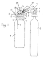
- FIG. 1 an aeration device for adding carbonic acid to water in a water bottle 1 is shown, where the neck of the water bottle is furnished with a fastening means 2 arranged to cooperate with a corresponding fastening means 3 of a pipe end 4 of the device.
- the pipe end 4 is fastened to a pipe- and valve arrangement 5, and is connected, via a controllable valve 7, to a gas bottle 6 containing carbon dioxide.
- a tube 8 runs to an orifice 9 running down into an attached water bottle 1.
- the said valve 7 is opened by a user by help of a non-locking first control means 10 which is capable of being pressed down or in.
- the control means 10 is rotatable about a hinge 11, and is operated by a user pressing down the control means by the help of a button 12.
- the control means presses down an upwardly projecting tap 13 of the gas bottle valve 7, whereby the valve 7 is opened so that gas flows from the gas bottle 6 down into the water in the water bottle via the said nozzle 9.
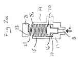
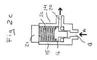
- the aeration device comprises an overpressure- and ventilating valve 14 comprising a piston 16 movable in a sleeve 15, see Figure 2a , which piston is displaceable between a first, closing position, shown in Figure 2a , and a second, opening position, shown in Figure 2c .
- the piston 16 when in its closing position is arranged to seal off an outlet channel 18, arranged at a first end 17 of the sleeve 15, from the water bottle 1.
- an O-ring 19 may be used.
- a second outlet channel 20 is arranged at the said first end 17 of the sleeve 15, arranged so that a connection between the first outlet channel 18 and the environment via the second outlet channel 20 is opened in the opening position of the piston 16.
- a second control means 21 is arranged in or at the sleeve, arranged to be displaceable in or at the sleeve 15 towards and away from the first end 17 of the sleeve, into and out from the sleeve 15, and partly or completely projecting out from the sleeve. This is influenced by the first control means 10 when pressed downwards in Figure 1 so that the second control means 21 is pressed downwards.
- a spring 22 is arranged between the piston 16 and the second control means 21 in or at the end 23 located at the sleeve 15.
- the said spring 22 has a spring constant such that the overpressure- and ventilating valve 14 opens when the first control means 10 is kept pressed down or in by a user, and the pressure in the water bottle rises above a first predetermined value.
- the pressure in a suitable gas bottle is of the magnitude 10 bars.
- the pressure in the water bottle should not rise above 8 bars.
- the piston When the pressure in the water bottle rises to the first predetermined pressure P4, for example 8 bars, the piston is pressed up against the spring force of the spring, so that the first outlet channel is connected to the environment via the second outlet channel 20.
- the pressure in the water bottle drops, and the user releases the first control means 10, 12 when the user hears that the overpressure valve has opened. Then, the first control means returns to its original position, see Figure 2a .
- a downward force is also being applied to the second control means 21 when the first control means 10, 12 has been released by the user and has sprung back.
- This force is such that the overpressure- and ventilating valve 14 opens when the pressure in the water bottle 1 surpasses a second predetermined value.
- the pressure in the water bottle is for example 8 bars.
- the said downward force corresponds to a lower pressure in the water bottle, for example less than 1.5 bars.
- the piston remains in the position shown in Figure 2d , whereby the interior of the water bottle is connected with its surroundings via the outlet channels 18, 20 until the pressure in the water bottle has sunk to for example less than said 1.5 bars.
- the overpressure- and ventilating valve 14 functions as a ventilating valve.
- the overpressure- and ventilating valve 14 closes, because of the downward force increasing above the force P2 from the pressure in the water bottle.
- the pressure P1 in Figure 2a that is the starting position, is atmospheric pressure.
- the pressure P3 in Figure 2b is the pressure during the pressurizing phase, that is above for example 8 bars.
- the pressure P4 in Figure 2c is the pressure during the time when the overpressure valve is open.
- the pressure P2 in Figure 2d is the pressure prevailing during the ventilating phase.
- the said force which is applied to the second control means 21 is applied by the first control means 10 bearing on the second control means by the force of gravity.
- the first control means 10 comprises a spring 24 acting against one of the ends of an arm 25.
- the arm 25 acts directly against the second control means 21.
- the latter spring 24 is stronger than the spring 22 in the sleeve 15, and is aimed at springing back the first control means 10 when a user releases the button 12.
- the said force, which is applied to the second control means is applied by the said spring 22 in the sleeve 15 exerting the said force as a remaining spring force when the first control means is released by the user and has sprung back.
- the second control means 21 is displaceable in a limited manner relative the said second end 26 of the sleeve 15, giving rise to the said remaining spring force.
- the first control means 10 is displaceable in a limited manner relative to the said second end 26 of the valve 14, giving rise to the said remaining spring force.
- FIG. 3 An exemplifying embodiment is shown in Figure 3 , in which the sleeve 15 is fitted with a groove 27 in which the second control means 21 runs.
- the said first predetermined pressure is between 8 and 12 bars.
- the said second predetermined pressure is between 1.1 and 1.5 bars.
- valve 14 closes during ventilation at a pressure above atmospheric pressure, for example at a pressure of 1.1 bars. This means that gas is dissolved in the water during the whole ventilating phase. In turn, this means that the water more easily can be furnished with carbon acid, and that no carbon dioxide is lost.
- the first control means 10 comprises a mechanical brake 28, arranged to delay the backspring of the first control means when the first control means is released by the user.
- the mechanical brake is illustrated with a gear wheel 28 which is braked in a suitable known way, and running against a toothed surface 29 on an arm 30 projecting downwards from an upper arm 31 of the first control means 10.
- the ventilating period becomes longer, and more gas is dissolved in the water in the water bottle.
Landscapes
- Engineering & Computer Science (AREA)
- General Engineering & Computer Science (AREA)
- Mechanical Engineering (AREA)
- Chemical & Material Sciences (AREA)
- Health & Medical Sciences (AREA)
- Nutrition Science (AREA)
- Life Sciences & Earth Sciences (AREA)
- Food Science & Technology (AREA)
- Polymers & Plastics (AREA)
- Chemical Kinetics & Catalysis (AREA)
- Closures For Containers (AREA)
- Devices For Dispensing Beverages (AREA)
Claims (6)
- Belüftungsvorrichtung zum Einleiten von Kohlensäure in Wasser, das sich in einer Wasserflasche (1) befindet,- wobei der Hals der Wasserflasche mit einem Befestigungsmittel (2) versehen ist, das so angeordnet ist, dass es mit einem entsprechenden Befestigungsmittel (3) eines Rohrendes (4) der Vorrichtung zusammenwirkt,- wobei das Rohrende (4) über ein kontrollierbares Ventil (7) mit einer Gasflasche (6), die Kohlensäure umfasst, verbunden ist,- wobei das Ventil (7) von einem Benutzer mithilfe eines nichtverriegelnden ersten Kontrollmittels (10) geöffnet wird, das herunter- oder eingedrückt werden kann, so dass Gas aus der Gasflasche (6) über eine Düse (9) nach unten in die Wasserflasche (1) strömt,- wobei die Belüftungsvorrichtung weiterhin ein Überdruck- und Belüftungsventil (14) mit einem Kolben (16) umfasst, der in einer Hülse (15) bewegbbar ist, wobei der Kolben zwischen einer ersten Schließposition und einer zweiten Öffnungsposition verschiebbar ist,wobei:- der Kolben (16) in der Schließposition so angeordnet ist, dass er einen ersten Auslasskanal (18) von der Wasserflasche (1) abdichtet, der an einem ersten Ende (17) der Hülse (15) angeordnet ist, und in der Öffnungsposition den ersten Auslasskanal (18) öffnet,- ein zweiter Auslasskanal (20) am ersten Ende (17) der Hülse vorgesehen und so angeordnet ist, dass in der Öffnungsposition des Kolbens (16) eine Verbindung zwischen dem ersten Auslasskanal (18) und der Umgebung über den zweiten Auslasskanal (20) geöffnet ist,- ein zweites Kontrollmittel (21) in oder an der Hülse (15) vorgesehen und so angeordnet ist, dass es in oder an der Hülse hin zum und weg vom ersten Ende (17) der Hülse verschiebbar ist,- eine Feder (22) zwischen dem Kolben (16) und dem Ende (23) des in oder an der Hülse befindlichen zweiten Kontrollmittels (21) angeordnet ist,- die Feder (22) eine solche Federkonstante hat, dass sich das Überdruck- und Belüftungsventil (14) öffnet, wenn das erste Kontrollmittel (10) von einem Benutzer herunter- oder eingedrückt gehalten wird und der Druck in der Wasserflasche (1) über einen ersten vorbestimmten Wert ansteigt,- eine Kraft gegen den Kolben (16) ausgeübt wird, wenn das erste Kontrollmittel (10) vom Benutzer freigegeben wird und zurückgefedert ist, wobei die Kraft so beschaffen ist, dass sich das Überdruck- und Belüftungsventil (14) schließt, wenn der Druck im ersten Auslasskanal (18) unter einen zweiten vorbestimmten Wert absinkt, wobei der zweite vorbestimmte Wert zwischen 1,1 und 1,5 bar liegt.
- Belüftungsvorrichtung nach Anspruch 1, dadurch gekennzeichnet, dass die Kraft, die gegen den Kolben (16) ausgeübt wird, durch das erste Kontrollmittel (10) auf das zweite Kontrollmittel ausgeübte Schwerkraft ist.
- Belüftungsvorrichtung nach Anspruch 1, dadurch gekennzeichnet, dass die gegen den Kolben (16) ausgeübte Kraft durch die Feder (22) erfolgt, die die Kraft als eine verbleibende Federkraft ausübt, wenn das erste Kontrollmittel (10) vom Benutzer freigegeben wird und zurückfedert.
- Belüftungsvorrichtung nach Anspruch 3, dadurch gekennzeichnet, dass das erste Kontrollmittel (10) in einer begrenzten Weise im Verhältnis zum zweiten Ende (26) der Hülse (15) verschiebbar ist, woraus sich die verbleibende Federkraft ergibt.
- Belüftungsvorrichtung nach Anspruch 1, 2, 3 oder 4, dadurch gekennzeichnet, dass der erste vorbestimmte Druck zwischen 8 und 12 bar liegt.
- Belüftungsvorrichtung nach Anspruch 1, 2, 3 oder 4, dadurch gekennzeichnet, dass das erste Kontrollmittel (10) eine mechanische Bremse (28, 29) umfasst, die angeordnet ist, um den Rückfederungsvorgang des ersten Kontrollmittels zu verzögern, wenn das erste Kontrollmittel vom Benutzer freigegeben wird.
Applications Claiming Priority (1)
| Application Number | Priority Date | Filing Date | Title |
|---|---|---|---|
| SE0950129A SE533560C2 (sv) | 2009-03-06 | 2009-03-06 | Övertrycks- och avluftningsventil för en kolsyresättningsanordning. |
Publications (2)
| Publication Number | Publication Date |
|---|---|
| EP2226539A1 EP2226539A1 (de) | 2010-09-08 |
| EP2226539B1 true EP2226539B1 (de) | 2013-10-16 |
Family
ID=41161394
Family Applications (1)
| Application Number | Title | Priority Date | Filing Date |
|---|---|---|---|
| EP09165178.6A Not-in-force EP2226539B1 (de) | 2009-03-06 | 2009-07-10 | Überdruck- und Belüftungsventil für eine Belüftungsvorrichtung |
Country Status (3)
| Country | Link |
|---|---|
| EP (1) | EP2226539B1 (de) |
| DK (1) | DK2226539T3 (de) |
| SE (1) | SE533560C2 (de) |
Families Citing this family (8)
| Publication number | Priority date | Publication date | Assignee | Title |
|---|---|---|---|---|
| ITVR20130038A1 (it) * | 2013-02-13 | 2014-08-14 | Moshe Nash Abramov | Bottiglia particolarmente per apparecchiature domestiche per la produzione di bevande gasate |
| CN106102887A (zh) * | 2014-03-27 | 2016-11-09 | 气泡饮料系统创新中心国际简化股份公司 | 碳酸化装置 |
| CN105668489A (zh) * | 2016-01-27 | 2016-06-15 | 上海旭熠电子技术有限公司 | 带排风和具有防呆功能的多品种高纯化学品自动充填装置 |
| WO2021174309A1 (en) * | 2020-03-05 | 2021-09-10 | Sodaking IPV Pty Ltd | Beverage carbonation apparatus |
| SE544314C2 (en) | 2020-03-06 | 2022-04-05 | Aarke Ab | Carbonator for producing carbonated beverage |
| CN112212041B (zh) * | 2020-09-14 | 2022-04-12 | 台州众禾金属制品有限公司 | 一种力度损失小的家用燃气自闭阀 |
| DE102020127598A1 (de) * | 2020-10-20 | 2022-04-21 | Drägerwerk AG & Co. KGaA | Sockel und Gasentnahmestelle mit einem Sockel |
| IL320208A (en) * | 2024-04-12 | 2025-11-01 | Smeg Spa | Independent gauze device |
Family Cites Families (5)
| Publication number | Priority date | Publication date | Assignee | Title |
|---|---|---|---|---|
| US2944564A (en) | 1959-05-29 | 1960-07-12 | Jr Thomas M Pettey | Pressure relief valve with remote calibration change |
| US4660740A (en) | 1986-02-18 | 1987-04-28 | The Sodamaster Company Of America | Gasification of fluids |
| JPH0731288Y2 (ja) * | 1989-03-10 | 1995-07-19 | 株式会社小松製作所 | 可変圧力制御弁 |
| ATE209958T1 (de) * | 1997-03-26 | 2001-12-15 | Kisag Ag | Vorrichtung zum karbonisieren einer flüssigkeit |
| DE202004015606U1 (de) * | 2004-10-08 | 2004-12-09 | Ds Produkte Dieter Schwarz Gmbh | Besprudelungsvorrichtung |
-
2009
- 2009-03-06 SE SE0950129A patent/SE533560C2/sv not_active IP Right Cessation
- 2009-07-10 EP EP09165178.6A patent/EP2226539B1/de not_active Not-in-force
- 2009-07-10 DK DK09165178.6T patent/DK2226539T3/da active
Also Published As
| Publication number | Publication date |
|---|---|
| SE0950129A1 (sv) | 2010-09-07 |
| SE533560C2 (sv) | 2010-10-26 |
| EP2226539A1 (de) | 2010-09-08 |
| DK2226539T3 (da) | 2014-01-20 |
Similar Documents
| Publication | Publication Date | Title |
|---|---|---|
| EP2226539B1 (de) | Überdruck- und Belüftungsventil für eine Belüftungsvorrichtung | |
| US8684240B2 (en) | Pressure reducing and regulating valve comprising a tapping mechanism for a pressure cartridge that can be attached underneath a receptacle cover | |
| EP2576423B1 (de) | Verfahren und vorrichtung zur ausgabe von getränken, insbesondere von kohlensäurehaltigen getränken | |
| CN104603709B (zh) | 具有并入减压阀的残余压力功能的减压阀 | |
| IE61523B1 (en) | Pressure capsule for spray can and spray can which utilizes such pressure capsule | |
| FR2892798B1 (fr) | Ensemble comprenant un reservoir pour fluide sous pression et un dispositif de commande du remplissage et/ou du soutirage | |
| EP0954493A4 (de) | Ventileinheit zum einlass und auslass von flüssigkeiten | |
| MXPA04000828A (es) | VaLVULA DOSIFICADORA DE FLUIDOS Y MeTODOS PARA SU USO. | |
| US3994312A (en) | Inflation pressure regulator | |
| US20180141066A1 (en) | System and method for refilling a bottle with liquid | |
| US20130233878A1 (en) | Dispensing unit and method for dispensing a liquid under pressure | |
| AU4173699A (en) | Pressure control device for maintaining a constant predetermined pressure in a container | |
| AU2002304830A1 (en) | Safety system for a liquid fuel tank | |
| CA2414097A1 (en) | Apparatus for intermittent liquid dispersal | |
| MX2008011995A (es) | Recipiente de bebida y montaje de recipiente y dispositivo de toma. | |
| EP1442225B1 (de) | Hydraulische vorrichtung mit einem belüftungsaggregat | |
| JP4576091B2 (ja) | 圧力源を容器に接続する装置および方法。 | |
| US5960485A (en) | Bidet | |
| CA2014723A1 (en) | Pressure reducing valve | |
| CN204114258U (zh) | 一种卸压安全阀 | |
| EP3039323B1 (de) | Flüssigkeitsausstossventil | |
| IN188454B (de) | ||
| KR100709471B1 (ko) | 휴대용 기체 공급 조절장치 | |
| KR100508378B1 (ko) | 급수제어장치 | |
| CN204139279U (zh) | 一种排水阀的启动机构 |
Legal Events
| Date | Code | Title | Description |
|---|---|---|---|
| PUAI | Public reference made under article 153(3) epc to a published international application that has entered the european phase |
Free format text: ORIGINAL CODE: 0009012 |
|
| AK | Designated contracting states |
Kind code of ref document: A1 Designated state(s): AT BE BG CH CY CZ DE DK EE ES FI FR GB GR HR HU IE IS IT LI LT LU LV MC MK MT NL NO PL PT RO SE SI SK SM TR |
|
| AX | Request for extension of the european patent |
Extension state: AL BA RS |
|
| 17P | Request for examination filed |
Effective date: 20101124 |
|
| 17Q | First examination report despatched |
Effective date: 20110119 |
|
| GRAP | Despatch of communication of intention to grant a patent |
Free format text: ORIGINAL CODE: EPIDOSNIGR1 |
|
| RIC1 | Information provided on ipc code assigned before grant |
Ipc: F16K 17/04 20060101AFI20130418BHEP Ipc: B01F 3/04 20060101ALI20130418BHEP Ipc: F16K 17/06 20060101ALI20130418BHEP Ipc: F16K 15/02 20060101ALI20130418BHEP Ipc: F16K 1/30 20060101ALI20130418BHEP |
|
| INTG | Intention to grant announced |
Effective date: 20130507 |
|
| RIN1 | Information on inventor provided before grant (corrected) |
Inventor name: GUSTAVSSON, RICKARD |
|
| GRAS | Grant fee paid |
Free format text: ORIGINAL CODE: EPIDOSNIGR3 |
|
| GRAA | (expected) grant |
Free format text: ORIGINAL CODE: 0009210 |
|
| AK | Designated contracting states |
Kind code of ref document: B1 Designated state(s): AT BE BG CH CY CZ DE DK EE ES FI FR GB GR HR HU IE IS IT LI LT LU LV MC MK MT NL NO PL PT RO SE SI SK SM TR |
|
| REG | Reference to a national code |
Ref country code: GB Ref legal event code: FG4D |
|
| REG | Reference to a national code |
Ref country code: CH Ref legal event code: EP |
|
| REG | Reference to a national code |
Ref country code: IE Ref legal event code: FG4D |
|
| REG | Reference to a national code |
Ref country code: AT Ref legal event code: REF Ref document number: 636673 Country of ref document: AT Kind code of ref document: T Effective date: 20131115 |
|
| REG | Reference to a national code |
Ref country code: DE Ref legal event code: R096 Ref document number: 602009019437 Country of ref document: DE Effective date: 20131212 |
|
| REG | Reference to a national code |
Ref country code: DK Ref legal event code: T3 Effective date: 20140113 |
|
| REG | Reference to a national code |
Ref country code: SE Ref legal event code: TRGR |
|
| REG | Reference to a national code |
Ref country code: NO Ref legal event code: T2 Effective date: 20131016 |
|
| REG | Reference to a national code |
Ref country code: NL Ref legal event code: VDEP Effective date: 20131016 |
|
| REG | Reference to a national code |
Ref country code: LT Ref legal event code: MG4D |
|
| PG25 | Lapsed in a contracting state [announced via postgrant information from national office to epo] |
Ref country code: NL Free format text: LAPSE BECAUSE OF FAILURE TO SUBMIT A TRANSLATION OF THE DESCRIPTION OR TO PAY THE FEE WITHIN THE PRESCRIBED TIME-LIMIT Effective date: 20131016 Ref country code: LT Free format text: LAPSE BECAUSE OF FAILURE TO SUBMIT A TRANSLATION OF THE DESCRIPTION OR TO PAY THE FEE WITHIN THE PRESCRIBED TIME-LIMIT Effective date: 20131016 Ref country code: BE Free format text: LAPSE BECAUSE OF FAILURE TO SUBMIT A TRANSLATION OF THE DESCRIPTION OR TO PAY THE FEE WITHIN THE PRESCRIBED TIME-LIMIT Effective date: 20131016 Ref country code: HR Free format text: LAPSE BECAUSE OF FAILURE TO SUBMIT A TRANSLATION OF THE DESCRIPTION OR TO PAY THE FEE WITHIN THE PRESCRIBED TIME-LIMIT Effective date: 20131016 Ref country code: IS Free format text: LAPSE BECAUSE OF FAILURE TO SUBMIT A TRANSLATION OF THE DESCRIPTION OR TO PAY THE FEE WITHIN THE PRESCRIBED TIME-LIMIT Effective date: 20140216 |
|
| PG25 | Lapsed in a contracting state [announced via postgrant information from national office to epo] |
Ref country code: LV Free format text: LAPSE BECAUSE OF FAILURE TO SUBMIT A TRANSLATION OF THE DESCRIPTION OR TO PAY THE FEE WITHIN THE PRESCRIBED TIME-LIMIT Effective date: 20131016 Ref country code: CY Free format text: LAPSE BECAUSE OF FAILURE TO SUBMIT A TRANSLATION OF THE DESCRIPTION OR TO PAY THE FEE WITHIN THE PRESCRIBED TIME-LIMIT Effective date: 20131016 Ref country code: ES Free format text: LAPSE BECAUSE OF FAILURE TO SUBMIT A TRANSLATION OF THE DESCRIPTION OR TO PAY THE FEE WITHIN THE PRESCRIBED TIME-LIMIT Effective date: 20131016 |
|
| PG25 | Lapsed in a contracting state [announced via postgrant information from national office to epo] |
Ref country code: PT Free format text: LAPSE BECAUSE OF FAILURE TO SUBMIT A TRANSLATION OF THE DESCRIPTION OR TO PAY THE FEE WITHIN THE PRESCRIBED TIME-LIMIT Effective date: 20140217 |
|
| REG | Reference to a national code |
Ref country code: DE Ref legal event code: R097 Ref document number: 602009019437 Country of ref document: DE |
|
| PG25 | Lapsed in a contracting state [announced via postgrant information from national office to epo] |
Ref country code: EE Free format text: LAPSE BECAUSE OF FAILURE TO SUBMIT A TRANSLATION OF THE DESCRIPTION OR TO PAY THE FEE WITHIN THE PRESCRIBED TIME-LIMIT Effective date: 20131016 |
|
| PLBE | No opposition filed within time limit |
Free format text: ORIGINAL CODE: 0009261 |
|
| STAA | Information on the status of an ep patent application or granted ep patent |
Free format text: STATUS: NO OPPOSITION FILED WITHIN TIME LIMIT |
|
| PG25 | Lapsed in a contracting state [announced via postgrant information from national office to epo] |
Ref country code: RO Free format text: LAPSE BECAUSE OF FAILURE TO SUBMIT A TRANSLATION OF THE DESCRIPTION OR TO PAY THE FEE WITHIN THE PRESCRIBED TIME-LIMIT Effective date: 20131016 Ref country code: CZ Free format text: LAPSE BECAUSE OF FAILURE TO SUBMIT A TRANSLATION OF THE DESCRIPTION OR TO PAY THE FEE WITHIN THE PRESCRIBED TIME-LIMIT Effective date: 20131016 Ref country code: SK Free format text: LAPSE BECAUSE OF FAILURE TO SUBMIT A TRANSLATION OF THE DESCRIPTION OR TO PAY THE FEE WITHIN THE PRESCRIBED TIME-LIMIT Effective date: 20131016 Ref country code: PL Free format text: LAPSE BECAUSE OF FAILURE TO SUBMIT A TRANSLATION OF THE DESCRIPTION OR TO PAY THE FEE WITHIN THE PRESCRIBED TIME-LIMIT Effective date: 20131016 |
|
| 26N | No opposition filed |
Effective date: 20140717 |
|
| REG | Reference to a national code |
Ref country code: DE Ref legal event code: R097 Ref document number: 602009019437 Country of ref document: DE Effective date: 20140717 |
|
| PG25 | Lapsed in a contracting state [announced via postgrant information from national office to epo] |
Ref country code: SI Free format text: LAPSE BECAUSE OF FAILURE TO SUBMIT A TRANSLATION OF THE DESCRIPTION OR TO PAY THE FEE WITHIN THE PRESCRIBED TIME-LIMIT Effective date: 20131016 Ref country code: LU Free format text: LAPSE BECAUSE OF FAILURE TO SUBMIT A TRANSLATION OF THE DESCRIPTION OR TO PAY THE FEE WITHIN THE PRESCRIBED TIME-LIMIT Effective date: 20140710 |
|
| REG | Reference to a national code |
Ref country code: IE Ref legal event code: MM4A |
|
| PG25 | Lapsed in a contracting state [announced via postgrant information from national office to epo] |
Ref country code: IE Free format text: LAPSE BECAUSE OF NON-PAYMENT OF DUE FEES Effective date: 20140710 |
|
| PG25 | Lapsed in a contracting state [announced via postgrant information from national office to epo] |
Ref country code: MC Free format text: LAPSE BECAUSE OF FAILURE TO SUBMIT A TRANSLATION OF THE DESCRIPTION OR TO PAY THE FEE WITHIN THE PRESCRIBED TIME-LIMIT Effective date: 20131016 Ref country code: SM Free format text: LAPSE BECAUSE OF FAILURE TO SUBMIT A TRANSLATION OF THE DESCRIPTION OR TO PAY THE FEE WITHIN THE PRESCRIBED TIME-LIMIT Effective date: 20131016 |
|
| REG | Reference to a national code |
Ref country code: FR Ref legal event code: PLFP Year of fee payment: 8 |
|
| PG25 | Lapsed in a contracting state [announced via postgrant information from national office to epo] |
Ref country code: MT Free format text: LAPSE BECAUSE OF FAILURE TO SUBMIT A TRANSLATION OF THE DESCRIPTION OR TO PAY THE FEE WITHIN THE PRESCRIBED TIME-LIMIT Effective date: 20131016 Ref country code: BG Free format text: LAPSE BECAUSE OF FAILURE TO SUBMIT A TRANSLATION OF THE DESCRIPTION OR TO PAY THE FEE WITHIN THE PRESCRIBED TIME-LIMIT Effective date: 20131016 Ref country code: GR Free format text: LAPSE BECAUSE OF FAILURE TO SUBMIT A TRANSLATION OF THE DESCRIPTION OR TO PAY THE FEE WITHIN THE PRESCRIBED TIME-LIMIT Effective date: 20140117 |
|
| PG25 | Lapsed in a contracting state [announced via postgrant information from national office to epo] |
Ref country code: TR Free format text: LAPSE BECAUSE OF FAILURE TO SUBMIT A TRANSLATION OF THE DESCRIPTION OR TO PAY THE FEE WITHIN THE PRESCRIBED TIME-LIMIT Effective date: 20131016 Ref country code: HU Free format text: LAPSE BECAUSE OF FAILURE TO SUBMIT A TRANSLATION OF THE DESCRIPTION OR TO PAY THE FEE WITHIN THE PRESCRIBED TIME-LIMIT; INVALID AB INITIO Effective date: 20090710 |
|
| PGFP | Annual fee paid to national office [announced via postgrant information from national office to epo] |
Ref country code: FR Payment date: 20160613 Year of fee payment: 8 |
|
| PGFP | Annual fee paid to national office [announced via postgrant information from national office to epo] |
Ref country code: GB Payment date: 20160706 Year of fee payment: 8 Ref country code: DE Payment date: 20160705 Year of fee payment: 8 Ref country code: IT Payment date: 20160720 Year of fee payment: 8 Ref country code: DK Payment date: 20160712 Year of fee payment: 8 Ref country code: CH Payment date: 20160712 Year of fee payment: 8 Ref country code: FI Payment date: 20160711 Year of fee payment: 8 Ref country code: NO Payment date: 20160713 Year of fee payment: 8 |
|
| PGFP | Annual fee paid to national office [announced via postgrant information from national office to epo] |
Ref country code: SE Payment date: 20160712 Year of fee payment: 8 Ref country code: AT Payment date: 20160630 Year of fee payment: 8 |
|
| REG | Reference to a national code |
Ref country code: DE Ref legal event code: R119 Ref document number: 602009019437 Country of ref document: DE |
|
| REG | Reference to a national code |
Ref country code: DK Ref legal event code: EBP Effective date: 20170731 Ref country code: NO Ref legal event code: MMEP |
|
| REG | Reference to a national code |
Ref country code: CH Ref legal event code: PL |
|
| REG | Reference to a national code |
Ref country code: SE Ref legal event code: EUG |
|
| REG | Reference to a national code |
Ref country code: AT Ref legal event code: MM01 Ref document number: 636673 Country of ref document: AT Kind code of ref document: T Effective date: 20170710 |
|
| GBPC | Gb: european patent ceased through non-payment of renewal fee |
Effective date: 20170710 |
|
| REG | Reference to a national code |
Ref country code: FR Ref legal event code: ST Effective date: 20180330 |
|
| PG25 | Lapsed in a contracting state [announced via postgrant information from national office to epo] |
Ref country code: LI Free format text: LAPSE BECAUSE OF NON-PAYMENT OF DUE FEES Effective date: 20170731 Ref country code: NO Free format text: LAPSE BECAUSE OF NON-PAYMENT OF DUE FEES Effective date: 20170731 Ref country code: GB Free format text: LAPSE BECAUSE OF NON-PAYMENT OF DUE FEES Effective date: 20170710 Ref country code: SE Free format text: LAPSE BECAUSE OF NON-PAYMENT OF DUE FEES Effective date: 20170711 Ref country code: FI Free format text: LAPSE BECAUSE OF NON-PAYMENT OF DUE FEES Effective date: 20170710 Ref country code: CH Free format text: LAPSE BECAUSE OF NON-PAYMENT OF DUE FEES Effective date: 20170731 Ref country code: DE Free format text: LAPSE BECAUSE OF NON-PAYMENT OF DUE FEES Effective date: 20180201 |
|
| PG25 | Lapsed in a contracting state [announced via postgrant information from national office to epo] |
Ref country code: FR Free format text: LAPSE BECAUSE OF NON-PAYMENT OF DUE FEES Effective date: 20170731 Ref country code: AT Free format text: LAPSE BECAUSE OF NON-PAYMENT OF DUE FEES Effective date: 20170710 |
|
| PG25 | Lapsed in a contracting state [announced via postgrant information from national office to epo] |
Ref country code: MK Free format text: LAPSE BECAUSE OF FAILURE TO SUBMIT A TRANSLATION OF THE DESCRIPTION OR TO PAY THE FEE WITHIN THE PRESCRIBED TIME-LIMIT Effective date: 20131016 |
|
| PG25 | Lapsed in a contracting state [announced via postgrant information from national office to epo] |
Ref country code: DK Free format text: LAPSE BECAUSE OF NON-PAYMENT OF DUE FEES Effective date: 20170731 |
|
| PG25 | Lapsed in a contracting state [announced via postgrant information from national office to epo] |
Ref country code: IT Free format text: LAPSE BECAUSE OF NON-PAYMENT OF DUE FEES Effective date: 20170710 |