EP2226505A1 - Free flow impeller with cutting edges - Google Patents
Free flow impeller with cutting edges Download PDFInfo
- Publication number
- EP2226505A1 EP2226505A1 EP10001468A EP10001468A EP2226505A1 EP 2226505 A1 EP2226505 A1 EP 2226505A1 EP 10001468 A EP10001468 A EP 10001468A EP 10001468 A EP10001468 A EP 10001468A EP 2226505 A1 EP2226505 A1 EP 2226505A1
- Authority
- EP
- European Patent Office
- Prior art keywords
- blades
- cutting edges
- winglets
- centrifugal pump
- front surfaces
- Prior art date
- Legal status (The legal status is an assumption and is not a legal conclusion. Google has not performed a legal analysis and makes no representation as to the accuracy of the status listed.)
- Granted
Links
- 239000007787 solid Substances 0.000 claims description 5
- 238000005266 casting Methods 0.000 description 4
- 230000000694 effects Effects 0.000 description 3
- 239000012530 fluid Substances 0.000 description 2
- 239000007788 liquid Substances 0.000 description 2
- 239000004753 textile Substances 0.000 description 2
- 238000011144 upstream manufacturing Methods 0.000 description 2
- 230000035508 accumulation Effects 0.000 description 1
- 238000009825 accumulation Methods 0.000 description 1
- 230000002411 adverse Effects 0.000 description 1
- 230000009286 beneficial effect Effects 0.000 description 1
- 230000002349 favourable effect Effects 0.000 description 1
- 239000000835 fiber Substances 0.000 description 1
- 230000006698 induction Effects 0.000 description 1
- 239000002184 metal Substances 0.000 description 1
- 230000007704 transition Effects 0.000 description 1
Images


Classifications
-
- F—MECHANICAL ENGINEERING; LIGHTING; HEATING; WEAPONS; BLASTING
- F04—POSITIVE - DISPLACEMENT MACHINES FOR LIQUIDS; PUMPS FOR LIQUIDS OR ELASTIC FLUIDS
- F04D—NON-POSITIVE-DISPLACEMENT PUMPS
- F04D7/00—Pumps adapted for handling specific fluids, e.g. by selection of specific materials for pumps or pump parts
- F04D7/02—Pumps adapted for handling specific fluids, e.g. by selection of specific materials for pumps or pump parts of centrifugal type
- F04D7/04—Pumps adapted for handling specific fluids, e.g. by selection of specific materials for pumps or pump parts of centrifugal type the fluids being viscous or non-homogenous
- F04D7/045—Pumps adapted for handling specific fluids, e.g. by selection of specific materials for pumps or pump parts of centrifugal type the fluids being viscous or non-homogenous with means for comminuting, mixing stirring or otherwise treating
-
- F—MECHANICAL ENGINEERING; LIGHTING; HEATING; WEAPONS; BLASTING
- F04—POSITIVE - DISPLACEMENT MACHINES FOR LIQUIDS; PUMPS FOR LIQUIDS OR ELASTIC FLUIDS
- F04D—NON-POSITIVE-DISPLACEMENT PUMPS
- F04D29/00—Details, component parts, or accessories
- F04D29/18—Rotors
- F04D29/22—Rotors specially for centrifugal pumps
- F04D29/2238—Special flow patterns
- F04D29/2244—Free vortex
Definitions
- the invention relates to a centrifugal pump for conveying a solid admixed medium with a housing in which a free-flow impeller is arranged and a vane-free space is formed between the free-flow impeller and the inlet-side housing wall, wherein the free-flow impeller comprises a support disc, are formed on the blades, have the pressure side side surfaces, suction side side surfaces and front surfaces.
- the impeller is flowed in radially on the inside.
- the fluid flows radially outward from the impeller.
- a radially inward flow is formed.
- admixtures whose densities correspond approximately to the average density of the pumped liquid, or smaller, can accumulate on the center of the impeller.
- fibrous or textile admixtures there is a risk that the residence time in the center of the impeller will be so great that accumulations build up. This can become one Clog the pump. Therefore, there are numerous versions of free-flow pumps, which are equipped with shredders.
- a centrifugal pump is described with a pump impeller upstream crushing device for fibrous or lumpy admixtures in the fluid.
- the comminution device is formed by a rotating with the pump impeller cutting head and a stationary in the housing of the centrifugal pump cutting ring. Due to the upstream shredding device, however, the space in front of the impeller is reduced and the inflow into the impeller is influenced. This can have a negative effect on the pump characteristic.
- Object of the present invention is to develop a centrifugal pump for the promotion of liquids with solid admixtures, are avoided in the blockages.
- An attachment of fibrous components, such as textiles or films should be prevented.
- the free passage through the pump should not be hindered.
- the characteristic curve of the pump should not be adversely affected.
- the blades are provided with cutting edges.
- the blades provided with cutting edges cut through the solid admixtures, so that deposits can not occur. It is particularly advantageous if all or more blades are provided with cutting edges. In individual cases, however, it is sufficient if only one blade has a cutting edge.
- cutting edges are formed at the locations where the front surfaces of the blades strike the side surfaces.
- the impeller is a casting.
- the contact points where the front surfaces and the side surfaces of the blades meet are not sharp-edged with conventional free-stream pumps. There is no defined line of contact between the front surfaces and the side surfaces but there is an area in which the surfaces merge. The area is not defined sharp-edged but it is a rounded transition.
- At least one surface of the blades is machined such that cutting edges are formed at the contact points of the surfaces.
- the surfaces can be processed by grinding or planing.
- the cutting action and the wear behavior can be improved by a local hardening of the cutting edges.
- the front surfaces of the blades are machined to form cutting edges.
- the front surfaces are prepared by grinding or planing so that cutting edges are formed.
- the side surfaces of the blades are formed by the casting skin.
- the front surfaces of the blades can only be provided with a chamfer.
- the front surfaces of the blades are preferably chamfered in the areas where the front surfaces meet the pressure-side side surfaces of the blades.
- the cutting or tearing effect of the cutting edges is supported by the casting roughness.
- the hard casting skin counteracts the wear.
- the surfaces forming the cutting edges are preferably at an angle smaller than 120 ° to each other. It proves to be advantageous if the surfaces which form the cutting edges are at an angle of less than 90 ° to each other.
- the cutting edges are formed on the contact lines, at which the front surfaces meet the pressure-side side surfaces. This will be a particularly effective Cutting effect of the edges achieved because due to the direction of rotation of the impeller, the admixtures are pressed to the pressure-side side surfaces.
- the front surfaces of the blades are formed as winglets, which overlap the side surfaces.
- the winglets are additional surfaces that are usually perpendicular to the blades.
- the winglets improve the efficiency of the pump.
- the winglets project beyond the suction-side side surfaces of the blades.
- the winglets are provided with cutting edges. Impellers with winglets achieve their optimum effectiveness at very small blade angles. This is contrary to the cutting action. In addition, the winglets offer an additional area to which stable cutting edges can be attached.
- blades are mounted on the winglets.
- the blades are metal plates provided with cutting edges.
- the blades are preferably screwed onto the winglets.
- Another preferred variant of the invention is to provide the winglets with grooves.
- the grooves are introduced on the inlet side surfaces of the winglets.
- the grooves create cutting edges on the inlet side surface of the winglets.
- the cutting edges are formed at the contact lines where the side walls of the grooves meet the surface of the winglets.
- the flat surface of the winglets can be provided with recesses.
- the serrated grooves can be either circular or spiral.
- the grooves preferably have a wedge-shaped cross-sectional profile.
- a blade extension projects beyond the winglet surface. This blade extension points towards the inlet side housing wall.
- These blade extensions can be over-turned or ground, so that cutting edges are formed in this way. Through induction hardening, the cutting edges can be additionally strengthened.
- blades with flat outlet-side blade angles ⁇ are preferably used. It also proves to be beneficial to use impellers with a few blades, with a number of four or fewer blades has been found to be advantageous. Impellers with a shallow blade angle and a few blades are particularly well suited, as fibers slide radially outwards and are thereby comminuted. Free-flow impellers with a steep blade angle and many blades are less well suited, since sliding against the direction of rotation is difficult.
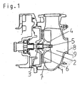
- a centrifugal pump in whose housing 1 a free-flow impeller 2 is positioned.
- the free stream wheel 2 is mounted on a shaft 3.
- the attachment of the freewheel wheel 2 is a hub body 4, in which a screw 5 engages.
- On the support disk 6 of the freewheel wheel 2 a plurality of blades 7 are arranged. Between the free stream wheel 2 and the inlet-side housing wall 8, a blade-free space 9 is formed.
- a freewheel wheel 2 with cutting edges 14 is shown.
- the free stream wheel 2 turns counterclockwise.
- blades 7 are arranged.
- Winglets 10 are formed.
- the winglets 10 project beyond the suction-side side surfaces 11 of the blades 7.
- the front surfaces 12 of the blades 7 are chamfered to the pressure-side side surface 13.
- Cutting edges 14 are formed at the contact lines between the front surfaces 12 and the pressure-side side surfaces 13 of the blades 7.
- Fig. 2b one recognizes an exit-side blade angle ⁇ .
- the grooves 15 are recesses in the inlet-side surfaces of the winglets 10.
- the grooves 15 can be introduced into the surfaces of the winglets in the form of notches.
- the grooves 15 have a wedge-shaped cross-sectional profile.
Landscapes
- Engineering & Computer Science (AREA)
- Mechanical Engineering (AREA)
- General Engineering & Computer Science (AREA)
- Structures Of Non-Positive Displacement Pumps (AREA)
Abstract
Description
Die Erfindung betrifft eine Kreiselpumpe zur Förderung eines mit festen Beimengungen versetzten Mediums mit einem Gehäuse, in dem ein Freistromrad angeordnet ist und zwischen dem Freistromrad und der einlassseitigen Gehäusewand ein schaufelfreier Raum gebildet wird, wobei das Freistromrad eine Tragscheibe umfasst, auf der Schaufeln angeformt sind, die druckseitige Seitenflächen, saugseitige Seitenflächen und Vorderflächen aufweisen.The invention relates to a centrifugal pump for conveying a solid admixed medium with a housing in which a free-flow impeller is arranged and a vane-free space is formed between the free-flow impeller and the inlet-side housing wall, wherein the free-flow impeller comprises a support disc, are formed on the blades, have the pressure side side surfaces, suction side side surfaces and front surfaces.
Pumpen mit Freistromrädern weisen einen großen Abstand zwischen den Laufrad-Schaufeln und der einlassseitigen Gehäusewand auf, wodurch ein freier Raum gebildet wird. Dadurch wird die Mitförderung von festen Beimengungen ermöglicht, selbst dann, wenn die Beimengungen große Abmessungen haben.Pumps with free-flow wheels have a large distance between the impeller blades and the inlet-side housing wall, whereby a free space is formed. This allows the co-promotion of solid admixtures, even if the admixtures have large dimensions.
Das Laufrad wird radial innen angeströmt. Das Fluid strömt vom Laufrad radial nach außen ab. Im Raum zwischen Laufrad und einlassseitiger Gehäusewand bildet sich eine radial nach innen gerichtete Strömung. Dadurch können sich Beimengungen, deren Dichten in etwa der durchschnittlichen Dichte der Förderflüssigkeit entsprechen, oder kleiner ist, auf der Laufradmitte anlagern. Handelt es sich dabei um faserige oder textile Beimengungen, besteht die Gefahr, dass die Verweildauer im Bereich der Laufradmitte so groß wird, dass sich Anlagerungen aufbauen. Dies kann zu einem Verstopfen der Pumpe führen. Daher gibt es zahlreiche Ausführungen von Freistrompumpen, die mit Zerkleinerungseinrichtungen ausgestattet sind.The impeller is flowed in radially on the inside. The fluid flows radially outward from the impeller. In the space between the impeller and inlet-side housing wall, a radially inward flow is formed. As a result, admixtures whose densities correspond approximately to the average density of the pumped liquid, or smaller, can accumulate on the center of the impeller. In the case of fibrous or textile admixtures, there is a risk that the residence time in the center of the impeller will be so great that accumulations build up. This can become one Clog the pump. Therefore, there are numerous versions of free-flow pumps, which are equipped with shredders.
In der
Aufgabe der vorliegenden Erfindung ist es, eine Kreiselpumpe zur Förderung von Flüssigkeiten mit festen Beimengungen zu entwickeln, bei der Verstopfungen vermieden werden. Ein Anhängen von faserigen Bestandteilen, wie beispielsweise Textilien oder Folien, soll verhindert werden. Dabei soll der freie Durchgang durch die Pumpe nicht behindert werden. Weiterhin soll die Kennliniencharakteristik der Pumpe nicht negativ beeinflusst werden.Object of the present invention is to develop a centrifugal pump for the promotion of liquids with solid admixtures, are avoided in the blockages. An attachment of fibrous components, such as textiles or films should be prevented. The free passage through the pump should not be hindered. Furthermore, the characteristic curve of the pump should not be adversely affected.
Diese Aufgabe wird erfindungsgemäß dadurch gelöst, dass die Schaufeln mit Schneidkanten versehen sind. Die mit Schneidkanten versehenen Schaufeln durchtrennen die festen Beimengungen, so dass es nicht zu Anlagerungen kommen kann. Dabei ist es besonders vorteilhaft, wenn alle oder mehrere Schaufeln mit Schneidkanten versehen sind. Im Einzelfall reicht es jedoch auch aus, wenn nur eine Schaufel eine Schneidkante aufweist.This object is achieved in that the blades are provided with cutting edges. The blades provided with cutting edges cut through the solid admixtures, so that deposits can not occur. It is particularly advantageous if all or more blades are provided with cutting edges. In individual cases, however, it is sufficient if only one blade has a cutting edge.
In einer bevorzugten Ausführungsform der Erfindung werden Schneidkanten an den Stellen gebildet, an denen die Vorderflächen der Schaufeln auf die Seitenflächen treffen.In a preferred embodiment of the invention, cutting edges are formed at the locations where the front surfaces of the blades strike the side surfaces.
Üblicherweise handelt es sich bei dem Laufrad um ein Gussteil. Die Berührungsstellen an denen die Vorderflächen und die Seitenflächen der Schaufeln aufeinander treffen sind bei herkömmlichen Freistrompumpen nicht scharfkantig. Es gibt keine definierte Berührungslinie zwischen den Vorderflächen und den Seitenflächen sondern einen Bereich, in dem die Flächen ineinander übergehen. Der Bereich ist dabei nicht scharfkantig abgegrenzt sondern es handelt sich um einen abgerundeten Übergang.Usually, the impeller is a casting. The contact points where the front surfaces and the side surfaces of the blades meet are not sharp-edged with conventional free-stream pumps. There is no defined line of contact between the front surfaces and the side surfaces but there is an area in which the surfaces merge. The area is not defined sharp-edged but it is a rounded transition.
Im Gegensatz zu herkömmlichen Schaufeln wird erfindungsgemäß zumindest eine Fläche der Schaufeln so bearbeitet, dass Schneidkanten an den Berührungsstellen der Flächen gebildet werden. Zur Bildung von Schneidkanten können die Flächen durch Anschleifen oder planes Andrehen bearbeitet werden. Zusätzlich können die Schneidwirkung und das Verschleißverhalten durch eine örtliche Härtung der Schneidkanten verbessert werden.In contrast to conventional blades, according to the invention at least one surface of the blades is machined such that cutting edges are formed at the contact points of the surfaces. To form cutting edges, the surfaces can be processed by grinding or planing. In addition, the cutting action and the wear behavior can be improved by a local hardening of the cutting edges.
In einer besonders vorteilhaften Ausführungsform der Erfindung werden zur Bildung von Schneidkanten die Vorderflächen der Schaufeln bearbeitet. Die Vorderflächen werden durch Anschleifen oder planes Andrehen so präpariert, dass Schneidkanten entstehen. Die Seitenflächen der Schaufeln werden von der Gusshaut gebildet.In a particularly advantageous embodiment of the invention, the front surfaces of the blades are machined to form cutting edges. The front surfaces are prepared by grinding or planing so that cutting edges are formed. The side surfaces of the blades are formed by the casting skin.
Um nicht die gesamte Planfläche bearbeiten zu müssen, können die Vorderflächen der Schaufeln lediglich mit einer Fase versehen werden. Die Vorderflächen der Schaufeln werden dabei vorzugsweise in den Bereichen angefast, wo die Vorderflächen auf die druckseitigen Seitenflächen der Schaufeln treffen. Die Schneid- oder Reißwirkung der Schneidkanten wird durch die Gussrauhigkeit unterstützt. Zusätzlich wirkt die harte Gusshaut dem Verschleiß entgegen.In order not to have to work the entire flat surface, the front surfaces of the blades can only be provided with a chamfer. The front surfaces of the blades are preferably chamfered in the areas where the front surfaces meet the pressure-side side surfaces of the blades. The cutting or tearing effect of the cutting edges is supported by the casting roughness. In addition, the hard casting skin counteracts the wear.
Die Flächen, welche die Schneidkanten bilden, stehen vorzugsweise in einem Winkel kleiner als 120 ° zueinander. Dabei erweist es sich als vorteilhaft, wenn die Flächen, welche die Schneidkanten bilden, in einem Winkel von weniger als 90 ° zueinander stehen.The surfaces forming the cutting edges are preferably at an angle smaller than 120 ° to each other. It proves to be advantageous if the surfaces which form the cutting edges are at an angle of less than 90 ° to each other.
In einer besonders vorteilhaften Ausführungsform der Erfindung werden die Schneidkanten an den Berührungslinien gebildet, an denen die Vorderflächen auf die druckseitigen Seitenflächen treffen. Dadurch wird eine besonders wirkungsvolle Schneidwirkung der Kanten erzielt, da aufgrund der Drehrichtung des Laufrades die Beimengungen an die druckseitigen Seitenflächen gepresst werden.In a particularly advantageous embodiment of the invention, the cutting edges are formed on the contact lines, at which the front surfaces meet the pressure-side side surfaces. This will be a particularly effective Cutting effect of the edges achieved because due to the direction of rotation of the impeller, the admixtures are pressed to the pressure-side side surfaces.
In einer vorteilhaften Ausführungsform der Erfindung sind die Vorderflächen der Schaufeln als Winglets ausgebildet, welche die Seitenflächen überlappen. Bei den Winglets handelt es sich um Zusatzflächen, die meist senkrecht auf den Schaufeln stehen. Durch die Winglets wird der Wirkungsgrad der Pumpe verbessert. Vorzugsweise überragen die Winglets die saugseitigen Seitenflächen der Schaufeln.In an advantageous embodiment of the invention, the front surfaces of the blades are formed as winglets, which overlap the side surfaces. The winglets are additional surfaces that are usually perpendicular to the blades. The winglets improve the efficiency of the pump. Preferably, the winglets project beyond the suction-side side surfaces of the blades.
Als besonders günstig erweist es sich, wenn die Winglets mit Schneidkanten versehen sind. Laufräder mit Winglets erreichen ihre optimale Wirksamkeit bei sehr kleinen Schaufelwinkeln. Dies kommt der Schneidwirkung entgegen. Zudem bieten die Winglets eine zusätzliche Fläche, an denen sich stabile Schneidkanten anbringen lassen.It proves to be particularly favorable if the winglets are provided with cutting edges. Impellers with winglets achieve their optimum effectiveness at very small blade angles. This is contrary to the cutting action. In addition, the winglets offer an additional area to which stable cutting edges can be attached.
In einer vorteilhaften Ausführung der Erfindung werden Klingen auf den Winglets befestigt. Bei den Klingen handelt es sich um Metallplättchen, die mit Schneidkanten versehen sind. Die Klingen werden vorzugsweise auf die Winglets aufgeschraubt.In an advantageous embodiment of the invention, blades are mounted on the winglets. The blades are metal plates provided with cutting edges. The blades are preferably screwed onto the winglets.
Eine weitere bevorzugte Variante der Erfindung besteht darin, die Winglets mit Rillen zu versehen. Die Rillen werden auf den einlassseitigen Oberflächen der Winglets eingebracht. Durch die Rillen werden auf der einlassseitigen Oberfläche der Winglets Schneidkanten erzeugt. Die Schneidkanten entstehen an den Berührungslinien, an denen die Seitenwände der Rillen auf die Oberfläche der Winglets treffen. Zur Bildung von Rillen kann die Planfläche der Winglets mit Eindrehungen versehen werden. Die kerbenförmigen Eindrehungen können entweder kreisförmig oder spiralförmig verlaufen. Die Rillen haben vorzugsweise ein keilförmiges Querschnittsprofil.Another preferred variant of the invention is to provide the winglets with grooves. The grooves are introduced on the inlet side surfaces of the winglets. The grooves create cutting edges on the inlet side surface of the winglets. The cutting edges are formed at the contact lines where the side walls of the grooves meet the surface of the winglets. To form grooves, the flat surface of the winglets can be provided with recesses. The serrated grooves can be either circular or spiral. The grooves preferably have a wedge-shaped cross-sectional profile.
Bei einer bevorzugten Ausführungsform der Erfindung ragt eine Schaufelverlängerung über die Wingletfläche hinaus. Diese Schaufelverlängerung weist Richtung einlassseitiger Gehäusewand. Diese Schaufelverlängerungen können überdreht oder überschliffen werden, so dass auf diese Weise Schneidkanten gebildet werden. Durch Induktionshärten können die Schneidkanten zusätzlich gefestigt werden.In a preferred embodiment of the invention, a blade extension projects beyond the winglet surface. This blade extension points towards the inlet side housing wall. These blade extensions can be over-turned or ground, so that cutting edges are formed in this way. Through induction hardening, the cutting edges can be additionally strengthened.
Vorzugsweise werden bei der erfindungsgemäßen Kreiselpumpe Schaufeln mit flachen austrittsseitigen Schaufelwinkeln β eingesetzt. Auch erweist es sich als günstig, Laufräder mit wenigen Schaufeln einzusetzen, wobei sich eine Anzahl von vier oder weniger Schaufeln als vorteilhaft erwiesen hat. Laufräder mit einem flachen Schaufelwinkel und wenigen Schaufeln eignen sich besonders gut, da Fasern radial nach außen abgleiten und dabei zerkleinert werden. Freistromräder mit einem steilen Schaufelwinkel und vielen Schaufeln sind weniger gut geeignet, da ein Abgleiten entgegen der Drehrichtung erschwert wird.In the case of the centrifugal pump according to the invention, blades with flat outlet-side blade angles β are preferably used. It also proves to be beneficial to use impellers with a few blades, with a number of four or fewer blades has been found to be advantageous. Impellers with a shallow blade angle and a few blades are particularly well suited, as fibers slide radially outwards and are thereby comminuted. Free-flow impellers with a steep blade angle and many blades are less well suited, since sliding against the direction of rotation is difficult.
Weitere Merkmale und Vorteile der Erfindung ergeben sich anhand der Beschreibung von Ausführungsbeispielen, anhand von Zeichnungen und aus den Zeichnungen selbst. Dabei zeigt
- Fig. 1
- einen Schnitt durch eine Freistrompumpe,
- Fig. 2
- ein Freistromrad mit Winglets und angefaster Vorderfläche, a.) als Schnitt, b.) als Draufsicht, c.) in perspektivischer Darstellung,
- Fig. 3
- ein Freistromrad mit Winglets und einem kreisförmigen Rillenverlauf, a.) als Schnitt, b.) als Draufsicht, c.) in perspektivischer Darstellung,
- Fig. 4
- ein Freistromrad mit Winglets und einem spiralförmigen Rillenverlauf, a.) als Schnitt, b.) als Draufsicht, c.) in perspektivischer Darstellung.
- Fig. 1
- a section through a free-flow pump,
- Fig. 2
- a freestyle wheel with winglets and chamfered front surface, a.) as a section, b.) as a top view, c.) in a perspective view,
- Fig. 3
- a freestyle wheel with winglets and a circular groove course, a.) as a section, b.) as a plan view, c.) in a perspective view,
- Fig. 4
- a freestyle wheel with winglets and a spiral groove course, a.) as a section, b.) as a plan view, c.) in a perspective view.
In
In
In den
Claims (9)
Applications Claiming Priority (1)
| Application Number | Priority Date | Filing Date | Title |
|---|---|---|---|
| DE102009011444A DE102009011444A1 (en) | 2009-03-03 | 2009-03-03 | Free-flow impeller with cutting edges |
Publications (2)
| Publication Number | Publication Date |
|---|---|
| EP2226505A1 true EP2226505A1 (en) | 2010-09-08 |
| EP2226505B1 EP2226505B1 (en) | 2013-11-27 |
Family
ID=42112002
Family Applications (1)
| Application Number | Title | Priority Date | Filing Date |
|---|---|---|---|
| EP10001468.7A Active EP2226505B1 (en) | 2009-03-03 | 2010-02-12 | Free flow impeller with cutting edges |
Country Status (5)
| Country | Link |
|---|---|
| EP (1) | EP2226505B1 (en) |
| CN (1) | CN101825089B (en) |
| DE (1) | DE102009011444A1 (en) |
| DK (1) | DK2226505T3 (en) |
| ES (1) | ES2443550T3 (en) |
Cited By (5)
| Publication number | Priority date | Publication date | Assignee | Title |
|---|---|---|---|---|
| EP2441877A3 (en) * | 2010-10-15 | 2014-09-03 | BSH Bosch und Siemens Hausgeräte GmbH | Household device for treating laundry with a pump |
| ITMI20130608A1 (en) * | 2013-04-12 | 2014-10-13 | Pompe Rotomec S R L | IMPELLER FOR ANTI-CLOGGING AND HIGH HYDRAULIC PERFORMANCE PUMPS |
| EP2868928A1 (en) * | 2013-10-31 | 2015-05-06 | Sulzer Pumpen Ag | A centrifugal pump and a method of pumping a medium |
| IT201900010632A1 (en) * | 2019-07-02 | 2021-01-02 | Dab Pumps Spa | IMPELLER PERFECTED FOR CENTRIFUGAL PUMP, ESPECIALLY FOR PUMP WITH RETRACTABLE IMPELLER TYPE, AND PUMP WITH A SIMILAR IMPELLER |
| CN114151380A (en) * | 2021-11-15 | 2022-03-08 | 中交疏浚技术装备国家工程研究中心有限公司 | Antiwind vortex pump with gapped bath |
Families Citing this family (3)
| Publication number | Priority date | Publication date | Assignee | Title |
|---|---|---|---|---|
| DE102015212653B4 (en) * | 2015-07-07 | 2022-03-17 | BSH Hausgeräte GmbH | HOUSEHOLD APPLIANCE |
| CN105927581A (en) * | 2016-06-29 | 2016-09-07 | 新界泵业集团股份有限公司 | Cutting type impeller suitable for submersible electric pump |
| DE102016225908A1 (en) | 2016-12-21 | 2018-06-21 | KSB SE & Co. KGaA | Vortex pump |
Citations (6)
| Publication number | Priority date | Publication date | Assignee | Title |
|---|---|---|---|---|
| US3692422A (en) * | 1971-01-18 | 1972-09-19 | Pierre Mengin Ets | Shearing pump |
| US4076179A (en) * | 1976-04-22 | 1978-02-28 | Kabushiki Kaisha Sogo Pump Seisakusho | Centrifugal sewage pump |
| WO2002008610A1 (en) * | 2000-07-25 | 2002-01-31 | Societe Etex De Recherches Techniques, Sert | Sanitary shredder |
| DE10305726A1 (en) | 2002-03-14 | 2003-10-02 | Ksb Ag | Centrifugal pump with shredding device |
| WO2004065796A1 (en) * | 2003-01-17 | 2004-08-05 | Ksb Aktiengesellschaft | Non-chokable pump |
| US20040234370A1 (en) * | 2002-09-26 | 2004-11-25 | Mark Simakaski | Chopping pump impeller assembly |
Family Cites Families (8)
| Publication number | Priority date | Publication date | Assignee | Title |
|---|---|---|---|---|
| JPS55117094A (en) * | 1979-03-01 | 1980-09-09 | Kawamoto Seisakusho:Kk | Pump with cutter |
| FI75652C (en) * | 1984-08-16 | 1988-07-11 | Sarlin Ab Oy E | Impeller at a pump, especially at an eddy current pump. |
| JPH1193884A (en) * | 1997-09-22 | 1999-04-06 | Ebara Corp | Manufacture of vortex type pump |
| DE102004007739A1 (en) * | 2004-02-16 | 2005-08-25 | Wilo Ag | Cutting tool for centrifugal pump, has convex lateral surface located opposite concave fixed counter surface |
| SE527558C2 (en) * | 2004-11-19 | 2006-04-11 | Itt Mfg Enterprises Inc | Impeller |
| DE102004058458B3 (en) * | 2004-12-03 | 2006-05-18 | Brinkmann Pumpen K.H. Brinkmann Gmbh & Co. Kg | Pump with axial impeller e.g. for pump, has screw-shaped wings for sucking in liquid by inlet port arranged at lower surface of axial impeller with wings at lower surface have cutting edge |
| DE102005014348B3 (en) * | 2005-03-24 | 2006-08-10 | Brinkmann Pumpen K.H. Brinkmann Gmbh & Co. Kg | Pump, e.g. for machine tools for supplying cooling lubricant emulsions polluted with metal filings, has a cutting running wheel, associated counter blades and a coarse-crusher |
| JP2009293547A (en) * | 2008-06-06 | 2009-12-17 | Shinmaywa Industries Ltd | Impeller and vortex pump |
-
2009
- 2009-03-03 DE DE102009011444A patent/DE102009011444A1/en not_active Withdrawn
-
2010
- 2010-02-12 EP EP10001468.7A patent/EP2226505B1/en active Active
- 2010-02-12 DK DK10001468.7T patent/DK2226505T3/en active
- 2010-02-12 ES ES10001468.7T patent/ES2443550T3/en active Active
- 2010-03-03 CN CN201010128548.6A patent/CN101825089B/en active Active
Patent Citations (6)
| Publication number | Priority date | Publication date | Assignee | Title |
|---|---|---|---|---|
| US3692422A (en) * | 1971-01-18 | 1972-09-19 | Pierre Mengin Ets | Shearing pump |
| US4076179A (en) * | 1976-04-22 | 1978-02-28 | Kabushiki Kaisha Sogo Pump Seisakusho | Centrifugal sewage pump |
| WO2002008610A1 (en) * | 2000-07-25 | 2002-01-31 | Societe Etex De Recherches Techniques, Sert | Sanitary shredder |
| DE10305726A1 (en) | 2002-03-14 | 2003-10-02 | Ksb Ag | Centrifugal pump with shredding device |
| US20040234370A1 (en) * | 2002-09-26 | 2004-11-25 | Mark Simakaski | Chopping pump impeller assembly |
| WO2004065796A1 (en) * | 2003-01-17 | 2004-08-05 | Ksb Aktiengesellschaft | Non-chokable pump |
Cited By (9)
| Publication number | Priority date | Publication date | Assignee | Title |
|---|---|---|---|---|
| EP2441877A3 (en) * | 2010-10-15 | 2014-09-03 | BSH Bosch und Siemens Hausgeräte GmbH | Household device for treating laundry with a pump |
| ITMI20130608A1 (en) * | 2013-04-12 | 2014-10-13 | Pompe Rotomec S R L | IMPELLER FOR ANTI-CLOGGING AND HIGH HYDRAULIC PERFORMANCE PUMPS |
| EP2868928A1 (en) * | 2013-10-31 | 2015-05-06 | Sulzer Pumpen Ag | A centrifugal pump and a method of pumping a medium |
| IT201900010632A1 (en) * | 2019-07-02 | 2021-01-02 | Dab Pumps Spa | IMPELLER PERFECTED FOR CENTRIFUGAL PUMP, ESPECIALLY FOR PUMP WITH RETRACTABLE IMPELLER TYPE, AND PUMP WITH A SIMILAR IMPELLER |
| CN112177972A (en) * | 2019-07-02 | 2021-01-05 | 戴博水泵股份有限公司 | Impeller for a centrifugal pump and pump having such an impeller |
| EP3760873A1 (en) * | 2019-07-02 | 2021-01-06 | Dab Pumps S.p.A. | Impeller for centrifugal pump, particularly for pump of the recessed impeller type, and pump with such an impeller |
| US11378091B2 (en) | 2019-07-02 | 2022-07-05 | Dab Pumps S.P.A. | Impeller for centrifugal pump, particularly for pump of the recessed impeller type, and pump with such an impeller |
| CN114151380A (en) * | 2021-11-15 | 2022-03-08 | 中交疏浚技术装备国家工程研究中心有限公司 | Antiwind vortex pump with gapped bath |
| CN114151380B (en) * | 2021-11-15 | 2024-01-09 | 中交疏浚技术装备国家工程研究中心有限公司 | Antiwind swirl pump with clearance bath |
Also Published As
| Publication number | Publication date |
|---|---|
| CN101825089A (en) | 2010-09-08 |
| ES2443550T3 (en) | 2014-02-19 |
| EP2226505B1 (en) | 2013-11-27 |
| DK2226505T3 (en) | 2014-01-27 |
| CN101825089B (en) | 2014-08-13 |
| DE102009011444A1 (en) | 2010-09-09 |
Similar Documents
| Publication | Publication Date | Title |
|---|---|---|
| EP2226505B1 (en) | Free flow impeller with cutting edges | |
| DE69620635T2 (en) | PUMP WHEEL WITH SEPARATED, SLITTED RODS | |
| DE602004006301T2 (en) | CENTRIFUGAL PUMP | |
| EP3779201B1 (en) | Scraper element for the leading edges of impellers of waste water pumps | |
| EP2888484B1 (en) | Pump for transporting waste water and wheel and floor panel for same | |
| EP2188532B1 (en) | Pump rotor and pump comprising a pump rotor of said type | |
| EP3317544B1 (en) | Vortex pump | |
| DE202013103972U1 (en) | Pump with cutting wheel and pre-shredder | |
| DE69922198T2 (en) | CENTRIFUGAL PUMP | |
| EP0874161A1 (en) | Centrifugal pump | |
| EP2348220A1 (en) | Immersion pump | |
| DE2512263A1 (en) | CENTRIFUGAL PUMP | |
| EP1344944B1 (en) | Centrifugal pump with crushing device | |
| DE202013103974U1 (en) | Pump with cutting wheel and pre-shredder | |
| DE112008002609T5 (en) | Inlet shredder | |
| DE102011112580B4 (en) | Self-priming pump with cutting unit | |
| DE2530214A1 (en) | IMPELLER PUMP | |
| EP4206470A1 (en) | Pump impeller, housing element and pump therewith | |
| EP2138723B1 (en) | Centrifugal pump with free flow wheel | |
| EP3559475B1 (en) | Vortex pump | |
| WO2019110659A1 (en) | Impeller for wastewater pump | |
| LU102840B1 (en) | Cutting ring for a pump liquid loaded with solids | |
| LU102841B1 (en) | Arrangement comprising an impeller and a cutting head for solid-loaded liquid of a pump | |
| LU102842B1 (en) | cutting head of a pump | |
| CH650839A5 (en) | Centrifugal pump for delivering liquids |
Legal Events
| Date | Code | Title | Description |
|---|---|---|---|
| PUAI | Public reference made under article 153(3) epc to a published international application that has entered the european phase |
Free format text: ORIGINAL CODE: 0009012 |
|
| AK | Designated contracting states |
Kind code of ref document: A1 Designated state(s): AT BE BG CH CY CZ DE DK EE ES FI FR GB GR HR HU IE IS IT LI LT LU LV MC MK MT NL NO PL PT RO SE SI SK SM TR |
|
| AX | Request for extension of the european patent |
Extension state: AL BA RS |
|
| 17P | Request for examination filed |
Effective date: 20110304 |
|
| RIC1 | Information provided on ipc code assigned before grant |
Ipc: F04D 7/04 20060101AFI20130306BHEP Ipc: F04D 29/22 20060101ALI20130306BHEP |
|
| GRAP | Despatch of communication of intention to grant a patent |
Free format text: ORIGINAL CODE: EPIDOSNIGR1 |
|
| INTG | Intention to grant announced |
Effective date: 20130624 |
|
| GRAS | Grant fee paid |
Free format text: ORIGINAL CODE: EPIDOSNIGR3 |
|
| GRAA | (expected) grant |
Free format text: ORIGINAL CODE: 0009210 |
|
| AK | Designated contracting states |
Kind code of ref document: B1 Designated state(s): AT BE BG CH CY CZ DE DK EE ES FI FR GB GR HR HU IE IS IT LI LT LU LV MC MK MT NL NO PL PT RO SE SI SK SM TR |
|
| REG | Reference to a national code |
Ref country code: GB Ref legal event code: FG4D Free format text: NOT ENGLISH |
|
| REG | Reference to a national code |
Ref country code: CH Ref legal event code: EP |
|
| REG | Reference to a national code |
Ref country code: AT Ref legal event code: REF Ref document number: 642838 Country of ref document: AT Kind code of ref document: T Effective date: 20131215 |
|
| REG | Reference to a national code |
Ref country code: IE Ref legal event code: FG4D Free format text: LANGUAGE OF EP DOCUMENT: GERMAN |
|
| REG | Reference to a national code |
Ref country code: DE Ref legal event code: R096 Ref document number: 502010005462 Country of ref document: DE Effective date: 20140123 |
|
| REG | Reference to a national code |
Ref country code: DK Ref legal event code: T3 Effective date: 20140121 |
|
| REG | Reference to a national code |
Ref country code: SE Ref legal event code: TRGR |
|
| REG | Reference to a national code |
Ref country code: ES Ref legal event code: FG2A Ref document number: 2443550 Country of ref document: ES Kind code of ref document: T3 Effective date: 20140219 |
|
| REG | Reference to a national code |
Ref country code: NL Ref legal event code: VDEP Effective date: 20131127 |
|
| REG | Reference to a national code |
Ref country code: LT Ref legal event code: MG4D |
|
| PG25 | Lapsed in a contracting state [announced via postgrant information from national office to epo] |
Ref country code: NL Free format text: LAPSE BECAUSE OF FAILURE TO SUBMIT A TRANSLATION OF THE DESCRIPTION OR TO PAY THE FEE WITHIN THE PRESCRIBED TIME-LIMIT Effective date: 20131127 Ref country code: LT Free format text: LAPSE BECAUSE OF FAILURE TO SUBMIT A TRANSLATION OF THE DESCRIPTION OR TO PAY THE FEE WITHIN THE PRESCRIBED TIME-LIMIT Effective date: 20131127 Ref country code: HR Free format text: LAPSE BECAUSE OF FAILURE TO SUBMIT A TRANSLATION OF THE DESCRIPTION OR TO PAY THE FEE WITHIN THE PRESCRIBED TIME-LIMIT Effective date: 20131127 Ref country code: IS Free format text: LAPSE BECAUSE OF FAILURE TO SUBMIT A TRANSLATION OF THE DESCRIPTION OR TO PAY THE FEE WITHIN THE PRESCRIBED TIME-LIMIT Effective date: 20140327 Ref country code: NO Free format text: LAPSE BECAUSE OF FAILURE TO SUBMIT A TRANSLATION OF THE DESCRIPTION OR TO PAY THE FEE WITHIN THE PRESCRIBED TIME-LIMIT Effective date: 20140227 |
|
| PG25 | Lapsed in a contracting state [announced via postgrant information from national office to epo] |
Ref country code: LV Free format text: LAPSE BECAUSE OF FAILURE TO SUBMIT A TRANSLATION OF THE DESCRIPTION OR TO PAY THE FEE WITHIN THE PRESCRIBED TIME-LIMIT Effective date: 20131127 Ref country code: CY Free format text: LAPSE BECAUSE OF FAILURE TO SUBMIT A TRANSLATION OF THE DESCRIPTION OR TO PAY THE FEE WITHIN THE PRESCRIBED TIME-LIMIT Effective date: 20131127 |
|
| PG25 | Lapsed in a contracting state [announced via postgrant information from national office to epo] |
Ref country code: PT Free format text: LAPSE BECAUSE OF FAILURE TO SUBMIT A TRANSLATION OF THE DESCRIPTION OR TO PAY THE FEE WITHIN THE PRESCRIBED TIME-LIMIT Effective date: 20140327 |
|
| PG25 | Lapsed in a contracting state [announced via postgrant information from national office to epo] |
Ref country code: EE Free format text: LAPSE BECAUSE OF FAILURE TO SUBMIT A TRANSLATION OF THE DESCRIPTION OR TO PAY THE FEE WITHIN THE PRESCRIBED TIME-LIMIT Effective date: 20131127 |
|
| REG | Reference to a national code |
Ref country code: DE Ref legal event code: R097 Ref document number: 502010005462 Country of ref document: DE |
|
| PG25 | Lapsed in a contracting state [announced via postgrant information from national office to epo] |
Ref country code: PL Free format text: LAPSE BECAUSE OF FAILURE TO SUBMIT A TRANSLATION OF THE DESCRIPTION OR TO PAY THE FEE WITHIN THE PRESCRIBED TIME-LIMIT Effective date: 20131127 Ref country code: SK Free format text: LAPSE BECAUSE OF FAILURE TO SUBMIT A TRANSLATION OF THE DESCRIPTION OR TO PAY THE FEE WITHIN THE PRESCRIBED TIME-LIMIT Effective date: 20131127 Ref country code: RO Free format text: LAPSE BECAUSE OF FAILURE TO SUBMIT A TRANSLATION OF THE DESCRIPTION OR TO PAY THE FEE WITHIN THE PRESCRIBED TIME-LIMIT Effective date: 20131127 Ref country code: CZ Free format text: LAPSE BECAUSE OF FAILURE TO SUBMIT A TRANSLATION OF THE DESCRIPTION OR TO PAY THE FEE WITHIN THE PRESCRIBED TIME-LIMIT Effective date: 20131127 |
|
| BERE | Be: lapsed |
Owner name: KSB A.G. Effective date: 20140228 |
|
| PG25 | Lapsed in a contracting state [announced via postgrant information from national office to epo] |
Ref country code: LU Free format text: LAPSE BECAUSE OF FAILURE TO SUBMIT A TRANSLATION OF THE DESCRIPTION OR TO PAY THE FEE WITHIN THE PRESCRIBED TIME-LIMIT Effective date: 20140212 Ref country code: MC Free format text: LAPSE BECAUSE OF FAILURE TO SUBMIT A TRANSLATION OF THE DESCRIPTION OR TO PAY THE FEE WITHIN THE PRESCRIBED TIME-LIMIT Effective date: 20131127 |
|
| REG | Reference to a national code |
Ref country code: CH Ref legal event code: PL |
|
| PLBE | No opposition filed within time limit |
Free format text: ORIGINAL CODE: 0009261 |
|
| STAA | Information on the status of an ep patent application or granted ep patent |
Free format text: STATUS: NO OPPOSITION FILED WITHIN TIME LIMIT |
|
| GBPC | Gb: european patent ceased through non-payment of renewal fee |
Effective date: 20140227 |
|
| PG25 | Lapsed in a contracting state [announced via postgrant information from national office to epo] |
Ref country code: LI Free format text: LAPSE BECAUSE OF NON-PAYMENT OF DUE FEES Effective date: 20140228 Ref country code: CH Free format text: LAPSE BECAUSE OF NON-PAYMENT OF DUE FEES Effective date: 20140228 |
|
| 26N | No opposition filed |
Effective date: 20140828 |
|
| REG | Reference to a national code |
Ref country code: FR Ref legal event code: ST Effective date: 20141031 |
|
| REG | Reference to a national code |
Ref country code: DE Ref legal event code: R097 Ref document number: 502010005462 Country of ref document: DE Effective date: 20140828 |
|
| PG25 | Lapsed in a contracting state [announced via postgrant information from national office to epo] |
Ref country code: GB Free format text: LAPSE BECAUSE OF NON-PAYMENT OF DUE FEES Effective date: 20140227 Ref country code: BE Free format text: LAPSE BECAUSE OF NON-PAYMENT OF DUE FEES Effective date: 20140228 Ref country code: FR Free format text: LAPSE BECAUSE OF NON-PAYMENT OF DUE FEES Effective date: 20140228 |
|
| PG25 | Lapsed in a contracting state [announced via postgrant information from national office to epo] |
Ref country code: SI Free format text: LAPSE BECAUSE OF FAILURE TO SUBMIT A TRANSLATION OF THE DESCRIPTION OR TO PAY THE FEE WITHIN THE PRESCRIBED TIME-LIMIT Effective date: 20131127 |
|
| REG | Reference to a national code |
Ref country code: HU Ref legal event code: AG4A Ref document number: E021420 Country of ref document: HU |
|
| PG25 | Lapsed in a contracting state [announced via postgrant information from national office to epo] |
Ref country code: MT Free format text: LAPSE BECAUSE OF FAILURE TO SUBMIT A TRANSLATION OF THE DESCRIPTION OR TO PAY THE FEE WITHIN THE PRESCRIBED TIME-LIMIT Effective date: 20131127 |
|
| REG | Reference to a national code |
Ref country code: AT Ref legal event code: MM01 Ref document number: 642838 Country of ref document: AT Kind code of ref document: T Effective date: 20150212 |
|
| PG25 | Lapsed in a contracting state [announced via postgrant information from national office to epo] |
Ref country code: SM Free format text: LAPSE BECAUSE OF FAILURE TO SUBMIT A TRANSLATION OF THE DESCRIPTION OR TO PAY THE FEE WITHIN THE PRESCRIBED TIME-LIMIT Effective date: 20131127 |
|
| PG25 | Lapsed in a contracting state [announced via postgrant information from national office to epo] |
Ref country code: AT Free format text: LAPSE BECAUSE OF NON-PAYMENT OF DUE FEES Effective date: 20150212 |
|
| PG25 | Lapsed in a contracting state [announced via postgrant information from national office to epo] |
Ref country code: GR Free format text: LAPSE BECAUSE OF FAILURE TO SUBMIT A TRANSLATION OF THE DESCRIPTION OR TO PAY THE FEE WITHIN THE PRESCRIBED TIME-LIMIT Effective date: 20140228 Ref country code: BG Free format text: LAPSE BECAUSE OF FAILURE TO SUBMIT A TRANSLATION OF THE DESCRIPTION OR TO PAY THE FEE WITHIN THE PRESCRIBED TIME-LIMIT Effective date: 20131127 |
|
| PG25 | Lapsed in a contracting state [announced via postgrant information from national office to epo] |
Ref country code: TR Free format text: LAPSE BECAUSE OF FAILURE TO SUBMIT A TRANSLATION OF THE DESCRIPTION OR TO PAY THE FEE WITHIN THE PRESCRIBED TIME-LIMIT Effective date: 20131127 |
|
| REG | Reference to a national code |
Ref country code: DE Ref legal event code: R081 Ref document number: 502010005462 Country of ref document: DE Owner name: KSB SE & CO. KGAA, DE Free format text: FORMER OWNER: KSB AKTIENGESELLSCHAFT, 67227 FRANKENTHAL, DE |
|
| PG25 | Lapsed in a contracting state [announced via postgrant information from national office to epo] |
Ref country code: MK Free format text: LAPSE BECAUSE OF FAILURE TO SUBMIT A TRANSLATION OF THE DESCRIPTION OR TO PAY THE FEE WITHIN THE PRESCRIBED TIME-LIMIT Effective date: 20131127 |
|
| PGFP | Annual fee paid to national office [announced via postgrant information from national office to epo] |
Ref country code: SE Payment date: 20200219 Year of fee payment: 11 Ref country code: HU Payment date: 20200210 Year of fee payment: 11 Ref country code: IE Payment date: 20200219 Year of fee payment: 11 Ref country code: FI Payment date: 20200220 Year of fee payment: 11 |
|
| REG | Reference to a national code |
Ref country code: SE Ref legal event code: EUG |
|
| REG | Reference to a national code |
Ref country code: FI Ref legal event code: MAE |
|
| PG25 | Lapsed in a contracting state [announced via postgrant information from national office to epo] |
Ref country code: FI Free format text: LAPSE BECAUSE OF NON-PAYMENT OF DUE FEES Effective date: 20210212 Ref country code: HU Free format text: LAPSE BECAUSE OF NON-PAYMENT OF DUE FEES Effective date: 20210213 |
|
| PG25 | Lapsed in a contracting state [announced via postgrant information from national office to epo] |
Ref country code: SE Free format text: LAPSE BECAUSE OF NON-PAYMENT OF DUE FEES Effective date: 20210213 |
|
| PG25 | Lapsed in a contracting state [announced via postgrant information from national office to epo] |
Ref country code: IE Free format text: LAPSE BECAUSE OF NON-PAYMENT OF DUE FEES Effective date: 20210212 |
|
| P01 | Opt-out of the competence of the unified patent court (upc) registered |
Effective date: 20230712 |
|
| PGFP | Annual fee paid to national office [announced via postgrant information from national office to epo] |
Ref country code: ES Payment date: 20240301 Year of fee payment: 15 |
|
| PGFP | Annual fee paid to national office [announced via postgrant information from national office to epo] |
Ref country code: DE Payment date: 20240215 Year of fee payment: 15 |
|
| PGFP | Annual fee paid to national office [announced via postgrant information from national office to epo] |
Ref country code: IT Payment date: 20240227 Year of fee payment: 15 Ref country code: DK Payment date: 20240222 Year of fee payment: 15 |