EP2226435A1 - Überlauf- und Ablaufsteuerung für Badewanne - Google Patents
Überlauf- und Ablaufsteuerung für Badewanne Download PDFInfo
- Publication number
- EP2226435A1 EP2226435A1 EP10250377A EP10250377A EP2226435A1 EP 2226435 A1 EP2226435 A1 EP 2226435A1 EP 10250377 A EP10250377 A EP 10250377A EP 10250377 A EP10250377 A EP 10250377A EP 2226435 A1 EP2226435 A1 EP 2226435A1
- Authority
- EP
- European Patent Office
- Prior art keywords
- closure
- overflow
- aperture
- waste
- fluid
- Prior art date
- Legal status (The legal status is an assumption and is not a legal conclusion. Google has not performed a legal analysis and makes no representation as to the accuracy of the status listed.)
- Withdrawn
Links
Images


Classifications
-
- E—FIXED CONSTRUCTIONS
- E03—WATER SUPPLY; SEWERAGE
- E03C—DOMESTIC PLUMBING INSTALLATIONS FOR FRESH WATER OR WASTE WATER; SINKS
- E03C1/00—Domestic plumbing installations for fresh water or waste water; Sinks
- E03C1/12—Plumbing installations for waste water; Basins or fountains connected thereto; Sinks
- E03C1/22—Outlet devices mounted in basins, baths, or sinks
- E03C1/23—Outlet devices mounted in basins, baths, or sinks with mechanical closure mechanisms
- E03C1/232—Outlet devices mounted in basins, baths, or sinks with mechanical closure mechanisms combined with overflow devices
-
- E—FIXED CONSTRUCTIONS
- E03—WATER SUPPLY; SEWERAGE
- E03C—DOMESTIC PLUMBING INSTALLATIONS FOR FRESH WATER OR WASTE WATER; SINKS
- E03C1/00—Domestic plumbing installations for fresh water or waste water; Sinks
- E03C1/12—Plumbing installations for waste water; Basins or fountains connected thereto; Sinks
- E03C1/22—Outlet devices mounted in basins, baths, or sinks
- E03C1/23—Outlet devices mounted in basins, baths, or sinks with mechanical closure mechanisms
- E03C1/2304—Outlet devices mounted in basins, baths, or sinks with mechanical closure mechanisms the actuation force being transmitted to the plug via flexible elements, e.g. chain, Bowden cable
Definitions
- the invention to which this application relates is to an assembly for use in a sink or bath or any other fluid collecting means.
- the application relates to the waste aperture which allows the normal evacuation of fluid, and the overflow aperture which allows the evacuation of fluid when the level of fluid in the sink or bath has reached a potentially hazardous level, such as, for example, which may occur when a person, having turned the tap or taps on, with the waste aperture closed, forgets that they have done so.
- the overflow is an aperture in the sink or bath which is open and is provided towards the top edge of a sidewall of the bath or sink.
- the overflow has been regarded as a necessity for safety purposes, for the reasons indicated above to prevent the collection of a body of fluid to a level above the overflow position, and thereby avoid or minimise the risk of flooding.
- the waste aperture is typically provided with a closure which, in certain instances, may be a plug which is manually inserted into position to form a seal with the aperture or, more typically, is provided to be moved between open and closed positions via a mechanism arrangement formed of first and second members which are joined together, with one end acting on the closure and the other end being user operable via a switch or member typically mounted at the taps of the sink or bath.
- a closure which, in certain instances, may be a plug which is manually inserted into position to form a seal with the aperture or, more typically, is provided to be moved between open and closed positions via a mechanism arrangement formed of first and second members which are joined together, with one end acting on the closure and the other end being user operable via a switch or member typically mounted at the taps of the sink or bath.
- This allows the closure to be moved between open and closed positions by a user remotely from the closure.
- this mechanism is prone to failure and when it fails it requires the user to operate the closure as they would a conventional plug.
- the aim of the present invention is to provide a means whereby the problems relating to the conventional waste aperture in a bath or sink are addressed and an advantageous solution is provided to a user of the same.
- a bath or sink or other fluid collecting apparatus having a waste aperture, a closure movable between an open position in which fluid can drain through the waste aperture and a closed position in which fluid is prevented from passing through the waste aperture and wherein said apparatus further includes a member, said member connected to the closure for the waste aperture to operate the same and, when said member is in a first position the closure is in the open position and when the member is in a second position the closure is in the closed position, and wherein an end of said member is connected to a user actuating means mounted to be movable with respect to an overflow aperture of the bath, sink or other fluid collecting means.
- the said actuating means is provided at the location of the overflow aperture which is provided on the side wall of the sink, bath or other fluid collecting apparatus.
- the movement of the member to the first position is to a position such that the actuating means closes or at least partially restricts the flow of fluid through the overflow aperture and causes the closure at the waste aperture to move to an open position and movement of the member to the second position moves the actuating means to open the overflow to greater fluid flow therethrough, if required, and causes movement of the closure to the closed position in the waste aperture.
- the movement of the closure by the user from one position to the other will cause a matching movement of the member and actuating means connected thereto.
- the member is moved to the first position by the user to move the closure to an open position.
- the closure of the waste aperture is moved by the user to a closed position which also causes the member of the overflow to be moved to the second position.
- the said actuating means may be moved to the second position by the user to move the member and hence move the closure to the closed position.
- the waste closure member and overflow member are connected via a mechanical assembly which, in one embodiment, includes a flexible cable, the movement of which along it's longitudinal axis, causes relative movement of the waste closure member and the overflow member.
- the member and actuating means at the overflow are located with respect to a housing which fits into the overflow aperture, said housing incorporating one or more apertures therein which allow fluid which passes through the overflow to pass through said apertures and into a reservoir and/or other means by which the said fluid can leave for drainage.
- the assembly is provided to be retrofitted to existing sinks or baths.
- the closure for the waste is provided with an elongate member which extends to the underside of the sink or bath, said member pivotably movable under the influence of the movement mechanism connected to the overflow so as to cause movement of the elongate member and hence closure with respect to the waste aperture.
- the said member is flexible in as much that it can be shaped to pass between the closure and actuating means but is sufficiently rigid along its longitudinal axis so as to allow movement to be transferred between the closure and actuating means.
- the external face of the actuating means protrudes from the side wall in which the overflow is formed and when the closure is in an open position the external face of the actuating means lies substantially flush with the external face of a housing fitted in the overflow.
- a closure assembly said assembly including a closure movable between open and closed positions with regard to a fluid waste aperture, and wherein said closure is mechanically connected to a member mounted to be movable in connection with an actuating means mounted with respect to a fluid overflow aperture.
- the sink comprises a base 4, opposing side walls 6, 8 and end walls 10,12.
- a waste aperture 14 In one of the side walls there is provided an overflow aperture 16.
- the waste aperture 14 is the aperture which is normally used to allow drainage of fluid which is collected in the sink.
- the drainage of the fluid can occur when a closure 20 provided in conjunction with the waste aperture, is in an open position, thereby allowing the fluid to exit through the aperture.
- the closure In order to collect the fluid in the sink, the closure is moved to a closed position in which the same forms a seal with the aperture 14 to prevent fluid from passing therethrough.
- the overflow aperture 16 is typically provided to be available to be used in the event of the level of fluid in the sink reaching a potentially hazardous level such that it may overflow from the sink and cause flooding. For this reason, the overflow aperture is typically provided towards the top edge of the side wall. Conventionally, this aperture is open which can be unsightly and difficult to clean.
- an actuating means 22 which in this embodiment, substantially covers over the aperture and passes through the aperture and which is provided to be movable between first and second positions in a manner which will be subsequently described.
- FIG. 2 illustrates the movement assembly of the apparatus in more detail and clearly shows the closure 20 for the waste aperture 14 and the actuating means 22 in position with respect to the overflow aperture 16 and connected to member 44 which is typically a cable.
- the closure 20 is movable with respect to the waste aperture as indicated by arrows 24, 26 and the actuating means 22 is movable with respect to the overflow aperture as indicated by arrows 28, 30.
- the actuating means 22 is located within a housing 32 which in turn is located in the overflow aperture 16 of the sink.
- the housing is provided with a series of apertures 38 which allow fluid to flow therethrough and into a collection reservoir or drainage means 40 provided in the sink to thereby allow fluid to overflow from the sink and thereby ensure that the risk of flooding is still minimised.
- the actuating means 22 is connected to the closure 20 of the waste aperture 14 via a member 44 which, typically, is flexible so as to allow the same to be positioned between the closure and member on the underside of the sink.
- Said member 44 is provided with a core which is movable along it's longitudinal axis 46 by movement of either of the actuating means 22 at the overflow or the closure 20 at the waste aperture 14 by the user.
- the member 44 is located at one end with respect to the actuating means 22 and the other end is contacted with a rod or elongate member 15 which is pivotably movable about pivot location 52 as indicated by arrows 51, 53, under the influence of the movement of the core of the member 44.
- FIG. 1 illustrates the assembly with the waste aperture sealed by the closure 20 in the closed position and the actuating means 22 in the open position with regard to the overflow.
- the user can press the actuating means 22 of the overflow inwardly towards the wall of the sink in the direction of arrow 30 and this pressing action, causes the actuating means 22 to move inwardly and in turn move the core of the member 44 along longitudinal axis 46 so as to exert a movement force on the elongate member 15 and in turn move the closure 20 upwardly in direction of arrow 24 to an open position as shown in figure 3 and thereby allow the fluid to drain from the sink through the waste.
- the movement of the actuating means 22 may be to a closed position with respect to the overflow but need not be to a fully closed position, as it is the movement force which is important not the final resting position of the actuating means 22.
- the user can either grip the actuating means 22 and pull the same outwardly in direction of arrow 28, or alternatively, as the sink will typically be empty at this stage, the user can press downwardly in direction of arrow 26 on the closure 20.
- the member 44 is moved in the reversed direction to exert the movement force to move the actuating means 22 to an open position and the closure 20 is in a closed position of figure 2 as required.
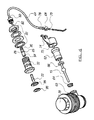
- FIG. 4 illustrates the components of an assembly in accordance with the invention.
- the drain assembly has a connector 60 which receives therein a connector 62 and within which are provided elongate member 15 and sealing members 64, 66.
- the elongate member 15 is a standard rod for actuating the closure but it is gripped via collar 68 which is tightened thereon by screw 70.
- a restraining collar 72 which has a location formation 74 into which the end of member 44 is inserted and retained. The end 78 of the member is attached to the collar 68. The opposing end 80 of the member 44 passes to the assembly located in the overflow.
- the assembly includes a series of seals and tightening means 82 which engage a housing 32 and in turn serve to attach and seal the assembly to the sink or bath at the overflow.
- a connector 86 Passing through the housing 32 is provided a connector 86 which includes sealing o-rings 88 thereon.
- the connector 86 receives the ball 92 of the member end 80 and at the other end 94, is connected to be part of the actuating means 22 which is located to protrude from the overflow and allow actuation of the same by a person pressing on the plate 96 attached to the end 98 of the actuating means.
Landscapes
- Engineering & Computer Science (AREA)
- Mechanical Engineering (AREA)
- Environmental & Geological Engineering (AREA)
- Health & Medical Sciences (AREA)
- Life Sciences & Earth Sciences (AREA)
- Hydrology & Water Resources (AREA)
- Public Health (AREA)
- Water Supply & Treatment (AREA)
- Sink And Installation For Waste Water (AREA)
Applications Claiming Priority (1)
| Application Number | Priority Date | Filing Date | Title |
|---|---|---|---|
| GB0903781A GB0903781D0 (en) | 2009-03-05 | 2009-03-05 | Combined waste, overflow movement device |
Publications (1)
| Publication Number | Publication Date |
|---|---|
| EP2226435A1 true EP2226435A1 (fr) | 2010-09-08 |
Family
ID=40580667
Family Applications (1)
| Application Number | Title | Priority Date | Filing Date |
|---|---|---|---|
| EP10250377A Withdrawn EP2226435A1 (fr) | 2009-03-05 | 2010-03-03 | Überlauf- und Ablaufsteuerung für Badewanne |
Country Status (2)
| Country | Link |
|---|---|
| EP (1) | EP2226435A1 (fr) |
| GB (1) | GB0903781D0 (fr) |
Cited By (3)
| Publication number | Priority date | Publication date | Assignee | Title |
|---|---|---|---|---|
| WO2013026010A3 (fr) * | 2011-08-18 | 2013-07-25 | Kohler Co. | Système de vidange |
| WO2013184095A1 (fr) * | 2012-06-05 | 2013-12-12 | Vito Laera | Commutateur de trop-plein |
| CN109610570A (zh) * | 2018-10-16 | 2019-04-12 | 宁波德远洁具有限公司 | 去水器组件及其工作方法 |
Citations (4)
| Publication number | Priority date | Publication date | Assignee | Title |
|---|---|---|---|---|
| US4796310A (en) | 1986-07-14 | 1989-01-10 | Kohler Co. | Bathtub drain valve control and overflow plate |
| FR2624152A1 (fr) | 1987-12-04 | 1989-06-09 | Dubosc Landowski Scp | Appareil sanitaire a dispositif d'evacuation integre, de faible encombrement vertical, son procede de moulage et moule pour la mise en oeuvre du procede |
| US6154898A (en) | 1999-05-19 | 2000-12-05 | Wcm Industries, Inc. | Wastewater drain control for fluid compartments |
| EP1703027A1 (fr) | 2005-03-17 | 2006-09-20 | Geberit Technik Ag | Dispositif pour activer le clapet d'écoulement d'articles sanitaires et en particulier une baignoire |
-
2009
- 2009-03-05 GB GB0903781A patent/GB0903781D0/en not_active Ceased
-
2010
- 2010-03-03 EP EP10250377A patent/EP2226435A1/fr not_active Withdrawn
Patent Citations (4)
| Publication number | Priority date | Publication date | Assignee | Title |
|---|---|---|---|---|
| US4796310A (en) | 1986-07-14 | 1989-01-10 | Kohler Co. | Bathtub drain valve control and overflow plate |
| FR2624152A1 (fr) | 1987-12-04 | 1989-06-09 | Dubosc Landowski Scp | Appareil sanitaire a dispositif d'evacuation integre, de faible encombrement vertical, son procede de moulage et moule pour la mise en oeuvre du procede |
| US6154898A (en) | 1999-05-19 | 2000-12-05 | Wcm Industries, Inc. | Wastewater drain control for fluid compartments |
| EP1703027A1 (fr) | 2005-03-17 | 2006-09-20 | Geberit Technik Ag | Dispositif pour activer le clapet d'écoulement d'articles sanitaires et en particulier une baignoire |
Cited By (7)
| Publication number | Priority date | Publication date | Assignee | Title |
|---|---|---|---|---|
| WO2013026010A3 (fr) * | 2011-08-18 | 2013-07-25 | Kohler Co. | Système de vidange |
| US9062441B2 (en) | 2011-08-18 | 2015-06-23 | Kohler Co. | Cable overload device |
| US9181686B2 (en) | 2011-08-18 | 2015-11-10 | Kohler Co. | Replaceable trim kit |
| US9260846B2 (en) | 2011-08-18 | 2016-02-16 | Kohler Co. | Drain control assembly |
| US9816258B2 (en) | 2011-08-18 | 2017-11-14 | Kohler Co. | Drain control assembly |
| WO2013184095A1 (fr) * | 2012-06-05 | 2013-12-12 | Vito Laera | Commutateur de trop-plein |
| CN109610570A (zh) * | 2018-10-16 | 2019-04-12 | 宁波德远洁具有限公司 | 去水器组件及其工作方法 |
Also Published As
| Publication number | Publication date |
|---|---|
| GB0903781D0 (en) | 2009-04-15 |
Similar Documents
| Publication | Publication Date | Title |
|---|---|---|
| CA2556382C (fr) | Dispositif d'obturation de tuyau d'evacuation de baignoire | |
| CA2675721C (fr) | Tuyau d'evacuation par cable | |
| CA2448464C (fr) | Dispositif electromagnetique de fermeture de tuyau d'evacuation de baignoire | |
| EP2226435A1 (fr) | Überlauf- und Ablaufsteuerung für Badewanne | |
| EP2325407A1 (fr) | Soupape de dérivation | |
| US20110167555A1 (en) | Closing and securing assembly for a bathtub and/or shower basin | |
| US20070044231A1 (en) | A motor activated bathtub drain closure | |
| EP3296613A1 (fr) | Robinet pour fluide sous pression | |
| US7810786B2 (en) | Gate valve actuator | |
| JP2916744B2 (ja) | 排水栓装置 | |
| US5724908A (en) | Remote controlled boat drain valve | |
| US20100139784A1 (en) | Float-controlled water inflow switching device for water pump | |
| EP2006457A1 (fr) | Valve d'écoulement mobile pour sortie d'évacuation | |
| US20030196258A1 (en) | Automatic toilet bowl overflow prevention device | |
| TWI691634B (zh) | 多功能地板排水器 | |
| KR200434582Y1 (ko) | 좌변기용 전동식 물내림 장치 | |
| DE3260671D1 (en) | Toilet flush tank | |
| JP2006112092A (ja) | フラッシュバルブの駆動装置 | |
| CN211037173U (zh) | 一种水槽下水器排水口的开合控制机构 | |
| JP6631779B2 (ja) | 遠隔操作式排水栓装置 | |
| PL349803A1 (en) | Quick-discharge valve control device for lavatory bowl flushing cisterns | |
| EP1336692B1 (fr) | Cuve de déchets pour toilette mobile et système de toilette mobile | |
| KR200221928Y1 (ko) | 하수 및 악취역류 방지장치 | |
| US20160102449A1 (en) | Flushable Campsite Toilet | |
| KR101950886B1 (ko) | 냄새차단 기능을 갖는 폽업 |
Legal Events
| Date | Code | Title | Description |
|---|---|---|---|
| PUAI | Public reference made under article 153(3) epc to a published international application that has entered the european phase |
Free format text: ORIGINAL CODE: 0009012 |
|
| AK | Designated contracting states |
Kind code of ref document: A1 Designated state(s): AT BE BG CH CY CZ DE DK EE ES FI FR GB GR HR HU IE IS IT LI LT LU LV MC MK MT NL NO PL PT RO SE SI SK SM TR |
|
| AX | Request for extension of the european patent |
Extension state: AL BA ME RS |
|
| STAA | Information on the status of an ep patent application or granted ep patent |
Free format text: STATUS: THE APPLICATION IS DEEMED TO BE WITHDRAWN |
|
| 18D | Application deemed to be withdrawn |
Effective date: 20110309 |