EP2226134A2 - Verfahren zur Herstellung einer Tragfläche - Google Patents
Verfahren zur Herstellung einer Tragfläche Download PDFInfo
- Publication number
- EP2226134A2 EP2226134A2 EP10153068A EP10153068A EP2226134A2 EP 2226134 A2 EP2226134 A2 EP 2226134A2 EP 10153068 A EP10153068 A EP 10153068A EP 10153068 A EP10153068 A EP 10153068A EP 2226134 A2 EP2226134 A2 EP 2226134A2
- Authority
- EP
- European Patent Office
- Prior art keywords
- metallic
- aerofoil
- panels
- joined
- aerofoil structure
- Prior art date
- Legal status (The legal status is an assumption and is not a legal conclusion. Google has not performed a legal analysis and makes no representation as to the accuracy of the status listed.)
- Withdrawn
Links
Images

Classifications
-
- B—PERFORMING OPERATIONS; TRANSPORTING
- B21—MECHANICAL METAL-WORKING WITHOUT ESSENTIALLY REMOVING MATERIAL; PUNCHING METAL
- B21D—WORKING OR PROCESSING OF SHEET METAL OR METAL TUBES, RODS OR PROFILES WITHOUT ESSENTIALLY REMOVING MATERIAL; PUNCHING METAL
- B21D53/00—Making other particular articles
- B21D53/78—Making other particular articles propeller blades; turbine blades
-
- B—PERFORMING OPERATIONS; TRANSPORTING
- B21—MECHANICAL METAL-WORKING WITHOUT ESSENTIALLY REMOVING MATERIAL; PUNCHING METAL
- B21D—WORKING OR PROCESSING OF SHEET METAL OR METAL TUBES, RODS OR PROFILES WITHOUT ESSENTIALLY REMOVING MATERIAL; PUNCHING METAL
- B21D26/00—Shaping without cutting otherwise than using rigid devices or tools or yieldable or resilient pads, i.e. applying fluid pressure or magnetic forces
- B21D26/02—Shaping without cutting otherwise than using rigid devices or tools or yieldable or resilient pads, i.e. applying fluid pressure or magnetic forces by applying fluid pressure
- B21D26/053—Shaping without cutting otherwise than using rigid devices or tools or yieldable or resilient pads, i.e. applying fluid pressure or magnetic forces by applying fluid pressure characterised by the material of the blanks
- B21D26/055—Blanks having super-plastic properties
-
- B—PERFORMING OPERATIONS; TRANSPORTING
- B23—MACHINE TOOLS; METAL-WORKING NOT OTHERWISE PROVIDED FOR
- B23K—SOLDERING OR UNSOLDERING; WELDING; CLADDING OR PLATING BY SOLDERING OR WELDING; CUTTING BY APPLYING HEAT LOCALLY, e.g. FLAME CUTTING; WORKING BY LASER BEAM
- B23K20/00—Non-electric welding by applying impact or other pressure, with or without the application of heat, e.g. cladding or plating
- B23K20/16—Non-electric welding by applying impact or other pressure, with or without the application of heat, e.g. cladding or plating with interposition of special material to facilitate connection of the parts, e.g. material for absorbing or producing gas
-
- B—PERFORMING OPERATIONS; TRANSPORTING
- B23—MACHINE TOOLS; METAL-WORKING NOT OTHERWISE PROVIDED FOR
- B23P—METAL-WORKING NOT OTHERWISE PROVIDED FOR; COMBINED OPERATIONS; UNIVERSAL MACHINE TOOLS
- B23P15/00—Making specific metal objects by operations not covered by a single other subclass or a group in this subclass
- B23P15/04—Making specific metal objects by operations not covered by a single other subclass or a group in this subclass turbine or like blades from several pieces
-
- F—MECHANICAL ENGINEERING; LIGHTING; HEATING; WEAPONS; BLASTING
- F01—MACHINES OR ENGINES IN GENERAL; ENGINE PLANTS IN GENERAL; STEAM ENGINES
- F01D—NON-POSITIVE DISPLACEMENT MACHINES OR ENGINES, e.g. STEAM TURBINES
- F01D5/00—Blades; Blade-carrying members; Heating, heat-insulating, cooling or antivibration means on the blades or the members
- F01D5/12—Blades
- F01D5/14—Form or construction
- F01D5/147—Construction, i.e. structural features, e.g. of weight-saving hollow blades
-
- F—MECHANICAL ENGINEERING; LIGHTING; HEATING; WEAPONS; BLASTING
- F01—MACHINES OR ENGINES IN GENERAL; ENGINE PLANTS IN GENERAL; STEAM ENGINES
- F01D—NON-POSITIVE DISPLACEMENT MACHINES OR ENGINES, e.g. STEAM TURBINES
- F01D5/00—Blades; Blade-carrying members; Heating, heat-insulating, cooling or antivibration means on the blades or the members
- F01D5/12—Blades
- F01D5/14—Form or construction
- F01D5/18—Hollow blades, i.e. blades with cooling or heating channels or cavities; Heating, heat-insulating or cooling means on blades
-
- B—PERFORMING OPERATIONS; TRANSPORTING
- B23—MACHINE TOOLS; METAL-WORKING NOT OTHERWISE PROVIDED FOR
- B23K—SOLDERING OR UNSOLDERING; WELDING; CLADDING OR PLATING BY SOLDERING OR WELDING; CUTTING BY APPLYING HEAT LOCALLY, e.g. FLAME CUTTING; WORKING BY LASER BEAM
- B23K2101/00—Articles made by soldering, welding or cutting
- B23K2101/001—Turbines
-
- F—MECHANICAL ENGINEERING; LIGHTING; HEATING; WEAPONS; BLASTING
- F05—INDEXING SCHEMES RELATING TO ENGINES OR PUMPS IN VARIOUS SUBCLASSES OF CLASSES F01-F04
- F05D—INDEXING SCHEME FOR ASPECTS RELATING TO NON-POSITIVE-DISPLACEMENT MACHINES OR ENGINES, GAS-TURBINES OR JET-PROPULSION PLANTS
- F05D2230/00—Manufacture
- F05D2230/20—Manufacture essentially without removing material
- F05D2230/23—Manufacture essentially without removing material by permanently joining parts together
- F05D2230/232—Manufacture essentially without removing material by permanently joining parts together by welding
- F05D2230/236—Diffusion bonding
-
- Y—GENERAL TAGGING OF NEW TECHNOLOGICAL DEVELOPMENTS; GENERAL TAGGING OF CROSS-SECTIONAL TECHNOLOGIES SPANNING OVER SEVERAL SECTIONS OF THE IPC; TECHNICAL SUBJECTS COVERED BY FORMER USPC CROSS-REFERENCE ART COLLECTIONS [XRACs] AND DIGESTS
- Y02—TECHNOLOGIES OR APPLICATIONS FOR MITIGATION OR ADAPTATION AGAINST CLIMATE CHANGE
- Y02T—CLIMATE CHANGE MITIGATION TECHNOLOGIES RELATED TO TRANSPORTATION
- Y02T50/00—Aeronautics or air transport
- Y02T50/60—Efficient propulsion technologies, e.g. for aircraft
-
- Y—GENERAL TAGGING OF NEW TECHNOLOGICAL DEVELOPMENTS; GENERAL TAGGING OF CROSS-SECTIONAL TECHNOLOGIES SPANNING OVER SEVERAL SECTIONS OF THE IPC; TECHNICAL SUBJECTS COVERED BY FORMER USPC CROSS-REFERENCE ART COLLECTIONS [XRACs] AND DIGESTS
- Y10—TECHNICAL SUBJECTS COVERED BY FORMER USPC
- Y10T—TECHNICAL SUBJECTS COVERED BY FORMER US CLASSIFICATION
- Y10T29/00—Metal working
- Y10T29/49—Method of mechanical manufacture
- Y10T29/49316—Impeller making
- Y10T29/49318—Repairing or disassembling
-
- Y—GENERAL TAGGING OF NEW TECHNOLOGICAL DEVELOPMENTS; GENERAL TAGGING OF CROSS-SECTIONAL TECHNOLOGIES SPANNING OVER SEVERAL SECTIONS OF THE IPC; TECHNICAL SUBJECTS COVERED BY FORMER USPC CROSS-REFERENCE ART COLLECTIONS [XRACs] AND DIGESTS
- Y10—TECHNICAL SUBJECTS COVERED BY FORMER USPC
- Y10T—TECHNICAL SUBJECTS COVERED BY FORMER US CLASSIFICATION
- Y10T29/00—Metal working
- Y10T29/49—Method of mechanical manufacture
- Y10T29/49316—Impeller making
- Y10T29/49336—Blade making
- Y10T29/49337—Composite blade
-
- Y—GENERAL TAGGING OF NEW TECHNOLOGICAL DEVELOPMENTS; GENERAL TAGGING OF CROSS-SECTIONAL TECHNOLOGIES SPANNING OVER SEVERAL SECTIONS OF THE IPC; TECHNICAL SUBJECTS COVERED BY FORMER USPC CROSS-REFERENCE ART COLLECTIONS [XRACs] AND DIGESTS
- Y10—TECHNICAL SUBJECTS COVERED BY FORMER USPC
- Y10T—TECHNICAL SUBJECTS COVERED BY FORMER US CLASSIFICATION
- Y10T29/00—Metal working
- Y10T29/49—Method of mechanical manufacture
- Y10T29/49316—Impeller making
- Y10T29/49336—Blade making
- Y10T29/49339—Hollow blade
- Y10T29/49341—Hollow blade with cooling passage
- Y10T29/49343—Passage contains tubular insert
Definitions
- This invention relates to an aerofoil structure and method of manufacturing an aerofoil structure, and particularly but not exclusively to a substantially hollow aerofoil structure which is superplastically formed.
- hollow metallic aerofoils for example to be used as blades in a jet engine, and in particular fan blades for a turbomachine, by superplastic forming and diffusion bonding metallic panels, the panels forming pressure and suction surfaces of the blade. These blades are generally referred to as wide-chord fan blades.
- the metallic panels may include elementary metal, metal alloys and metal matrix composites. At least one of the metallic panels must be capable of superplastic extensions. In one known process the surfaces of the panels to be joined are cleaned, and at least one surface of one or more of the panels is coated in preselected areas with a stop-off material to prevent diffusion bonding.
- the panels are arranged in a stack and the edges of the panels are welded together, except where a pipe is welded to the panels, to form an assembly.
- the pipe enables a vacuum, or inert gas pressure, to be applied to the interior of the assembly.
- the assembly is placed in an autoclave and heated so as to "bake out” the binder from the material to prevent diffusion bonding.
- the assembly is then evacuated, using the pipe, and the pipe is sealed.
- the sealed assembly is placed in a pressure vessel and is heated and pressed to diffusion bond the panels together to form an integral structure. Diffusion bonding occurs when two mating surfaces are pressed together under temperature, time and pressure conditions that allow atom interchange across the interface.
- the first pipe is removed and a second pipe is fitted to the diffusion bonded assembly at the position where the first pipe was located.
- the integral structure is located between appropriately shaped dies and is placed within a rig.
- the integral structure and dies are heated and pressurised fluid is supplied through the second pipe into the interior of the integral structure to cause at least one of the panels to be superplastically formed to produce an article matching the shape of the dies.
- Figure 1 illustrates a known method of manufacturing an aerofoil structure.
- a metallic sheet 2 made from, for example titanium, is provided for forming the aerofoil structure.
- the sheet 2 is forged so as to produce two sections 4 of the sheet which are thicker than the main body of the sheet 2. This may be achieved by upset forging, wherein the length of the sheet is reduced in order to obtain the desired increase in cross-section or by drawing the sheet so as to increase the length and reduce the thickness of the main body of the sheet.
- the sheet 2 may be machine finished prior to the forging and/or splitting/dividing process.
- the forged sheet 2 is divided along an inclined plane 6 extending in a span-wise direction, so as to produce two substantially identical panels 8 and 10.
- the panels 8 and 10 need not be identical and alternative configurations may be used in order to provide desired properties for the resulting aerofoil e.g. the panels may be of differing thickness.
- the sheet 2 may be divided into the two panels 8 and 10 by way of any known technique which may be suitable for cutting the required width of the aerofoil, for example by using a band saw.
- channels may be machined inboard of the elements 4 to allow the band saw to enter the workpiece, as described in patent application GB2306353 (see figure 2 ).
- the resulting panels 8 and 10 taper from the section 4 to the tip end of the panel.
- the two panels 8 and 10 are then assembled so that their uncut exterior surfaces (which have been machine finished) are facing each other.
- a membrane 12 may be positioned between the panels 8 and 10.
- the assembly may then be diffusion bonded and superplastically formed in order to produce the desired external shape of the aerofoil.
- the sections 4 combine to form the root of the aerofoil which serves in use to attach the aerofoil, for example, to the hub of the rotor.
- This method of manufacturing an aerofoil structure has certain disadvantages attributable to the forging process which is necessary in order to obtain the sections 4 that form the root of the aerofoil once the two panels 8 and 10 are assembled.
- the thickness of the root is limited by the forging process such that it is often not possible to produce a root with the required thickness for the application.
- the root and aerofoil structures experience different working loads and environments, it is desirable for these structures to have different material properties. This is not possible in the prior art method.
- GB2306353 does disclose a further step for increasing the thickness of the root, where additional blocks are joined to the root element.
- the root element still comprises the material of the aerofoil structure and thus it is still not possible to obtain substantially different properties for the root and aerofoil structures.
- EP1605135 discloses a method of making and joining an aerofoil and root wherein an aerofoil structure is prefabricated and then joined to a root element by means of electron beam welding or linear friction welding. This method requires the root element and also the joining surface of the aerofoil structure to be machined prior to joining. This therefore adds additional steps to the process which increases costs and manufacturing time.
- a method of manufacturing an aerofoil structure capable of being diffusion bonded and superplastically formed to create a substantially hollow cavity within the aerofoil structure, the method comprising: providing a metallic plate for forming the aerofoil structure; joining mounting elements to opposing end surfaces of said metallic plate; dividing said plate along a plane extending substantially in a span-wise direction so as to produce two metallic panels each with one of said mounting elements joined thereto; assembling the two metallic panels so that the surfaces of the panels opposite to the surfaces which have been divided are facing each other; and joining the two metallic panels to one another to form the aerofoil structure; wherein the mounting elements are joined to one another to form the root of the aerofoil.
- the metallic plate and mounting element and/or the two metallic panels may be joined by any suitable method such as one or more of: diffusion bonding, friction stir welding, linear friction welding, electron beam welding, or press bonding.
- the mounting elements may be aligned with the metallic plate so as to form a substantially uniform joining surface on the divided panels.
- the mounting elements may be made from a different metallic material from that of the metallic plate.
- a method of manufacturing an aerofoil structure capable of being diffusion bonded and superplastically formed to create a substantially hollow cavity within the aerofoil structure, the method comprising: providing a metallic plate for forming the aerofoil structure; dividing said plate along a plane extending substantially in a span-wise direction so as to produce two metallic sheets; joining mounting elements to one end surface of each of said two metallic sheets to form two metallic panels; assembling the two metallic panels so that the surfaces of the panels opposite to the surfaces which have been divided are facing each other; and joining the two metallic panels to one another to form the aerofoil structure; wherein the mounting elements are joined to one another to form the root of the aerofoil.
- the metallic sheet and mounting element and/or the metallic panels may be joined by any suitable method such as one or more of: diffusion bonding, friction stir welding, linear friction welding, electron beam welding, or press bonding.
- the mounting elements may be aligned with the metallic sheets so as to form a substantially uniform joining surface.
- the mounting elements may be made from a different metallic material from that of the metallic sheets.
- the root of the aerofoil may be thicker than the thickness of the joined metallic sheets.
- a substantially hollow aerofoil structure comprising two metallic panels, each metallic panel comprising a metallic sheet joined to a mounting element; the metallic panels being joined together so that the metallic sheets form the aerofoil and the mounting elements form the root of the aerofoil.
- the mounting elements may be aligned with the metallic sheets so as to form a substantially uniform joining surface.
- the root of the aerofoil may be thicker than the thickness of the joined metallic sheets.
- the metallic sheet and mounting element and/or the metallic panels may be joined by one or more of: diffusion bonding, friction stir welding, electron beam welding, or press bonding.
- the joined metallic panels may be superplastically formed.
- the aerofoil structure may further comprise a membrane sheet between the two metallic panels.
- the mounting elements may be made from a different metallic material from that of the metallic sheet.
- Figure 2 illustrates a method of manufacturing an aerofoil structure in accordance with a first embodiment of the invention.
- a metallic sheet 20 is provided for forming the aerofoil structure.
- sheet 20 is shorter than the required span of the aerofoil.
- mounting elements 14 may comprise metallic blocks which are joined to either end of sheet 20.
- the mounting elements 14 may be joined to the sheet 20 by any suitable joining technique, in particular diffusion bonding, friction stir welding, linear friction welding, electron beam welding or press bonding may be used.
- the elements 14 are of greater thickness than the sheet 20 and the edge of one of the elements 14 is aligned substantially parallel with one side of the sheet 20 and the edge of the other element 14 is aligned substantially parallel with the other side of the sheet 20.
- the substantially parallel surfaces created by the aligned edge of the elements 14 and the sheet 2 may be machine finished to ensure a uniform surface.
- the forged sheet 20 is then divided along an inclined plane 18 extending in a span-wise direction, so as to produce two substantially identical panels 22 and 24.
- the panels 22 and 24 need not be identical and alternative configurations may be used in order to provide desired properties for the resulting aerofoil e.g. the panels may be of differing thickness.
- the panels 22 and 24 may form the pressure and suction surfaces of a blade for a turbomachine.
- the sheet 20 may be divided into the two panels 22 and 24 by way of any known technique which may be suitable for cutting the required width of the aerofoil, for example by using a band saw. To facilitate the cutting process, channels 16 may be machined inboard of the elements 14 to allow the band saw to enter the workpiece.
- the two panels 22 and 24 are then assembled so that their uncut exterior surfaces (which have previously been machine finished) are facing each other.
- a membrane may be positioned between the panels 22 and 24.
- the assembly may then be diffusion bonded and superplastically formed in order to produce the desired external shape of the aerofoil.
- the elements 14 combine to form the root of the aerofoil which serves in use to attach the aerofoil, for example, to the hub of the rotor.
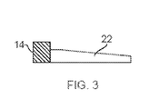
- Figure 3 illustrates a method of manufacturing an aerofoil structure in accordance with a second embodiment of the invention.
- This embodiment is substantially as per the first embodiment, however the mounting element 14 is joined to the panel 22 or 24 after the sheet 20 has been divided into the two panels. Joining the element 14 after dividing the sheet 20, may simplify the dividing process and remove the need for the machining of channels 16.
- the elements 14 may be of any shape and thickness required by the application of the aerofoil.
- the elements 14 may advantageously be made from a material with different properties to that of the aerofoil itself. Thus the material may be selected specifically for the requirements of the root. This in turn gives increased flexibility in the choice of material used for the aerofoil as it is no longer necessary to compromise for the requirements of both the root and aerofoil.
- a material can be chosen with the required ductility, crack propagation resistance, and other characteristics desired.
- Any combination of materials for the root and aerofoil may be used which can be adequately joined and may include dissimilar elementary metals, metal alloys (for example, different grades of Titanium) and metal matrix composites.
- the invention also facilitates low cavity or through cavity designs in which there is no membrane to form an internal structure. The percentage hollowness of such a blade is therefore increased which in turn reduces the weight and blade-off energy of the blade.
- the invention requires a single joining process along the perimeter of the aerofoil, whereas the method described in EP1605135 the aerofoil panels must first be joined and then the root element joined to the aerofoil. This also has added benefits in reducing machining requirements.
Applications Claiming Priority (1)
| Application Number | Priority Date | Filing Date | Title |
|---|---|---|---|
| GBGB0903614.6A GB0903614D0 (en) | 2009-03-04 | 2009-03-04 | Method of manufacturing an aerofoil |
Publications (2)
| Publication Number | Publication Date |
|---|---|
| EP2226134A2 true EP2226134A2 (de) | 2010-09-08 |
| EP2226134A3 EP2226134A3 (de) | 2014-01-08 |
Family
ID=40566057
Family Applications (1)
| Application Number | Title | Priority Date | Filing Date |
|---|---|---|---|
| EP10153068.1A Withdrawn EP2226134A3 (de) | 2009-03-04 | 2010-02-09 | Verfahren zur Herstellung einer Tragfläche |
Country Status (3)
| Country | Link |
|---|---|
| US (1) | US8496440B2 (de) |
| EP (1) | EP2226134A3 (de) |
| GB (1) | GB0903614D0 (de) |
Families Citing this family (5)
| Publication number | Priority date | Publication date | Assignee | Title |
|---|---|---|---|---|
| US7762447B2 (en) * | 2008-03-20 | 2010-07-27 | Ut-Battelle, Llc | Multiple pass and multiple layer friction stir welding and material enhancement processes |
| JP5802972B2 (ja) * | 2011-07-11 | 2015-11-04 | 大同特殊鋼株式会社 | タービンブレードの製造方法 |
| JP5853451B2 (ja) * | 2011-07-11 | 2016-02-09 | 大同特殊鋼株式会社 | タービンブレードの鍛造成形方法 |
| FR2997884B3 (fr) * | 2012-11-09 | 2015-06-26 | Mecachrome France | Procede et dispositif de fabrication d'aubes de turbines. |
| US20170074116A1 (en) * | 2014-07-17 | 2017-03-16 | United Technologies Corporation | Method of creating heat transfer features in high temperature alloys |
Citations (4)
| Publication number | Priority date | Publication date | Assignee | Title |
|---|---|---|---|---|
| GB2306353A (en) | 1995-10-28 | 1997-05-07 | Rolls Royce Plc | A method of manufacturing a blade |
| EP1447524A2 (de) * | 2003-02-13 | 2004-08-18 | Alstom Technology Ltd | Hybrid-Schaufel für thermische Turbomaschinen |
| EP1605135A2 (de) | 2004-06-10 | 2005-12-14 | Rolls-Royce Plc | Herstellungsmethode und Zusammenbau von Turbinenblatt und Turbinenblattfuss |
| EP1905954A1 (de) * | 2006-09-20 | 2008-04-02 | Siemens Aktiengesellschaft | Turbinenschaufel |
Family Cites Families (10)
| Publication number | Priority date | Publication date | Assignee | Title |
|---|---|---|---|---|
| US4364160A (en) | 1980-11-03 | 1982-12-21 | General Electric Company | Method of fabricating a hollow article |
| US5429877A (en) * | 1993-10-20 | 1995-07-04 | The United States Of America As Represented By The Secretary Of The Air Force | Internally reinforced hollow titanium alloy components |
| US5687900A (en) * | 1995-03-28 | 1997-11-18 | Mcdonnell Douglas Corporation | Structural panel having a predetermined shape and an associated method for superplastically forming and diffusion bonding the structural panel |
| US5692881A (en) * | 1995-06-08 | 1997-12-02 | United Technologies Corporation | Hollow metallic structure and method of manufacture |
| GB0022531D0 (en) * | 2000-09-14 | 2000-11-01 | Rolls Royce Plc | A method of manufacturing an article by diffusion bonding |
| GB0203955D0 (en) | 2002-02-20 | 2002-04-03 | Rolls Royce Plc | A method of manufacturing an article by diffusion bonding and super[lastic forming |
| US6705011B1 (en) * | 2003-02-10 | 2004-03-16 | United Technologies Corporation | Turbine element manufacture |
| FR2855439B1 (fr) * | 2003-05-27 | 2006-07-14 | Snecma Moteurs | Procede de fabrication d'une aube creuse pour turbomachine. |
| GB0318937D0 (en) * | 2003-08-13 | 2003-09-17 | Rolls Royce Plc | A method of manufacturing an article by diffusion bonding and superplastic forming |
| FR2867095B1 (fr) * | 2004-03-03 | 2007-04-20 | Snecma Moteurs | Procede de fabrication d'une aube creuse pour turbomachine. |
-
2009
- 2009-03-04 GB GBGB0903614.6A patent/GB0903614D0/en not_active Ceased
-
2010
- 2010-02-09 EP EP10153068.1A patent/EP2226134A3/de not_active Withdrawn
- 2010-02-09 US US12/702,920 patent/US8496440B2/en active Active
Patent Citations (4)
| Publication number | Priority date | Publication date | Assignee | Title |
|---|---|---|---|---|
| GB2306353A (en) | 1995-10-28 | 1997-05-07 | Rolls Royce Plc | A method of manufacturing a blade |
| EP1447524A2 (de) * | 2003-02-13 | 2004-08-18 | Alstom Technology Ltd | Hybrid-Schaufel für thermische Turbomaschinen |
| EP1605135A2 (de) | 2004-06-10 | 2005-12-14 | Rolls-Royce Plc | Herstellungsmethode und Zusammenbau von Turbinenblatt und Turbinenblattfuss |
| EP1905954A1 (de) * | 2006-09-20 | 2008-04-02 | Siemens Aktiengesellschaft | Turbinenschaufel |
Also Published As
| Publication number | Publication date |
|---|---|
| GB0903614D0 (en) | 2009-04-08 |
| EP2226134A3 (de) | 2014-01-08 |
| US8496440B2 (en) | 2013-07-30 |
| US20100226781A1 (en) | 2010-09-09 |
Similar Documents
| Publication | Publication Date | Title |
|---|---|---|
| EP2226133B1 (de) | Verfahren zur Herstellung einer Tragfläche | |
| US6467168B2 (en) | Method of manufacturing an article by diffusion bonding and superplastic forming | |
| US8782887B2 (en) | Method for producing a metal insert to protect a leading edge made of a composite material | |
| EP1508400B1 (de) | Verfahren zur Herstellung eines Gegenstandes durch Diffusionsschweissen und superplastisches Verformen | |
| CN103328150B (zh) | 制造金属增强件的方法 | |
| US9120189B2 (en) | Method of making a piece of metal reinforcement | |
| US6739049B2 (en) | Method of manufacturing an article by diffusion bonding and superplastic forming | |
| JP2015520033A (ja) | 複合物でできた前縁を保護するためのインサートを備えた金属補強材を形成するための方法 | |
| US8496440B2 (en) | Method of manufacturing an aerofoil | |
| EP2368651A1 (de) | Verfahren zur herstellung einer hohlen lüfterschaufel | |
| US8661669B2 (en) | Method of making and joining an aerofoil and root | |
| US8439647B2 (en) | Cooled turbine airfoil fabricated from sheet material | |
| EP1600251B1 (de) | Verfahren zum Doppelschmieden eines Artikels mit nahezu Fertigmassen | |
| US6802122B2 (en) | Method of manufacturing an article | |
| EP2213391A2 (de) | Verfahren zur Verbindung von Materialplatten zum Bilden einer Struktur | |
| EP2243626B1 (de) | Verfahren zur herstellung einer tragfläche | |
| EP2223767A1 (de) | Verfahren zur Herstellung einer Schaufel | |
| EP2233223B1 (de) | Verfahren zum Bilden einer inneren Struktur in einer Hohlkomponente | |
| EP2469027B1 (de) | Diffusionsgeschweißte und superplastisch geformte Turbomaschinenschaufel | |
| EP2772613A1 (de) | Turbomaschinenschaufel und zugehöriges Herstellungsverfahren |
Legal Events
| Date | Code | Title | Description |
|---|---|---|---|
| PUAI | Public reference made under article 153(3) epc to a published international application that has entered the european phase |
Free format text: ORIGINAL CODE: 0009012 |
|
| AK | Designated contracting states |
Kind code of ref document: A2 Designated state(s): AT BE BG CH CY CZ DE DK EE ES FI FR GB GR HR HU IE IS IT LI LT LU LV MC MK MT NL NO PL PT RO SE SI SK SM TR |
|
| AX | Request for extension of the european patent |
Extension state: AL BA RS |
|
| PUAL | Search report despatched |
Free format text: ORIGINAL CODE: 0009013 |
|
| AK | Designated contracting states |
Kind code of ref document: A3 Designated state(s): AT BE BG CH CY CZ DE DK EE ES FI FR GB GR HR HU IE IS IT LI LT LU LV MC MK MT NL NO PL PT RO SE SI SK SM TR |
|
| AX | Request for extension of the european patent |
Extension state: AL BA RS |
|
| RIC1 | Information provided on ipc code assigned before grant |
Ipc: B23P 15/04 20060101ALI20131203BHEP Ipc: B21D 53/78 20060101AFI20131203BHEP Ipc: B21D 26/02 20110101ALI20131203BHEP Ipc: F01D 5/18 20060101ALI20131203BHEP |
|
| 17P | Request for examination filed |
Effective date: 20140708 |
|
| RBV | Designated contracting states (corrected) |
Designated state(s): AT BE BG CH CY CZ DE DK EE ES FI FR GB GR HR HU IE IS IT LI LT LU LV MC MK MT NL NO PL PT RO SE SI SK SM TR |
|
| RAP1 | Party data changed (applicant data changed or rights of an application transferred) |
Owner name: ROLLS-ROYCE PLC |
|
| 17Q | First examination report despatched |
Effective date: 20151123 |
|
| STAA | Information on the status of an ep patent application or granted ep patent |
Free format text: STATUS: THE APPLICATION IS DEEMED TO BE WITHDRAWN |
|
| 18D | Application deemed to be withdrawn |
Effective date: 20160604 |