EP2226027A1 - Surgical access devices and methods providing seal movement in predefined paths - Google Patents
Surgical access devices and methods providing seal movement in predefined paths Download PDFInfo
- Publication number
- EP2226027A1 EP2226027A1 EP10250406A EP10250406A EP2226027A1 EP 2226027 A1 EP2226027 A1 EP 2226027A1 EP 10250406 A EP10250406 A EP 10250406A EP 10250406 A EP10250406 A EP 10250406A EP 2226027 A1 EP2226027 A1 EP 2226027A1
- Authority
- EP
- European Patent Office
- Prior art keywords
- housing
- sealing elements
- access device
- sealing
- surgical access
- Prior art date
- Legal status (The legal status is an assumption and is not a legal conclusion. Google has not performed a legal analysis and makes no representation as to the accuracy of the status listed.)
- Withdrawn
Links
Images


Classifications
-
- A—HUMAN NECESSITIES
- A61—MEDICAL OR VETERINARY SCIENCE; HYGIENE
- A61B—DIAGNOSIS; SURGERY; IDENTIFICATION
- A61B17/00—Surgical instruments, devices or methods, e.g. tourniquets
- A61B17/34—Trocars; Puncturing needles
- A61B17/3417—Details of tips or shafts, e.g. grooves, expandable, bendable; Multiple coaxial sliding cannulas, e.g. for dilating
- A61B17/3421—Cannulas
- A61B17/3423—Access ports, e.g. toroid shape introducers for instruments or hands
-
- A—HUMAN NECESSITIES
- A61—MEDICAL OR VETERINARY SCIENCE; HYGIENE
- A61B—DIAGNOSIS; SURGERY; IDENTIFICATION
- A61B17/00—Surgical instruments, devices or methods, e.g. tourniquets
- A61B17/34—Trocars; Puncturing needles
- A61B17/3462—Trocars; Puncturing needles with means for changing the diameter or the orientation of the entrance port of the cannula, e.g. for use with different-sized instruments, reduction ports, adapter seals
-
- A—HUMAN NECESSITIES
- A61—MEDICAL OR VETERINARY SCIENCE; HYGIENE
- A61B—DIAGNOSIS; SURGERY; IDENTIFICATION
- A61B17/00—Surgical instruments, devices or methods, e.g. tourniquets
- A61B17/02—Surgical instruments, devices or methods, e.g. tourniquets for holding wounds open; Tractors
- A61B17/0293—Surgical instruments, devices or methods, e.g. tourniquets for holding wounds open; Tractors with ring member to support retractor elements
-
- A—HUMAN NECESSITIES
- A61—MEDICAL OR VETERINARY SCIENCE; HYGIENE
- A61B—DIAGNOSIS; SURGERY; IDENTIFICATION
- A61B17/00—Surgical instruments, devices or methods, e.g. tourniquets
- A61B17/34—Trocars; Puncturing needles
- A61B17/3417—Details of tips or shafts, e.g. grooves, expandable, bendable; Multiple coaxial sliding cannulas, e.g. for dilating
- A61B17/3421—Cannulas
- A61B2017/3445—Cannulas used as instrument channel for multiple instruments
- A61B2017/3449—Cannulas used as instrument channel for multiple instruments whereby the instrument channels merge into one single channel
-
- A—HUMAN NECESSITIES
- A61—MEDICAL OR VETERINARY SCIENCE; HYGIENE
- A61B—DIAGNOSIS; SURGERY; IDENTIFICATION
- A61B17/00—Surgical instruments, devices or methods, e.g. tourniquets
- A61B17/34—Trocars; Puncturing needles
- A61B17/3462—Trocars; Puncturing needles with means for changing the diameter or the orientation of the entrance port of the cannula, e.g. for use with different-sized instruments, reduction ports, adapter seals
- A61B2017/3466—Trocars; Puncturing needles with means for changing the diameter or the orientation of the entrance port of the cannula, e.g. for use with different-sized instruments, reduction ports, adapter seals for simultaneous sealing of multiple instruments
Definitions
- the present invention relates to surgical access devices for providing surgical access into a body cavity.
- Laparoscopic procedures generally involve insufflation of the abdominal cavity with CO 2 gas to a pressure of around 15 mm Hg.
- the abdominal wall is pierced and a 5-10 mm diameter straight tubular cannula or trocar sleeve is then inserted into the abdominal cavity.
- a laparoscopic telescope connected to an operating room monitor is used to visualize the operative field, and is placed through a the trocar sleeve.
- Laparoscopic instruments (graspers, dissectors, scissors, retractors, etc.) are placed through two or more additional trocar sleeves for the manipulations by the surgeon and surgical assistant(s).
- mini-laparoscopy has been introduced utilizing 2-3 mm diameter straight trocar sleeves and laparoscopic instruments.
- mini-laparoscopy allows further reduction of abdominal wall trauma and improved cosmesis.
- Instruments used for mini-laparoscopic procedures are, however, generally more expensive and fragile. Because of their performance limitations, due to their smaller diameter (weak suction-irrigation system, poor durability, decreased video quality), mini-laparoscopic instruments can generally be used only on selected patients with favorable anatomy (thin cavity wall, few adhesions, minimal inflammation, etc.). These patients represent a small percentage of patients requiring laparoscopic procedures. In addition, smaller 2-3 mm incisions may still cause undesirable cosmetic outcomes and wound complications (bleeding, infection, pain, keloid formation, etc.).
- An umbilicus is well-hidden and the thinnest and least vascularized area of the abdominal wall.
- the umbilicus is generally a preferred choice of abdominal cavity entry in laparoscopic procedures.
- An umbilical incision can be easily enlarged (in order to eviscerate a larger specimen) without significantly compromising cosmesis and without increasing the chances of wound complications.
- a surgical access device can include a housing having a central axis and a working channel extending therethrough.
- a seal member can be disposed in the housing and can be configured to seal the working channel.
- a plurality of sealing elements can be disposed in the seal member and configured to receive and form a seal around an instrument inserted therethrough and into the working channel.
- the plurality of sealing elements can include at least one movable sealing element that is movable independent of the other sealing elements within a predetermined path.
- the seal member can be rotatable about the central axis of the housing to enable collective movement of the plurality of sealing elements.
- the surgical access device can also include a plurality of movable sealing elements wherein each of the plurality of movable sealing elements is movable independent of the other sealing elements within a predetermined path, such as an elongate track, that is unique to each movable sealing element.
- the movable sealing elements can be slidable within the elongate track and can be movable in any direction within the elongate track.
- the elongate track can extend in a complete circle within the seal member and the sealing element can be movable around the circle within the track.
- the seal member can have various configurations, for example, the seal member can include a deformable membrane and at least a portion of each sealing element can be integrally formed with the deformable membrane. Each sealing element can be angularly movable relative to a planar surface of the housing such that a central axis of the sealing element is non-parallel with the central axis of the housing. At least one of the sealing elements can have an opening with a diameter different than a diameter of an opening in the other sealing elements.
- a retractor can extend from the housing and can have an opening formed therethough for receiving surgical instruments. The housing can optionally be rotatable relative to the retractor.
- the surgical access device can also include a safety shield extending through the retractor and configured to protect the retractor from sharp surgical instruments inserted therethrough.
- a surgical access device can include a housing having a central axis and a working channel extending therethrough, a seal member disposed within the housing and configured to seal the working channel, and a plurality of sealing elements disposed in the seal member.
- the plurality of sealing elements can be collectively rotatable about the central axis of the housing, and at least one sealing element can be independently movable within a predefined elongate pathway with respect to others of the plurality of sealing elements.
- the sealing element can be movable in all directions within its predefined elongate pathway.
- the plurality of sealing elements can include a plurality of movable sealing elements and each movable sealing element can be configured for lateral and/or angular movement with respect to the central axis of the housing. At least one of the sealing elements can be configured to rotate 360 degrees about a central axis of the housing. In addition, each sealing element can be angularly movable relative to a planar surface of the housing such that a central axis of the sealing element is non-parallel with the central axis of the housing.
- the seal member can have various configurations and can include a flexible membrane that is configured to deform while maintaining a seal in response to movement of a surgical instrument inserted through one of the plurality of sealing elements.
- a selective locking mechanism can be included that can be configured to selectively lock a position of at least one of the sealing elements within the seal member against movement in at least one direction.
- the selective locking mechanism can also be configured to be unlocked to allow the position of at least one sealing element within the seal member to be changed to a new position and can be configured to relock the sealing element against movement in at least one direction in the new position.
- a surgical access device can include a flexible retractor having an opening extending therethrough and that is configured to be positioned within a surgical incision, a housing coupled to a portion of the retractor that can be rotatable relative to the retractor, and a base member disposed within the housing that includes a plurality of sealing elements formed therein.
- the sealing elements can be configured to allow positioning of surgical instruments therethrough in a sealing arrangement.
- a majority of the sealing elements can be movable sealing elements that are movable independent of the other of the plurality of sealing elements within a predefined movement region within the base member.
- the base member can include an upper bearing plate and a lower bearing plate. Each bearing plate can have predefined movement regions formed therein to guide movement of the movable sealing elements.
- the base member can further include a deformable seal member disposed between the upper and lower bearing plates that is effective to seal a working channel extending through the housing and the retractor.
- the plurality of sealing elements can optionally each include a flexible sealing membrane integrally formed with the deformable seal member and configured to form a seal around a surgical instrument inserted therethrough.
- the plurality of sealing elements can each include an upper seal support and a lower seal support that are configured to mate together such that the flexible sealing membrane of the sealing element is coupled between the upper and lower seal supports.
- the upper seal support can be movable within the predefined movement region formed in the upper bearing plate and the lower seal support can be movable within the predefined movement region formed in the lower bearing plate.
- the surgical access device can also include an insufflation port extending from a side wall of the housing and configured to provide insufflation into a body through a working channel extending through the housing and the retractor.
- methods for accessing a surgical site within a body can include inserting a flexible retractor of a surgical access device into an opening in a body in proximity to an interior surgical site, inserting a surgical instrument into a sealing element disposed within a sealing member of a housing of the surgical access device such that the surgical instrument extends through a working channel of the surgical access device and into the interior surgical site, and moving the surgical instrument laterally and/or angularly to cause corresponding lateral and/or angular movement of the sealing element within a predefined pathway formed in the housing to better access the interior surgical site.
- moving the surgical instrument laterally and/or angularly to cause corresponding lateral and/or angular movement of the sealing element within a predefined pathway can include stretching and pushing the sealing member.
- moving the surgical instrument laterally can cause corresponding lateral movement of the sealing element within a predefined pathway and can include moving the sealing element from a center portion of the predefined pathway to one end of the predefined pathway.
- Certain exemplary methods can also include inserting a second surgical instrument into a second sealing element disposed within the sealing member of the housing of the surgical access device such that the second surgical instrument extends through the working channel of the surgical access device and into the interior surgical site.
- the method can further include moving the second surgical instrument laterally and/or angularly to cause corresponding lateral and/or angular movement of the second sealing element within a second predefined pathway independently of the surgical instrument within the predefined pathway.
- Embodiment 1 A surgical access device, comprising: a housing having a central axis and a working channel extending therethrough; a seal member disposed in the housing and configured to seal the working channel; and a plurality of sealing elements disposed in the seal member, each sealing element being configured to receive and form a seal around an instrument inserted therethrough and into the working channel, the plurality of sealing elements including at least one movable sealing element that is movable independent of the other sealing elements within a predetermined path.
- Embodiment 2 The surgical access device of embodiment 1, wherein the seal member is rotatable about the central axis of the housing to enable collective movement of the plurality of sealing elements.
- Embodiment 3 The surgical access device of embodiment 1, comprising a plurality of movable sealing elements wherein each of the plurality of movable sealing elements is movable independent of the other sealing elements within a predetermined path.
- Embodiment 4 The surgical access device of embodiment 3, wherein the predetermined path comprises an elongate track unique to each movable sealing element.
- Embodiment 5 The surgical access device of embodiment 4, wherein the movable sealing elements are slidable within the elongate track.
- Embodiment 6 The surgical access device of embodiment 4, wherein the movable sealing elements are movable in any direction within the elongate track.
- Embodiment 7 The surgical access device of embodiment 4, wherein the elongate track extends in a complete circle within the seal member and the at least one sealing element is movable around the circle within the track.
- Embodiment 8 The surgical access device of embodiment 1, wherein the seal member comprises a deformable membrane and at least a portion of each sealing element is integrally formed with the deformable membrane.
- Embodiment 9 The surgical access device of embodiment 1, wherein each sealing element is angularly movable relative to a planar surface of the housing such that a central axis of the sealing element is non-parallel with the central axis of the housing.
- Embodiment 10 The surgical access device of embodiment 1, wherein at least one of the sealing elements has an opening with a diameter different than a diameter of an opening in the other sealing elements.
- Embodiment 11 The surgical access device of embodiment 1, further comprising a retractor extending from the housing and having an opening formed therethough for receiving surgical instruments.
- Embodiment 12 The surgical access device of embodiment 11, wherein the housing is rotatable relative to the retractor
- Embodiment 13 The surgical access device of embodiment 11, further comprising a safety shield extending through the retractor and configured to protect the retractor from sharp surgical instruments inserted therethrough.
- Embodiment 14 A surgical access device, comprising: a housing having a central axis and a working channel extending therethrough; a seal member disposed within the housing and configured to seal the working channel; and a plurality of sealing elements disposed in the seal member, the plurality of sealing elements collectively being rotatable about the central axis of the housing, and at least one sealing element being independently movable within a predefined elongate pathway with respect to others of the plurality of sealing elements.
- Embodiment 15 The surgical access device of embodiment 14, wherein the at least one sealing element is movable in all directions within its predefined elongate pathway.
- Embodiment 16 The surgical access device of embodiment 14, wherein the plurality of sealing elements includes a plurality of movable sealing elements and each movable sealing element is configured for lateral and/or angular movement with respect to the central axis of the housing.
- Embodiment 17 The surgical access device of embodiment 14, wherein at least one of the sealing elements is configured to rotate 360 degrees about a central axis of the housing.
- Embodiment 18 The surgical access device of embodiment 14, wherein each sealing element is angularly movable relative to a planar surface of the housing such that a central axis of the sealing element is non-parallel with the central axis of the housing.
- Embodiment 19 The surgical access device of embodiment 14, wherein the seal member comprises a flexible membrane that is configured to deform while maintaining a seal in response to movement of a surgical instrument inserted through one of the plurality of sealing elements.
- Embodiment 20 The surgical access device of embodiment 14, further comprising a selective locking mechanism that is configured to selectively lock a position of at least one of the sealing elements within the seal member against movement in at least one direction.
- Embodiment 21 The surgical access device of embodiment 20, wherein the selective locking mechanism is configured to be unlocked to allow the position of the at least one sealing element within the seal member to be changed to a new position and that is configured to relock the at least one sealing element against movement in at least one direction in the new position.
- FIG. 1 is a perspective view of one embodiment of a surgical access device having sealing elements disposed in predefined paths;
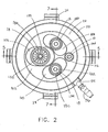
- FIG. 2 is top view of the surgical access device of FIG. 1 ;
- FIG. 3 is an exploded view of the surgical access device of FIG. 1 ;
- FIG. 4 is an exploded view of a base member included in the surgical access device of FIG. 1 ;
- FIG. 5 is a cross-sectional view of the surgical access device of FIG. 1 ;
- FIG. 6 is a cross-sectional view of a sealing member of the surgical access device of FIG. 1 ;
- FIG. 7 is another cross-sectional view of the surgical access device of FIG. 1 ;
- FIG. 8 is another cross-section view of the sealing membrane of the surgical access device of FIG. 1
- FIG. 9 is a perspective view of the surgical access device of FIG. 1 with a surgical instrument disposed through a sealing element and positioned at an angle with respect to a central longitudinal axis of the surgical access device;
- FIG. 10 is a cross-section view of the surgical access device of FIG. 1 showing a surgical instrument disposed through a sealing element and positioned at an angle with respect to the central longitudinal axis of the surgical access device;
- FIG. 11 is a perspective view of the surgical access device of FIG. 1 disposed in tissue and having three surgical instruments disposed through three sealing elements;
- FIG. 12 is a perspective view of the surgical access device of FIG. 1 disposed in tissue and having three surgical instruments disposed through three sealing elements at various angles;
- FIG. 13 is a cross-sectional view of the surgical access device of FIG. 1 showing surgical instruments disposed through the sealing elements;
- FIG. 14 is a perspective view illustrating a first range of motion of the surgical access device of FIG. 1 ;
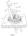
- FIG. 15 is a perspective view illustrating a second range of motion of the surgical access device of FIG. 1 ;
- FIG. 16 is a perspective view illustrating a third range of motion of the surgical access device of FIG. 1 ;
- FIG. 17 is a perspective view illustrating all three ranges of motion of FIGS. 17-19 ;
- FIG. 18 is a perspective view of the surgical access device of FIG. 1 disposed in tissue with a surgical instrument disposed within a sealing element;
- FIG. 19 is a perspective view of a housing support and a retractor of the surgical access device of FIG. 1 disposed in tissue with a top portion of the housing detached therefrom;
- FIG. 20 is a cross-sectional view of tissue being removed through the retractor and the housing support of the surgical access device of FIG. 1 ;
- FIG. 21 is a cross-sectional view of the surgical access device of FIG. 1 including one embodiment of a safety shield;
- FIG. 22 is a perspective view of the safety shield of FIG. 21 ;
- FIG. 23 is an exploded view of the safety shield of FIG. 21 ;
- FIG. 24 is a cross-sectional side view of a second embodiment of a safety shield
- FIG. 25 is a cross-sectional top view of the safety shield of FIG. 24 ;
- FIG. 26 is a cross-sectional side view of a third embodiment of a safety shield
- FIG. 27 is a cross-sectional top view of the safety shield of FIG. 26 ;
- FIG. 28 is a perspective view of the safety shield of FIG. 26 ;
- FIG. 29A is a cross-sectional view of another embodiment of a base member of a surgical access device having rotatable sealing elements
- FIG. 29B is an exploded view of the base member of FIG. 29A illustrating rotatable rims for rotating the sealing elements;
- FIG. 30 is one embodiment of locking mechanism for preventing rotation of the rotatable rims of FIG. 29B ;
- FIG. 31A is a perspective view of one embodiment of a base member with multiple rotatable rings
- FIG. 31B is a top view of the base member of FIG. 31A showing movable flexible arms
- FIG. 31C is a cross-sectional view of the base member of FIG. 31A ;
- FIG. 31D is a top view of the base member of FIG. 31A ;
- FIGS. 31E is a perspective view of an adjustment mechanism of the base member of FIG. 31A .
- FIG. 32A is a cross-sectional view of a base member of a surgical access device having a flush sealing element
- FIG. 32B is a cross-sectional view of a base member of a surgical access device having a recessed sealing element
- FIG. 33A is a perspective view of a base member having a flexible bellows sealing member
- FIG. 33B is a top view of the base member of FIG. 33A ;
- FIG. 34A is an exploded view of three rotatable base members having sealing elements therein;
- FIG. 34B is a cross-sectional view of the base members of FIG. 34A positioned in a housing;
- FIG. 35A is a cross-sectional view of an exemplary base member having multiple layers of sealing elements
- FIG. 35B is a perspective view of the base member of FIG. 35A ;
- FIG. 36A is an exploded view of a base member having a flexible sealing membrane and a plurality of rotatable rims;
- FIG. 36B is a perspective view of the base member of FIG. 36A ;
- FIG. 37A is a cross-sectional view of a gimbal seal
- FIG. 37B is a perspective of the gimbal seal of FIG. 37A having an instrument positioned therein;
- FIG. 37C is a perspective of the gimbal seal of FIG. 37A ;
- FIG. 37D is another perspective view of the gimbal seal of FIG. 37A .
- FIG. 38A is a top view of one embodiment of a base member having tracks formed therein;
- FIG. 38B is a perspective view of the base member of FIG. 38A ;
- FIG. 38C is a cross-sectional view of a sealing element in the base member of FIG. 38A ;
- FIG. 39A is a top view of another embodiment of a base member having rotatable rims.
- FIG. 39B is a cross-sectional view of the base member of FIG. 39A .
- the present invention generally provides improved surgical access devices that allow multiple surgical instruments to be inserted into sealing elements of a single surgical access device.
- the improved surgical access devices allow surgical instruments inserted through the sealing elements to be moved laterally, rotationally, angularly, and vertically for ease of manipulation within a patient's body while maintaining insufflation.
- a housing having a base member with a plurality of sealing elements coupled thereto for receiving and forming a seal around surgical instruments inserted therein.
- the base member can provide one or more predetermined paths, predefined movement regions, and/or predefined elongate pathways that can guide lateral, independent movement of the sealing elements therein, thereby allowing for lateral movement of surgical instruments inserted within the sealing elements.
- the housing can define a central longitudinal axis, and the plurality of sealing elements can each have a central axis that can be angularly adjustable relative to the central longitudinal axis of the housing within the predetermined paths of the base member, thereby allowing a surgeon more control over the insertion of multiple surgical instruments.
- the plurality of sealing elements can be collectively rotated about the central axis of the housing to enable greater surgeon maneuverability within the device.
- the various surgical access devices can further include a wound protector, cannula, ring retractor, or other member for forming a pathway through tissue (hereinafter generally referred to as a retractor).
- the retractor can extend from the housing and it can be configured to be positioned within an opening in a patient's body.
- the sealing elements can each define working channels extending through the housing that are generally aligned with the retractor.
- Any and all of the surgical access devices described herein can also include various other features, such as one or more ventilation ports to allow evacuation of smoke during procedures that utilize cautery and/or one or more insufflation ports through which the surgeon can insufflate the abdomen to cause pneumoperitenium, as described for example in U.S. Patent Application No.
- the insufflation port can be any size and can accept a leur lock or a needle, as will be appreciated by those skilled in the art.
- the surgical access devices disclosed herein can be utilized to provide access to a patient's body cavity.
- the retractor can be positionable within an opening in a patient's body such that a distal portion of the retractor extends into a patient's body cavity and a proximal portion is coupled to a housing positioned adjacent to the patient's skin on an exterior of the patient's body.
- a lumen in the retractor can form a pathway through the opening in a patient's body so that surgical instruments can be inserted from outside the body, through the sealing elements, to an interior body cavity.
- the elasticity of the skin of the patient can assist in the retention of the retractor in the body opening or incision made in the body.
- the retractor can be placed in any opening within a patient's body, whether a natural orifice or an opening made by an incision.
- the retractor can be substantially flexible so that it can easily be maneuvered into and within tissue as needed.
- the retractor can be rigid or semi-rigid.
- the retractor can be formed of any suitable material known in the art, for example silicone, urethane, thermoplastic elastomer, and rubber.
- most surgical access devices typically include at least one seal disposed therein to prevent air and/or gas from escaping when surgical instruments are inserted therethrough.
- Some of the embodiments disclosed herein can be used with only one type of seal, for example an instrument seal, that prevents air and/or gas from escaping when a surgical instrument is inserted therethrough, but otherwise does not form a seal when no instrument is disposed therethrough.
- inventions can include various sealing elements that are known in the art, and can include at least one instrument seal, at least one channel seal or zero-closure seal that seals the working channel created by the sealing port when no instrument is disposed therethrough, and/or a combination instrument seal and channel seal that is effective to both form a seal around an instrument disposed therethrough and to form a seal in the working channel when no instrument is disposed therethrough.
- various seals known in the art can be used including, for example, duckbill seals, cone seals, flapper valves, gel seals, diaphragm seals, lip seals, gimbal seals, deep cone seals, iris seals, slit seals, etc.
- any combination of seals can be included in any of the embodiments described herein, whether or not a particular seal combination is specifically discussed in the corresponding description of a particular embodiment.
- exemplary surgical access devices provide for greater maneuverability of surgical instruments within a patient while maintaining insufflation.
- this greater maneuverability can be provided by having predefined movement regions, predefined elongate pathways, tracks, and/or predetermined paths formed within the housing that allow sealing elements, and surgical instruments disposed within the sealing elements, to be independently moved within and/or along the predetermined paths to allow for a greater range of motion.
- the sealing elements can be angled relative to the predetermined paths to allow for angular manipulation of the surgical instruments as well as lateral movement along the predefined paths.
- each sealing element can include a flexible sealing membrane that can be integrally formed with a flexible sealing member.
- the flexible sealing member can provide a gas tight seal within the housing and across the working channel and can stretch, twist, bunch, and otherwise deform to allow the sealing elements to move laterally, angularly, and vertically within their predetermined paths and relative to other sealing elements.
- the entire sealing member can be rotated 360 degrees to thereby rotate the sealing elements to allow a change in position of surgical instruments inserted through the sealing elements.
- the surgical access device 10 can generally include a housing 12 with a retractor 28 extending distally therefrom.
- the housing 12 and the retractor 28 can define a working channel extending therethrough and a central longitudinal axis 30.
- the housing 12 can generally include one or more sealing elements 18 and/or sealing members 48 and the retractor 28 can be configured to be positioned within an opening in a patient's body to provide access to an interior surgical site.
- the tissue surrounding an opening in which the retractor 28 is placed can exert a pressure on the retractor 28 to hold the retractor 28 in place within a body such that the housing 12 is positioned against tissue on the exterior of the body. In this way, an access pathway to an interior surgical site is created through which surgical instruments can be inserted to perform a surgical procedure.
- the retractor 28 can extend from the housing, and in one embodiment, the retractor 28 is a substantially flexible member having a proximal flange 32 and a distal flange 34 with an inner elongate portion 36 extending therebetween.
- the proximal flange 32 can be positioned within a distal portion of the housing 12.
- a proximal o-ring 38 can be included within the proximal flange 32 to add structural support to the proximal flange 32 and to aid in allowing rotation of the housing 12 relative to the retractor 28, as will be described in more detail below.
- a distal o-ring 40 can optionally be included within the distal flange 34 of the retractor 28 to provide structural support to the retractor 28 within a patient's body.
- the proximal and distal o-rings 38, 40 can be flexible or substantially rigid as needed for use in a particular application.
- the device 10 can include a housing cover 14 and a housing support 42 that can be mated together to generally form the structure of the housing 12.
- the housing 12 can further include a base member 16 and a base member support 44 secured between the housing cover 14 and the housing support 42.
- the housing cover 14 can be formed of a crown 20 and cover flange 22 with one or more latches 24 extending from the cover flange 22 to aid in securing the housing cover 14 to the housing support 42.
- the crown 20 of the housing cover 14 can generally serve as a top most portion of the housing 12 and is in the shape or form of a ring defining an opening 46 in the housing cover 14 that allows access to the sealing elements 18.
- the crown 20 can have a diameter that is, for example, smaller than a diameter of the cover flange 22. In other embodiments, the crown 20 can have a diameter that is the same as, or larger than, a diameter of the cover flange 22 depending on the requirements of a particular surgical access device.
- the crown 20 and the cover flange 22 are integrally formed as a single component and the cover flange 22 extends distally at an angle from the crown 20 in an expanding diameter.
- the crown 20 and the cover flange 22 can be adhered and/or fastened together with any mating mechanism known in the art, such as adhesive, screws, threads, etc.
- the cover flange 22 can have a ring-like shape with a diameter that can generally define an outer diameter or outer circumference of the housing 12.
- a distal surface 50 of the cover flange 22 can be substantially level or flat to enable flush mating with an outer rim 52 of the base member support 44.
- a notch 26 can be formed in the cover flange 22 to receive an insufflation access port 54 formed in the base member support 44 that can receive an insufflation port 56.
- One or more apertures or openings 58 shown in FIGS. 5 and 6 , can be formed into the cover flange 22 around a circumference thereof to enable further mating between the housing cover 14 and the base member support 54, as will be described in more detail below.
- the openings 58 in the cover flange 22 can extend upward or proximally from the distal surface 50 of the cover flange 22 to a lower or distal surface 60 of the crown 20.
- any number of mating or coupling mechanisms can be formed in and/or around the housing cover 14 to allow mating with other components of the housing 12.
- one or more latches 24 can extend from the cover flange 22 of the housing cover 14 to allow the housing cover 14 to mate or couple with the housing support 42.
- the latches 24 can include a recessed groove 62 having an inner lip 64 that can support and seat an outer rim 66 formed by a recessed portion 68 of the housing support 42.
- the recessed groove 62 within the latch 24 can also receive a recessed lip 70 of the base member support 44 seated on top of the outer rim 66, thereby securing all components of the housing 12 together.
- An outer lip 72 of the latch 24 allows for the latch 24 to be manually moved outward and upward, as indicated by the directional arrow A in FIG.
- any number of mating and/or coupling mechanisms can be used to mate the housing cover 14 with the rest of the housing 12, including but not limited to, adhesives, threads, screws, bayonet latches, etc.
- the housing support 42 is illustrated as a generally ringshaped member having a seating flange 74 with a circumferential sidewall 76 extending proximally from an outer circumference of the seating flange 74.
- the seating flange 74 can be configured to seat the proximal flange 32 of the retractor 28 such that a top surface 78 of the proximal flange 32 is positioned slightly below a top surface 80 of the circumferential sidewall 76.
- the proximal flange 32 can generally be seated within the housing support 42 without the aid of any securement mechanism in order to allow the housing 12 to be moved relative to the retractor 28.
- the proximal flange 32 of the retractor 28 can have a diameter smaller than a diameter of the circumferential sidewall 76, and in some embodiments, can have a diameter significantly smaller than a diameter of the circumferential sidewall 76 to allow for both lateral, sliding movement and rotational, sliding movement of the housing 12 relative to the retractor 28. In other embodiments, the diameter of the proximal flange 32 can be only slightly smaller than a diameter of the circumferential sidewall 76 to prevent such lateral, sliding movement while still allowing for rotational, sliding movement.
- the housing support 42 can optionally include one or more frictional protrusions 82 extending inward from an inner surface 84 of the circumferential sidewall 76 to provide a surface against which the proximal flange 32 can move as the housing 12 is being moved or rotated relative to the retractor 28.
- the inner elongate portion 36 of the retractor 28 can extend proximally through the opening formed in the housing support 42, thereby defining the working channel through which instruments can be inserted.
- the housing support 42 can have many configurations, in the illustrated embodiment, the top surface 80 of the circumferential sidewall 76 has a diameter equal to a diameter of the base member support 44 and can thus sit flush against a bottom or distal surface 86 of the base member support 44.
- the sidewall 76 can also have other diameters smaller or larger than the base member support 44 as needed in a particular application.
- the housing support 42 can have one or more recessed portions 68 formed in the circumferential sidewall 76 for mating with one or more latches 24 of the housing cover 14.
- the proximal outer rim 66 of the recessed portion 68 can be seated by the inner lip 64 of the recessed grooves 62 of the latches 24 extending from the housing cover 14.
- the base member 16 and the base member support 44 can be secured between the housing cover 14 and the housing support 42.
- the base member 16 can generally be seated or disposed within the base member support 44, and the base member support 44 can provide the connection or coupling to the housing cover 14 and the housing support 42.
- the base member support 44 has a planar flange portion in the shape of a ring with a circular sidewall 88 extending proximally from the planar flange portion such that the flange portion is divided into two sections.
- a first section or inner rim 90 forms a seating area with the sidewall 88 for receiving and seating the base member 16.
- the second section or outer rim 52 provides mating elements for mating the base member support 42 to the housing cover 14.
- an inner surface 94 of the sidewall 88 can include threads formed therearound and/or another engagement mechanism for mating with corresponding threads or engagement mechanisms formed on an outer circumference 92 of the base member 16, thereby securing the base member while still allowing rotation thereof.
- the base member 16 fits securely within the base member support 44 through a loose press fit and/or interference fit connection between the outer circumference 92 of the base member 16 and the inner surface 94 of the sidewall 88.
- the loose press fit or interference fit can be such that the base member 16 is freely rotatable in both directions relative to the base member support 42 and the rest of the housing 12. Rotation of the base member 16 relative to the base member support 42 and the housing 12 allows rotation of all of the sealing elements 18 disposed within the base member 16 as a unit, as will be described further below.
- the outer rim 52 of the base member support 42 can include one or more mating protrusions 96 extending therefrom for mating with one or more corresponding openings 58 in the housing cover 14.
- a press fit, interference fit, and/or adhesive can be used to join the protrusions 96 with the openings 58 in the housing cover 14.
- a proximal or top surface of the outer rim 52 can be positioned adjacent to the distal surface 50 of the cover flange 22.
- the outer rim 52 can have an outer circumference that is substantially flush with the outer circumference of the cover flange 22.
- the distal or bottom surface 86 of the outer rim 52 can be positioned adjacent to the top surface 80 of the circumferential wall 76 of the housing support 42, and its outer circumference can also be substantially flush with the outer circumference of the housing support 42.
- One or more recessed slots 70 can be formed around an outer circumference of the outer rim 52 to correspond with the recessed portions 68 formed in the housing support 42 for receiving the housing cover latch 24. As noted above, the recessed portion 68 can be securely grasped on top of the outer rim 66 of the housing support 42 within the groove 62 of the latch 24.
- the insufflation access port 54 can be formed in the base member support 44 and can consist of an opening 100 extending from the outer circumference of the outer rim 52 and through the sidewall 88 into the working channel.
- the opening 100 can receive the insufflation port 56 for introducing insufflation gases through the working channel and into a body.
- the opening 100 can extend into the working channel at a position below or distal to the base member 16 and the sealing elements 18 disposed in the base member 16. In this way, insufflation gases can be introduced and retained in the working channel and body by the sealing elements 18 when surgical instruments are inserted therethrough.
- the insufflation port 56 extends perpendicularly to the central longitudinal axis 30 of the housing 12, but as will be appreciated by those skilled in the art, insufflation access ports 54 can be positioned at any suitable place within the housing 12. In addition, the insufflation ports 56 can extend from the housing 12 at any angle relative to its central longitudinal axis 30, including parallel thereto.
- the base member 16 can include an upper bearing plate 102, a lower bearing plate 104, and the sealing member 48 disposed between the two bearing plates 102, 104.
- the sealing elements 18 can extend through the sealing member 48 and the bearing plates 102, 104, as will be described in more detail below.
- the upper and lower bearing plates 102, 104 can each include one or more predefined movement regions, predefined elongate pathways, predetermined paths, and/or tracks formed therein that are provided to guide movement of the sealing elements 18.
- the bearing plates 102, 104 are generally each substantially flat, circular elements that, in some embodiments, can be substantially rigid.
- bearing plates 102, 104 can be substantially flexible as needed in a particular application.
- Each bearing plate 102, 104 can be formed of any suitable material known in the art, including but not limited to, polycarbinate and/or high density polyethelene.
- three generally elongate tracks 106, 108, 110 are provided in the upper and lower bearing plates 102, 104 for receiving three movable sealing elements 18a, 18b, 18c therein.
- a fourth, generally circular opening 112 is provided to receive a more constrained, non-movable sealing element 18d therein.
- any number of tracks can be disposed in the bearing plates 102, 104 as needed.
- the tracks 106, 108, 110 can have any size, shape, length, and curvature known in the art, in the illustrated embodiment, the tracks 106, 108, 110 are generally elongate and have a width substantially corresponding to a diameter of the sealing element 18 disposed therein and a length corresponding to between about one and a half to two times the diameter of the sealing element 18 disposed therein. In other embodiments, the tracks 106, 108, 110 can have a width and/or a length corresponding to anywhere between about two to five times a diameter of the sealing element 18 disposed therein.
- the number of tracks within a bearing plate can range between one and any number (two, three, four, five, six, etc.) that can reasonably fit within a diameter of the bearing plates 102, 104.
- a single track formed within the base member 16 can have a substantially large size relative to the size of the bearing plates 102, 104, while multiple tracks formed within the base member 16 can have a smaller size relative to the size of the bearing plates 102, 104.
- Multiple tracks can also have substantially different sizes from one another.
- the tracks 106, 108, 110 can generally be positioned and spaced within the upper and lower bearing plates 102, 104 in any way as needed in a particular application.
- a first track 106 is a substantially straight track and extends from a position adjacent to an outer diameter of the upper and lower bearing plates 102, 104 into a center portion of the plates 102, 104.
- Second and third tracks 108, 110 can be positioned on opposite sides of the first track 106 and can also extend from a position adjacent to an outer diameter of the upper and lower bearing plates 102, 104. As shown, the second and third tracks 108, 110 curve slightly inward around a portion of the first track 106 that extends into the center of the bearing plates 102, 104.
- the fourth opening 112 is disposed at a position substantially opposite to a position of the first track 106.
- the tracks 106, 108, 110 can be situated around a diameter of the bearing plates 102, 104 or, as shown in FIGS. 38A-38C , tracks 106', 108', 110' can all extend from an outer diameter into a center of the bearing plates 102', 104'.
- the bearing plates 102', 104' can have a sealing element 18' formed therein with a flexible sealing member 48' therearound.
- all of the tracks 106, 108, 110 can be straight and in other embodiments, all of the tracks 106, 108, 110 can have a curvature.
- the upper bearing plate tracks 106a, 108a, 110a can have smooth interior sidewalls 116 to enable smooth movement of the movable sealing elements 18a, 18b, 18c within the upper bearing plate tracks 106a, 108a, 110a.
- the lower bearing plate tracks 106b, 108b, 110b can have interior sidewalls with a smooth proximal portion 114 corresponding in size to the sidewalls 116 of the upper bearing plate tracks 106a, 108a, 110a to enable smooth movement of the sealing elements 18a, 18b, 18c within the tracks 106b, 108b, 110b.
- a lower or distal portion 118 of the sidewalls can extend or protrude slightly into the tracks 106b, 108b, 110b to form a lip extending therearound that has a size slightly smaller than a size of the proximal portion 114 and a size of the sidewalls 116 of the upper bearing plate tracks 106a, 108a, 110a.
- the sealing elements 18a, 18b, 18c can move and/or slide along the lip formed in the lower bearing plates tracks 106b, 108b, 110b and vertical and/or longitudinal movement of the sealing elements 18a, 18b, 18c below the lower bearing plate tracks 106b, 108b, 110b is restrained or prohibited while vertical and/or longitudinal movement of the sealing elements 18a, 18b, 18c above the upper bearing plate tracks 106a, 108a, 1 10a is not restrained or prohibited.
- the sidewalls 116, 114, 118 of the upper and lower bearing plate tracks 106a, 106b, 108a, 108b, 110a, 110b are completely smooth, with no lip, such that vertical and/or longitudinal movement below and above the tracks is allowed.
- engagement elements such as grooves or recesses, can extend around the sidewalls 116, 114, 118 in the upper and/or lower bearing plate tracks 106a, 106b, 108a, 108b, 110a, 110b that are configured to mate with corresponding engagement elements formed around the sealing elements 18a, 18b, 18c to provide constrained vertical and/or longitudinal movement of the sealing elements 18a, 18b, 18c while allowing lateral, guided movement within the tracks 106, 108, 110.
- a person skilled in the art will appreciate the various ways of allowing or preventing movement of the sealing elements 18a, 18b, 18c within the bearing plate tracks 106, 108, 110 as needed for a particular application.
- one or more tracks 106, 108, 110 can provide constrained movement of a sealing element 18a, 18b, 18c disposed therein while one or more tracks 106, 108, 110 can provide a full range of movement and/or motion of a sealing element 18a, 18b, 18c disposed therein.
- the upper and lower bearing plates 102, 104 can be joined or coupled together by any method known in the art, including but not limited to, adhesive, screws, press fit, interference fit, etc.
- one or more cylindrical protrusions 120 and one or more elongate protrusions 122 are formed around an outer rim 124 of the lower bearing plate 104 such that they extend proximally therefrom.
- the cylindrical protrusions 120 are configured to extend through securement openings 126 formed around an outer diameter of the sealing member 48 and into corresponding openings 128 formed around an outer diameter of the upper bearing plate 102 such that a press fit or interference fit is achieved between the cylindrical protrusions 120 and the openings 128 in the upper bearing plate 102.
- the elongate protrusions 122 are configured to secure the lower bearing plate 104 to the sealing member 48 and thus extend into corresponding elongate slots 130 formed around the outer diameter of the sealing member 48. In this way, the base member 16 is secured together with the sealing member 48 coupled between the upper and lower bearing plates 102, 104.
- the sealing member 48 can have many configurations and in the illustrated embodiment, the sealing member 48 generally seals the working channel of the surgical access device 10 by providing an air and gas tight seal between the upper bearing plate 102 and the lower bearing plate 104.
- the sealing member 48 can be composed of a flexible, stretchable, and/or deformable material that is able to flex, stretch, bunch and/or otherwise deform to allow the sealing elements 18a, 18b, 18c disposed therethrough to be moved within their respective tracks 106, 108, 110 within the bearing plates 102, 104.
- the sealing member 48 is a relatively thin, deformable membrane that has a diameter corresponding to a diameter of the upper and lower bearing plates 102, 104 such that it can be positioned and form a seal between the upper and lower bearing plates 102, 104.
- the sealing member 48 can be formed of any suitable material known in the art, including but not limited to, silicone, urethane, sanaprene, isoprene, and/or krayton.
- the sealing member 48 can include one or more openings 132 formed therethrough that define openings for one or more sealing elements 18.
- each sealing element 18 can be a movable sealing element, for example, movable sealing elements 18a, 18b, 18c, or a non-movable sealing element, for example, non-movable sealing element 18d.
- Movable sealing elements 18a, 18b, 18c are generally configured to be independently movable within their respective bearing plate tracks 106, 108, 110 relative to the housing, each other, and to non-movable sealing elements.
- the non-movable sealing element 18d is generally configured to be secured within a circular opening, for example, opening 112, in the bearing plates 102, 104 that does not provide room for the sealing element 18d to move.
- the movable sealing elements 18a, 18b, 18c compose a majority of the total number of sealing elements 18 disposed within the base member 16.
- one or more sealing elements 18 can have an opening with a different diameter than an opening of the other sealing elements 18.
- one or more movable sealing elements 18a, 18b, 18c can have an opening with a diameter that is the same as, larger than, or smaller than openings in other movable sealing elements 18a, 18b, 18c and in other non-movable sealing element 18d.
- One or more non-movable sealing elements 18d can have an opening with a diameter that is the same as, larger than, or smaller than openings in other non-movable sealing elements (not shown) and in other movable sealing elements 18a, 18b, 18c.
- the sealing elements 18 can have many configurations and constructions, but in the illustrated embodiment, the sealing elements 18 each include a sealing membrane 134, formed integrally with the sealing member 48, that is configured to form a seal around a surgical instrument positioned therethrough.
- the sealing membrane 134 can generally have a cone-like shape with flexible conical walls 136 and an opening 138, shown most clearly in FIGS. 5 and 6 , at the apex of the cone that is smaller than a diameter of a surgical instrument such that the opening 138 can deform to form a seal around an instrument inserted therethrough.
- Each sealing membrane 134 can be the same as every other sealing membrane 134 or one or more sealing membranes 134 can be different than another. As shown in FIGS.
- the sealing membrane 134 of sealing element 18a can have a fluted form in which the conical walls 136 are folded in v-shaped, accordion style folds. This construction assists in preventing eversion of the sealing membrane 134 when an instrument is withdrawn from the sealing element 18a.
- the fluted form bunches beneath the sealing member 48 and thus provides a bracing that prevents the sealing element 18a from everting.
- the conical walls 136 of the sealing elements 18b, 18c do not have fluted forms and instead have a steep angle ⁇ relative to a lateral plane of the sealing member 48, as shown in FIG.
- any of the sealing elements 18 can have one or more of the various available constructions for their respective sealing membrane 134.
- the sealing elements 18 can also be formed as separate elements apart from the sealing member 48 and do not have to be formed integrally therewith.
- the sealing elements 18 can be constructed in various ways, but in the illustrated embodiment, the sealing elements 18 can include upper and lower seal supports 140, 142, shown most clearly in FIG. 4 .
- the upper and lower seal supports 140, 142 can be substantially rigid rings that are configured to engage upper and lower surfaces of a perimeter of the opening 132 of the sealing member 48 therebetween.
- the seal supports 140, 142 serve to further define the openings formed through the sealing member 48, provide support thereto for the insertion and withdrawal of surgical instruments, and for the movable sealing elements 18a, 18b, 18c, can provide a structure that can move, slide, and/or otherwise travel along and within the tracks 106, 108, 110 in the upper and lower bearing plates 102, 104.
- the upper and lower seal supports 140, 142 can be joined or coupled together by any method known in the art including, but not limited to, adhesives, screws, threads, etc.
- the lower seal support 142 includes several cylindrical protrusions 144 and several elongate protrusions 146 formed around its circumference and extending in a proximal direction from its proximal surface 148.
- the cylindrical protrusions 144 can extend through corresponding openings 149 formed around a circumference of the sealing element openings 132 in the sealing member 48 and into corresponding openings 152 within the upper seal supports 140.
- the elongate protrusions 146 can extend through corresponding elongate slots 150 formed adjacent to the circumference of the sealing element openings 132 formed in the sealing member 48.
- each sealing membrane 134 is clamped, coupled, or otherwise secured between the upper and lower seal supports 140, 142.
- the sealing elements 18 are able to form an air and gas tight seal around a surgical instrument inserted therethrough while the sealing member 48 seals the rest of the working channel between the upper bearing plate 102 and the interior of a body.
- the sealing member 48 is flexible and thus will stretch, bunch, twist and otherwise deform in response to movement of the various sealing elements 18a, 18b, 18c within the upper and lower bearing plate tracks 106, 108, 110. More particularly, because the upper and lower seal supports 140, 142 grasp the sealing member 48 around the sealing membranes 134, the sealing elements 18a, 18b, 18c are able to pull and push the sealing member 48 in response to movement of surgical instruments disposed therein.
- the sealing elements 18a, 18b, 18c are each independently movable laterally within and along the length and/or width of their respective bearing plate tracks 106, 108, 110.
- Each of the sealing elements 18a, 18b, 18c can independently and selectively be moved laterally from an initial resting position, such as a relatively center position in the tracks 106, 108, 110 to either of opposed ends of the tracks 106, 108, 110, and anywhere in between, whether along a straight line of a track 106 or along a curved path that follows the curve of tracks 108, 110.
- an initial resting position such as a relatively center position in the tracks 106, 108, 110 to either of opposed ends of the tracks 106, 108, 110, and anywhere in between, whether along a straight line of a track 106 or along a curved path that follows the curve of tracks 108, 110.
- the seal member 48 In the initial position, the seal member 48 is not stretched, and in the moved position, the seal member 48 stretches to allow a seal to be
- the tracks 106, 108, 110 containing each sealing element 18a, 18b, 18c define the predetermined path of movement allowed.
- a surgical instrument 900 is inserted through the sealing element 18a, which is moved from its natural, center position within the track 106 to one end of the track 106 near the outer circumference of the device 10.
- a surgical instrument 902 is positioned within sealing element 18b, which is also moved from its natural, center position in the track 108 to one end of the track 108.
- a surgical instrument 904 is positioned within the sealing element 18c and is positioned in a center portion of the track 110 in FIG. 11 and is moved to one end of the track 110 in FIG. 12 . Accordingly, some variations of the possible lateral movement of the sealing elements 18a, 18b, 18c within their respective tracks 106, 108, 110 can be seen. Of course, many other variations and combinations of lateral movement are also possible.
- Each sealing element 18a, 18b, 18c can also be moved angularly within each track 106, 108, 110 such that a longitudinal axis of the sealing element 18a, 18b, 18c is movable and adjustable relative to the central longitudinal axis 30 of the housing 12.
- the sealing elements 18a, 18b, 18c can be pivoted out of a lateral plane of the tracks 106, 108, 110 within the base member 16.
- the sealing member 48 can stretch and bunch around each sealing element 18a, 18b, 18c to enable each sealing element 18a, 18b, 18c to be pivoted to an angle with respect to the lateral plane while maintaining a seal around an instrument inserted therethrough.
- the sealing elements 18a, 18b, 18c are angularly adjustable at any position along a lateral, long-axis of the elongate tracks 106, 108, 110.
- a central longitudinal axis 930 of the sealing element 18a, in which the surgical instrument 900 is disposed is positioned at an angle ⁇ with respect to the central longitudinal axis 30 of the housing 12.
- the sealing element 18b, in which the surgical instrument 902 is disposed is moved from a position in which its central longitudinal axis 932 is parallel with the central longitudinal axis 30 of the housing 12 ( FIG.
- the sealing elements 18a, 18b, 18c can be angularly adjustable at any position along both a long-axis and a short-axis of the elongate tracks 106, 108, 110, and/or angularly adjustable at any position around 360 degrees laterally within the tracks 106, 108, 110.
- the sealing elements 18a, 18b, 18c can also be moved vertically relative to the base member 16 and parallel relative to the central longitudinal axis 30 of the housing 12.
- the lips formed in the lower bearing plate tracks 106b, 108b, 110b can prevent vertical movement below the bearing plate tracks 106b, 108b, 1110b, while vertical movement above the upper bearing plate tracks 106a, 108a, 110a is allowed.
- a surgical instrument disposed within a sealing element 18a, 18b, 18c can be pulled proximally from the sealing element 18a, 18b, 18c, whether for complete withdrawal or for adjustment purposes, and the movement can lift the sealing elements 18a, 18b, 18c above the plane of the base member 16.
- vertical movement is allowed in both directions above and below the bearing plate tracks 106, 108, 110.
- a particular sealing element 18a, 18b, 18c can be independently moved laterally within a track 106, 108, 110 while its central longitudinal axis is at an angle relative to the central longitudinal axis 30 of the housing 12.
- a particular sealing element 18a, 18b, 18c can be independently moved vertically while its central longitudinal axis is at an angle relative to the central longitudinal axis 30 of the housing 12. Such vertical movement is thus no longer strictly parallel to the central longitudinal axis 30 of the housing 12, but is instead movement that is at an angle relative to the central longitudinal axis 30 of the housing 12.
- each movable sealing element 18a, 18b, 18c is accomplished due to the flexibility of the sealing member 48 being configured to stretch, twist, bunch, and otherwise deform in response to the movement.
- all such movement is performed while the working channel is sealed due to the seal formed by the sealing elements 18a, 18b, 18c around a surgical instrument inserted therethrough and due to the flexibility of sealing member 48 that able to maintain a seal during deformation.
- the base member 16 can also be rotated within and relative to the base member support 44, and thus relative to the housing 12. Accordingly, the base member 16 provides multiple ways in which the sealing elements 18 can be moved to provide better access for surgical instruments inserted therein.
- the sealing elements 18 can all be rotated as a collective unit around the central longitudinal axis 30 of the housing 12.
- each sealing element 18a, 18b, 18c can be moved laterally, angularly, and vertically within the base member 16, as described above, to enable better access and maneuverability.
- FIGS. 14-17 illustrate one embodiment of the range of motion that the surgical access device 10 can provide during surgical procedures.
- FIGS. 14-16 illustrate a series of possible ranges of motion for various positions of the sealing elements 18.
- FIG. 17 combines the three series shown in FIGS. 14-16 to give a complete picture of one embodiment of the range of motion possible with the surgical access device 10.
- a first surgical instrument 940 disposed through the sealing element 18c
- a second surgical instrument 942 disposed through the sealing element 18b
- a target diameter 944 is illustrated and represents the target space over which one or both of the first and second surgical instruments 940, 942 can move during a surgical procedure.
- the first surgical instrument 940 is positioned through the sealing element 18c, which is positioned at a left-hand end of the track 110.
- the second surgical instrument 942 is positioned through the sealing element 18b, which is positioned at a left-hand end of the track 108.
- the two sealing elements 18c, 18b are positioned at the same, left-hand end of the tracks 110, 108. In this position, there is a triangular shaped space 946a behind the surgical instrument 940 that cannot be accessed by any angular movement of the second instrument 942.
- a key-hole shape 948a is also shown and generally illustrates the area over which the instrument 942 cannot reach while in this lateral position within the track 108 due to, for example, handle and shaft interference between the two instruments 940, 942.
- the entire target diameter 944, minus the triangle 946a and the key-hole shape 948a can be reached by the second surgical instrument 942 during a surgical procedure while the sealing elements 18c, 18b are in the far, left-hand end position within their tracks 110, 108.
- the target diameter 944 is again illustrated.
- the first surgical instrument 940 is positioned through the sealing element 18c, which is positioned at a center portion of the track 110.
- the second surgical instrument 942 is positioned through the sealing element 18b, which is positioned at a center portion of the track 108. In this position, there is a triangular shaped space 946b behind the first surgical instrument 940 that cannot be accessed by any angular movement of the second surgical instrument 942. As the second surgical instrument 942 is moved through its entire angular range, it will pass over the first surgical instrument 940, as illustrated by the arrow B.
- a key-hole shape 948b is also shown and generally illustrates the area over which the second surgical instrument 942 cannot reach while in this center, lateral position within the track 108 due to, for example, handle and shaft interference between the two instruments 940, 942.
- the entire target diameter 944, minus the triangle 946b and the key-hole shape 948b can be reached by the surgical instrument 942 while the sealing elements 18c, 18b are in center positions within their respective tracks 110, 108.
- the target diameter 944 is again illustrated.
- the first surgical instrument 940 is positioned through the sealing element 18c, which is positioned at a right-hand end of the track 110.
- the second surgical instrument 942 is positioned through the sealing element 18b, which is positioned at a right-hand end of the track 108.
- the two sealing elements 18c, 18b are positioned at the same, right-hand end of the tracks 110, 108. In this position, there is a triangular shaped space 946c behind the first surgical instrument 940 that cannot be accessed by any angular movement of the second surgical instrument 942.
- the second surgical instrument 942 As the second surgical instrument 942 is moved through its entire angular range, it will pass over the first surgical instrument 940, as illustrated by the arrow B.
- a key-hole shape 948c is also shown and generally illustrates the area over which the second surgical instrument 942 cannot reach while in this lateral position within the track 108 due to, for example, handle and shaft interference between the two instruments 940, 942.
- the entire target diameter 944, minus the triangle 946c and the key-hole shape 948c can be reached by the second surgical instrument 942 during a surgical procedure while the sealing elements 18c, 18b are in the far, right-hand end position within their tracks 110, 108.
- FIG. 17 represents the combination of FIGS. 14-16 to illustrate one embodiment of the full range of motion available during a surgical procedure to the second surgical instrument 942 disposed through the surgical access device 10.
- the target diameter 944 is again shown.
- An area 946 enclosed by dotted lines, represents the combination of triangles 946a, 946b, 946c and is essentially an area where a small portion of the target diameter 944 becomes unavailable to the second surgical instrument 942 at each lateral position within the track 108 due to, for example, interference between the two shafts.
- An area 948 is a combination of the key-holes 948a, 948b, 948c and is the only area within the target diameter 944 that can be unavailable to the second surgical instrument 942 during a surgical procedure.
- the target diameter 944 is accessible to the second surgical instrument 942, while another surgical instrument 940 is disposed through the surgical access device 10, just by moving the second surgical instrument 942 along the track 108 and through the various possible angular orientations.
- the inaccessible area 948 is accessible by another surgical instrument disposed through the sealing element 18c and/or 18a.
- the base member 16 is rotatable relative to the rest of the housing 12, and thus with a slight rotation of the base member 16, the second surgical instrument 942 can access the area 948.
- the entire housing 12 is rotatable relative to the retractor 28, providing a similar type of access to the second surgical instrument 942.
- this series of range of motion illustrations is only one example of many possible ranges of motion that the surgical access device 10 can provide.
- the retractor 28 of the exemplary access device 10 can be positioned within any opening in a patient's body, including natural openings and surgically formed openings.
- the retractor is positioned through an opening within tissue 19.
- the retractor 28 is held in place by the tissue 19 within the opening such that the housing 12 is positioned against an outer surface of the patient's body.
- the housing 12 can be rotated in either direction by any amount relative to the retractor 28 to enable proper positioning of the sealing elements 18.
- various surgical instruments for example surgical instrument 27, can be inserted through the movable and immovable sealing elements 18 disposed within the housing 12 and into the working channel of the surgical access device.
- one sealing element 18a has a diameter than is larger than the other sealing elements 18b, 18c, 18d.
- the sealing element 18a can receive the surgical instrument 27 having a larger diameter, such as an endoscopic camera and/or light.
- the immovable sealing element 18d has a diameter smaller than the other sealing elements 18a, 18b, 18c and can receive an instrument with a smaller diameter, for example, a surgical retractor.
- the other two movable sealing elements 18b, 18c can receive any number of other surgical instruments as may be needed in a particular application.
- the sealing elements 18 can have various diameter and that any surgical instrument having a suitable diameter can be inserted in any one of the various sealing elements.
- insufflation of the interior surgical site can be achieved by flowing an insufflation gas through the insufflation port 56 and into the sealed working channel.
- the surgical instruments within the sealing elements 18a, 18b, 18c can then be moved laterally, angularly, and vertically, as described above, to achieve optimal positioning of the surgical instruments within the interior surgical site.
- the base member 16 can be rotated relative to the base member support 44 and the housing 12 to rotate all of the sealing elements 18, and the instruments disposed in the sealing elements 18, as a collective unit.
- the housing 12 can also be rotated as needed to achieve better positioning for, for example, the insufflation port 56.
- the surgical instruments disposed in the sealing elements 18 can be repeatedly and independently moved and manipulated within their respective tracks 106, 108, 110 to facilitate ease of use.
- insufflation pressure can be released through the insufflation port 56, and the surgical instruments can be withdrawn from the sealing elements.
- a top portion 11 of the housing 12, including the housing cover 14, the base member 16, and the base member support 44 can be unlatched and removed from the housing support 42, as shown most clearly in FIG. 20 .
- the retractor 28 remains within the opening in the tissue 19 and the housing support 42 remains adjacent to the tissue 19 on an exterior thereof. Tissue 43 that was cut or dissected during the surgical procedure can be withdrawn through the working channel of the retractor 28 as needed using a surgical instrument 49.
- the retractor 28 can then be removed from the opening in the tissue 19 upon completion of the procedure.
- the top portion 11 of the housing 12 can also be latched back to the housing support 42 as needed if further surgical procedures are required.
- the surgical access device 10 can also include a shield 719 configured to extend through the retractor 28 to thereby provide a protective lining as surgical instruments are inserted through the device 10.
- the shield 719 can have a length corresponding to a length of the retractor 28, but can also have a length less than or considerably longer than the length of the retractor depending on a specific application.
- the shield 719 can be mated to the retractor 28 using any attachment mechanism, e.g., adhesive, screws, press fit, etc., as will be appreciated by a person skilled in the art.
- the shield 719 can be configured to engage a proximal flange 32 of the retractor 28 that is seated in the housing support 42 and the distal surface 86 of the base member support 44.
- the proximal o-ring 38 within the flange 32 can help provide structure to the proximal flange 32 and therefore help provide a more stable engagement surface for the shield 719.
- Lips 720a, 720b can be formed around an outer circumference of a proximal rim 718 of the shield 719 and can fit within and engage a recess 722 formed in the distal surface 86 of the base member support 44 to provide further securement of the shield 719 between the proximal flange 32 and the base member support 44.
- the shield 719 can have any size, shape, and configuration.
- the shield 719 includes a circumferentially expandable, cylindrically-shaped member having an outer layer 719a and an inner layer 719b configured to be disposed within in the outer layer 719a.
- the outer and inner layers 719a, 719b can each respectively include a circumferential proximal rim 721a, 721b having a plurality of flanges 723a, 723b extending radially outward therefrom.
- the outer and inner layers 719a, 719b can include any number of flanges 723a, 723b, and the flanges 723a, 723b can be spaced equidistantly or any other distance apart from one another around their respective proximal rims 721a, 721b.
- the outer and inner flanges 723a, 723b can each be configured to at least partially overlap to form a continuous proximal flange of the shield 719 that is configured to engage the proximal flange 32 of the retractor 28.
- a portion of the outer and inner flanges 723a, 723b can be configured to engage one another to form a "broken" proximal flange of the shield 719.
- none of the outer and inner flanges 723a, 723b can overlap one another when the inner layer 719b is disposed in the outer layer 719a.
- the outer and inner layers 719a, 719b of the shield 719 can also include a plurality of respective distal elongate fingers 725a, 725b distally extending from the proximal rim 721a, 721b and configured to at least partially overlap and engage one another when the inner layer 719b is disposed in the outer layer 719a to form a continuous distal surface configured to engage at least a portion of an inner wall of the inner elongate portion 36 of the retractor 28.
- the distal fingers 725a, 725b can thus be configured to protect the inner elongate portion 36 of the retractor 28 from damage but be configured to be selectively movable when in contact with a surgical instrument such that the surgical instrument can optionally push between the distal fingers 725a, 725b to help provide the surgical instrument with free angular range of motion through the device 10.
- the distal fingers 725a, 725b can also be configured to be selectively movable when the retractor 28 bends when in position in tissue, if the retractor 28 is flexible.
- a shield can include a plurality of layers as discussed above, or a shield can be a singular member, which can make the shield easier to dispose in a retractor.
- FIGS. 24 and 25 illustrate one embodiment of a singular shield 719'.
- the alternate shield 719' can include a circumferential proximal rim 721' with or without radially extending flanges and with a lip 720' for mating with the device 10, as described above.
- the alternate shield 719' can include a pleated distal portion 723' that simulates distal fingers.
- the pleated distal portion 723' can have a variety of sizes, shapes, and configurations.
- the pleated distal portion 723' can include a plurality of box pleats 723a' folded in the shield 719' circumferentially around the distal portion 723'.
- the pleated distal portion 723' can be configured to be selectively movable when the retractor 719' bends, if the retractor 719' is flexible, and/or when a surgical instrument presses against an inner wall of the pleated distal portion 723'.
- a singular retractor shield 719 shown in FIGS.
- the shield 719" can include a pleated distal portion 723" distally extending from a proximal rim 721" having a lip 720" and having a plurality of knife pleats 723 a" formed circumferentially therearound.
- any type of shield can be used as needed in a particular application and can be interchanged before, during, and/or after a procedure as needed.
- a base member 200 of a housing for a surgical access device having three sealing elements 202 attached or coupled to independently slidably rotatable rims 204a, 204b, 204c.
- the three slidably rotatable rims 204a, 204b, 204c are provided concentrically adjacent to one another near an outer circumference of the base member 200.
- the rotatable rims 204a, 204b, 204c can each have an elongate sealing element arm 205 extending radially therefrom.
- the rotatable rims 204a, 204b, 204c can be independently rotatable, thus allowing the sealing element arms 205 extending therefrom to be rotatable relative to the other sealing element arms 205 coupled to the other rims 204a, 204b, 204c.
- a particular sealing element arm 205 can be rotated by a surgical instrument disposed therein, which causes the rim 204a, 204b, 204c to rotate relative to the other rims 204a, 204b, 204c. In this way, independent rotation of the sealing elements 202 relative to each other and relative to the base member 200 can be achieved.
- a flexible sealing member can form at least a center portion of the base member 200, and sealing membranes of each sealing element 202 can be integrally formed with the sealing member.
- the sealing membranes can be, for example, flexible, conically shaped elements that are configured to receive and form a seal around an instrument inserted therethrough.
- the sealing member can stretch, twist, bunch, and otherwise deform to allow movement of the sealing elements 202 around the base member 200 while maintaining a seal across a working channel of the access device.
- the sealing elements 202 can also be moved angularly with respect to a central longitudinal axis of the base member 200, as shown in FIG. 29A , and vertically parallel to the central longitudinal axis of the base member.
- the flexible sealing member can form just a center portion of the base member 200. In other embodiments, the flexible sealing member can form an entire layer of the base member 200.
- FIG. 29B An exemplary mechanism for accomplishing rotation of three independent rims is shown most clearly in FIG. 29B .
- three tracks or grooves 214 can be formed around an outer circumference of the base member 200 and can each receive a slidably rotatable rim 204a, 204b, 204c.
- Each rotatable rim 204a, 204b, 204c can move or slide within its groove 214 to accomplish rotation.
- Each sealing element 202 can be attached to one of the rotatable rims 204a, 204b, 204c and can thereby be rotated around the circumference of the base member 200.
- each rim 204a, 204b, 204c can simply be positioned adjacent to one another such that the rims 204a, 204b, 204c are slidably rotatable relative to each other around the circumference of the base member 200.
- a person skilled in the art will appreciate the various methods of accomplishing rotation of the rims 204a, 204b, 204c.
- each rotatable rim 204 and each groove 214 can be divided into two portions.
- the end of each portion of the rotatable rim 204 can have an opening 218 formed therein for receiving a selectively movable latch 220 that joins the two sections together.
- a bottom portion 222 of the latch 220 is raised to allow the rotatable rim 204 to be moved within its corresponding groove 214 and around the circumference of the base member 200.
- the bottom portion 222 of the latch 220 is lower than the groove 214 and cannot be moved within the groove 214, thereby preventing movement of the rotatable rim 204.
- FIGS. 31A-31E Another exemplary embodiment of a base member 300 for a surgical access device is illustrated in FIGS. 31A-31E .
- the base member 300 is similar to that described above in FIGS. 29A-29B , but includes an additional feature enabling adjustment of a radial length of an elongate member 304 of a sealing element 302 extending into a center of the base member 300.
- One or more slots 312 can be formed in each rotatable rim 310 to receive the elongate member 304 of the sealing element 302.
- An adjustment mechanism in the form of a flexible lever 314 can be inserted through the slots 312 in the rotatable rims 310 to thereby secure a radial length of the elongate member 304.
- the flexible lever 314 can engage sides of the slot 312 to prevent radial adjustment of the elongate member 304.
- a width of the flexible lever 314 can be decreased so that the radial length of the elongate member 304 can be adjusted.
- the elongate member 304 of the sealing element 302 can be made longer by sliding the elongate member 304 inward within the slot 312 to thereby move the sealing element 302 further into a center portion of the base member 300.
- the elongate member 304 of the sealing element 302 can be shortened by sliding the elongate member 304 outward within the slot 312 to thereby pull the sealing element 302 toward the outer circumference of the base member 300 and away from the center portion.
- the sealing elements 302 can each be disposed through and/or formed integrally with a flexible sealing member, similar to those described above, which allows for the radius of each sealing element 302 to be adjusted. As the sealing elements 302 are each moved inward and/or outward relative to the outer circumference of the base member 300, the sealing member can bunches, stretches, twists, and otherwise deforms as needed to allow movement of the sealing element 302 while maintaining an air and gas tight seal across the working channel of the housing. In addition to radial length adjustments, the sealing elements 302 can also be independently rotated via the rotatable rims 310, as described above, and as also facilitated by the flexible sealing member. As with other embodiments, the sealing elements 302 can each be independently moved laterally, angularly, and vertically as needed due to the flexibility of the sealing member 320.
- a flexible retractor 330 is positioned within tissue 332.
- a housing 334 is positioned within the retractor 330 and seats a rotatable base member 336 having a sealing element 338 formed therein.
- the rotatable base member 336 can be generally flush with a top surface of the housing 334 as shown, for example, in FIG. 32A .
- the base member 336 can extend distally at an angle with respect to the top surface of the housing 334 such that the sealing element 338 is in a recessed positioned relative to the top surface of the housing, as shown, for example, in FIG. 32B .
- the base member 336 can also have a semi-flexible or completely flexible sealing membrane to enable the sealing element 338 to be moved between a flush position and a recessed position.
- the base member 400 can include one or more rotatable pathways, for example two pathways 402, 404, extending around the base member 400 at different radii.
- One or more sealing elements for example, sealing elements 406a and 406b, can be disposed within each rotatable pathway 402, 404 and can be rotated 360 degrees around the base member 400 within their respective pathways 402, 404.
- Each pathway 402, 404 contains a flexible membrane, for example a flexible bellows, that can compress and expand in response to movement of the sealing elements 406a, 406b.
- a sealing element 406c can be positioned in a center portion of the base member 400.
- FIGS. 34A and 34B Another exemplary embodiment of a surgical access device 500 is illustrated in FIGS. 34A and 34B .
- the surgical access device includes three base members 502, 504, 506 disposed within a housing 510.
- the three base members 502, 504, 506 are generally positioned vertically within the housing 510, one on top of another, and separated by a distance.
- a sealing element 512 for example a gimbal type seal, is disposed therein and positioned, for example, on one side of each base member 502, 504, 506.
- a flexible sealing member 514 with various openings formed therein and having a substantially crescent or moon-like shape can be positioned on a side of the base members 502, 504, 506 opposite to the sealing element 512.
- the sealing member 514 can be a slit seal having two thin, overlapping silicone or urethane pieces that allow a seal to be maintained between each of the three base members 502, 504, 506 when an instrument is passed therethrough.
- Each base member 502, 504, 506 can be disposed within the housing 510 in such a way that the sealing elements 512 and the sealing members 514 are slightly offset from one another.
- each base member 502, 504, 506 can be rotatable relative to the housing 510 to enable adjustment of their position relative to one another. As shown in FIG.
- the sealing elements 512 and sealing members 514 are offset so that a surgical instrument can be inserted through all three base members 502, 504, 506 and have a range of motion within its respective base member 502, 504, 506 relative to the other base members 502, 504, 506.
- a first surgical instrument 516 can be inserted into the sealing element 512 in the top or proximal most base member 506.
- the first surgical instrument 516 extends through the sealing element 512 and through the openings in the flexible sealing members 514 of the bottom two base members 502, 504.
- the first surgical instrument 516 is sealed within the sealing element 512 in the top base member 506 and can be moved laterally within the sealing members 514 of the bottom two base members 502, 504 to enable greater maneuverability.
- a second surgical instrument 518 can be inserted through the sealing member 514 of the top base member 506, into the sealing element 512 of the middle base member 504, and through the sealing member 514 of the bottom base member 502.
- the second surgical instrument 518 can move laterally within the sealing members 514 of the top and bottom base members 506, 502 and is sealed within the sealing element 512 of the middle base member 504.
- a third surgical instrument 520 can be inserted through the sealing members 514 of the top and middle base members 506, 504 and into the sealing element 512 of the bottom base member 502.
- the third surgical instrument 520 can be laterally movable relative to the top and middle base members 506, 504 and is sealed within the sealing element 512 formed in the bottom base member 502. In this way, each surgical instrument 516, 518, 520 has a greater range of maneuverability within the surgical access device 500.
- FIGS. 35A and 35B Another embodiment is shown in FIGS. 35A and 35B .
- a base member 350 is provided having a plurality of rotatable rings 352 that can be positioned on top of a base member support 354.
- Each ring 352', 352", 352"' can include a movable arm 356 having a sealing element 358 disposed therein.
- the arm 356 can be radially adjustable to move the sealing element 358 between an outer circumference of the base member 350 and a center portion of the base member 350 by any mechanism known in the art.
- a simple press fit or interference fit can exist between the arm 356 and the rings 352', 352", 352"' such that the arm can be held in place using friction and can be manually moved relative to the rings 352', 352", 352"' as needed.
- the sealing elements 358 can be movable angularly relative to the movable arm 356 to allow angular movement of a surgical instrument disposed therethrough.
- a flexible seal member 360', 360", 360"' can form the a center portion of each ring 352', 352", 352"' and can bunch, stretch, and deform to allow the sealing elements 358 to move with the surgical instruments.
- a base member 430 having a plurality of rotatable rings.
- a top rotatable ring 432 can contain a flexible sealing member 434, similar to the flexible membranes described herein.
- the sealing member 434 can include one or more sealing elements 442 disposed therethrough that can be integrally formed with the flexible sealing member 434.
- One or more other rotatable rings 436 for example, three rings 436', 436", 436"' each can have sealing arms 438 extending therefrom and can be stacked one on top of the other beneath the sealing member 434.
- Each ring 436 can be individually rotatable relative to the other rings 436', 436", 436"' and relative to the sealing member 434.
- Each of the sealing arms 438 can include a sealing element 440 positioned at one end thereof and configured to form a seal around an instrument inserted therethrough.
- an instrument can be inserted through the sealing element 442 in the sealing member 434, and into one of the sealing elements 440 in one of the rings 436.
- the instrument can be used to rotate each ring 436 as needed in a procedure, and the sealing member can flex, stretch, and bunch to allow the instrument to move while still maintaining a seal around the instrument.
- FIGS. 39A-39B Another exemplary embodiment of a surgical access device 800 is shown in FIGS. 39A-39B .
- the surgical access device 800 can have a housing 814 with one or more, for example three, triangular-shaped base members 802, 804, 806 stacked one on top of another.
- Each base member 802, 804, 806 can have at least one sealing element 808 and one or more, for example two, slit seals 810 disposed therein.
- surgical instruments can be inserted through the sealing element 808 in one base member 802, 804, 806 and can extend through the slit seals 810 in the other two base members to allow movement of the instrument within the sealing element 808 relative to the other base members while a seal is maintained.
- tracks 812 extending around the circumference of each base member 802, 804, 806 allows the base members 802, 804, 806 to be rotatable relative to each other and relative to the housing 814.
- any type of seal known in the art can be used to form a seal around a surgical instrument and/or to seal a channel of the sealing element such that a seal is formed when no instrument is inserted therethrough.
- Conical seals such as those shown in FIGS. 5 and 6 , can be used to form a seal around an instrument and are simply composed of conically shaped flexible membrane have an opening at an apex of the cone.
- a gimbal seal such as that shown in FIGS. 37A-37D , can be used.
- a gimbal seal can include a frame 450 that connects a sealing element 452 to a base member 454.
- the sealing element 452 can include a gimbal 456 and a sealing membrane 458 extending from the gimbal 456.
- the gimbal 456 can rotate and move in all directions within the frame 450 to allow a full range of movement for a surgical instrument inserted through the sealing element 452.
- the sealing membrane 458 can form a seal around an instrument inserted therethough and generally does not form a seal when no instrument is inserted therethrough.
- sealing elements can take the form of a multi-layer conical instrument seal.
- the multi-layer conical seal can generally include a series of overlapping seal segments that are assembled in a woven arrangement to provide a complete seal body.
- a protective member can be positioned adjacent to the multi-layer conical seal to protect the seal from sharp instruments being inserted therethrough.
- the multi-layer conical seal and/or the protector can be formed of elastomeric materials and/or from a molded thermoplastic polyurethane elastomer, such as PellethaneTM.
- Exemplary instrument seal configurations are described in more detail in U.S. Publication No. 2004/0230161 entitled “Trocar Seal Assembly,” filed on March 31, 2004, and U.S. Application Serial No. 10/687,502 entitled “Conical Trocar Seal,” filed on October 15, 2003, which are hereby incorporated by reference in their entireties.
- the zero-closure seal can be, for example, in the form of a duckbill seal that is configured to form a seal in a working channel when no instrument is disposed therethrough to thus prevent the leakage of insufflation gases delivered through the surgical access device to the body cavity.
- the duckbill seal can generally have opposed flaps that extend at an angle toward one another in a distal direction and that come together at a distal end to form a seal face.
- the opposed flaps can be movable relative to one another to allow the seal face to move between a closed position, in which no instrument is disposed therethrough and the seal face seals the working channel of the surgical access device, and an open position in which an instrument is disposed therethrough.
- the seal can include various other features, as described in more detail in U.S. Application No. 11/771,263 , entitled “Duckbill Seal with Fluid Drainage Feature,” filed on June 29, 2007, which is hereby incorporated by reference in its entirety.
- the seal face of the duckbill seal can be in any nonlinear shape or configuration known in the art, for example in an S-shaped configuration, as described in more detail in U.S. Patent No. 5,330,437 , entitled “Self Sealing Flexible Elastomeric Valve and Trocar Assembly for Incorporating Same,” filed November 12, 1993, which is hereby incorporated by reference in its entirety.
- the general structure of the seals do not generally form part of the present invention.
- a person skilled in the art will certainly appreciate that any and all sealing elements and sealing configurations known in the art can be used within the surgical access device embodiments disclosed herein without departing from the spirit of the invention disclosed.
- an exemplary surgical access device kit could include multiple housings and base members with one or more retractors.
- Each base member and housing combination can have different pathway and/or track configurations enabling various combinations of sealing element movement as needed in particular application.
- Various release mechanisms known in the art can be used to releasably attach the various base members and housings to a retractor.
- a safety shield can optionally be included to reduce the risk of tearing or puncture by a surgical instrument.
- the shield can be of a material that is relatively smooth to allow ease of passage of instruments, but resistant to tearing and puncture.
- the shield can formed of silicone, urethane, thermoplastic elastomer, rubber, polyolefins, polyesters, nylons, fluoropolymers, and any other suitable materials known in the art.
- the shield can generally provide a liner for a retractor or tissue and can be detachable from a surgical access device so it can be used as needed in a particular procedure.
- a component of the device such as a base member, housing, retractor, etc.
- a component of the device can have one or more lights formed thereon or around a circumference thereof to enable better visualization when inserted within a patient.
- any wavelength of light can be used for various applications, whether visible or invisible.
- Any number of ports can also be included on and/or through the surgical access devices to enable the use of various surgical techniques and devices as needed in a particular procedure.
- openings and ports can allow for the introduction of pressurized gases, vacuum systems, energy sources such as radiofrequency and ultrasound, irrigation, imaging, etc.
- any of these techniques and devices can be removably attachable to the surgical access device and can be exchanged and manipulated as needed.
- any of the embodiments described herein can be used in performing a sleeve gastrectomy and/or a gastroplasty, as described in U.S. Application No. 12/242,765 entitled “Surgical Access Device” filed on September 30, 2008; U.S. Application No. 12/242,711 entitled “Surgical Access Device with Protective Element” filed on September 30, 2008; U.S. Application No. 12/242,721 entitled “Multiple Port Surgical Access Device” filed on September 30, 2008; U.S. Application No. 12/242,726 entitled “Variable Surgical Access Device” filed on September 30, 2008; U.S. Application No.
- the devices disclosed herein can be designed to be disposed of after a single use, or they can be designed to be used multiple times. In either case, however, the device can be reconditioned for reuse after at least one use. Reconditioning can include any combination of the steps of disassembly of the device, followed by cleaning or replacement of particular pieces, and subsequent reassembly. In particular, the device can be disassembled, and any number of the particular pieces or parts of the device can be selectively replaced or removed in any combination, e.g., a sealing element, sealing member, base member, a housing, a retractor, etc..
- the device can be reassembled for subsequent use either at a reconditioning facility, or by a surgical team immediately prior to a surgical procedure.
- reconditioning of a device can utilize a variety of techniques for disassembly, cleaning/replacement, and reassembly. Use of such techniques, and the resulting reconditioned device, are all within the scope of the present application.
- the invention described herein will be processed before surgery.
- a new or used instrument is obtained and if necessary cleaned.
- the instrument can then be sterilized.
- the instrument is placed in a closed and sealed container, such as a plastic or TYVEK bag.
- the container and instrument are then placed in a field of radiation that can penetrate the container, such as gamma radiation, x-rays, or high-energy electrons.
- the radiation kills bacteria on the instrument and in the container.
- the sterilized instrument can then be stored in the sterile container.
- the sealed container keeps the instrument sterile until it is opened in the medical facility.
- device is sterilized. This can be done by any number of ways known to those skilled in the art including beta or gamma radiation, ethylene oxide, steam, and a liquid bath (e.g., cold soak).
- a liquid bath e.g., cold soak
- individual components of the devices described herein can be sterilized separately.
- a surgical access device of the invention can be deconstructed into its individual component pieces, such as the housing cover, the housing support, the base member support, and/or the various components of the base member, and each can be sterilized using any of the above described techniques.
Landscapes
- Health & Medical Sciences (AREA)
- Surgery (AREA)
- Life Sciences & Earth Sciences (AREA)
- Biomedical Technology (AREA)
- Nuclear Medicine, Radiotherapy & Molecular Imaging (AREA)
- Engineering & Computer Science (AREA)
- Pathology (AREA)
- Heart & Thoracic Surgery (AREA)
- Medical Informatics (AREA)
- Molecular Biology (AREA)
- Animal Behavior & Ethology (AREA)
- General Health & Medical Sciences (AREA)
- Public Health (AREA)
- Veterinary Medicine (AREA)
- Surgical Instruments (AREA)
Abstract
Various methods and devices are provided for allowing multiple surgical instruments to be inserted into sealing elements of a single surgical access device. The sealing elements can be movable along predefined pathways within the device to allow surgical instruments inserted through the sealing elements to be moved laterally, rotationally, angularly, and vertically relative to a central longitudinal axis of the device for ease of manipulation within a patient's body while maintaining insufflation.
Description
- The present invention relates to surgical access devices for providing surgical access into a body cavity.
- Abdominal laparoscopic surgery gained popularity in the late 1980's, when benefits of laparoscopic removal of the gallbladder over traditional (open) operation became evident. Reduced postoperative recovery time, markedly decreased post-operative pain and wound infection, and improved cosmetic outcome are well established benefits of laparoscopic surgery, derived mainly from the ability of laparoscopic surgeons to perform an operation utilizing smaller incisions of the body cavity wall.
- Laparoscopic procedures generally involve insufflation of the abdominal cavity with CO2 gas to a pressure of around 15 mm Hg. The abdominal wall is pierced and a 5-10 mm diameter straight tubular cannula or trocar sleeve is then inserted into the abdominal cavity. A laparoscopic telescope connected to an operating room monitor is used to visualize the operative field, and is placed through a the trocar sleeve. Laparoscopic instruments (graspers, dissectors, scissors, retractors, etc.) are placed through two or more additional trocar sleeves for the manipulations by the surgeon and surgical assistant(s).
- Recently, so-called "mini-laparoscopy" has been introduced utilizing 2-3 mm diameter straight trocar sleeves and laparoscopic instruments. When successful, mini-laparoscopy allows further reduction of abdominal wall trauma and improved cosmesis. Instruments used for mini-laparoscopic procedures are, however, generally more expensive and fragile. Because of their performance limitations, due to their smaller diameter (weak suction-irrigation system, poor durability, decreased video quality), mini-laparoscopic instruments can generally be used only on selected patients with favorable anatomy (thin cavity wall, few adhesions, minimal inflammation, etc.). These patients represent a small percentage of patients requiring laparoscopic procedures. In addition, smaller 2-3 mm incisions may still cause undesirable cosmetic outcomes and wound complications (bleeding, infection, pain, keloid formation, etc.).
- Since the benefits of smaller and fewer body cavity incisions are proven, it would be desirable to perform an operation utilizing only a single incision in the navel. An umbilicus is well-hidden and the thinnest and least vascularized area of the abdominal wall. The umbilicus is generally a preferred choice of abdominal cavity entry in laparoscopic procedures. An umbilical incision can be easily enlarged (in order to eviscerate a larger specimen) without significantly compromising cosmesis and without increasing the chances of wound complications. The placement of two or more standard (straight) cannulas and laparoscopic instruments in the umbilicus, next to each other, creates a so-called "chopstick" effect, which describes interference between the surgeon's hands, between the surgeon's hands and the instruments, and between the instruments. This interference greatly reduces the surgeon's ability to perform a described procedure.
- Thus, there is a need for instruments and trocar systems which allow laparoscopic procedures to be performed entirely through the umbilicus or a surgical port located elsewhere while at the same time reducing or eliminating the "chopstick effect."
- The present invention generally provides devices for allowing surgical access to an interior of a patient's body. In one embodiment, a surgical access device is provided and can include a housing having a central axis and a working channel extending therethrough. A seal member can be disposed in the housing and can be configured to seal the working channel. In addition, a plurality of sealing elements can be disposed in the seal member and configured to receive and form a seal around an instrument inserted therethrough and into the working channel. The plurality of sealing elements can include at least one movable sealing element that is movable independent of the other sealing elements within a predetermined path.
- In some exemplary embodiments, the seal member can be rotatable about the central axis of the housing to enable collective movement of the plurality of sealing elements. The surgical access device can also include a plurality of movable sealing elements wherein each of the plurality of movable sealing elements is movable independent of the other sealing elements within a predetermined path, such as an elongate track, that is unique to each movable sealing element. The movable sealing elements can be slidable within the elongate track and can be movable in any direction within the elongate track. In one exemplary embodiment, the elongate track can extend in a complete circle within the seal member and the sealing element can be movable around the circle within the track.
- The seal member can have various configurations, for example, the seal member can include a deformable membrane and at least a portion of each sealing element can be integrally formed with the deformable membrane. Each sealing element can be angularly movable relative to a planar surface of the housing such that a central axis of the sealing element is non-parallel with the central axis of the housing. At least one of the sealing elements can have an opening with a diameter different than a diameter of an opening in the other sealing elements. In some embodiments, a retractor can extend from the housing and can have an opening formed therethough for receiving surgical instruments. The housing can optionally be rotatable relative to the retractor. The surgical access device can also include a safety shield extending through the retractor and configured to protect the retractor from sharp surgical instruments inserted therethrough.
- In other aspects, a surgical access device is provided and can include a housing having a central axis and a working channel extending therethrough, a seal member disposed within the housing and configured to seal the working channel, and a plurality of sealing elements disposed in the seal member. The plurality of sealing elements can be collectively rotatable about the central axis of the housing, and at least one sealing element can be independently movable within a predefined elongate pathway with respect to others of the plurality of sealing elements. The sealing element can be movable in all directions within its predefined elongate pathway.
- In some embodiments, the plurality of sealing elements can include a plurality of movable sealing elements and each movable sealing element can be configured for lateral and/or angular movement with respect to the central axis of the housing. At least one of the sealing elements can be configured to rotate 360 degrees about a central axis of the housing. In addition, each sealing element can be angularly movable relative to a planar surface of the housing such that a central axis of the sealing element is non-parallel with the central axis of the housing.
- The seal member can have various configurations and can include a flexible membrane that is configured to deform while maintaining a seal in response to movement of a surgical instrument inserted through one of the plurality of sealing elements. In some embodiments, a selective locking mechanism can be included that can be configured to selectively lock a position of at least one of the sealing elements within the seal member against movement in at least one direction. The selective locking mechanism can also be configured to be unlocked to allow the position of at least one sealing element within the seal member to be changed to a new position and can be configured to relock the sealing element against movement in at least one direction in the new position.
- In another exemplary embodiment, a surgical access device is provided that can include a flexible retractor having an opening extending therethrough and that is configured to be positioned within a surgical incision, a housing coupled to a portion of the retractor that can be rotatable relative to the retractor, and a base member disposed within the housing that includes a plurality of sealing elements formed therein. The sealing elements can be configured to allow positioning of surgical instruments therethrough in a sealing arrangement. A majority of the sealing elements can be movable sealing elements that are movable independent of the other of the plurality of sealing elements within a predefined movement region within the base member.
- In some embodiments, the base member can include an upper bearing plate and a lower bearing plate. Each bearing plate can have predefined movement regions formed therein to guide movement of the movable sealing elements. The base member can further include a deformable seal member disposed between the upper and lower bearing plates that is effective to seal a working channel extending through the housing and the retractor. The plurality of sealing elements can optionally each include a flexible sealing membrane integrally formed with the deformable seal member and configured to form a seal around a surgical instrument inserted therethrough.
- In one embodiment, the plurality of sealing elements can each include an upper seal support and a lower seal support that are configured to mate together such that the flexible sealing membrane of the sealing element is coupled between the upper and lower seal supports. The upper seal support can be movable within the predefined movement region formed in the upper bearing plate and the lower seal support can be movable within the predefined movement region formed in the lower bearing plate. The surgical access device can also include an insufflation port extending from a side wall of the housing and configured to provide insufflation into a body through a working channel extending through the housing and the retractor.
- In other aspects, methods for accessing a surgical site within a body are also provided and can include inserting a flexible retractor of a surgical access device into an opening in a body in proximity to an interior surgical site, inserting a surgical instrument into a sealing element disposed within a sealing member of a housing of the surgical access device such that the surgical instrument extends through a working channel of the surgical access device and into the interior surgical site, and moving the surgical instrument laterally and/or angularly to cause corresponding lateral and/or angular movement of the sealing element within a predefined pathway formed in the housing to better access the interior surgical site.
- In some embodiments, moving the surgical instrument laterally and/or angularly to cause corresponding lateral and/or angular movement of the sealing element within a predefined pathway can include stretching and pushing the sealing member. In other embodiments, moving the surgical instrument laterally can cause corresponding lateral movement of the sealing element within a predefined pathway and can include moving the sealing element from a center portion of the predefined pathway to one end of the predefined pathway.
- Certain exemplary methods can also include inserting a second surgical instrument into a second sealing element disposed within the sealing member of the housing of the surgical access device such that the second surgical instrument extends through the working channel of the surgical access device and into the interior surgical site. The method can further include moving the second surgical instrument laterally and/or angularly to cause corresponding lateral and/or angular movement of the second sealing element within a second predefined pathway independently of the surgical instrument within the predefined pathway.
- The following is a list of embodiments of the present invention, which may or may not be claimed in the appended claims:
- Embodiment 1: A surgical access device, comprising: a housing having a central axis and a working channel extending therethrough; a seal member disposed in the housing and configured to seal the working channel; and a plurality of sealing elements disposed in the seal member, each sealing element being configured to receive and form a seal around an instrument inserted therethrough and into the working channel, the plurality of sealing elements including at least one movable sealing element that is movable independent of the other sealing elements within a predetermined path.
- Embodiment 2: The surgical access device of
embodiment 1, wherein the seal member is rotatable about the central axis of the housing to enable collective movement of the plurality of sealing elements. - Embodiment 3: The surgical access device of
embodiment 1, comprising a plurality of movable sealing elements wherein each of the plurality of movable sealing elements is movable independent of the other sealing elements within a predetermined path. - Embodiment 4: The surgical access device of embodiment 3, wherein the predetermined path comprises an elongate track unique to each movable sealing element.
- Embodiment 5: The surgical access device of embodiment 4, wherein the movable sealing elements are slidable within the elongate track.
- Embodiment 6: The surgical access device of embodiment 4, wherein the movable sealing elements are movable in any direction within the elongate track.
- Embodiment 7: The surgical access device of embodiment 4, wherein the elongate track extends in a complete circle within the seal member and the at least one sealing element is movable around the circle within the track.
- Embodiment 8: The surgical access device of
embodiment 1, wherein the seal member comprises a deformable membrane and at least a portion of each sealing element is integrally formed with the deformable membrane. - Embodiment 9: The surgical access device of
embodiment 1, wherein each sealing element is angularly movable relative to a planar surface of the housing such that a central axis of the sealing element is non-parallel with the central axis of the housing. - Embodiment 10: The surgical access device of
embodiment 1, wherein at least one of the sealing elements has an opening with a diameter different than a diameter of an opening in the other sealing elements. - Embodiment 11: The surgical access device of
embodiment 1, further comprising a retractor extending from the housing and having an opening formed therethough for receiving surgical instruments. - Embodiment 12: The surgical access device of embodiment 11, wherein the housing is rotatable relative to the retractor
- Embodiment 13: The surgical access device of embodiment 11, further comprising a safety shield extending through the retractor and configured to protect the retractor from sharp surgical instruments inserted therethrough.
- Embodiment 14: A surgical access device, comprising: a housing having a central axis and a working channel extending therethrough; a seal member disposed within the housing and configured to seal the working channel; and a plurality of sealing elements disposed in the seal member, the plurality of sealing elements collectively being rotatable about the central axis of the housing, and at least one sealing element being independently movable within a predefined elongate pathway with respect to others of the plurality of sealing elements.
- Embodiment 15: The surgical access device of
embodiment 14, wherein the at least one sealing element is movable in all directions within its predefined elongate pathway. - Embodiment 16: The surgical access device of
embodiment 14, wherein the plurality of sealing elements includes a plurality of movable sealing elements and each movable sealing element is configured for lateral and/or angular movement with respect to the central axis of the housing. - Embodiment 17: The surgical access device of
embodiment 14, wherein at least one of the sealing elements is configured to rotate 360 degrees about a central axis of the housing. - Embodiment 18: The surgical access device of
embodiment 14, wherein each sealing element is angularly movable relative to a planar surface of the housing such that a central axis of the sealing element is non-parallel with the central axis of the housing. - Embodiment 19: The surgical access device of
embodiment 14, wherein the seal member comprises a flexible membrane that is configured to deform while maintaining a seal in response to movement of a surgical instrument inserted through one of the plurality of sealing elements. - Embodiment 20: The surgical access device of
embodiment 14, further comprising a selective locking mechanism that is configured to selectively lock a position of at least one of the sealing elements within the seal member against movement in at least one direction. - Embodiment 21: The surgical access device of
embodiment 20, wherein the selective locking mechanism is configured to be unlocked to allow the position of the at least one sealing element within the seal member to be changed to a new position and that is configured to relock the at least one sealing element against movement in at least one direction in the new position. - The invention will be more fully understood from the following detailed description taken in conjunction with the accompanying drawings, in which:
-
FIG. 1 is a perspective view of one embodiment of a surgical access device having sealing elements disposed in predefined paths; -
FIG. 2 is top view of the surgical access device ofFIG. 1 ; -
FIG. 3 is an exploded view of the surgical access device ofFIG. 1 ; -
FIG. 4 is an exploded view of a base member included in the surgical access device ofFIG. 1 ; -
FIG. 5 is a cross-sectional view of the surgical access device ofFIG. 1 ; -
FIG. 6 is a cross-sectional view of a sealing member of the surgical access device ofFIG. 1 ; -
FIG. 7 is another cross-sectional view of the surgical access device ofFIG. 1 ; -
FIG. 8 is another cross-section view of the sealing membrane of the surgical access device ofFIG. 1 -
FIG. 9 is a perspective view of the surgical access device ofFIG. 1 with a surgical instrument disposed through a sealing element and positioned at an angle with respect to a central longitudinal axis of the surgical access device; -
FIG. 10 is a cross-section view of the surgical access device ofFIG. 1 showing a surgical instrument disposed through a sealing element and positioned at an angle with respect to the central longitudinal axis of the surgical access device; -
FIG. 11 is a perspective view of the surgical access device ofFIG. 1 disposed in tissue and having three surgical instruments disposed through three sealing elements; -
FIG. 12 is a perspective view of the surgical access device ofFIG. 1 disposed in tissue and having three surgical instruments disposed through three sealing elements at various angles; -
FIG. 13 is a cross-sectional view of the surgical access device ofFIG. 1 showing surgical instruments disposed through the sealing elements; -
FIG. 14 is a perspective view illustrating a first range of motion of the surgical access device ofFIG. 1 ; -
FIG. 15 is a perspective view illustrating a second range of motion of the surgical access device ofFIG. 1 ; -
FIG. 16 is a perspective view illustrating a third range of motion of the surgical access device ofFIG. 1 ; -
FIG. 17 is a perspective view illustrating all three ranges of motion ofFIGS. 17-19 ; -
FIG. 18 is a perspective view of the surgical access device ofFIG. 1 disposed in tissue with a surgical instrument disposed within a sealing element; -
FIG. 19 is a perspective view of a housing support and a retractor of the surgical access device ofFIG. 1 disposed in tissue with a top portion of the housing detached therefrom; -
FIG. 20 is a cross-sectional view of tissue being removed through the retractor and the housing support of the surgical access device ofFIG. 1 ; -
FIG. 21 is a cross-sectional view of the surgical access device ofFIG. 1 including one embodiment of a safety shield; -
FIG. 22 is a perspective view of the safety shield ofFIG. 21 ; -
FIG. 23 is an exploded view of the safety shield ofFIG. 21 ; -
FIG. 24 is a cross-sectional side view of a second embodiment of a safety shield; -
FIG. 25 is a cross-sectional top view of the safety shield ofFIG. 24 ; -
FIG. 26 is a cross-sectional side view of a third embodiment of a safety shield; -
FIG. 27 is a cross-sectional top view of the safety shield ofFIG. 26 ; -
FIG. 28 is a perspective view of the safety shield ofFIG. 26 ; -
FIG. 29A is a cross-sectional view of another embodiment of a base member of a surgical access device having rotatable sealing elements; -
FIG. 29B is an exploded view of the base member ofFIG. 29A illustrating rotatable rims for rotating the sealing elements; -
FIG. 30 is one embodiment of locking mechanism for preventing rotation of the rotatable rims ofFIG. 29B ; -
FIG. 31A is a perspective view of one embodiment of a base member with multiple rotatable rings; -
FIG. 31B is a top view of the base member ofFIG. 31A showing movable flexible arms; -
FIG. 31C is a cross-sectional view of the base member ofFIG. 31A ; -
FIG. 31D is a top view of the base member ofFIG. 31A ; -
FIGS. 31E is a perspective view of an adjustment mechanism of the base member ofFIG. 31A . -
FIG. 32A is a cross-sectional view of a base member of a surgical access device having a flush sealing element; -
FIG. 32B is a cross-sectional view of a base member of a surgical access device having a recessed sealing element; -
FIG. 33A is a perspective view of a base member having a flexible bellows sealing member; -
FIG. 33B is a top view of the base member ofFIG. 33A ; -
FIG. 34A is an exploded view of three rotatable base members having sealing elements therein; -
FIG. 34B is a cross-sectional view of the base members ofFIG. 34A positioned in a housing; -
FIG. 35A is a cross-sectional view of an exemplary base member having multiple layers of sealing elements; -
FIG. 35B is a perspective view of the base member ofFIG. 35A ; -
FIG. 36A is an exploded view of a base member having a flexible sealing membrane and a plurality of rotatable rims; -
FIG. 36B is a perspective view of the base member ofFIG. 36A ; -
FIG. 37A is a cross-sectional view of a gimbal seal; -
FIG. 37B is a perspective of the gimbal seal ofFIG. 37A having an instrument positioned therein; -
FIG. 37C is a perspective of the gimbal seal ofFIG. 37A ; -
FIG. 37D is another perspective view of the gimbal seal ofFIG. 37A . -
FIG. 38A is a top view of one embodiment of a base member having tracks formed therein; -
FIG. 38B is a perspective view of the base member ofFIG. 38A ; -
FIG. 38C is a cross-sectional view of a sealing element in the base member ofFIG. 38A ; -
FIG. 39A is a top view of another embodiment of a base member having rotatable rims; and -
FIG. 39B is a cross-sectional view of the base member ofFIG. 39A . - Certain exemplary embodiments will now be described to provide an overall understanding of the principles of the structure, function, manufacture, and use of the devices and methods disclosed herein. One or more examples of these embodiments are illustrated in the accompanying drawings. Those of skilled in the art will understand that the devices and methods specifically described herein and illustrated in the accompanying drawings are non-limiting exemplary embodiments and that the scope of the present invention is defined solely by the claims. The features illustrated or described in connection with one exemplary embodiment may be combined with the features of other embodiments. Such modifications and variations are intended to be included within the scope of the present invention.
- The present invention generally provides improved surgical access devices that allow multiple surgical instruments to be inserted into sealing elements of a single surgical access device. The improved surgical access devices allow surgical instruments inserted through the sealing elements to be moved laterally, rotationally, angularly, and vertically for ease of manipulation within a patient's body while maintaining insufflation.
- In certain exemplary embodiments, a housing is provided having a base member with a plurality of sealing elements coupled thereto for receiving and forming a seal around surgical instruments inserted therein. The base member can provide one or more predetermined paths, predefined movement regions, and/or predefined elongate pathways that can guide lateral, independent movement of the sealing elements therein, thereby allowing for lateral movement of surgical instruments inserted within the sealing elements. The housing can define a central longitudinal axis, and the plurality of sealing elements can each have a central axis that can be angularly adjustable relative to the central longitudinal axis of the housing within the predetermined paths of the base member, thereby allowing a surgeon more control over the insertion of multiple surgical instruments. In some embodiments, the plurality of sealing elements can be collectively rotated about the central axis of the housing to enable greater surgeon maneuverability within the device.
- The various surgical access devices can further include a wound protector, cannula, ring retractor, or other member for forming a pathway through tissue (hereinafter generally referred to as a retractor). The retractor can extend from the housing and it can be configured to be positioned within an opening in a patient's body. The sealing elements can each define working channels extending through the housing that are generally aligned with the retractor. Any and all of the surgical access devices described herein can also include various other features, such as one or more ventilation ports to allow evacuation of smoke during procedures that utilize cautery and/or one or more insufflation ports through which the surgeon can insufflate the abdomen to cause pneumoperitenium, as described for example in
U.S. Patent Application No. 2006/0247673 entitled "Multi-port Laparoscopic Access Device" filed November 2, 2006 and incorporated herein by reference in its entirety. The insufflation port can be any size and can accept a leur lock or a needle, as will be appreciated by those skilled in the art. - In use, the surgical access devices disclosed herein can be utilized to provide access to a patient's body cavity. The retractor can be positionable within an opening in a patient's body such that a distal portion of the retractor extends into a patient's body cavity and a proximal portion is coupled to a housing positioned adjacent to the patient's skin on an exterior of the patient's body. A lumen in the retractor can form a pathway through the opening in a patient's body so that surgical instruments can be inserted from outside the body, through the sealing elements, to an interior body cavity. The elasticity of the skin of the patient can assist in the retention of the retractor in the body opening or incision made in the body. The retractor can be placed in any opening within a patient's body, whether a natural orifice or an opening made by an incision. In one embodiment, the retractor can be substantially flexible so that it can easily be maneuvered into and within tissue as needed. In other embodiments, the retractor can be rigid or semi-rigid. The retractor can be formed of any suitable material known in the art, for example silicone, urethane, thermoplastic elastomer, and rubber.
- Typically, during surgical procedures in a body cavity, such as the abdomen, insufflation is provided through the surgical access device to expand the body cavity to facilitate the surgical procedure. Thus, in order to maintain insufflation within the body cavity, most surgical access devices include at least one seal disposed therein to prevent air and/or gas from escaping when surgical instruments are inserted therethrough. Some of the embodiments disclosed herein can be used with only one type of seal, for example an instrument seal, that prevents air and/or gas from escaping when a surgical instrument is inserted therethrough, but otherwise does not form a seal when no instrument is disposed therethrough. Other embodiments can include various sealing elements that are known in the art, and can include at least one instrument seal, at least one channel seal or zero-closure seal that seals the working channel created by the sealing port when no instrument is disposed therethrough, and/or a combination instrument seal and channel seal that is effective to both form a seal around an instrument disposed therethrough and to form a seal in the working channel when no instrument is disposed therethrough. A person skilled in the art will appreciate that various seals known in the art can be used including, for example, duckbill seals, cone seals, flapper valves, gel seals, diaphragm seals, lip seals, gimbal seals, deep cone seals, iris seals, slit seals, etc. A person skilled in the art will also appreciate that any combination of seals can be included in any of the embodiments described herein, whether or not a particular seal combination is specifically discussed in the corresponding description of a particular embodiment.
- One aspect of the embodiments disclosed herein is that exemplary surgical access devices provide for greater maneuverability of surgical instruments within a patient while maintaining insufflation. In one embodiment, this greater maneuverability can be provided by having predefined movement regions, predefined elongate pathways, tracks, and/or predetermined paths formed within the housing that allow sealing elements, and surgical instruments disposed within the sealing elements, to be independently moved within and/or along the predetermined paths to allow for a greater range of motion. In addition, the sealing elements can be angled relative to the predetermined paths to allow for angular manipulation of the surgical instruments as well as lateral movement along the predefined paths. In some embodiments, each sealing element can include a flexible sealing membrane that can be integrally formed with a flexible sealing member. The flexible sealing member can provide a gas tight seal within the housing and across the working channel and can stretch, twist, bunch, and otherwise deform to allow the sealing elements to move laterally, angularly, and vertically within their predetermined paths and relative to other sealing elements. In addition, the entire sealing member can be rotated 360 degrees to thereby rotate the sealing elements to allow a change in position of surgical instruments inserted through the sealing elements. It will be appreciated by those skilled in the art that any of the various aspects and features of the surgical access device embodiments described herein can be used in and applied to any and all of the various other embodiments, to various devices known in the art, or to devices yet to be developed.
- One exemplary embodiment of a
surgical access device 10 is illustrated inFIGS. 1-6 . As shown, thesurgical access device 10 can generally include a housing 12 with aretractor 28 extending distally therefrom. The housing 12 and theretractor 28 can define a working channel extending therethrough and a centrallongitudinal axis 30. The housing 12 can generally include one ormore sealing elements 18 and/or sealingmembers 48 and theretractor 28 can be configured to be positioned within an opening in a patient's body to provide access to an interior surgical site. The tissue surrounding an opening in which theretractor 28 is placed can exert a pressure on theretractor 28 to hold theretractor 28 in place within a body such that the housing 12 is positioned against tissue on the exterior of the body. In this way, an access pathway to an interior surgical site is created through which surgical instruments can be inserted to perform a surgical procedure. - As noted above, the
retractor 28 can extend from the housing, and in one embodiment, theretractor 28 is a substantially flexible member having aproximal flange 32 and adistal flange 34 with an innerelongate portion 36 extending therebetween. Theproximal flange 32 can be positioned within a distal portion of the housing 12. A proximal o-ring 38 can be included within theproximal flange 32 to add structural support to theproximal flange 32 and to aid in allowing rotation of the housing 12 relative to theretractor 28, as will be described in more detail below. A distal o-ring 40 can optionally be included within thedistal flange 34 of theretractor 28 to provide structural support to theretractor 28 within a patient's body. The proximal and distal o-rings 38, 40 can be flexible or substantially rigid as needed for use in a particular application. - Referring particularly to
FIG. 3 , thedevice 10 can include ahousing cover 14 and ahousing support 42 that can be mated together to generally form the structure of the housing 12. The housing 12 can further include abase member 16 and abase member support 44 secured between thehousing cover 14 and thehousing support 42. In some embodiments, thehousing cover 14 can be formed of acrown 20 andcover flange 22 with one ormore latches 24 extending from thecover flange 22 to aid in securing thehousing cover 14 to thehousing support 42. Thecrown 20 of thehousing cover 14 can generally serve as a top most portion of the housing 12 and is in the shape or form of a ring defining anopening 46 in thehousing cover 14 that allows access to the sealingelements 18. Thecrown 20 can have a diameter that is, for example, smaller than a diameter of thecover flange 22. In other embodiments, thecrown 20 can have a diameter that is the same as, or larger than, a diameter of thecover flange 22 depending on the requirements of a particular surgical access device. - In the illustrated embodiment, the
crown 20 and thecover flange 22 are integrally formed as a single component and thecover flange 22 extends distally at an angle from thecrown 20 in an expanding diameter. In other embodiments, thecrown 20 and thecover flange 22 can be adhered and/or fastened together with any mating mechanism known in the art, such as adhesive, screws, threads, etc. Thecover flange 22 can have a ring-like shape with a diameter that can generally define an outer diameter or outer circumference of the housing 12. Adistal surface 50 of thecover flange 22 can be substantially level or flat to enable flush mating with anouter rim 52 of thebase member support 44. Anotch 26 can be formed in thecover flange 22 to receive aninsufflation access port 54 formed in thebase member support 44 that can receive aninsufflation port 56. One or more apertures oropenings 58, shown inFIGS. 5 and 6 , can be formed into thecover flange 22 around a circumference thereof to enable further mating between thehousing cover 14 and thebase member support 54, as will be described in more detail below. In some embodiments, theopenings 58 in thecover flange 22 can extend upward or proximally from thedistal surface 50 of thecover flange 22 to a lower ordistal surface 60 of thecrown 20. As will be appreciated by those skilled in the art, any number of mating or coupling mechanisms can be formed in and/or around thehousing cover 14 to allow mating with other components of the housing 12. - As noted above, one or
more latches 24 can extend from thecover flange 22 of thehousing cover 14 to allow thehousing cover 14 to mate or couple with thehousing support 42. As shown most clearly inFIGS. 5 and 6 , thelatches 24 can include a recessedgroove 62 having aninner lip 64 that can support and seat an outer rim 66 formed by a recessedportion 68 of thehousing support 42. The recessedgroove 62 within thelatch 24 can also receive a recessedlip 70 of thebase member support 44 seated on top of the outer rim 66, thereby securing all components of the housing 12 together. Anouter lip 72 of thelatch 24 allows for thelatch 24 to be manually moved outward and upward, as indicated by the directional arrow A inFIG. 5 , to enable thehousing cover 14 to be unlatch from the rest of the housing 12. As will be appreciated, any number of mating and/or coupling mechanisms can be used to mate thehousing cover 14 with the rest of the housing 12, including but not limited to, adhesives, threads, screws, bayonet latches, etc. - Referring to
FIGS. 3 ,5, and 6 , thehousing support 42 is illustrated as a generally ringshaped member having a seatingflange 74 with acircumferential sidewall 76 extending proximally from an outer circumference of theseating flange 74. Theseating flange 74 can be configured to seat theproximal flange 32 of theretractor 28 such that atop surface 78 of theproximal flange 32 is positioned slightly below atop surface 80 of thecircumferential sidewall 76. Theproximal flange 32 can generally be seated within thehousing support 42 without the aid of any securement mechanism in order to allow the housing 12 to be moved relative to theretractor 28. Thus, theproximal flange 32 of theretractor 28 can have a diameter smaller than a diameter of thecircumferential sidewall 76, and in some embodiments, can have a diameter significantly smaller than a diameter of thecircumferential sidewall 76 to allow for both lateral, sliding movement and rotational, sliding movement of the housing 12 relative to theretractor 28. In other embodiments, the diameter of theproximal flange 32 can be only slightly smaller than a diameter of thecircumferential sidewall 76 to prevent such lateral, sliding movement while still allowing for rotational, sliding movement. Thehousing support 42 can optionally include one or morefrictional protrusions 82 extending inward from aninner surface 84 of thecircumferential sidewall 76 to provide a surface against which theproximal flange 32 can move as the housing 12 is being moved or rotated relative to theretractor 28. As shown, the innerelongate portion 36 of theretractor 28 can extend proximally through the opening formed in thehousing support 42, thereby defining the working channel through which instruments can be inserted. - While the
housing support 42 can have many configurations, in the illustrated embodiment, thetop surface 80 of thecircumferential sidewall 76 has a diameter equal to a diameter of thebase member support 44 and can thus sit flush against a bottom ordistal surface 86 of thebase member support 44. Thesidewall 76 can also have other diameters smaller or larger than thebase member support 44 as needed in a particular application. As previously noted, thehousing support 42 can have one or more recessedportions 68 formed in thecircumferential sidewall 76 for mating with one ormore latches 24 of thehousing cover 14. The proximal outer rim 66 of the recessedportion 68 can be seated by theinner lip 64 of the recessedgrooves 62 of thelatches 24 extending from thehousing cover 14. - As also noted above, the
base member 16 and thebase member support 44 can be secured between thehousing cover 14 and thehousing support 42. Thebase member 16 can generally be seated or disposed within thebase member support 44, and thebase member support 44 can provide the connection or coupling to thehousing cover 14 and thehousing support 42. As shown inFIGS. 3 ,5 , and7 thebase member support 44 has a planar flange portion in the shape of a ring with acircular sidewall 88 extending proximally from the planar flange portion such that the flange portion is divided into two sections. A first section orinner rim 90 forms a seating area with thesidewall 88 for receiving and seating thebase member 16. The second section orouter rim 52 provides mating elements for mating thebase member support 42 to thehousing cover 14. - In some embodiments, an inner surface 94 of the
sidewall 88 can include threads formed therearound and/or another engagement mechanism for mating with corresponding threads or engagement mechanisms formed on an outer circumference 92 of thebase member 16, thereby securing the base member while still allowing rotation thereof. In the illustrated embodiment, thebase member 16 fits securely within thebase member support 44 through a loose press fit and/or interference fit connection between the outer circumference 92 of thebase member 16 and the inner surface 94 of thesidewall 88. The loose press fit or interference fit can be such that thebase member 16 is freely rotatable in both directions relative to thebase member support 42 and the rest of the housing 12. Rotation of thebase member 16 relative to thebase member support 42 and the housing 12 allows rotation of all of the sealingelements 18 disposed within thebase member 16 as a unit, as will be described further below. - There are many ways in which the
base member support 42 and thehousing cover 14 can be joined, but in one embodiment, theouter rim 52 of thebase member support 42 can include one ormore mating protrusions 96 extending therefrom for mating with one or morecorresponding openings 58 in thehousing cover 14. A press fit, interference fit, and/or adhesive, for example, can be used to join theprotrusions 96 with theopenings 58 in thehousing cover 14. When secured between thehousing cover 14 and thehousing support 42, a proximal or top surface of theouter rim 52 can be positioned adjacent to thedistal surface 50 of thecover flange 22. Theouter rim 52 can have an outer circumference that is substantially flush with the outer circumference of thecover flange 22. The distal orbottom surface 86 of theouter rim 52 can be positioned adjacent to thetop surface 80 of thecircumferential wall 76 of thehousing support 42, and its outer circumference can also be substantially flush with the outer circumference of thehousing support 42. One or more recessedslots 70 can be formed around an outer circumference of theouter rim 52 to correspond with the recessedportions 68 formed in thehousing support 42 for receiving thehousing cover latch 24. As noted above, the recessedportion 68 can be securely grasped on top of the outer rim 66 of thehousing support 42 within thegroove 62 of thelatch 24. - The
insufflation access port 54 can be formed in thebase member support 44 and can consist of anopening 100 extending from the outer circumference of theouter rim 52 and through thesidewall 88 into the working channel. Theopening 100 can receive theinsufflation port 56 for introducing insufflation gases through the working channel and into a body. Theopening 100 can extend into the working channel at a position below or distal to thebase member 16 and the sealingelements 18 disposed in thebase member 16. In this way, insufflation gases can be introduced and retained in the working channel and body by the sealingelements 18 when surgical instruments are inserted therethrough. In the illustrated embodiment, theinsufflation port 56 extends perpendicularly to the centrallongitudinal axis 30 of the housing 12, but as will be appreciated by those skilled in the art,insufflation access ports 54 can be positioned at any suitable place within the housing 12. In addition, theinsufflation ports 56 can extend from the housing 12 at any angle relative to its centrallongitudinal axis 30, including parallel thereto. - Referring now to
FIGS. 1 and4 , the various components of theexemplary base member 16 are illustrated in more detail. As shown, thebase member 16 can include anupper bearing plate 102, alower bearing plate 104, and the sealingmember 48 disposed between the two bearingplates elements 18 can extend through the sealingmember 48 and the bearingplates lower bearing plates elements 18. The bearingplates plates plate elongate tracks lower bearing plates movable sealing elements circular opening 112 is provided to receive a more constrained,non-movable sealing element 18d therein. As will be appreciated by those of skill in the art, any number of tracks can be disposed in the bearingplates - While the
tracks tracks element 18 disposed therein and a length corresponding to between about one and a half to two times the diameter of the sealingelement 18 disposed therein. In other embodiments, thetracks element 18 disposed therein. The number of tracks within a bearing plate can range between one and any number (two, three, four, five, six, etc.) that can reasonably fit within a diameter of the bearingplates base member 16 can have a substantially large size relative to the size of the bearingplates base member 16 can have a smaller size relative to the size of the bearingplates - The
tracks lower bearing plates FIGS. 1-6 , afirst track 106 is a substantially straight track and extends from a position adjacent to an outer diameter of the upper andlower bearing plates plates third tracks first track 106 and can also extend from a position adjacent to an outer diameter of the upper andlower bearing plates third tracks first track 106 that extends into the center of the bearingplates fourth opening 112 is disposed at a position substantially opposite to a position of thefirst track 106. In other embodiments, thetracks plates FIGS. 38A-38C , tracks 106', 108', 110' can all extend from an outer diameter into a center of the bearing plates 102', 104'. As shown, the bearing plates 102', 104' can have a sealing element 18' formed therein with a flexible sealing member 48' therearound. In addition, in some embodiments all of thetracks tracks tracks plates - In the illustrated embodiment, the upper
bearing plate tracks interior sidewalls 116 to enable smooth movement of themovable sealing elements bearing plate tracks proximal portion 114 corresponding in size to thesidewalls 116 of the upperbearing plate tracks sealing elements distal portion 118 of the sidewalls can extend or protrude slightly into the tracks 106b, 108b, 110b to form a lip extending therearound that has a size slightly smaller than a size of theproximal portion 114 and a size of thesidewalls 116 of the upperbearing plate tracks elements sealing elements sealing elements bearing plate tracks sidewalls bearing plate tracks - In other exemplary embodiments, engagement elements, such as grooves or recesses, can extend around the
sidewalls bearing plate tracks elements sealing elements tracks sealing elements more tracks element more tracks element - The upper and
lower bearing plates cylindrical protrusions 120 and one or moreelongate protrusions 122 are formed around anouter rim 124 of thelower bearing plate 104 such that they extend proximally therefrom. Thecylindrical protrusions 120 are configured to extend throughsecurement openings 126 formed around an outer diameter of the sealingmember 48 and into correspondingopenings 128 formed around an outer diameter of theupper bearing plate 102 such that a press fit or interference fit is achieved between thecylindrical protrusions 120 and theopenings 128 in theupper bearing plate 102. Theelongate protrusions 122 are configured to secure thelower bearing plate 104 to the sealingmember 48 and thus extend into correspondingelongate slots 130 formed around the outer diameter of the sealingmember 48. In this way, thebase member 16 is secured together with the sealingmember 48 coupled between the upper andlower bearing plates - The sealing
member 48 can have many configurations and in the illustrated embodiment, the sealingmember 48 generally seals the working channel of thesurgical access device 10 by providing an air and gas tight seal between theupper bearing plate 102 and thelower bearing plate 104. The sealingmember 48 can be composed of a flexible, stretchable, and/or deformable material that is able to flex, stretch, bunch and/or otherwise deform to allow thesealing elements respective tracks plates member 48 is a relatively thin, deformable membrane that has a diameter corresponding to a diameter of the upper andlower bearing plates lower bearing plates member 48 can be formed of any suitable material known in the art, including but not limited to, silicone, urethane, sanaprene, isoprene, and/or krayton. - The sealing
member 48 can include one ormore openings 132 formed therethrough that define openings for one ormore sealing elements 18. As noted above, each sealingelement 18 can be a movable sealing element, for example,movable sealing elements non-movable sealing element 18d.Movable sealing elements non-movable sealing element 18d is generally configured to be secured within a circular opening, for example, opening 112, in the bearingplates element 18d to move. In some embodiments, themovable sealing elements elements 18 disposed within thebase member 16. In addition, one ormore sealing elements 18 can have an opening with a different diameter than an opening of the other sealingelements 18. For example, one or moremovable sealing elements movable sealing elements non-movable sealing element 18d. One or morenon-movable sealing elements 18d can have an opening with a diameter that is the same as, larger than, or smaller than openings in other non-movable sealing elements (not shown) and in othermovable sealing elements - The sealing
elements 18 can have many configurations and constructions, but in the illustrated embodiment, the sealingelements 18 each include a sealingmembrane 134, formed integrally with the sealingmember 48, that is configured to form a seal around a surgical instrument positioned therethrough. The sealingmembrane 134 can generally have a cone-like shape with flexibleconical walls 136 and anopening 138, shown most clearly inFIGS. 5 and 6 , at the apex of the cone that is smaller than a diameter of a surgical instrument such that theopening 138 can deform to form a seal around an instrument inserted therethrough. Each sealingmembrane 134 can be the same as every other sealingmembrane 134 or one ormore sealing membranes 134 can be different than another. As shown inFIGS. 5-8 , the sealingmembrane 134 of sealingelement 18a can have a fluted form in which theconical walls 136 are folded in v-shaped, accordion style folds. This construction assists in preventing eversion of the sealingmembrane 134 when an instrument is withdrawn from the sealingelement 18a. In particular, as shown most clearly inFIGS. 10 and13 , as a surgical instrument is withdrawn from the sealingelement 18a, the fluted form bunches beneath the sealingmember 48 and thus provides a bracing that prevents the sealingelement 18a from everting. In some embodiments, theconical walls 136 of the sealingelements 18b, 18c do not have fluted forms and instead have a steep angle α relative to a lateral plane of the sealingmember 48, as shown inFIG. 8 , that resists eversion when a surgical instrument is withdrawn from the sealingelement 18b, 18c. As will be appreciated, any of the sealingelements 18 can have one or more of the various available constructions for theirrespective sealing membrane 134. As will be appreciated by those skilled in the art, the sealingelements 18 can also be formed as separate elements apart from the sealingmember 48 and do not have to be formed integrally therewith. - The sealing
elements 18 can be constructed in various ways, but in the illustrated embodiment, the sealingelements 18 can include upper and lower seal supports 140, 142, shown most clearly inFIG. 4 . The upper and lower seal supports 140, 142 can be substantially rigid rings that are configured to engage upper and lower surfaces of a perimeter of theopening 132 of the sealingmember 48 therebetween. The seal supports 140, 142 serve to further define the openings formed through the sealingmember 48, provide support thereto for the insertion and withdrawal of surgical instruments, and for themovable sealing elements tracks lower bearing plates - The upper and lower seal supports 140, 142 can be joined or coupled together by any method known in the art including, but not limited to, adhesives, screws, threads, etc. In the illustrated embodiment, the
lower seal support 142 includes severalcylindrical protrusions 144 and severalelongate protrusions 146 formed around its circumference and extending in a proximal direction from itsproximal surface 148. Thecylindrical protrusions 144 can extend throughcorresponding openings 149 formed around a circumference of the sealingelement openings 132 in the sealingmember 48 and into correspondingopenings 152 within the upper seal supports 140. Theelongate protrusions 146 can extend through correspondingelongate slots 150 formed adjacent to the circumference of the sealingelement openings 132 formed in the sealingmember 48. In this way, a circumference surrounding each sealingmembrane 134 is clamped, coupled, or otherwise secured between the upper and lower seal supports 140, 142. When mated together, the sealingelements 18 are able to form an air and gas tight seal around a surgical instrument inserted therethrough while the sealingmember 48 seals the rest of the working channel between theupper bearing plate 102 and the interior of a body. - Referring now to
FIGS. 9-13 , exemplary movement and positioning variations and configurations of themovable sealing elements member 48 is flexible and thus will stretch, bunch, twist and otherwise deform in response to movement of thevarious sealing elements member 48 around the sealingmembranes 134, the sealingelements member 48 in response to movement of surgical instruments disposed therein. - In the illustrated embodiment, the sealing
elements sealing elements tracks tracks track 106 or along a curved path that follows the curve oftracks seal member 48 is not stretched, and in the moved position, theseal member 48 stretches to allow a seal to be maintained. Thetracks element FIGS. 9 ,11 , and12 asurgical instrument 900 is inserted through the sealingelement 18a, which is moved from its natural, center position within thetrack 106 to one end of thetrack 106 near the outer circumference of thedevice 10. In addition, as shown inFIGS. 11 and12 , asurgical instrument 902 is positioned within sealing element 18b, which is also moved from its natural, center position in thetrack 108 to one end of thetrack 108. Asurgical instrument 904 is positioned within the sealingelement 18c and is positioned in a center portion of thetrack 110 inFIG. 11 and is moved to one end of thetrack 110 inFIG. 12 . Accordingly, some variations of the possible lateral movement of thesealing elements respective tracks - Each sealing
element track element longitudinal axis 30 of the housing 12. The sealingelements tracks base member 16. The sealingmember 48 can stretch and bunch around each sealingelement element elements elongate tracks FIGS. 9 and10 , a centrallongitudinal axis 930 of the sealingelement 18a, in which thesurgical instrument 900 is disposed, is positioned at an angle β with respect to the centrallongitudinal axis 30 of the housing 12. As shown inFIGS. 11 and12 , the sealing element 18b, in which thesurgical instrument 902 is disposed, is moved from a position in which its centrallongitudinal axis 932 is parallel with the centrallongitudinal axis 30 of the housing 12 (FIG. 11 ) to a position in which its centrallongitudinal axis 932 is at an angle γ with respect to the centrallongitudinal axis 30 of the housing 12 (FIG. 12 ). At the same time, a centrallongitudinal axis 934 of the sealingelement 18c remains parallel with the centrallongitudinal axis 30 of the housing 12 in both configurations. The above described variations in angular adjustment are just a few of the many configurations possible. All of thesealing elements respective tracks tracks elements elongate tracks tracks - The sealing
elements base member 16 and parallel relative to the centrallongitudinal axis 30 of the housing 12. As noted above, in some embodiments, the lips formed in the lower bearing plate tracks 106b, 108b, 110b can prevent vertical movement below the bearing plate tracks 106b, 108b, 1110b, while vertical movement above the upperbearing plate tracks element element sealing elements base member 16. In other embodiments, vertical movement is allowed in both directions above and below the bearing plate tracks 106, 108, 110. - As will be appreciated by those skilled in the art, combinations of any of the lateral, angular, and vertical movement is also allowed. A
particular sealing element track longitudinal axis 30 of the housing 12. In addition, aparticular sealing element longitudinal axis 30 of the housing 12. Such vertical movement is thus no longer strictly parallel to the centrallongitudinal axis 30 of the housing 12, but is instead movement that is at an angle relative to the centrallongitudinal axis 30 of the housing 12. Any and all combinations of independent lateral, angular, and vertical movement of eachmovable sealing element member 48 being configured to stretch, twist, bunch, and otherwise deform in response to the movement. In addition, all such movement is performed while the working channel is sealed due to the seal formed by the sealingelements member 48 that able to maintain a seal during deformation. - As noted above, the
base member 16 can also be rotated within and relative to thebase member support 44, and thus relative to the housing 12. Accordingly, thebase member 16 provides multiple ways in which thesealing elements 18 can be moved to provide better access for surgical instruments inserted therein. By rotating thebase member 16, the sealingelements 18 can all be rotated as a collective unit around the centrallongitudinal axis 30 of the housing 12. In addition, each sealingelement base member 16, as described above, to enable better access and maneuverability. -
FIGS. 14-17 illustrate one embodiment of the range of motion that thesurgical access device 10 can provide during surgical procedures. In particular,FIGS. 14-16 illustrate a series of possible ranges of motion for various positions of the sealingelements 18.FIG. 17 combines the three series shown inFIGS. 14-16 to give a complete picture of one embodiment of the range of motion possible with thesurgical access device 10. In all illustrations, an assumption is made that a firstsurgical instrument 940, disposed through the sealingelement 18c, remains perpendicular to a lateral axis or a lateral surface of the housing 12 as a secondsurgical instrument 942, disposed through the sealing element 18b, is moved through various angles relative to the lateral axis or the lateral surface of the housing 12. - In
FIG. 14 , atarget diameter 944 is illustrated and represents the target space over which one or both of the first and secondsurgical instruments surgical instrument 940 is positioned through the sealingelement 18c, which is positioned at a left-hand end of thetrack 110. The secondsurgical instrument 942 is positioned through the sealing element 18b, which is positioned at a left-hand end of thetrack 108. The two sealingelements 18c, 18b are positioned at the same, left-hand end of thetracks surgical instrument 940 that cannot be accessed by any angular movement of thesecond instrument 942. As the secondsurgical instrument 942 is moved through its entire angular range, it will pass over the firstsurgical instrument 940, as illustrated by the arrow B. A key-hole shape 948a is also shown and generally illustrates the area over which theinstrument 942 cannot reach while in this lateral position within thetrack 108 due to, for example, handle and shaft interference between the twoinstruments entire target diameter 944, minus the triangle 946a and the key-hole shape 948a, can be reached by the secondsurgical instrument 942 during a surgical procedure while the sealingelements 18c, 18b are in the far, left-hand end position within theirtracks - In
FIG. 15 , thetarget diameter 944 is again illustrated. The firstsurgical instrument 940 is positioned through the sealingelement 18c, which is positioned at a center portion of thetrack 110. The secondsurgical instrument 942 is positioned through the sealing element 18b, which is positioned at a center portion of thetrack 108. In this position, there is a triangular shaped space 946b behind the firstsurgical instrument 940 that cannot be accessed by any angular movement of the secondsurgical instrument 942. As the secondsurgical instrument 942 is moved through its entire angular range, it will pass over the firstsurgical instrument 940, as illustrated by the arrow B. A key-hole shape 948b is also shown and generally illustrates the area over which the secondsurgical instrument 942 cannot reach while in this center, lateral position within thetrack 108 due to, for example, handle and shaft interference between the twoinstruments entire target diameter 944, minus the triangle 946b and the key-hole shape 948b, can be reached by thesurgical instrument 942 while the sealingelements 18c, 18b are in center positions within theirrespective tracks - In
FIG. 16 , thetarget diameter 944 is again illustrated. The firstsurgical instrument 940 is positioned through the sealingelement 18c, which is positioned at a right-hand end of thetrack 110. The secondsurgical instrument 942 is positioned through the sealing element 18b, which is positioned at a right-hand end of thetrack 108. The two sealingelements 18c, 18b are positioned at the same, right-hand end of thetracks surgical instrument 940 that cannot be accessed by any angular movement of the secondsurgical instrument 942. As the secondsurgical instrument 942 is moved through its entire angular range, it will pass over the firstsurgical instrument 940, as illustrated by the arrow B. A key-hole shape 948c is also shown and generally illustrates the area over which the secondsurgical instrument 942 cannot reach while in this lateral position within thetrack 108 due to, for example, handle and shaft interference between the twoinstruments entire target diameter 944, minus the triangle 946c and the key-hole shape 948c, can be reached by the secondsurgical instrument 942 during a surgical procedure while the sealingelements 18c, 18b are in the far, right-hand end position within theirtracks - As noted above,
FIG. 17 represents the combination ofFIGS. 14-16 to illustrate one embodiment of the full range of motion available during a surgical procedure to the secondsurgical instrument 942 disposed through thesurgical access device 10. Thetarget diameter 944 is again shown. Anarea 946, enclosed by dotted lines, represents the combination of triangles 946a, 946b, 946c and is essentially an area where a small portion of thetarget diameter 944 becomes unavailable to the secondsurgical instrument 942 at each lateral position within thetrack 108 due to, for example, interference between the two shafts. Anarea 948 is a combination of the key-holes 948a, 948b, 948c and is the only area within thetarget diameter 944 that can be unavailable to the secondsurgical instrument 942 during a surgical procedure. Accordingly, almost theentire target diameter 944 is accessible to the secondsurgical instrument 942, while anothersurgical instrument 940 is disposed through thesurgical access device 10, just by moving the secondsurgical instrument 942 along thetrack 108 and through the various possible angular orientations. Of course, theinaccessible area 948 is accessible by another surgical instrument disposed through the sealingelement 18c and/or 18a. In addition, as noted above, thebase member 16 is rotatable relative to the rest of the housing 12, and thus with a slight rotation of thebase member 16, the secondsurgical instrument 942 can access thearea 948. Additionally, the entire housing 12 is rotatable relative to theretractor 28, providing a similar type of access to the secondsurgical instrument 942. As will be appreciated, this series of range of motion illustrations is only one example of many possible ranges of motion that thesurgical access device 10 can provide. - In use, as shown in
FIGS. 18-20 , theretractor 28 of theexemplary access device 10 can be positioned within any opening in a patient's body, including natural openings and surgically formed openings. In the illustrated embodiment, the retractor is positioned through an opening withintissue 19. Theretractor 28 is held in place by thetissue 19 within the opening such that the housing 12 is positioned against an outer surface of the patient's body. Before insertion of any surgical instruments into the housing 12, the housing 12 can be rotated in either direction by any amount relative to theretractor 28 to enable proper positioning of the sealingelements 18. Once a proper position is achieved, various surgical instruments, for examplesurgical instrument 27, can be inserted through the movable andimmovable sealing elements 18 disposed within the housing 12 and into the working channel of the surgical access device. - In the illustrated embodiment, one sealing
element 18a has a diameter than is larger than the other sealingelements element 18a can receive thesurgical instrument 27 having a larger diameter, such as an endoscopic camera and/or light. In addition, in the illustrated embodiment, theimmovable sealing element 18d has a diameter smaller than theother sealing elements movable sealing elements 18b, 18c can receive any number of other surgical instruments as may be needed in a particular application. A person skilled in the art will appreciate that the sealingelements 18 can have various diameter and that any surgical instrument having a suitable diameter can be inserted in any one of the various sealing elements. - Once surgical instruments are disposed within the sealing
elements 18 as needed, insufflation of the interior surgical site can be achieved by flowing an insufflation gas through theinsufflation port 56 and into the sealed working channel. The surgical instruments within the sealingelements base member 16 can be rotated relative to thebase member support 44 and the housing 12 to rotate all of the sealingelements 18, and the instruments disposed in the sealingelements 18, as a collective unit. The housing 12 can also be rotated as needed to achieve better positioning for, for example, theinsufflation port 56. During the surgical procedure, the surgical instruments disposed in the sealingelements 18 can be repeatedly and independently moved and manipulated within theirrespective tracks - Upon completion of a surgical procedure, insufflation pressure can be released through the
insufflation port 56, and the surgical instruments can be withdrawn from the sealing elements. Using thelatches 24, a top portion 11 of the housing 12, including thehousing cover 14, thebase member 16, and thebase member support 44, can be unlatched and removed from thehousing support 42, as shown most clearly inFIG. 20 . Theretractor 28 remains within the opening in thetissue 19 and thehousing support 42 remains adjacent to thetissue 19 on an exterior thereof.Tissue 43 that was cut or dissected during the surgical procedure can be withdrawn through the working channel of theretractor 28 as needed using asurgical instrument 49. Theretractor 28 can then be removed from the opening in thetissue 19 upon completion of the procedure. As will be appreciated, the top portion 11 of the housing 12 can also be latched back to thehousing support 42 as needed if further surgical procedures are required. - In some embodiments, such as that shown in
FIGS. 21-28 , thesurgical access device 10 can also include ashield 719 configured to extend through theretractor 28 to thereby provide a protective lining as surgical instruments are inserted through thedevice 10. Theshield 719 can have a length corresponding to a length of theretractor 28, but can also have a length less than or considerably longer than the length of the retractor depending on a specific application. Theshield 719 can be mated to theretractor 28 using any attachment mechanism, e.g., adhesive, screws, press fit, etc., as will be appreciated by a person skilled in the art. As illustrated, theshield 719 can be configured to engage aproximal flange 32 of theretractor 28 that is seated in thehousing support 42 and thedistal surface 86 of thebase member support 44. The proximal o-ring 38 within theflange 32 can help provide structure to theproximal flange 32 and therefore help provide a more stable engagement surface for theshield 719. Lips 720a, 720b can be formed around an outer circumference of aproximal rim 718 of theshield 719 and can fit within and engage arecess 722 formed in thedistal surface 86 of thebase member support 44 to provide further securement of theshield 719 between theproximal flange 32 and thebase member support 44. - The
shield 719 can have any size, shape, and configuration. In this illustrated embodiment, theshield 719 includes a circumferentially expandable, cylindrically-shaped member having anouter layer 719a and an inner layer 719b configured to be disposed within in theouter layer 719a. The outer andinner layers 719a, 719b can each respectively include a circumferentialproximal rim 721a, 721b having a plurality offlanges inner layers 719a, 719b can include any number offlanges flanges proximal rims 721a, 721b. The outer andinner flanges shield 719 that is configured to engage theproximal flange 32 of theretractor 28. Alternatively, as shown, a portion of the outer andinner flanges shield 719. In other embodiments, none of the outer andinner flanges outer layer 719a. - The outer and
inner layers 719a, 719b of theshield 719 can also include a plurality of respective distalelongate fingers 725a, 725b distally extending from theproximal rim 721a, 721b and configured to at least partially overlap and engage one another when the inner layer 719b is disposed in theouter layer 719a to form a continuous distal surface configured to engage at least a portion of an inner wall of the innerelongate portion 36 of theretractor 28. Thedistal fingers 725a, 725b can thus be configured to protect the innerelongate portion 36 of theretractor 28 from damage but be configured to be selectively movable when in contact with a surgical instrument such that the surgical instrument can optionally push between thedistal fingers 725a, 725b to help provide the surgical instrument with free angular range of motion through thedevice 10. Thedistal fingers 725a, 725b can also be configured to be selectively movable when theretractor 28 bends when in position in tissue, if theretractor 28 is flexible. - A shield can include a plurality of layers as discussed above, or a shield can be a singular member, which can make the shield easier to dispose in a retractor.
FIGS. 24 and 25 illustrate one embodiment of a singular shield 719'. The alternate shield 719' can include a circumferential proximal rim 721' with or without radially extending flanges and with a lip 720' for mating with thedevice 10, as described above. Instead of having a plurality of fingers distally extending from the proximal rim 721', the alternate shield 719' can include a pleated distal portion 723' that simulates distal fingers. The pleated distal portion 723' can have a variety of sizes, shapes, and configurations. As shown, the pleated distal portion 723' can include a plurality ofbox pleats 723a' folded in the shield 719' circumferentially around the distal portion 723'. In this way, the pleated distal portion 723' can be configured to be selectively movable when the retractor 719' bends, if the retractor 719' is flexible, and/or when a surgical instrument presses against an inner wall of the pleated distal portion 723'. In another embodiment of asingular retractor shield 719", shown inFIGS. 26-28 , theshield 719" can include a pleateddistal portion 723" distally extending from aproximal rim 721" having alip 720" and having a plurality ofknife pleats 723 a" formed circumferentially therearound. As will be appreciated, any type of shield can be used as needed in a particular application and can be interchanged before, during, and/or after a procedure as needed. - Other exemplary surgical access devices are also provided. In one embodiment shown in
FIGS. 29A and 29B , abase member 200 of a housing for a surgical access device is provided having three sealingelements 202 attached or coupled to independently slidably rotatable rims 204a, 204b, 204c. As shown, the three slidably rotatable rims 204a, 204b, 204c are provided concentrically adjacent to one another near an outer circumference of thebase member 200. Therotatable rims sealing element arm 205 extending radially therefrom. Therotatable rims element arms 205 extending therefrom to be rotatable relative to the othersealing element arms 205 coupled to theother rims sealing element arm 205 can be rotated by a surgical instrument disposed therein, which causes therim other rims elements 202 relative to each other and relative to thebase member 200 can be achieved. - In some embodiments, a flexible sealing member can form at least a center portion of the
base member 200, and sealing membranes of each sealingelement 202 can be integrally formed with the sealing member. The sealing membranes can be, for example, flexible, conically shaped elements that are configured to receive and form a seal around an instrument inserted therethrough. The sealing member can stretch, twist, bunch, and otherwise deform to allow movement of the sealingelements 202 around thebase member 200 while maintaining a seal across a working channel of the access device. In addition to lateral, rotational movement of the sealingelements 202 around the circumference of thebase member 200, the sealingelements 202 can also be moved angularly with respect to a central longitudinal axis of thebase member 200, as shown inFIG. 29A , and vertically parallel to the central longitudinal axis of the base member. In some embodiments, the flexible sealing member can form just a center portion of thebase member 200. In other embodiments, the flexible sealing member can form an entire layer of thebase member 200. - An exemplary mechanism for accomplishing rotation of three independent rims is shown most clearly in
FIG. 29B . As shown, three tracks orgrooves 214 can be formed around an outer circumference of thebase member 200 and can each receive a slidablyrotatable rim rotatable rim groove 214 to accomplish rotation. Each sealingelement 202 can be attached to one of the rotatable rims 204a, 204b, 204c and can thereby be rotated around the circumference of thebase member 200. In other embodiments, eachrim rims base member 200. A person skilled in the art will appreciate the various methods of accomplishing rotation of therims - An
optional locking mechanism 216 is illustrated inFIG. 30 that can enable a position of therotatable rims 204, and thereby the sealingelements 202, to be locked and/or secured. As shown, eachrotatable rim 204 and eachgroove 214 can be divided into two portions. The end of each portion of therotatable rim 204 can have anopening 218 formed therein for receiving a selectivelymovable latch 220 that joins the two sections together. When thelatch 220 is up or disengaged, abottom portion 222 of thelatch 220 is raised to allow therotatable rim 204 to be moved within itscorresponding groove 214 and around the circumference of thebase member 200. When thelatch 220 is lowered or engaged, and when thelatch 220 is within a space dividing thegroove 214, thebottom portion 222 of thelatch 220 is lower than thegroove 214 and cannot be moved within thegroove 214, thereby preventing movement of therotatable rim 204. - Another exemplary embodiment of a
base member 300 for a surgical access device is illustrated inFIGS. 31A-31E . Thebase member 300 is similar to that described above inFIGS. 29A-29B , but includes an additional feature enabling adjustment of a radial length of anelongate member 304 of a sealingelement 302 extending into a center of thebase member 300. One ormore slots 312 can be formed in eachrotatable rim 310 to receive theelongate member 304 of the sealingelement 302. An adjustment mechanism in the form of a flexible lever 314 can be inserted through theslots 312 in therotatable rims 310 to thereby secure a radial length of theelongate member 304. In the unflexed position, the flexible lever 314 can engage sides of theslot 312 to prevent radial adjustment of theelongate member 304. By squeezinggrips 311, a width of the flexible lever 314 can be decreased so that the radial length of theelongate member 304 can be adjusted. For example, theelongate member 304 of the sealingelement 302 can be made longer by sliding theelongate member 304 inward within theslot 312 to thereby move the sealingelement 302 further into a center portion of thebase member 300. In other embodiments, theelongate member 304 of the sealingelement 302 can be shortened by sliding theelongate member 304 outward within theslot 312 to thereby pull the sealingelement 302 toward the outer circumference of thebase member 300 and away from the center portion. - The sealing
elements 302 can each be disposed through and/or formed integrally with a flexible sealing member, similar to those described above, which allows for the radius of each sealingelement 302 to be adjusted. As the sealingelements 302 are each moved inward and/or outward relative to the outer circumference of thebase member 300, the sealing member can bunches, stretches, twists, and otherwise deforms as needed to allow movement of the sealingelement 302 while maintaining an air and gas tight seal across the working channel of the housing. In addition to radial length adjustments, the sealingelements 302 can also be independently rotated via therotatable rims 310, as described above, and as also facilitated by the flexible sealing member. As with other embodiments, the sealingelements 302 can each be independently moved laterally, angularly, and vertically as needed due to the flexibility of the sealing member 320. - In another embodiment shown in
FIGS. 32A and 32B , aflexible retractor 330 is positioned withintissue 332. Ahousing 334 is positioned within theretractor 330 and seats arotatable base member 336 having a sealingelement 338 formed therein. In some embodiments, therotatable base member 336 can be generally flush with a top surface of thehousing 334 as shown, for example, inFIG. 32A . In other embodiments, thebase member 336 can extend distally at an angle with respect to the top surface of thehousing 334 such that the sealingelement 338 is in a recessed positioned relative to the top surface of the housing, as shown, for example, inFIG. 32B . As will be appreciated, thebase member 336 can also have a semi-flexible or completely flexible sealing membrane to enable the sealingelement 338 to be moved between a flush position and a recessed position. - Another exemplary embodiment of a
base member 400 of a surgical access device is illustrated inFIGS. 33A and 33B . Thebase member 400 can include one or more rotatable pathways, for example twopathways base member 400 at different radii. One or more sealing elements, for example, sealingelements rotatable pathway base member 400 within theirrespective pathways pathway sealing elements elements 406a are moved alongpathway 402, the flexible bellows or other flexible membrane can bunch and compress to allow independent movement of each sealingelement base member 400. - Another exemplary embodiment of a
surgical access device 500 is illustrated inFIGS. 34A and 34B . As shown, the surgical access device includes threebase members housing 510. The threebase members housing 510, one on top of another, and separated by a distance. In eachbase member element 512, for example a gimbal type seal, is disposed therein and positioned, for example, on one side of eachbase member flexible sealing member 514 with various openings formed therein and having a substantially crescent or moon-like shape can be positioned on a side of thebase members element 512. In some embodiments, the sealingmember 514 can be a slit seal having two thin, overlapping silicone or urethane pieces that allow a seal to be maintained between each of the threebase members base member housing 510 in such a way that the sealingelements 512 and the sealingmembers 514 are slightly offset from one another. In addition, eachbase member housing 510 to enable adjustment of their position relative to one another. As shown inFIG. 34B , the sealingelements 512 and sealingmembers 514 are offset so that a surgical instrument can be inserted through all threebase members respective base member other base members - For example, a first
surgical instrument 516 can be inserted into the sealingelement 512 in the top or proximalmost base member 506. The firstsurgical instrument 516 extends through the sealingelement 512 and through the openings in theflexible sealing members 514 of the bottom twobase members surgical instrument 516 is sealed within the sealingelement 512 in thetop base member 506 and can be moved laterally within the sealingmembers 514 of the bottom twobase members member 514 of thetop base member 506, into the sealingelement 512 of themiddle base member 504, and through the sealingmember 514 of thebottom base member 502. Similar to the firstsurgical instrument 516, the second surgical instrument 518 can move laterally within the sealingmembers 514 of the top andbottom base members element 512 of themiddle base member 504. Likewise, a thirdsurgical instrument 520 can be inserted through the sealingmembers 514 of the top andmiddle base members element 512 of thebottom base member 502. The thirdsurgical instrument 520 can be laterally movable relative to the top andmiddle base members element 512 formed in thebottom base member 502. In this way, eachsurgical instrument surgical access device 500. - Another embodiment is shown in
FIGS. 35A and 35B . Abase member 350 is provided having a plurality ofrotatable rings 352 that can be positioned on top of abase member support 354. Eachring 352', 352", 352"' can include amovable arm 356 having a sealingelement 358 disposed therein. Thearm 356 can be radially adjustable to move the sealingelement 358 between an outer circumference of thebase member 350 and a center portion of thebase member 350 by any mechanism known in the art. For example, a simple press fit or interference fit can exist between thearm 356 and therings 352', 352", 352"' such that the arm can be held in place using friction and can be manually moved relative to therings 352', 352", 352"' as needed. In addition, the sealingelements 358 can be movable angularly relative to themovable arm 356 to allow angular movement of a surgical instrument disposed therethrough. A flexible seal member 360', 360", 360"' can form the a center portion of eachring 352', 352", 352"' and can bunch, stretch, and deform to allow the sealingelements 358 to move with the surgical instruments. - In a further embodiment shown in
FIGS. 36A and 36B , abase member 430 is provided having a plurality of rotatable rings. A toprotatable ring 432 can contain aflexible sealing member 434, similar to the flexible membranes described herein. In addition, in some embodiments, the sealingmember 434 can include one ormore sealing elements 442 disposed therethrough that can be integrally formed with theflexible sealing member 434. One or more otherrotatable rings 436, for example, threerings 436', 436", 436"' each can have sealingarms 438 extending therefrom and can be stacked one on top of the other beneath the sealingmember 434. Eachring 436 can be individually rotatable relative to theother rings 436', 436", 436"' and relative to the sealingmember 434. Each of the sealingarms 438 can include a sealingelement 440 positioned at one end thereof and configured to form a seal around an instrument inserted therethrough. In use, for example, an instrument can be inserted through the sealingelement 442 in the sealingmember 434, and into one of the sealingelements 440 in one of therings 436. The instrument can be used to rotate eachring 436 as needed in a procedure, and the sealing member can flex, stretch, and bunch to allow the instrument to move while still maintaining a seal around the instrument. - Another exemplary embodiment of a
surgical access device 800 is shown inFIGS. 39A-39B . Thesurgical access device 800 can have ahousing 814 with one or more, for example three, triangular-shapedbase members base member element 808 and one or more, for example two, slit seals 810 disposed therein. Similar to the embodiment illustrated inFIG. 34A and 34B , surgical instruments can be inserted through the sealingelement 808 in onebase member element 808 relative to the other base members while a seal is maintained. In addition, tracks 812 extending around the circumference of eachbase member base members housing 814. - In any of the embodiments described herein, any type of seal known in the art can be used to form a seal around a surgical instrument and/or to seal a channel of the sealing element such that a seal is formed when no instrument is inserted therethrough. Conical seals, such as those shown in
FIGS. 5 and 6 , can be used to form a seal around an instrument and are simply composed of conically shaped flexible membrane have an opening at an apex of the cone. In some embodiments, a gimbal seal, such as that shown inFIGS. 37A-37D , can be used. A gimbal seal can include aframe 450 that connects a sealingelement 452 to abase member 454. The sealingelement 452 can include agimbal 456 and a sealingmembrane 458 extending from thegimbal 456. Thegimbal 456 can rotate and move in all directions within theframe 450 to allow a full range of movement for a surgical instrument inserted through the sealingelement 452. The sealingmembrane 458 can form a seal around an instrument inserted therethough and generally does not form a seal when no instrument is inserted therethrough. - In other embodiments, sealing elements can take the form of a multi-layer conical instrument seal. The multi-layer conical seal can generally include a series of overlapping seal segments that are assembled in a woven arrangement to provide a complete seal body. A protective member can be positioned adjacent to the multi-layer conical seal to protect the seal from sharp instruments being inserted therethrough. The multi-layer conical seal and/or the protector can be formed of elastomeric materials and/or from a molded thermoplastic polyurethane elastomer, such as Pellethane™. Exemplary instrument seal configurations are described in more detail in
U.S. Publication No. 2004/0230161 entitled "Trocar Seal Assembly," filed on March 31, 2004, andU.S. Application Serial No. 10/687,502 - Another type of sealing element that can be used in the surgical access devices described herein is the channel or zero-closure seal. The zero-closure seal can be, for example, in the form of a duckbill seal that is configured to form a seal in a working channel when no instrument is disposed therethrough to thus prevent the leakage of insufflation gases delivered through the surgical access device to the body cavity. The duckbill seal can generally have opposed flaps that extend at an angle toward one another in a distal direction and that come together at a distal end to form a seal face. The opposed flaps can be movable relative to one another to allow the seal face to move between a closed position, in which no instrument is disposed therethrough and the seal face seals the working channel of the surgical access device, and an open position in which an instrument is disposed therethrough. The seal can include various other features, as described in more detail in
U.S. Application No. 11/771,263 U.S. Patent No. 5,330,437 , entitled "Self Sealing Flexible Elastomeric Valve and Trocar Assembly for Incorporating Same," filed November 12, 1993, which is hereby incorporated by reference in its entirety. - In accordance with the present disclosure, the general structure of the seals do not generally form part of the present invention. As such, a person skilled in the art will certainly appreciate that any and all sealing elements and sealing configurations known in the art can be used within the surgical access device embodiments disclosed herein without departing from the spirit of the invention disclosed.
- As will also be appreciated by those skilled in the art, any and all of the base members embodiments disclosed herein can be interchangeable with one another as needed. For example, an exemplary surgical access device kit could include multiple housings and base members with one or more retractors. Each base member and housing combination can have different pathway and/or track configurations enabling various combinations of sealing element movement as needed in particular application. Various release mechanisms known in the art can be used to releasably attach the various base members and housings to a retractor.
- As surgical instruments are inserted through the surgical access device embodiments described herein, a risk can exist that a particularly sharp instrument may tear or puncture a portion of the retractor or nearby tissue. Accordingly, in any and all of the embodiments described herein, a safety shield can optionally be included to reduce the risk of tearing or puncture by a surgical instrument. In general the shield can be of a material that is relatively smooth to allow ease of passage of instruments, but resistant to tearing and puncture. For example, the shield can formed of silicone, urethane, thermoplastic elastomer, rubber, polyolefins, polyesters, nylons, fluoropolymers, and any other suitable materials known in the art. The shield can generally provide a liner for a retractor or tissue and can be detachable from a surgical access device so it can be used as needed in a particular procedure.
- There are various features that can optionally be included with any and all of the surgical access device embodiments disclosed herein. For example, a component of the device, such as a base member, housing, retractor, etc., can have one or more lights formed thereon or around a circumference thereof to enable better visualization when inserted within a patient. As will be appreciated, any wavelength of light can be used for various applications, whether visible or invisible. Any number of ports can also be included on and/or through the surgical access devices to enable the use of various surgical techniques and devices as needed in a particular procedure. For example, openings and ports can allow for the introduction of pressurized gases, vacuum systems, energy sources such as radiofrequency and ultrasound, irrigation, imaging, etc. As will be appreciated by those skilled in the art, any of these techniques and devices can be removably attachable to the surgical access device and can be exchanged and manipulated as needed.
- The embodiments described herein can be used in any known and future surgical procedures and methods, as will be appreciated by those skilled in the art. For example, any of the embodiments described herein can be used in performing a sleeve gastrectomy and/or a gastroplasty, as described in
U.S. Application No. 12/242,765 U.S. Application No. 12/242,711 U.S. Application No. 12/242,721 U.S. Application No. 12/242,726 U.S. Application No. 12/242,333 U.S. Application No. 12/242,353 U.S. Application No. 12/242,381 - The devices disclosed herein can be designed to be disposed of after a single use, or they can be designed to be used multiple times. In either case, however, the device can be reconditioned for reuse after at least one use. Reconditioning can include any combination of the steps of disassembly of the device, followed by cleaning or replacement of particular pieces, and subsequent reassembly. In particular, the device can be disassembled, and any number of the particular pieces or parts of the device can be selectively replaced or removed in any combination, e.g., a sealing element, sealing member, base member, a housing, a retractor, etc.. Upon cleaning and/or replacement of particular parts, the device can be reassembled for subsequent use either at a reconditioning facility, or by a surgical team immediately prior to a surgical procedure. Those skilled in the art will appreciate that reconditioning of a device can utilize a variety of techniques for disassembly, cleaning/replacement, and reassembly. Use of such techniques, and the resulting reconditioned device, are all within the scope of the present application.
- Preferably, the invention described herein will be processed before surgery. First, a new or used instrument is obtained and if necessary cleaned. The instrument can then be sterilized. In one sterilization technique, the instrument is placed in a closed and sealed container, such as a plastic or TYVEK bag. The container and instrument are then placed in a field of radiation that can penetrate the container, such as gamma radiation, x-rays, or high-energy electrons. The radiation kills bacteria on the instrument and in the container. The sterilized instrument can then be stored in the sterile container. The sealed container keeps the instrument sterile until it is opened in the medical facility.
- It is preferred that device is sterilized. This can be done by any number of ways known to those skilled in the art including beta or gamma radiation, ethylene oxide, steam, and a liquid bath (e.g., cold soak). In addition, individual components of the devices described herein can be sterilized separately. For example, a surgical access device of the invention can be deconstructed into its individual component pieces, such as the housing cover, the housing support, the base member support, and/or the various components of the base member, and each can be sterilized using any of the above described techniques.
- One skilled in the art will appreciate further features and advantages of the invention based on the above-described embodiments. Accordingly, the invention is not to be limited by what has been particularly shown and described, except as indicated by the appended claims. All publications and references cited herein are expressly incorporated herein by reference in their entirety. [00170] What is claimed is:
Claims (15)
- A surgical access device, comprising:a housing having a central axis and a working channel extending therethrough;a seal member disposed in the housing and configured to seal the working channel; anda plurality of sealing elements disposed in the seal member, each sealing element being configured to receive and form a seal around an instrument inserted therethrough and into the working channel, the plurality of sealing elements including at least one movable sealing element that is movable independent of the other sealing elements within a predetermined path.
- The surgical access device of claim 1, wherein the seal member is rotatable about the central axis of the housing to enable collective movement of the plurality of sealing elements.
- The surgical access device of claim 1, comprising a plurality of movable sealing elements wherein each of the plurality of movable sealing elements is movable independent of the other sealing elements within a predetermined path.
- The surgical access device of claim 3, wherein the predetermined path comprises an elongate track unique to each movable sealing element.
- The surgical access device of claim 4, wherein the movable sealing elements are slidable within the elongate track.
- The surgical access device of claim 4, wherein the movable sealing elements are movable in any direction within the elongate track.
- The surgical access device of claim 4, wherein the elongate track extends in a complete circle within the seal member and the at least one sealing element is movable around the circle within the track.
- The surgical access device of claim 1, wherein the seal member comprises a deformable membrane and at least a portion of each sealing element is integrally formed with the deformable membrane.
- The surgical access device of claim 1, wherein each sealing element is angularly movable relative to a planar surface of the housing such that a central axis of the sealing element is non-parallel with the central axis of the housing.
- The surgical access device of claim 1, wherein at least one of the sealing elements has an opening with a diameter different than a diameter of an opening in the other sealing elements.
- The surgical access device of claim 1, further comprising a retractor extending from the housing and having an opening formed therethough for receiving surgical instruments.
- The surgical access device of claim 11, wherein the housing is rotatable relative to the retractor.
- The surgical access device of claim 11, further comprising a safety shield extending through the retractor and configured to protect the retractor from sharp surgical instruments inserted therethrough.
- A surgical access device, comprising:a housing having a central axis and a working channel extending therethrough;a seal member disposed within the housing and configured to seal the working channel; anda plurality of sealing elements disposed in the seal member, the plurality of sealing elements collectively being rotatable about the central axis of the housing, and at least one sealing element being independently movable within a predefined elongate pathway with respect to others of the plurality of sealing elements.
- The surgical access device of claim 14, wherein the at least one sealing element is movable in all directions within its predefined elongate pathway.
Applications Claiming Priority (1)
| Application Number | Priority Date | Filing Date | Title |
|---|---|---|---|
| US12/399,547 US8251900B2 (en) | 2009-03-06 | 2009-03-06 | Surgical access devices and methods providing seal movement in predefined paths |
Publications (1)
| Publication Number | Publication Date |
|---|---|
| EP2226027A1 true EP2226027A1 (en) | 2010-09-08 |
Family
ID=42174309
Family Applications (1)
| Application Number | Title | Priority Date | Filing Date |
|---|---|---|---|
| EP10250406A Withdrawn EP2226027A1 (en) | 2009-03-06 | 2010-03-05 | Surgical access devices and methods providing seal movement in predefined paths |
Country Status (7)
| Country | Link |
|---|---|
| US (1) | US8251900B2 (en) |
| EP (1) | EP2226027A1 (en) |
| JP (1) | JP2010207578A (en) |
| KR (1) | KR20100100706A (en) |
| CN (1) | CN101822554A (en) |
| AU (1) | AU2010200631A1 (en) |
| CA (1) | CA2695332A1 (en) |
Cited By (7)
| Publication number | Priority date | Publication date | Assignee | Title |
|---|---|---|---|---|
| EP2359757B1 (en) * | 2008-10-20 | 2016-01-06 | WOM Industrias Srl | Surgical instrument equipment appropriate for mini-invasive surgery |
| WO2017003712A1 (en) * | 2015-06-30 | 2017-01-05 | Surgiquest, Inc. | Multipath filter assembly with integrated gaseous seal for multimodal surgical gas delivery system |
| WO2017040602A1 (en) * | 2015-09-01 | 2017-03-09 | Surgiquest, Inc. | Multi-port access device for minimally invasive surgical procedures |
| US10159809B2 (en) | 2015-01-30 | 2018-12-25 | Surgiquest, Inc. | Multipath filter assembly with integrated gaseous seal for multimodal surgical gas delivery system |
| WO2019032520A2 (en) | 2017-08-08 | 2019-02-14 | Merit Medical Systems, Inc. | Hemostasis valves having multiple sealable openings |
| WO2019108813A1 (en) | 2017-12-01 | 2019-06-06 | Merit Medical Systems, Inc. | Hemostasis valve systems and associated methods |
| WO2021067461A1 (en) * | 2019-09-30 | 2021-04-08 | Intuitive Surgical Operations, Inc. | Single port instrument access device |
Families Citing this family (134)
| Publication number | Priority date | Publication date | Assignee | Title |
|---|---|---|---|---|
| CA2422782C (en) | 2000-10-19 | 2012-02-07 | Applied Medical Resources Corporation | Surgical access apparatus and method |
| WO2003015848A1 (en) | 2001-08-14 | 2003-02-27 | Applied Medical Resources Corporation | Access sealing apparatus and method |
| US20050033246A1 (en) | 2002-05-14 | 2005-02-10 | Ahlberg Russell E. | Surgical device with tack-free gel and method of manufacture |
| US6958037B2 (en) | 2001-10-20 | 2005-10-25 | Applied Medical Resources Corporation | Wound retraction apparatus and method |
| EP2343032B1 (en) | 2002-06-05 | 2012-05-09 | Applied Medical Resources Corporation | Wound retractor |
| US20050020884A1 (en) | 2003-02-25 | 2005-01-27 | Hart Charles C. | Surgical access system |
| US7163510B2 (en) | 2003-09-17 | 2007-01-16 | Applied Medical Resources Corporation | Surgical instrument access device |
| US20140323809A1 (en) * | 2004-10-12 | 2014-10-30 | Atropos Limited | Instrument access device |
| US8292922B2 (en) | 2004-10-20 | 2012-10-23 | Vertiflex, Inc. | Interspinous spacer |
| US9161783B2 (en) | 2004-10-20 | 2015-10-20 | Vertiflex, Inc. | Interspinous spacer |
| US8317864B2 (en) | 2004-10-20 | 2012-11-27 | The Board Of Trustees Of The Leland Stanford Junior University | Systems and methods for posterior dynamic stabilization of the spine |
| US7763074B2 (en) | 2004-10-20 | 2010-07-27 | The Board Of Trustees Of The Leland Stanford Junior University | Systems and methods for posterior dynamic stabilization of the spine |
| US9119680B2 (en) | 2004-10-20 | 2015-09-01 | Vertiflex, Inc. | Interspinous spacer |
| WO2009009049A2 (en) | 2004-10-20 | 2009-01-15 | Vertiflex, Inc. | Interspinous spacer |
| US8409282B2 (en) | 2004-10-20 | 2013-04-02 | Vertiflex, Inc. | Systems and methods for posterior dynamic stabilization of the spine |
| US8167944B2 (en) | 2004-10-20 | 2012-05-01 | The Board Of Trustees Of The Leland Stanford Junior University | Systems and methods for posterior dynamic stabilization of the spine |
| US8152837B2 (en) | 2004-10-20 | 2012-04-10 | The Board Of Trustees Of The Leland Stanford Junior University | Systems and methods for posterior dynamic stabilization of the spine |
| US9023084B2 (en) | 2004-10-20 | 2015-05-05 | The Board Of Trustees Of The Leland Stanford Junior University | Systems and methods for stabilizing the motion or adjusting the position of the spine |
| US8128662B2 (en) | 2004-10-20 | 2012-03-06 | Vertiflex, Inc. | Minimally invasive tooling for delivery of interspinous spacer |
| AU2008343092B2 (en) | 2004-12-06 | 2014-09-11 | Vertiflex, Inc. | Spacer insertion instrument |
| AU2006304141B2 (en) | 2005-10-14 | 2012-07-05 | Applied Medical Resources Corporation | Gel cap for wound retractor |
| US8357085B2 (en) | 2009-03-31 | 2013-01-22 | Ethicon Endo-Surgery, Inc. | Devices and methods for providing access into a body cavity |
| US8821391B2 (en) | 2009-03-06 | 2014-09-02 | Ethicon Endo-Surgery, Inc. | Methods and devices for providing access into a body cavity |
| US8926506B2 (en) | 2009-03-06 | 2015-01-06 | Ethicon Endo-Surgery, Inc. | Methods and devices for providing access into a body cavity |
| US8961406B2 (en) * | 2009-03-06 | 2015-02-24 | Ethicon Endo-Surgery, Inc. | Surgical access devices and methods providing seal movement in predefined movement regions |
| US8845726B2 (en) | 2006-10-18 | 2014-09-30 | Vertiflex, Inc. | Dilator |
| CA2682126C (en) | 2007-05-11 | 2015-02-03 | Applied Medical Resources Corporation | Surgical retractor |
| WO2008141291A1 (en) | 2007-05-11 | 2008-11-20 | Applied Medical Resources Corporation | Surgical retractor with gel pad |
| RU2475282C2 (en) | 2007-10-05 | 2013-02-20 | Тико Хелскеа Груп Лп | Hermetising fixer for application in surgical operations |
| EP2244670B1 (en) | 2008-01-15 | 2017-09-13 | Vertiflex, Inc. | Interspinous spacer |
| JP5646343B2 (en) | 2008-01-22 | 2014-12-24 | アプライド メディカル リソーシーズ コーポレイション | Surgical instrument access device |
| USD738500S1 (en) | 2008-10-02 | 2015-09-08 | Covidien Lp | Seal anchor for use in surgical procedures |
| EP2349032B1 (en) | 2008-10-13 | 2017-12-06 | Applied Medical Resources Corporation | Single port access system |
| US9737334B2 (en) | 2009-03-06 | 2017-08-22 | Ethicon Llc | Methods and devices for accessing a body cavity |
| US20100249521A1 (en) | 2009-03-31 | 2010-09-30 | Shelton Iv Frederick E | Access Device Including Retractor And Insert |
| US8419635B2 (en) | 2009-04-08 | 2013-04-16 | Ethicon Endo-Surgery, Inc. | Surgical access device having removable and replaceable components |
| US8137267B2 (en) * | 2009-04-08 | 2012-03-20 | Ethicon Endo-Surgery, Inc. | Retractor with flexible sleeve |
| US8257251B2 (en) | 2009-04-08 | 2012-09-04 | Ethicon Endo-Surgery, Inc. | Methods and devices for providing access into a body cavity |
| US8033995B2 (en) | 2009-06-05 | 2011-10-11 | Ethicon Endo-Surgery, Inc. | Inflatable retractor with insufflation and method |
| US8241209B2 (en) | 2009-06-05 | 2012-08-14 | Ethicon Endo-Surgery, Inc. | Active seal components |
| US8475490B2 (en) | 2009-06-05 | 2013-07-02 | Ethicon Endo-Surgery, Inc. | Methods and devices for providing access through tissue to a surgical site |
| US8465422B2 (en) | 2009-06-05 | 2013-06-18 | Ethicon Endo-Surgery, Inc. | Retractor with integrated wound closure |
| US8361109B2 (en) | 2009-06-05 | 2013-01-29 | Ethicon Endo-Surgery, Inc. | Multi-planar obturator with foldable retractor |
| US9078695B2 (en) | 2009-06-05 | 2015-07-14 | Ethicon Endo-Surgery, Inc. | Methods and devices for accessing a body cavity using a surgical access device with modular seal components |
| US8795163B2 (en) | 2009-06-05 | 2014-08-05 | Ethicon Endo-Surgery, Inc. | Interlocking seal components |
| EP2269516B1 (en) * | 2009-06-29 | 2013-01-02 | National Cancer Center | Surgical apparatus for transanal endoscopic microsurgery |
| US20110015491A1 (en) * | 2009-07-16 | 2011-01-20 | Sundaram Ravikumar | Surgical access device with moveable device port |
| US8721536B2 (en) * | 2009-07-28 | 2014-05-13 | Trinity Orthopedics, Llc | Arcuate surgical guidance system and methods |
| AU2010278901A1 (en) * | 2009-07-29 | 2012-03-15 | Transenterix, Inc. | Deflectable instrument ports |
| US8932212B2 (en) * | 2009-10-01 | 2015-01-13 | Covidien Lp | Seal anchor with non-parallel lumens |
| US9339264B2 (en) | 2010-10-01 | 2016-05-17 | Cook Medical Technologies Llc | Port access visualization platform |
| EP2482741B1 (en) * | 2009-10-02 | 2014-03-05 | Cook Medical Technologies LLC | Apparatus for single port access |
| AU2010300449A1 (en) * | 2009-10-02 | 2012-05-03 | Cook Medical Technologies Llc | Endoscopic fascia tunneling |
| US9474540B2 (en) | 2009-10-08 | 2016-10-25 | Ethicon-Endo-Surgery, Inc. | Laparoscopic device with compound angulation |
| US8435174B2 (en) | 2009-12-11 | 2013-05-07 | Ethicon Endo-Surgery, Inc. | Methods and devices for accessing a body cavity |
| US8231570B2 (en) | 2009-12-11 | 2012-07-31 | Ethicon Endo-Surgery, Inc. | Inverted conical expandable retractor |
| US8282546B2 (en) * | 2009-12-11 | 2012-10-09 | Ethicon Endo-Surgery, Inc. | Inverted conical expandable retractor with coil spring |
| US8414483B2 (en) | 2009-12-11 | 2013-04-09 | Ethicon Endo-Surgery, Inc. | Methods and devices for providing access into a body cavity |
| US20120016394A1 (en) * | 2010-02-18 | 2012-01-19 | Frank Bonadio | Method of Performing a Surgical Procedure |
| US9226760B2 (en) | 2010-05-07 | 2016-01-05 | Ethicon Endo-Surgery, Inc. | Laparoscopic devices with flexible actuation mechanisms |
| US8562592B2 (en) | 2010-05-07 | 2013-10-22 | Ethicon Endo-Surgery, Inc. | Compound angle laparoscopic methods and devices |
| EP2568873B1 (en) * | 2010-05-13 | 2018-10-31 | Livac IP Co Pty Ltd | Suction retractor |
| US8460337B2 (en) | 2010-06-09 | 2013-06-11 | Ethicon Endo-Surgery, Inc. | Selectable handle biasing |
| JP5530319B2 (en) | 2010-09-16 | 2014-06-25 | カヤバ工業株式会社 | Linear actuator |
| US9289115B2 (en) | 2010-10-01 | 2016-03-22 | Applied Medical Resources Corporation | Natural orifice surgery system |
| AU2011308636B2 (en) | 2010-10-01 | 2015-06-04 | Applied Medical Resources Corporation | Surgical access port system |
| US8668642B2 (en) * | 2010-11-23 | 2014-03-11 | Covidien Lp | Port device including retractable endoscope cleaner |
| US8727974B2 (en) * | 2010-11-24 | 2014-05-20 | Covidien Lp | Access assembly including one or more compressible vents |
| CN102018568B (en) * | 2010-12-03 | 2013-05-08 | 南京明基医院有限公司 | Laparoscope canula device |
| US8641610B2 (en) * | 2010-12-20 | 2014-02-04 | Covidien Lp | Access assembly with translating lumens |
| BRDI7103750S (en) * | 2011-03-03 | 2014-05-06 | Storz Karl Gmbh & Co Kg | CONFIGURATION APPLIED IN MEDICAL INSTRUMENT |
| US9179933B2 (en) * | 2011-03-29 | 2015-11-10 | Covidien Lp | Gear driven triangulation |
| EP3711682B1 (en) | 2011-05-10 | 2022-10-19 | Applied Medical Resources Corporation | Wound retractor |
| US9247997B2 (en) * | 2011-09-30 | 2016-02-02 | Ethicon Endo-Surgery, Inc. | Patient-referenced surgical support frame |
| WO2013093030A2 (en) * | 2011-12-23 | 2013-06-27 | Atropos Limited | A pneumoperitoneum device |
| CA2860754C (en) * | 2012-01-10 | 2020-12-29 | Shane Farritor | Methods, systems, and devices for surgical access and insertion |
| ES2613871T3 (en) * | 2012-01-25 | 2017-05-26 | Sumitomo Bakelite Co., Ltd. | Medical treatment device |
| JP2013202074A (en) * | 2012-03-27 | 2013-10-07 | Sumitomo Bakelite Co Ltd | Lid and retractor having the same |
| JP2013202075A (en) * | 2012-03-27 | 2013-10-07 | Sumitomo Bakelite Co Ltd | Lid and retractor having the same |
| US20130289399A1 (en) * | 2012-04-27 | 2013-10-31 | Vertiflex, Inc. | Decompression systems and methods of using the same |
| JP6005992B2 (en) * | 2012-05-18 | 2016-10-12 | オリンパス株式会社 | Trokka |
| US20140182209A1 (en) * | 2012-12-31 | 2014-07-03 | Qualitrol Company, Llc | Port assembly for selective insertion of objects into a well |
| US9675303B2 (en) | 2013-03-15 | 2017-06-13 | Vertiflex, Inc. | Visualization systems, instruments and methods of using the same in spinal decompression procedures |
| CA2902201A1 (en) | 2013-03-15 | 2014-09-18 | Applied Medical Resources Corporation | Mechanical gel surgical access device |
| WO2014144468A1 (en) | 2013-03-15 | 2014-09-18 | Applied Medical Resources Corporation | Trocar surgical seal |
| EP3799812B1 (en) | 2013-05-22 | 2023-11-29 | Covidien LP | Apparatus for controlling surgical instruments using a port assembly |
| CN103300897B (en) * | 2013-06-06 | 2016-01-13 | 中国人民解放军南京军区南京总医院 | With the peritoneoscope multichannel fixed support of breather valve |
| USD757266S1 (en) * | 2013-11-07 | 2016-05-24 | Karl Storz Gmbh & Co. Kg | Trocar |
| USD752746S1 (en) * | 2013-11-07 | 2016-03-29 | Karl Storz Gmbh & Co. Kg | Trocar |
| DK3228254T3 (en) | 2014-02-21 | 2020-03-23 | 3Dintegrated Aps | KEEP INCLUDING A SURGICAL INSTRUMENT |
| US10524772B2 (en) | 2014-05-07 | 2020-01-07 | Vertiflex, Inc. | Spinal nerve decompression systems, dilation systems, and methods of using the same |
| US10064649B2 (en) | 2014-07-07 | 2018-09-04 | Covidien Lp | Pleated seal for surgical hand or instrument access |
| WO2016011286A1 (en) | 2014-07-18 | 2016-01-21 | Applied Medical Resources Corporation | Gels having permanent tack free coatings and method of manufacture |
| EP3179934B1 (en) | 2014-08-15 | 2019-03-27 | Applied Medical Resources Corporation | Natural orifice surgery system |
| CN104306062B (en) * | 2014-10-23 | 2017-02-01 | 安徽奥弗医疗设备科技股份有限公司 | Single-hole multichannel operating platform |
| US9707011B2 (en) | 2014-11-12 | 2017-07-18 | Covidien Lp | Attachments for use with a surgical access device |
| US9949730B2 (en) | 2014-11-25 | 2018-04-24 | Applied Medical Resources Corporation | Circumferential wound retraction with support and guidance structures |
| EP3145419B1 (en) | 2015-07-21 | 2019-11-27 | 3dintegrated ApS | Cannula assembly kit, trocar assembly kit and minimally invasive surgery system |
| US11020144B2 (en) * | 2015-07-21 | 2021-06-01 | 3Dintegrated Aps | Minimally invasive surgery system |
| ES2937400T3 (en) | 2015-09-15 | 2023-03-28 | Applied Med Resources | Surgical Robotic Access System |
| AU2016335864B2 (en) | 2015-10-07 | 2021-05-20 | Applied Medical Resources Corporation | Wound retractor with multi-segment outer ring |
| DK178899B1 (en) | 2015-10-09 | 2017-05-08 | 3Dintegrated Aps | A depiction system |
| AU2017324450B2 (en) | 2016-09-12 | 2022-09-29 | Applied Medical Resources Corporation | Surgical robotic access system for irregularly shaped robotic actuators and associated robotic surgical instruments |
| US10939937B2 (en) | 2017-06-29 | 2021-03-09 | Ethicon Llc | Trocar with oblique needle insertion port and perpendicular seal latch |
| US10485580B2 (en) | 2017-06-29 | 2019-11-26 | Ethicon Llc | Trocar with oblique needle insertion port and coplanar stopcock |
| US10869690B2 (en) | 2017-06-29 | 2020-12-22 | Ethicon Llc | Trocar obturator with transverse needle ports |
| US10639029B2 (en) | 2017-06-29 | 2020-05-05 | Ethicon Llc | Suture grasping instrument |
| US10568619B2 (en) | 2017-06-29 | 2020-02-25 | Ethicon Llc | Surgical port with wound closure channels |
| US10675018B2 (en) | 2017-06-29 | 2020-06-09 | Ethicon Llc | Needle guide instrument with transverse suture capture feature |
| US10709473B2 (en) | 2017-06-29 | 2020-07-14 | Ethicon Llc | Trocar obturator with detachable rotary tissue fastener |
| US10639068B2 (en) | 2017-06-29 | 2020-05-05 | Ethicon Llc | Trocar with oblique needle insertion port and perpendicular seal latch |
| US10709440B2 (en) | 2017-06-29 | 2020-07-14 | Ethicon Llc | Suture passing instrument with puncture site identification feature |
| US11389192B2 (en) | 2017-06-29 | 2022-07-19 | Cilag Gmbh International | Method of suturing a trocar path incision |
| CN107348998A (en) * | 2017-07-14 | 2017-11-17 | 苏州朗特斯医疗科技有限公司 | A kind of fish-eye type single-hole multi-passage puncture outfit |
| CN109480920A (en) * | 2017-09-12 | 2019-03-19 | 镱钛科技股份有限公司 | Tool punctures the multiholed catheter device and its application method of supplementary structure |
| JP6829321B2 (en) | 2017-10-11 | 2021-02-10 | 富士フイルム株式会社 | Overtube |
| US10413324B2 (en) | 2017-10-23 | 2019-09-17 | Conmed Corporation | Devices for performing minimally invasive surgery having foam support housing |
| US10405884B2 (en) | 2017-10-23 | 2019-09-10 | Conmed Corporation | Devices for performing minimally invasive surgery having rotating multiport access |
| US10463396B2 (en) | 2017-10-23 | 2019-11-05 | Conmed Corporation | Devices for performing minimally invasive surgery having bellows support housing |
| US10874386B2 (en) * | 2018-01-24 | 2020-12-29 | Covidien Lp | Specimen retrieval device |
| CN209236231U (en) * | 2018-09-05 | 2019-08-13 | 山东冠龙医疗用品有限公司 | A kind of multiple channel operation casing |
| US11293551B2 (en) | 2018-09-30 | 2022-04-05 | ColdQuanta, Inc. | Break-seal system with breakable-membrane bridging rings |
| US11712267B2 (en) | 2020-05-01 | 2023-08-01 | Cilag Gmbh International | Tilting tang cannula depth limiter |
| US11986215B2 (en) | 2020-05-01 | 2024-05-21 | Cilag Gmbh International | Universal size multi-walled elastomer cannula depth limiter |
| US20210338281A1 (en) | 2020-05-01 | 2021-11-04 | Ethicon Llc | Multi-diameter cannula depth limiter |
| US11974773B2 (en) | 2020-05-01 | 2024-05-07 | Cilag Gmbh International | Latchless obturator with interference fit feature |
| US11980393B2 (en) | 2020-05-01 | 2024-05-14 | Cilag Gmbh International | Two-piece separable obturator |
| US12035941B2 (en) | 2020-05-01 | 2024-07-16 | Cilag Gmbh International | Airflow channels and patterns in lumen for cannula |
| US11633211B2 (en) | 2020-05-01 | 2023-04-25 | Cilag Gmbh International | Pinch to release cannula depth limiter |
| US11559329B2 (en) | 2020-05-01 | 2023-01-24 | Cilag Gmbh International | Balancing feature for reusable trocar |
| US20210338274A1 (en) | 2020-05-01 | 2021-11-04 | Ethicon Llc | Threaded cannula depth limiter |
| US11980392B2 (en) | 2020-05-01 | 2024-05-14 | Cilag Gmbh International | Pinch-to-clamp cannula depth limiter |
| US12042342B2 (en) | 2020-05-01 | 2024-07-23 | Cilag Gmbh International | Stabilizer for surgical shafts or cannulas |
| CN113729799B (en) * | 2021-08-31 | 2023-05-05 | 重庆西山科技股份有限公司 | Surgical device, composite operation channel and multi-degree-of-freedom positioning structure |
Citations (4)
| Publication number | Priority date | Publication date | Assignee | Title |
|---|---|---|---|---|
| US6551270B1 (en) * | 2000-08-30 | 2003-04-22 | Snowden Pencer, Inc. | Dual lumen access port |
| EP1629787A2 (en) * | 2004-08-25 | 2006-03-01 | Tyco Healthcare Group Lp | Gel seal for a surgical trocar apparatus |
| US20060247673A1 (en) * | 2005-04-08 | 2006-11-02 | Voegele James W | Multi-port laparoscopic access device |
| EP2119404A1 (en) * | 2008-05-14 | 2009-11-18 | Tyco Healthcare Group LP | Access assembly |
Family Cites Families (165)
| Publication number | Priority date | Publication date | Assignee | Title |
|---|---|---|---|---|
| US277064A (en) * | 1883-05-08 | Heimer | ||
| US2129391A (en) | 1936-04-09 | 1938-09-06 | Wappler Frederick Charles | Endoscopic instrument |
| US3402710A (en) | 1966-06-27 | 1968-09-24 | Hydra Power Corp | Self-closing valve device for implantation in the human body |
| US3654965A (en) * | 1967-06-23 | 1972-04-11 | Pneumatiques Caoutchouc Mfg | Closure members for pipe sections |
| US4112932A (en) | 1977-02-24 | 1978-09-12 | Chiulli Robert D | Laparoscopic cannula |
| CA1139176A (en) | 1980-07-11 | 1983-01-11 | Micheal Ivan | Re-entrant cannula device |
| US4417888A (en) | 1982-03-15 | 1983-11-29 | Renal Systems, Inc. | Percutaneous implant |
| US4402683A (en) | 1981-12-28 | 1983-09-06 | Kopman Ercument A | Cannula introducer |
| US5308336A (en) * | 1982-09-28 | 1994-05-03 | Applied Medical Resources | Seal protection mechanism |
| US5676657A (en) | 1990-07-26 | 1997-10-14 | Yoon; Inbae | Endoscopic portal having multiluminal trumpet valve |
| US5990382A (en) | 1990-08-29 | 1999-11-23 | Biomedical Enterprises, Inc. | Method and implant for surgical manipulation of bone |
| US5207213A (en) * | 1991-02-01 | 1993-05-04 | Circon Corporation | Laparoscope having means for removing image impeding material from a distal lens |
| US5183464A (en) * | 1991-05-17 | 1993-02-02 | Interventional Thermodynamics, Inc. | Radially expandable dilator |
| US5209741A (en) * | 1991-07-08 | 1993-05-11 | Endomedix Corporation | Surgical access device having variable post-insertion cross-sectional geometry |
| US5385553A (en) * | 1991-07-18 | 1995-01-31 | Applied Medical Resources Corporation | Trocar with floating septum seal |
| GR920100358A (en) * | 1991-08-23 | 1993-06-07 | Ethicon Inc | Surgical anastomosis stapling instrument. |
| US5197955A (en) * | 1991-10-18 | 1993-03-30 | Ethicon, Inc. | Universal seal for trocar assembly |
| US5269772A (en) | 1992-01-24 | 1993-12-14 | Wilk Peter J | Laparoscopic cannula assembly and associated method |
| US5183471A (en) * | 1992-01-24 | 1993-02-02 | Wilk Peter J | Laparoscopic cannula |
| US5285942A (en) * | 1992-04-03 | 1994-02-15 | Wills James H | Ski carrier |
| US5443484A (en) * | 1992-06-16 | 1995-08-22 | Loma Linda University Medical Center | Trocar and method for endoscopic surgery |
| US5496280A (en) * | 1992-07-02 | 1996-03-05 | Applied Medical Resources Corporation | Trocar valve assembly |
| US5443452A (en) * | 1992-07-02 | 1995-08-22 | Applied Medical Resources | Seal assembly for access device |
| US5395367A (en) * | 1992-07-29 | 1995-03-07 | Wilk; Peter J. | Laparoscopic instrument with bendable shaft and removable actuator |
| US5366748A (en) | 1992-09-14 | 1994-11-22 | The Procter & Gamble Company | Method of production of extruded cereal grain-based food products having improved qualities |
| DE4234452C2 (en) * | 1992-10-13 | 1994-08-18 | Ethicon Gmbh | Reducer for trocar sleeves |
| US5320611A (en) * | 1993-02-04 | 1994-06-14 | Peter M. Bonutti | Expandable cannula having longitudinal wire and method of use |
| US6338730B1 (en) | 1993-02-04 | 2002-01-15 | Peter M. Bonutti | Method of using expandable cannula |
| US5421676A (en) * | 1993-02-08 | 1995-06-06 | Sea Engineering Associates, Inc. | Tension leg platform and method of instalation therefor |
| US5431676A (en) | 1993-03-05 | 1995-07-11 | Innerdyne Medical, Inc. | Trocar system having expandable port |
| US5814058A (en) | 1993-03-05 | 1998-09-29 | Innerdyne, Inc. | Method and apparatus employing conformable sleeve for providing percutaneous access |
| US5492304A (en) * | 1993-06-16 | 1996-02-20 | United States Surgical Corporation | Seal assembly for accommodating introduction of surgical instruments |
| US5366478A (en) | 1993-07-27 | 1994-11-22 | Ethicon, Inc. | Endoscopic surgical sealing device |
| US5391154A (en) * | 1993-08-30 | 1995-02-21 | United States Surgical Corporation | Trocar seal system |
| CA2171177C (en) | 1993-09-06 | 2008-06-03 | Frank Bonadio | Apparatus for use in surgery and a valve |
| FR2710270B1 (en) | 1993-09-24 | 1997-05-09 | Jean Claude Sgro | Device for the introduction of instruments into a trocar for surgical stopping. |
| US5330437A (en) * | 1993-11-12 | 1994-07-19 | Ethicon Endo-Surgery | Self sealing flexible elastomeric valve and trocar assembly for incorporating same |
| US5480410A (en) * | 1994-03-14 | 1996-01-02 | Advanced Surgical, Inc. | Extracorporeal pneumoperitoneum access bubble |
| US5569205A (en) * | 1994-07-14 | 1996-10-29 | Hart; Charles C. | Multiport trocar |
| US6162196A (en) * | 1994-07-14 | 2000-12-19 | Applied Medical Resources Corporation | Multiport access device |
| JP2802244B2 (en) | 1994-08-29 | 1998-09-24 | オリンパス光学工業株式会社 | Endoscope sheath |
| US5672168A (en) | 1994-10-07 | 1997-09-30 | De La Torre; Roger A. | Laparoscopic access port for surgical instruments or the hand |
| US5653705A (en) | 1994-10-07 | 1997-08-05 | General Surgical Innovations, Inc. | Laparoscopic access port for surgical instruments or the hand |
| AU4763296A (en) * | 1995-02-03 | 1996-08-21 | Inbae Yoon | Cannula with distal end valve |
| US5569254A (en) | 1995-04-12 | 1996-10-29 | Midas Rex Pneumatic Tools, Inc. | Surgical resection tool having an irrigation, lighting, suction and vision attachment |
| US5634937A (en) * | 1995-05-19 | 1997-06-03 | General Surgical Innovations, Inc. | Skin seal with inflatable membrane |
| US5634911A (en) * | 1995-05-19 | 1997-06-03 | General Surgical Innovations, Inc. | Screw-type skin seal with inflatable membrane |
| US5997515A (en) | 1995-05-19 | 1999-12-07 | General Surgical Innovations, Inc. | Screw-type skin seal with inflatable membrane |
| US5584850A (en) | 1995-05-25 | 1996-12-17 | Applied Medical Resources Corporation | Trocar having an anti-inversion seal |
| US5643301A (en) * | 1995-06-07 | 1997-07-01 | General Surgical Innovations, Inc. | Cannula assembly with squeeze operated valve |
| US6605063B2 (en) * | 1998-09-21 | 2003-08-12 | Gerald G. Bousquet | Transcutaneous access device |
| US5545179A (en) | 1995-07-21 | 1996-08-13 | Ethicon Endo-Surgery, Inc. | Endoscopic access assembly |
| US5662615A (en) * | 1995-09-01 | 1997-09-02 | Blake, Iii; Joseph W. | Valve and valve cartridge for trocar |
| US5891013A (en) * | 1996-02-07 | 1999-04-06 | Pinotage, Llc | System for single-puncture endoscopic surgery |
| WO1997042889A1 (en) * | 1996-05-10 | 1997-11-20 | Emmanuil Giannadakis | System of laparoscopic-endoscopic surgery |
| US5827319A (en) | 1996-05-20 | 1998-10-27 | Innerdyne, Inc. | Radially expandable access system having disposable and reusable components |
| US5820606A (en) | 1996-06-11 | 1998-10-13 | Origin Medsystems, Inc. | Reusable cannula with disposable seal |
| US5972020A (en) * | 1997-02-14 | 1999-10-26 | Cardiothoracic Systems, Inc. | Surgical instrument for cardiac valve repair on the beating heart |
| US5906577A (en) * | 1997-04-30 | 1999-05-25 | University Of Massachusetts | Device, surgical access port, and method of retracting an incision into an opening and providing a channel through the incision |
| ES2333616T3 (en) * | 1997-05-02 | 2010-02-24 | Tyco Healthcare Group Lp | CANULA ASSEMBLY |
| US6066090A (en) * | 1997-06-19 | 2000-05-23 | Yoon; Inbae | Branched endoscope system |
| US6099506A (en) | 1997-09-26 | 2000-08-08 | Macoviak; John A. | Introducer and perfusion cannula |
| US6589167B1 (en) * | 1997-10-08 | 2003-07-08 | Hakko Electric Machine Works Co., Ltd. | Valve and valved trocar jacket tube |
| US6004303A (en) | 1997-12-10 | 1999-12-21 | Phillips Plastics Corporation | Choker catheter |
| US6277064B1 (en) | 1997-12-30 | 2001-08-21 | Inbae Yoon | Surgical instrument with rotatably mounted offset endoscope |
| US6120513A (en) | 1998-01-09 | 2000-09-19 | Bailey; Robert W. | Laparoscopic surgery instrumentation and method of its use |
| US5989224A (en) * | 1998-02-23 | 1999-11-23 | Dexide Corporation | Universal seal for use with endoscopic cannula |
| JP3019150B2 (en) * | 1998-04-07 | 2000-03-13 | 株式会社八光メディカル | Trocar mantle with valve |
| AU750050B2 (en) * | 1998-06-03 | 2002-07-11 | Scott Laboratories, Inc. | Apparatus and method for providing a conscious patient relief from pain and anxiety associated with medical or surgical procedures |
| US6245052B1 (en) * | 1998-07-08 | 2001-06-12 | Innerdyne, Inc. | Methods, systems, and kits for implanting articles |
| US6352503B1 (en) * | 1998-07-17 | 2002-03-05 | Olympus Optical Co., Ltd. | Endoscopic surgery apparatus |
| US7344547B2 (en) * | 1998-09-15 | 2008-03-18 | Phavel Systems, Inc. | Laparoscopic instruments and trocar systems and related surgical method |
| US6454783B1 (en) | 1998-09-15 | 2002-09-24 | Gregory Piskun | Laparoscopic instruments and trocar systems for trans-umbilical laproscopic surgery |
| US8177762B2 (en) | 1998-12-07 | 2012-05-15 | C. R. Bard, Inc. | Septum including at least one identifiable feature, access ports including same, and related methods |
| US6086603A (en) * | 1998-12-14 | 2000-07-11 | Syntheon, Llc | Luminal port device having internal and external sealing mechanisms |
| IES990219A2 (en) | 1999-03-18 | 2000-11-15 | Gaya Ltd | A surgical device |
| IES990218A2 (en) * | 1999-03-18 | 2000-11-15 | Gaya Ltd | A surgical device |
| IES990220A2 (en) | 1999-03-18 | 2000-11-15 | Gaya Ltd | A surgical device |
| US6328730B1 (en) * | 1999-03-26 | 2001-12-11 | William W. Harkrider, Jr. | Endoluminal multi-luminal surgical sheath and method |
| DE19935725C2 (en) * | 1999-07-29 | 2003-11-13 | Wolf Gmbh Richard | Medical instrument, especially a rectoscope |
| IE990795A1 (en) * | 1999-07-30 | 2001-03-07 | Gaya Ltd | Hand Access Port Device |
| US6706033B1 (en) * | 1999-08-02 | 2004-03-16 | Edwards Lifesciences Corporation | Modular access port for device delivery |
| US6447489B1 (en) | 2000-01-18 | 2002-09-10 | Ethicon Endo-Surgey, Inc. | Laparoscopic access tool with gas seal |
| US6440061B1 (en) | 2000-03-24 | 2002-08-27 | Donald E. Wenner | Laparoscopic instrument system for real-time biliary exploration and stone removal |
| US20040230160A1 (en) | 2000-06-22 | 2004-11-18 | Erblan Surgical Inc. | Safety trocar including sealing member |
| DE10050648C2 (en) * | 2000-10-12 | 2003-11-06 | Fraunhofer Ges Forschung | Surgical instrument |
| US20060020281A1 (en) * | 2000-10-13 | 2006-01-26 | Smith Robert C | Valve assembly including diameter reduction structure for trocar |
| CA2422782C (en) * | 2000-10-19 | 2012-02-07 | Applied Medical Resources Corporation | Surgical access apparatus and method |
| CN100500103C (en) * | 2001-07-18 | 2009-06-17 | 住友电木株式会社 | Surgical treating instrument |
| US6939296B2 (en) | 2001-10-17 | 2005-09-06 | Applied Medical Resources Corp. | Laparoscopic illumination apparatus and method |
| US7052454B2 (en) * | 2001-10-20 | 2006-05-30 | Applied Medical Resources Corporation | Sealed surgical access device |
| CA2466929A1 (en) * | 2001-11-13 | 2003-05-30 | Applied Medical Resources Corporation | Multi-seal trocar system |
| US7235062B2 (en) * | 2002-01-24 | 2007-06-26 | Applied Medical Resources Corporation | Surgical access device with floating gel seal |
| DE10214552A1 (en) | 2002-04-02 | 2003-10-16 | Pajunk Ohg Besitzverwaltung | trocar |
| US7083626B2 (en) | 2002-10-04 | 2006-08-01 | Applied Medical Resources Corporation | Surgical access device with pendent valve |
| US7390317B2 (en) * | 2002-12-02 | 2008-06-24 | Applied Medical Resources Corporation | Universal access seal |
| KR100629684B1 (en) * | 2003-01-23 | 2006-09-29 | 전남대학교산학협력단 | Rubber composition comprising networked silica |
| US20050020884A1 (en) * | 2003-02-25 | 2005-01-27 | Hart Charles C. | Surgical access system |
| US8147457B2 (en) | 2003-03-21 | 2012-04-03 | Ethicon Endo-Surgery, Inc. | Conical trocar seal |
| US9486241B2 (en) | 2003-03-21 | 2016-11-08 | Ethicon Endo-Surgery, Llc | Trocar seal assembly |
| US20040199181A1 (en) | 2003-04-02 | 2004-10-07 | Knodel Bryan D. | Surgical device for anastomosis |
| US7285112B2 (en) | 2003-04-08 | 2007-10-23 | Surgiquest, Incorporated | Gas flow trocar arrangement |
| US7338473B2 (en) * | 2003-04-08 | 2008-03-04 | Surgiquest, Incorporated | Pneumoseal trocar arrangement |
| US7591832B2 (en) * | 2003-04-24 | 2009-09-22 | Medtronic, Inc. | Expandable guide sheath and apparatus with distal protection and methods for use |
| AU2004233871B2 (en) | 2003-04-25 | 2010-02-18 | Covidien Lp | Surgical hand access apparatus |
| EP1656073A2 (en) | 2003-07-30 | 2006-05-17 | Atropos Limited | Cannula with instrument seal |
| US7976464B2 (en) | 2003-08-26 | 2011-07-12 | Zimmer Spine, Inc. | Access systems and methods for minimally invasive surgery |
| US7163510B2 (en) * | 2003-09-17 | 2007-01-16 | Applied Medical Resources Corporation | Surgical instrument access device |
| US7753901B2 (en) | 2004-07-21 | 2010-07-13 | Tyco Healthcare Group Lp | Laparoscopic instrument and cannula assembly and related surgical method |
| US6905057B2 (en) * | 2003-09-29 | 2005-06-14 | Ethicon Endo-Surgery, Inc. | Surgical stapling instrument incorporating a firing mechanism having a linked rack transmission |
| US8029475B2 (en) * | 2003-09-30 | 2011-10-04 | Ethicon Endo-Surgery, Inc. | Reinforced seal assembly |
| EP1677683A2 (en) * | 2003-10-15 | 2006-07-12 | Atropos Limited | A surgical sealing device |
| WO2005044111A2 (en) * | 2003-11-05 | 2005-05-19 | Atropos Limited | A surgical sealing device |
| US20050137609A1 (en) * | 2003-12-17 | 2005-06-23 | Gerald Guiraudon | Universal cardiac introducer |
| JP4701164B2 (en) | 2004-03-12 | 2011-06-15 | 財団法人新産業創造研究機構 | Finger-assisted laparoscopic access device |
| US8100822B2 (en) | 2004-03-16 | 2012-01-24 | Macroplata Systems, Llc | Anoscope for treating hemorrhoids without the trauma of cutting or the use of an endoscope |
| US7118528B1 (en) | 2004-03-16 | 2006-10-10 | Gregory Piskun | Hemorrhoids treatment method and associated instrument assembly including anoscope and cofunctioning tissue occlusion device |
| US20050209608A1 (en) | 2004-03-22 | 2005-09-22 | O'heeron Peter T | Trocar seal |
| EP1737404B1 (en) * | 2004-04-05 | 2013-01-16 | Covidien LP | Surgical hand access apparatus |
| AU2005231843B2 (en) | 2004-04-05 | 2010-09-16 | Covidien Lp | Surgical hand access apparatus |
| US7951117B2 (en) * | 2008-06-25 | 2011-05-31 | Tyco Healthcare Group Lp | Multi-lumen access port |
| US20050277946A1 (en) | 2004-06-15 | 2005-12-15 | Secant Medical, Llc | Access port for laparoscopic surgery |
| US20060019723A1 (en) * | 2004-06-29 | 2006-01-26 | Pieter Vorenkamp | Automatic control of power save operation in a portable communication device utilizing historical usage information |
| US8961407B2 (en) * | 2004-07-21 | 2015-02-24 | Covidien Lp | Surgical port assembly |
| US8888695B2 (en) | 2007-03-30 | 2014-11-18 | Covidien Lp | Laparoscopic port assembly |
| US7018287B2 (en) * | 2004-07-22 | 2006-03-28 | Minel Kupferberg | High velocity and high dilution exhaust system |
| US20060071432A1 (en) * | 2004-09-29 | 2006-04-06 | Staudner Rupert A | Seal for trocar |
| US20070265598A1 (en) | 2004-09-30 | 2007-11-15 | Duocure, Inc. | Device and Method for Treating Weight Disorders |
| US20060212062A1 (en) | 2005-03-16 | 2006-09-21 | David Farascioni | Radially expandable access system including trocar seal |
| WO2006100658A2 (en) * | 2005-03-22 | 2006-09-28 | Atropos Limited | A surgical instrument |
| US7766824B2 (en) | 2005-03-31 | 2010-08-03 | Tyco Healthcare Group Lp | Surgical hand access apparatus |
| WO2006113800A2 (en) | 2005-04-20 | 2006-10-26 | Stout Medical Group, Llc | Self-sealing surgical access port |
| US20060241651A1 (en) | 2005-04-22 | 2006-10-26 | Wilk Patent, Llc | Surgical port device and associated method |
| US7717878B2 (en) | 2005-04-25 | 2010-05-18 | Tyco Healthcare Group Lp | Surgical portal with seal system |
| DE102005026467A1 (en) | 2005-06-09 | 2006-12-14 | University Of Dundee | Apparatus for providing transcutaneous access to an endoscopic surgical field |
| US20070060939A1 (en) * | 2005-09-02 | 2007-03-15 | Zimmer Spine, Inc. | Expandable and retractable cannula |
| WO2007048083A2 (en) * | 2005-10-14 | 2007-04-26 | Applied Medical Resources Corporation | Surgical access port |
| AU2006304141B2 (en) * | 2005-10-14 | 2012-07-05 | Applied Medical Resources Corporation | Gel cap for wound retractor |
| US20070118021A1 (en) * | 2005-11-22 | 2007-05-24 | Pokorney James L | Anatomical cavity implant transport device and method |
| US9820771B2 (en) | 2006-03-03 | 2017-11-21 | Axcess Instruments Inc. | Apparatus and method for minimally invasive surgery |
| US8485970B2 (en) * | 2008-09-30 | 2013-07-16 | Ethicon Endo-Surgery, Inc. | Surgical access device |
| US20100081883A1 (en) * | 2008-09-30 | 2010-04-01 | Ethicon Endo-Surgery, Inc. | Methods and devices for performing gastroplasties using a multiple port access device |
| US20100081864A1 (en) * | 2008-09-30 | 2010-04-01 | Ethicon Endo-Surgery, Inc. | Methods and devices for performing gastrectomies and gastroplasties |
| US8430811B2 (en) * | 2008-09-30 | 2013-04-30 | Ethicon Endo-Surgery, Inc. | Multiple port surgical access device |
| US8961406B2 (en) | 2009-03-06 | 2015-02-24 | Ethicon Endo-Surgery, Inc. | Surgical access devices and methods providing seal movement in predefined movement regions |
| US8425410B2 (en) | 2008-09-30 | 2013-04-23 | Ethicon Endo-Surgery, Inc. | Surgical access device with protective element |
| US7789861B2 (en) | 2006-04-18 | 2010-09-07 | Ethicon Endo-Surgery, Inc. | Pleated trocar seal |
| JP2009534085A (en) | 2006-04-19 | 2009-09-24 | アトロポス・リミテッド | Instrument access device |
| US20070260273A1 (en) | 2006-05-08 | 2007-11-08 | Ethicon Endo-Surgery, Inc. | Endoscopic Translumenal Surgical Systems |
| US20070260121A1 (en) | 2006-05-08 | 2007-11-08 | Ethicon Endo-Surgery, Inc. | Endoscopic Translumenal Surgical Systems |
| JP4148973B2 (en) | 2006-08-07 | 2008-09-10 | アプライド メディカル リソーシーズ コーポレイション | Hermetic surgical access device |
| CA2660831C (en) * | 2006-08-25 | 2012-10-02 | Teleflex Medical Incorporated | Caged floating seal assembly |
| GB2441501A (en) * | 2006-09-07 | 2008-03-12 | Gyrus Medical Ltd | Surgical instrument with sealing mechanism to retain pressurised gas |
| US20080119821A1 (en) * | 2006-11-17 | 2008-05-22 | Warsaw Orthopedic, Inc. | Multiport Cannula |
| WO2008093313A1 (en) | 2007-02-01 | 2008-08-07 | Atropos Limited | An instrument insertion device |
| WO2008149332A1 (en) | 2007-06-05 | 2008-12-11 | Atropos Limited | An instrument access device |
| US8100929B2 (en) * | 2007-06-29 | 2012-01-24 | Ethicon Endo-Surgery, Inc. | Duckbill seal with fluid drainage feature |
| WO2009035663A2 (en) | 2007-09-12 | 2009-03-19 | Synecor, Llc | Multi-instrument access devices and systems |
| JP5646343B2 (en) * | 2008-01-22 | 2014-12-24 | アプライド メディカル リソーシーズ コーポレイション | Surgical instrument access device |
| US8092430B2 (en) | 2008-03-03 | 2012-01-10 | Tyco Healthcare Group Lp | Single port device with multi-lumen cap |
| US7914491B2 (en) * | 2008-07-17 | 2011-03-29 | Tyco Healthcare Group Lp | Constricting mechanism for use with a surgical access assembly |
| JP5071334B2 (en) * | 2008-09-30 | 2012-11-14 | 富士通株式会社 | Selection circuit and packet processing apparatus |
| US8328761B2 (en) * | 2008-09-30 | 2012-12-11 | Ethicon Endo-Surgery, Inc. | Variable surgical access device |
| US8147405B2 (en) * | 2008-10-30 | 2012-04-03 | Ethicon Endo-Surgery, Inc. | Surgical access port with multilayered tortuous path seal |
| US20110015491A1 (en) * | 2009-07-16 | 2011-01-20 | Sundaram Ravikumar | Surgical access device with moveable device port |
-
2009
- 2009-03-06 US US12/399,547 patent/US8251900B2/en active Active
-
2010
- 2010-02-19 AU AU2010200631A patent/AU2010200631A1/en not_active Abandoned
- 2010-03-04 CA CA2695332A patent/CA2695332A1/en not_active Abandoned
- 2010-03-05 CN CN201010129398A patent/CN101822554A/en active Pending
- 2010-03-05 KR KR1020100019926A patent/KR20100100706A/en not_active Application Discontinuation
- 2010-03-05 JP JP2010048816A patent/JP2010207578A/en active Pending
- 2010-03-05 EP EP10250406A patent/EP2226027A1/en not_active Withdrawn
Patent Citations (4)
| Publication number | Priority date | Publication date | Assignee | Title |
|---|---|---|---|---|
| US6551270B1 (en) * | 2000-08-30 | 2003-04-22 | Snowden Pencer, Inc. | Dual lumen access port |
| EP1629787A2 (en) * | 2004-08-25 | 2006-03-01 | Tyco Healthcare Group Lp | Gel seal for a surgical trocar apparatus |
| US20060247673A1 (en) * | 2005-04-08 | 2006-11-02 | Voegele James W | Multi-port laparoscopic access device |
| EP2119404A1 (en) * | 2008-05-14 | 2009-11-18 | Tyco Healthcare Group LP | Access assembly |
Cited By (21)
| Publication number | Priority date | Publication date | Assignee | Title |
|---|---|---|---|---|
| EP2359757B1 (en) * | 2008-10-20 | 2016-01-06 | WOM Industrias Srl | Surgical instrument equipment appropriate for mini-invasive surgery |
| US10159809B2 (en) | 2015-01-30 | 2018-12-25 | Surgiquest, Inc. | Multipath filter assembly with integrated gaseous seal for multimodal surgical gas delivery system |
| US12053573B2 (en) | 2015-01-30 | 2024-08-06 | Conmed Corporation | Multipath filter assembly with integrated gaseous seal for multimodal surgical gas delivery system |
| US11202870B2 (en) | 2015-01-30 | 2021-12-21 | Conmed Corporation | Multipath filter assembly with integrated gaseous seal for multimodal surgical gas delivery system |
| US10960150B2 (en) | 2015-01-30 | 2021-03-30 | Surgiquest, Inc. | Multipath filter assembly with integrated gaseous seal for multimodal surgical gas delivery system |
| KR20200034807A (en) * | 2015-06-30 | 2020-03-31 | 서지퀘스트, 인코포레이티드 | Multipath filter assembly with integrated gaseous seal for multimodal surgical gas delivery system |
| CN108024824A (en) * | 2015-06-30 | 2018-05-11 | 瑟吉奎斯特公司 | The multipath filter assemblies with integrated air seal for multi-mode operation gas delivery system |
| AU2016285420B2 (en) * | 2015-06-30 | 2020-11-05 | Surgiquest, Inc. | Multipath filter assembly with integrated gaseous seal for multimodal surgical gas delivery system |
| KR20180023957A (en) * | 2015-06-30 | 2018-03-07 | 서지퀘스트, 인코포레이티드 | Multi-channel filter assembly with integrated gas seal for hybrid surgical gas delivery system |
| WO2017003712A1 (en) * | 2015-06-30 | 2017-01-05 | Surgiquest, Inc. | Multipath filter assembly with integrated gaseous seal for multimodal surgical gas delivery system |
| US10076358B2 (en) | 2015-09-01 | 2018-09-18 | Surgiquest, Inc. | Multi-port access device for minimally invasive surgical procedures |
| KR20180048714A (en) * | 2015-09-01 | 2018-05-10 | 서지퀘스트, 인코포레이티드 | Multi-port access for minimally invasive surgery |
| AU2016315760B2 (en) * | 2015-09-01 | 2020-08-13 | Surgiquest, Inc. | Multi-port access device for minimally invasive surgical procedures |
| US10893886B2 (en) | 2015-09-01 | 2021-01-19 | Conmed Corporation | Multi-port access device for minimally invasive surgical procedures |
| WO2017040602A1 (en) * | 2015-09-01 | 2017-03-09 | Surgiquest, Inc. | Multi-port access device for minimally invasive surgical procedures |
| US11717664B2 (en) | 2017-08-08 | 2023-08-08 | Merit Medical Systems, Inc. | Hemostasis valves having multiple sealable openings |
| WO2019032520A2 (en) | 2017-08-08 | 2019-02-14 | Merit Medical Systems, Inc. | Hemostasis valves having multiple sealable openings |
| EP3664887A4 (en) * | 2017-08-08 | 2021-10-27 | Merit Medical Systems, Inc. | Hemostasis valves having multiple sealable openings |
| WO2019108813A1 (en) | 2017-12-01 | 2019-06-06 | Merit Medical Systems, Inc. | Hemostasis valve systems and associated methods |
| EP3717055A4 (en) * | 2017-12-01 | 2021-12-22 | Merit Medical Systems, Inc. | Hemostasis valve systems and associated methods |
| WO2021067461A1 (en) * | 2019-09-30 | 2021-04-08 | Intuitive Surgical Operations, Inc. | Single port instrument access device |
Also Published As
| Publication number | Publication date |
|---|---|
| JP2010207578A (en) | 2010-09-24 |
| US8251900B2 (en) | 2012-08-28 |
| US20100228092A1 (en) | 2010-09-09 |
| KR20100100706A (en) | 2010-09-15 |
| AU2010200631A1 (en) | 2010-09-23 |
| CA2695332A1 (en) | 2010-09-06 |
| CN101822554A (en) | 2010-09-08 |
Similar Documents
| Publication | Publication Date | Title |
|---|---|---|
| US11849934B2 (en) | Surgical access devices and methods providing seal movement in predefined movement regions | |
| US8251900B2 (en) | Surgical access devices and methods providing seal movement in predefined paths | |
| CA2680915C (en) | Surgical access device with protective element | |
| EP2168509B1 (en) | Variable surgical access device | |
| CA2680944C (en) | Multiple port surgical access device | |
| EP2168511B1 (en) | Surgical access device | |
| US20100228090A1 (en) | Methods and devices for providing access into a body cavity |
Legal Events
| Date | Code | Title | Description |
|---|---|---|---|
| PUAI | Public reference made under article 153(3) epc to a published international application that has entered the european phase |
Free format text: ORIGINAL CODE: 0009012 |
|
| AK | Designated contracting states |
Kind code of ref document: A1 Designated state(s): AT BE BG CH CY CZ DE DK EE ES FI FR GB GR HR HU IE IS IT LI LT LU LV MC MK MT NL NO PL PT RO SE SI SK SM TR |
|
| AX | Request for extension of the european patent |
Extension state: AL BA ME RS |
|
| 17P | Request for examination filed |
Effective date: 20110308 |
|
| STAA | Information on the status of an ep patent application or granted ep patent |
Free format text: STATUS: THE APPLICATION HAS BEEN WITHDRAWN |
|
| 18W | Application withdrawn |
Effective date: 20130523 |