US5285942A - Ski carrier - Google Patents
Ski carrier Download PDFInfo
- Publication number
- US5285942A US5285942A US07/862,804 US86280492A US5285942A US 5285942 A US5285942 A US 5285942A US 86280492 A US86280492 A US 86280492A US 5285942 A US5285942 A US 5285942A
- Authority
- US
- United States
- Prior art keywords
- case
- cap
- holder
- cover
- interior space
- Prior art date
- Legal status (The legal status is an assumption and is not a legal conclusion. Google has not performed a legal analysis and makes no representation as to the accuracy of the status listed.)
- Expired - Fee Related
Links
- 238000010276 construction Methods 0.000 claims 1
- 239000000969 carrier Substances 0.000 description 5
- 239000002184 metal Substances 0.000 description 5
- 230000000712 assembly Effects 0.000 description 2
- 238000000429 assembly Methods 0.000 description 2
- 239000007788 liquid Substances 0.000 description 2
- 239000004677 Nylon Substances 0.000 description 1
- 239000002131 composite material Substances 0.000 description 1
- 239000006260 foam Substances 0.000 description 1
- 239000012528 membrane Substances 0.000 description 1
- 229920001778 nylon Polymers 0.000 description 1
- 229920000642 polymer Polymers 0.000 description 1
- 150000003839 salts Chemical class 0.000 description 1
- 238000006748 scratching Methods 0.000 description 1
- 230000002393 scratching effect Effects 0.000 description 1
Images


Classifications
-
- B—PERFORMING OPERATIONS; TRANSPORTING
- B60—VEHICLES IN GENERAL
- B60R—VEHICLES, VEHICLE FITTINGS, OR VEHICLE PARTS, NOT OTHERWISE PROVIDED FOR
- B60R9/00—Supplementary fittings on vehicle exterior for carrying loads, e.g. luggage, sports gear or the like
- B60R9/04—Carriers associated with vehicle roof
- B60R9/055—Enclosure-type carriers, e.g. containers, boxes
-
- A—HUMAN NECESSITIES
- A63—SPORTS; GAMES; AMUSEMENTS
- A63C—SKATES; SKIS; ROLLER SKATES; DESIGN OR LAYOUT OF COURTS, RINKS OR THE LIKE
- A63C11/00—Accessories for skiing or snowboarding
- A63C11/02—Devices for stretching, clamping or pressing skis or snowboards for transportation or storage
- A63C11/023—Carrying-devices
- A63C11/025—Carrying-devices for skis or ski-sticks
- A63C11/026—Carrying-devices for skis or ski-sticks on wheels
-
- A—HUMAN NECESSITIES
- A63—SPORTS; GAMES; AMUSEMENTS
- A63C—SKATES; SKIS; ROLLER SKATES; DESIGN OR LAYOUT OF COURTS, RINKS OR THE LIKE
- A63C11/00—Accessories for skiing or snowboarding
- A63C11/02—Devices for stretching, clamping or pressing skis or snowboards for transportation or storage
- A63C11/027—Protectors for skis, e.g. containers on the roof of cars
-
- B—PERFORMING OPERATIONS; TRANSPORTING
- B60—VEHICLES IN GENERAL
- B60R—VEHICLES, VEHICLE FITTINGS, OR VEHICLE PARTS, NOT OTHERWISE PROVIDED FOR
- B60R9/00—Supplementary fittings on vehicle exterior for carrying loads, e.g. luggage, sports gear or the like
- B60R9/08—Supplementary fittings on vehicle exterior for carrying loads, e.g. luggage, sports gear or the like specially adapted for sports gear
- B60R9/12—Supplementary fittings on vehicle exterior for carrying loads, e.g. luggage, sports gear or the like specially adapted for sports gear for skis
-
- Y—GENERAL TAGGING OF NEW TECHNOLOGICAL DEVELOPMENTS; GENERAL TAGGING OF CROSS-SECTIONAL TECHNOLOGIES SPANNING OVER SEVERAL SECTIONS OF THE IPC; TECHNICAL SUBJECTS COVERED BY FORMER USPC CROSS-REFERENCE ART COLLECTIONS [XRACs] AND DIGESTS
- Y10—TECHNICAL SUBJECTS COVERED BY FORMER USPC
- Y10S—TECHNICAL SUBJECTS COVERED BY FORMER USPC CROSS-REFERENCE ART COLLECTIONS [XRACs] AND DIGESTS
- Y10S224/00—Package and article carriers
- Y10S224/917—Ski carrier
Definitions
- the present invention concerns ski carriers and, more particularly, a ski carrier that can be alternatively transported manually and by vehicle through mounting thereon.
- skiers To enjoy a day of skiing, most skiers must travel to a skiing facility and must transport their skis from their home or lodging to the skiing facility. Many skiers travel to the skiing facility by automobile and must therefore have a ski carrier capable of carrying skis on the automobile. Once at the skiing facility, parking is often a substantial distance from the ski slopes. Therefore, there is a need for a ski carrier that permits the manual carrying of skis from the automobile to the slopes. In addition, automobile travel to a skiing facility is often preceded by an airplane flight which imposes varied demands on a ski carrier both for carrying and as baggage.
- a number of types of vehicle-mounted ski carriers are available for transporting skis.
- a number of types of ski carriers are available for manually transporting skis.
- a ski carrier convenient for vehicle-mounting is often inconvenient as a manual ski carrier.
- a typical ski carrier is shown in U.S. Pat. No. 4,171,759 to Wnek.
- This ski carrier as with many other vehicle-mounted ski carriers, requires a relatively permanently mounted bracket on the vehicle.
- Vacationing skiers not uncommonly, rent an automobile on which they wish to carry skis. Therefore, having a ski carrier which can be mounted on an automobile without the use of any complicated or relatively permanent additional mounting devices is much desired.
- ski carrier that completely encloses and thus protects the skis.
- enclosing with a relatively rigid structure obviates the need to individually wrap skis to prevent edge damage during baggage handling during the course of airplane travel.
- a ski carrier should be designed such that it cannot open accidentally, resulting in a pile of skis and poles on the ground or, worse yet, on the road. Further, the carrier should be lockable to secure the skis to a significant extent against theft.
- the present invention provides a ski carrier for alternatively transporting skis either by manual carrying, or by vehicle through mounting of the ski carrier thereon, or by a common carrier.
- the ski carrier comprises a case having a cover portion and a holder portion, an end cap positionable over an opening in the first end of the case when the cover and holder portions thereof are closed, and two strap assemblies permitting the mounting of the ski carrier on a vehicle.
- the cover and holder portions of the case can be attached at a side of each so that the case can conveniently be placed in either an open or a closed position to permit putting skis therein when the case is in the open position and at least partially enclosing the skis when the case is in the closed position.
- the holder portion of the case can have two cross-case brackets mounted therein for holding skis inside the case.
- the case When in the closed position, the case has the general shape of an elongated container having an opening at the first end thereof.
- the end cap also has the general shape of a somewhat elongated container having a larger opening at one end thereof. If the case is in the closed position, the end cap can be slid over the first end of the case to prevent any significant opening of the case cover and holder portions from the closed position. A plurality of parallel ridges on the cover and holder portions of the case are received by a plurality of elongated recesses in the end cap in a detent-like arrangement to aid in holding the end cap in place aligned with the case.
- the end cap can be secured by a bolt insertable through a pair of holes in the end cap and through a selected matching one of a plurality of locking holes in the case.
- the cover and holder portions of the case each have a first side having corresponding handle portions that protrude therefrom.
- the two handle portions together form a complete handle which can be used in manually transporting the ski carrier.
- Each strap assembly comprises a strap arrangement having a pair of ends each of which can be inserted into, to thereby extend through, a corresponding one of the openings on either side of the holder portion of the case opposite one another.
- the strap arrangement also has a pair of hooks, one on each of these ends for hooking these ends onto either side of a vehicle.
- the strap arrangement further has a tightening buckle for tightening the strap arrangement to place it under tension if the hooks are engaged with the vehicle to secure the hooks to the vehicle.
- the holder portion of the case and the end cap each can have a plurality of protruding supports molded therein. A bottom surface of these supports, or an appropriate pad thereon, comes into contact with the vehicle if the ski carrier is mounted thereon.
- FIG. 1 shows a perspective view of the assembled ski carrier of the present invention mounted on a vehicle
- FIG. 2 shows a bottom view of a part of the ski carrier in FIG. 1,
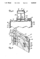
- FIG. 3 shows a sectional view taken along the line 3--3 of FIG. 2,
- FIG. 4 shows a perspective view of the end cap portion of the present invention
- FIG. 5 shows a top view of the case portion of the present invention in the open position
- FIG. 6 shows a sectional view of the case portion taken along the line 6--6 of FIG. 1,
- FIG. 7 shows a sectional view of a part of both the case and the end cap portions of the ski carrier taken along the line 7--7 of FIG. 1, and
- FIG. 8 shows a top view of the end cap portion and the case portion of an alternative embodiment of the present invention with the case portion in the open position.
- Ski carrier 12 comprises a case, 14, having a cover portion, 16, and a holder portion, 18, an end cap, 20, and two strap assemblies, 22.
- Cover portion 16, holder portion 18, and end cap 20 are each fabricated from a suitable molded polymer.
- Cover portion 16 and holder portion 18 of case 14 are shown attached to one another lying side by side in FIG. 5.
- Cover portion 16 of case 14 has the general shape of an elongated half container having a generally rectangular cover major wall, 24, a first side, 26, a second side, 28, and an end, 30.
- a handle portion, 32 protrudes from and extends along first side 26.
- Cover portion 16 also has a lip, 34, which extends beyond the edges of first side 26, end 30, and handle portion 32. No end is provided across cover major wall 24 opposite end 30, leaving an open end in cover portion 16.
- a plurality of outwardly protruding, equally spaced, elongated parallel ridges, 36, are molded into cover major wall 24, such that there are recesses in the inner surface thereof, and extend perpendicular to both first side 26 and second side 28.
- Holder portion 18 of case 14 is substantially the same size as cover portion 16 and also has the general shape of an elongated half container having a generally rectangular holder major wall, 38, a first side, 40, a second side, 42, and an end, 44. No end is provided across holder major wall 38 opposite end 44, leaving an open end in holder portion 18.
- a handle portion, 46 protrudes from and extends along first side 40.
- First side 40 and second side 42 of holder portion 18 each have two openings, 48, therein located such that those openings 48 in first side 40 are located directly opposite those openings 48 in second side 42.
- a plurality of outwardly protruding, generally rectangular supports, 52, are molded into holder major wall 38. Supports 52 are seen from the top in FIG. 5, but are better seen in FIG. 6. Each support 52 has a pad, 54, attached to an outer surface, 56, of support 52, and has a hole, 58, to permit liquid, such as melted snow, to drain from holder portion 18 of case 14.
- All holder bracket ridges 60 protrude inwardly from holder portion 18 with two pairs protruding from each of first side 40 and second side 42. All holder bracket ridges 60 are substantially perpendicular to holder major wall 38 in direction of extent, i.e. vertically oriented in FIG. 6. Members of each pair of holder bracket ridges 60 are spaced apart from one another. Two metal brackets, 62, are inserted in holder portion 18, each end of each bracket 62 being positioned in one of the spaces between a corresponding pair of holder bracket ridges 60.
- a straight side, 64, of each bracket 62 is in or near contact with holder major wall 38, a first side, 66, of each bracket is positioned between a pair of holder bracket ridges 60 protruding inward from first side 40, and a second side, 67, of each bracket is positioned between an opposing pair of holder bracket ridges 60 protruding inward from second side 42.
- Each bracket 62 has two pairs of upward extending, spaced apart columns, 68, having rectangular cross sections. Each pair of columns 68 forms between them a slot, 70, in which a pair of skis, 72, may be inserted. Columns 68 secure skis 72 between them to tend to prevent them from slapping against one another, or sliding back and forth in contact with one another, to result in scratching of ski surfaces. Also, ski poles may be wedged between columns 68 and skis 72 for transport in case 14.
- Two foam strips, 74 are attached to cover major wall 24, with each strip 74 positioned in cover portion 16 such that it is directly opposite each bracket 62 in holder portion 18 if cover portion 16 and holder portion 18 are closed against one another as shown in FIGS. 1 and 6.
- End cap 20 is shown separately in FIG. 4 rather than as assembled with case 14 as in FIG. 1 and has the general shape of a somewhat elongated container having an end opening, 76, in a first end 78.
- a second end, 84, of end cap 20 is acutely angled with respect to a cap support major wall, 86, shown in FIG. 4, and obtusely angled with respect to an opposite cap containment major wall, 88, shown in FIG. 1, to minimize the air resistance of ski carrier 12 encountered in facing forward on a moving vehicle.
- Two supports 52 are molded into cap support major wall 86. Each support 52 has a pad 54 attached to its outer surface 56 and has an opening 58 that permits liquid in end cap 20 to be drained.
- End cap 20 is shown with case 14 inserted therein in FIG. 7.
- Both cap containment major wall 88 and cap support major wall 86 have a plurality of outwardly protruding, equally spaced, elongated parallel ridges, 90, molded therein such that there are recesses, 92, in the inner surfaces thereof.
- Each recess 92 in one of these inner surfaces is directly across from a recess 92 in the other inner surface.
- Each recess 92 has a shape that permits one of ridges 36 in cover portion 16 and an opposite one of ridges 50 in holder portion 18 to be nestled therein with end cap 20 slid over the open ends of cover and holder portions 16 and 18 of case 14 so as to tend to keep end cap 20 aligned with case 14.
- a handle cap, 94 protrudes from a first side, 95, of end cap 20 and provides additional space in end cap 20 so that handle portion 32 of cover portion 16 and handle portion 46 of holder portion 18 can be received therein.
- Handle cap 94 has an end opening, 96, at a first end, 98, that is flush with first end 78 of end cap 20.
- a second end, 100, of handle cap 94 is acutely angled with respect to first side 95 of end cap 20 to minimize the air resistance of ski carrier 12 encountered in facing forward on a moving vehicle.
- End cap 20, including handle cap 94 is shown in FIG. 3 with case 14 inserted therein.
- Handle cap 94 has a cap containment side hole, 102, in a cap containment side surface, 104, and a cap support side hole, 106, in a cap support side surface, 108.
- Second side 28 of cover portion 16 is attached to second side 42 of holder portion 18 by a hinge, 110, shown in FIG. 5.
- Hinge 110 can be a flexible membrane, integrally molded to both cover portion 16 and holder portion 18, a two-part metal hinge with parts screwed into cover portion 16 and holder portion 18, or another suitable type of hinge including one allowing detachment of these portions. Hinge 110 permits cover portion 16 to be positioned with respect to holder portion 18 such that case 14 may be varied between open and closed positions.
- cover portion 16 When case 14 is in a closed position, cover portion 16 covers holder portion 18 such that lip 34 extends over the edges of first side 40, end 44, and handle portion 46 of holder portion 18. Both strips 74 attached to cover major wall 24 come into contact with any skis 72 in slots 70 and hold those skis in place.
- handle portion 32 and handle portion 46 come together to form a single composite handle, 111, shown in FIG. 1.
- case 14 is in the open position, as shown in FIG. 5, the interiors of cover portion 16 and holder portion 18 are exposed. In this open position of case 14, skis 72 may be easily inserted therein or removed therefrom.
- End opening 76 in end cap 20 and end opening 96 in handle cap 94 are large enough to permit a first end, 112, or open end, of case 14 to pass therethrough and into end cap 20 if case 14 is in the closed position. If case 14 is inserted a selected one of several predetermined distances into end cap 20, ridges 36 on cover portion 16 and ridges 50 on holder portion 18 will be nestled in corresponding recesses 92 in end cap 20, which, as stated above, aid in holding end cap 20 in place and aligned with case 14.
- ski carrier 12 can accommodate different lengths of the longest ski carried therein by selecting one of the discrete distances that first end 112 of case 14 can be inserted into end cap 20 through selecting which ridges 36,50 will be nestled in recesses 92.
- Handle 111 shown in FIG. 2, has a plurality of locking holes, 114, therein spaced along the direction of elongation of cover and holder portions 16 and 18 such that one locking hole 114 will automatically align with cap containment side hole 102 and cap support side hole 106 for each ridge-recess determined discrete distance that first end 112 of case 14 can be inserted into end cap 20.
- End cap 20 can thus be locked in place to case 14 by a bolt, 116, which is inserted through cap containment side hole 102, the selected locking hole 114, and cap support side hole 106.
- Bolt 116 having a hole therethrough perpendicular to its long direction axis at the end thereof opposite the head end, can be secured by a lock, 118, as shown in FIG.
- Each strap assembly 22 is shown in FIG. 5 and comprises a nylon (or woven metal) strap, 120, two metal hooks, 122, and a tightening buckle, 124, which may be kept within case 14 during airplane or manual transport.
- a nylon (or woven metal) strap, 120 To mount ski carrier 12 on a vehicle 10, an end of each strap 120 with its hook 122 is inserted through a corresponding opening 48 in first side 40 of holder portion 18, and the remaining end is inserted through the opposite corresponding opening 48 in second side 42 of holder portion 18.
- Ski carrier 12 can be placed on vehicle 10 such that case 14 is supported thereon by supports 52 and pads 54.
- First end 112, or the open end, of case 14 can be oriented such that it is facing forward.
- Each hook 122 can then be taken from where it emerges from its corresponding opening 48 and extended to hook to a suitable portion of vehicle 10, such as a rain gutter or door frame. Strap 120, tightened using tightening buckle 124, secures each hook 122, and therefore case 14, to vehicle 10. Case 14 can then be closed by closing cover portion 16 against holder portion 18, and end cap 20 can be slid over first end 112 of case 14. End cap 20 is then secured to case 14 using bolt 116.
- end cap 20 is removed from case 14.
- Case 14 is then opened and strap 120 loosened. All hooks 122 can then be unhooked from vehicle 10 and ski carrier 12 can be removed.
- ski carrier 12 is similar to that described above except that the dimensions of a case, 128, and an end cap, 130, are enlarged to permit ski carrier 12 to hold more equipment, including a number of ski poles, 132, and ski boots, 133.
- a metal bracket, 134, attached to holder portion, 136, of case 128 is adapted to hold ski poles 132.
- First end 112 of case 128 is inserted into end cap 130 in the same manner as described above.
Abstract
Description
Claims (16)
Priority Applications (5)
| Application Number | Priority Date | Filing Date | Title |
|---|---|---|---|
| US07/862,804 US5285942A (en) | 1992-04-03 | 1992-04-03 | Ski carrier |
| US08/022,711 US5415333A (en) | 1992-04-03 | 1993-02-24 | Ski carrier |
| CA002117686A CA2117686A1 (en) | 1992-04-03 | 1993-04-01 | Ski carrier |
| PCT/US1993/003099 WO1993019954A1 (en) | 1992-04-03 | 1993-04-01 | Ski carrier |
| AU40460/93A AU4046093A (en) | 1992-04-03 | 1993-04-01 | Ski carrier |
Applications Claiming Priority (1)
| Application Number | Priority Date | Filing Date | Title |
|---|---|---|---|
| US07/862,804 US5285942A (en) | 1992-04-03 | 1992-04-03 | Ski carrier |
Related Child Applications (1)
| Application Number | Title | Priority Date | Filing Date |
|---|---|---|---|
| US08/022,711 Continuation-In-Part US5415333A (en) | 1992-04-03 | 1993-02-24 | Ski carrier |
Publications (1)
| Publication Number | Publication Date |
|---|---|
| US5285942A true US5285942A (en) | 1994-02-15 |
Family
ID=25339402
Family Applications (1)
| Application Number | Title | Priority Date | Filing Date |
|---|---|---|---|
| US07/862,804 Expired - Fee Related US5285942A (en) | 1992-04-03 | 1992-04-03 | Ski carrier |
Country Status (1)
| Country | Link |
|---|---|
| US (1) | US5285942A (en) |
Cited By (19)
| Publication number | Priority date | Publication date | Assignee | Title |
|---|---|---|---|---|
| US5395019A (en) * | 1991-12-04 | 1995-03-07 | Christensen; David | Portable utility container with latch and mount |
| US5415333A (en) * | 1992-04-03 | 1995-05-16 | Wills; James H. | Ski carrier |
| USD381621S (en) * | 1995-08-21 | 1997-07-29 | Gary Stephen Cretcher | Canoe and luggage carrier |
| USD383111S (en) * | 1995-08-21 | 1997-09-02 | Gary Cretcher | Canoe luggage rack |
| US5713498A (en) * | 1996-06-14 | 1998-02-03 | Cucci; Charles A. | Roof top cargo container |
| US6575322B1 (en) * | 2002-12-03 | 2003-06-10 | Larry J. Brown, Jr. | Container for removable windows of a soft top vehicle |
| US20040090026A1 (en) * | 2002-11-08 | 2004-05-13 | Ball William T | Ski equipment tote |
| US20080302685A1 (en) * | 2007-06-07 | 2008-12-11 | Saucedo John J | Surfboard separating device |
| US20100228092A1 (en) * | 2009-03-06 | 2010-09-09 | Ethicon Endo-Surgery, Inc. | Surgical access devices and methods providing seal movement in predefined paths |
| US20140291976A1 (en) * | 2013-03-29 | 2014-10-02 | Brandon J. Ford | Portable Snow Sports Equipment Locker |
| US20150210221A1 (en) * | 2012-09-10 | 2015-07-30 | Thule Sweden Ab | Roof Box For A Vehicle |
| USD805148S1 (en) | 2016-03-18 | 2017-12-12 | Brandon J. Ford | Sports equipment locker |
| USD889123S1 (en) * | 2017-05-01 | 2020-07-07 | Earl McCoy | Fishing rod and reel box for vehicle roof |
| USD893178S1 (en) * | 2018-12-20 | 2020-08-18 | Lltek Motorsports Corp. | Ski box |
| US11148605B2 (en) * | 2018-08-31 | 2021-10-19 | Thule Sweden Ab | Cargo carrier |
| US11207586B1 (en) * | 2020-03-03 | 2021-12-28 | Mark Croshier | Compartmented ski carrier |
| US20230018049A1 (en) * | 2019-12-25 | 2023-01-19 | Car Mate Mfg. Co., Ltd. | Roof box |
| US20230032972A1 (en) * | 2021-07-30 | 2023-02-02 | Tony Neesham | Extendable roof top cargo carrier for a vehicle |
| US11745667B2 (en) | 2021-04-06 | 2023-09-05 | Thule, Inc. | Fishing equipment carrier |
Citations (19)
| Publication number | Priority date | Publication date | Assignee | Title |
|---|---|---|---|---|
| US2475961A (en) * | 1946-07-31 | 1949-07-12 | Charles A Heaton | Variable volume suitcase |
| US3521810A (en) * | 1968-06-21 | 1970-07-28 | Hoerner Waldorf Corp | Variable size container |
| US3744687A (en) * | 1971-08-16 | 1973-07-10 | R Oreck | Gun container |
| US3767036A (en) * | 1971-10-12 | 1973-10-23 | Leod W Mc | Lightweight container means |
| US3837548A (en) * | 1973-03-27 | 1974-09-24 | D Nerger | Ski carrying case |
| US3909031A (en) * | 1973-06-14 | 1975-09-30 | Ruth H Schmaedeke | Ski holder |
| US3921871A (en) * | 1974-12-16 | 1975-11-25 | Charles W Heil | Ski storing, protecting, and carrying apparatus |
| US4071176A (en) * | 1976-02-11 | 1978-01-31 | John Tuzee | Car top ski and ski-gear carrier |
| US4084735A (en) * | 1972-06-28 | 1978-04-18 | Nick Kappas | Ski case and rack |
| US4161268A (en) * | 1976-08-05 | 1979-07-17 | Heil Charles W | Ski storing, protecting, and carrying apparatus |
| US4171759A (en) * | 1978-07-05 | 1979-10-23 | Wnek Kenneth A | Convertible ski carrying apparatus |
| US4238063A (en) * | 1979-01-15 | 1980-12-09 | Dair Timothy J O | Ski transport container |
| US4402355A (en) * | 1981-09-11 | 1983-09-06 | Wymore Craig A | Protective container for snow skis |
| US4509656A (en) * | 1982-09-24 | 1985-04-09 | Rose-Plastic Gmbh | Variable length packing container assembly |
| US4643302A (en) * | 1985-03-15 | 1987-02-17 | Baumgardner Edward W | Container for sports equipment |
| US4860935A (en) * | 1988-03-16 | 1989-08-29 | Pavlinsky Joseph F | Apparatus and method for containing snow skis and ski poles |
| US4867361A (en) * | 1988-02-29 | 1989-09-19 | Burnham Charles R | Cartop luggage carrier |
| US4867307A (en) * | 1989-03-06 | 1989-09-19 | Bovee Dana F | Ski and pole case |
| US4953773A (en) * | 1989-08-14 | 1990-09-04 | Wirth John G | Ski carrier |
-
1992
- 1992-04-03 US US07/862,804 patent/US5285942A/en not_active Expired - Fee Related
Patent Citations (19)
| Publication number | Priority date | Publication date | Assignee | Title |
|---|---|---|---|---|
| US2475961A (en) * | 1946-07-31 | 1949-07-12 | Charles A Heaton | Variable volume suitcase |
| US3521810A (en) * | 1968-06-21 | 1970-07-28 | Hoerner Waldorf Corp | Variable size container |
| US3744687A (en) * | 1971-08-16 | 1973-07-10 | R Oreck | Gun container |
| US3767036A (en) * | 1971-10-12 | 1973-10-23 | Leod W Mc | Lightweight container means |
| US4084735A (en) * | 1972-06-28 | 1978-04-18 | Nick Kappas | Ski case and rack |
| US3837548A (en) * | 1973-03-27 | 1974-09-24 | D Nerger | Ski carrying case |
| US3909031A (en) * | 1973-06-14 | 1975-09-30 | Ruth H Schmaedeke | Ski holder |
| US3921871A (en) * | 1974-12-16 | 1975-11-25 | Charles W Heil | Ski storing, protecting, and carrying apparatus |
| US4071176A (en) * | 1976-02-11 | 1978-01-31 | John Tuzee | Car top ski and ski-gear carrier |
| US4161268A (en) * | 1976-08-05 | 1979-07-17 | Heil Charles W | Ski storing, protecting, and carrying apparatus |
| US4171759A (en) * | 1978-07-05 | 1979-10-23 | Wnek Kenneth A | Convertible ski carrying apparatus |
| US4238063A (en) * | 1979-01-15 | 1980-12-09 | Dair Timothy J O | Ski transport container |
| US4402355A (en) * | 1981-09-11 | 1983-09-06 | Wymore Craig A | Protective container for snow skis |
| US4509656A (en) * | 1982-09-24 | 1985-04-09 | Rose-Plastic Gmbh | Variable length packing container assembly |
| US4643302A (en) * | 1985-03-15 | 1987-02-17 | Baumgardner Edward W | Container for sports equipment |
| US4867361A (en) * | 1988-02-29 | 1989-09-19 | Burnham Charles R | Cartop luggage carrier |
| US4860935A (en) * | 1988-03-16 | 1989-08-29 | Pavlinsky Joseph F | Apparatus and method for containing snow skis and ski poles |
| US4867307A (en) * | 1989-03-06 | 1989-09-19 | Bovee Dana F | Ski and pole case |
| US4953773A (en) * | 1989-08-14 | 1990-09-04 | Wirth John G | Ski carrier |
Cited By (27)
| Publication number | Priority date | Publication date | Assignee | Title |
|---|---|---|---|---|
| US5395019A (en) * | 1991-12-04 | 1995-03-07 | Christensen; David | Portable utility container with latch and mount |
| US5415333A (en) * | 1992-04-03 | 1995-05-16 | Wills; James H. | Ski carrier |
| USD381621S (en) * | 1995-08-21 | 1997-07-29 | Gary Stephen Cretcher | Canoe and luggage carrier |
| USD383111S (en) * | 1995-08-21 | 1997-09-02 | Gary Cretcher | Canoe luggage rack |
| US5713498A (en) * | 1996-06-14 | 1998-02-03 | Cucci; Charles A. | Roof top cargo container |
| US20040090026A1 (en) * | 2002-11-08 | 2004-05-13 | Ball William T | Ski equipment tote |
| US8141905B2 (en) * | 2002-11-08 | 2012-03-27 | Ball William T | Ski equipment tote |
| US6575322B1 (en) * | 2002-12-03 | 2003-06-10 | Larry J. Brown, Jr. | Container for removable windows of a soft top vehicle |
| US20080302685A1 (en) * | 2007-06-07 | 2008-12-11 | Saucedo John J | Surfboard separating device |
| US7841466B2 (en) * | 2007-06-07 | 2010-11-30 | Done Right, Llc | Surfboard separating device |
| US20100228092A1 (en) * | 2009-03-06 | 2010-09-09 | Ethicon Endo-Surgery, Inc. | Surgical access devices and methods providing seal movement in predefined paths |
| US20150210221A1 (en) * | 2012-09-10 | 2015-07-30 | Thule Sweden Ab | Roof Box For A Vehicle |
| US9688210B2 (en) * | 2012-09-10 | 2017-06-27 | Thule Sweden Ab | Roof box for a vehicle |
| US20140291976A1 (en) * | 2013-03-29 | 2014-10-02 | Brandon J. Ford | Portable Snow Sports Equipment Locker |
| US10118083B2 (en) * | 2013-03-29 | 2018-11-06 | Brandon J. Ford | Portable snow sports equipment locker |
| USD805148S1 (en) | 2016-03-18 | 2017-12-12 | Brandon J. Ford | Sports equipment locker |
| USD852500S1 (en) | 2016-03-18 | 2019-07-02 | Brandon J. Ford | Portable snow sports equipment locker |
| USD889123S1 (en) * | 2017-05-01 | 2020-07-07 | Earl McCoy | Fishing rod and reel box for vehicle roof |
| US11273769B2 (en) | 2018-08-31 | 2022-03-15 | Thule Sweden Ab | Cargo carrier |
| US11148605B2 (en) * | 2018-08-31 | 2021-10-19 | Thule Sweden Ab | Cargo carrier |
| US20220266759A1 (en) * | 2018-08-31 | 2022-08-25 | Thule Sweden Ab | Cargo carrier |
| USD893178S1 (en) * | 2018-12-20 | 2020-08-18 | Lltek Motorsports Corp. | Ski box |
| US20230018049A1 (en) * | 2019-12-25 | 2023-01-19 | Car Mate Mfg. Co., Ltd. | Roof box |
| US11207586B1 (en) * | 2020-03-03 | 2021-12-28 | Mark Croshier | Compartmented ski carrier |
| US11745667B2 (en) | 2021-04-06 | 2023-09-05 | Thule, Inc. | Fishing equipment carrier |
| US20230032972A1 (en) * | 2021-07-30 | 2023-02-02 | Tony Neesham | Extendable roof top cargo carrier for a vehicle |
| US11667245B2 (en) * | 2021-07-30 | 2023-06-06 | Tony Neesham | Expendable roof top cargo carrier for a vehicle |
Similar Documents
| Publication | Publication Date | Title |
|---|---|---|
| US5285942A (en) | Ski carrier | |
| US4084735A (en) | Ski case and rack | |
| US5415333A (en) | Ski carrier | |
| US5799848A (en) | Ski carrier and case | |
| US3935977A (en) | Ski equipment carrier | |
| US5052605A (en) | Attachment arrangement for a cycle | |
| US5215234A (en) | Utility rack for vehicles | |
| EP0529062B1 (en) | Utility rack for a vehicle | |
| US4433804A (en) | Vehicle article carrier | |
| US4997116A (en) | Rear mountable carrier rack | |
| US4378898A (en) | Cargo carrier | |
| US7234619B2 (en) | Accessory strip for securing articles within a vehicle interior | |
| US6626339B2 (en) | Holder mounted bag | |
| US20070257076A1 (en) | Cargo System Attachable to a Roof Rack | |
| US4420105A (en) | Flexible hinge and closure member for a luggage carrier | |
| US4469257A (en) | Ski rack device for pickup trucks | |
| US4269340A (en) | Load bearing cross-slat | |
| US7877922B1 (en) | Fishing rod and reel storage device and carrier | |
| US5931176A (en) | Hinged tonneau cover truck tent | |
| US4779779A (en) | Luggage container accessory for detachably mounting on the exterior of a vehicle | |
| US4733809A (en) | Removable ski rack for motor vehicles | |
| US4752022A (en) | Luggage carrier for vehicles | |
| US4065092A (en) | Quick release security latch device for radio antenna base | |
| US4717055A (en) | Bracket for truck mounting ski or surfboard rack | |
| US5992720A (en) | Automotive ski rack |
Legal Events
| Date | Code | Title | Description |
|---|---|---|---|
| CC | Certificate of correction | ||
| AS | Assignment |
Owner name: IMAGE ROTOMOLDING ENTERPRISES LCC Free format text: ASSIGNMENT OF ASSIGNORS INTEREST;ASSIGNOR:WILLS, JAMES H.;REEL/FRAME:007413/0216 Effective date: 19950328 |
|
| FPAY | Fee payment |
Year of fee payment: 4 |
|
| AS | Assignment |
Owner name: HELLER FINANCIAL, INC., ILLINOIS Free format text: SECURITY INTEREST;ASSIGNOR:IMAGE ACQUISITION, INC.;REEL/FRAME:011164/0680 Effective date: 20000922 |
|
| AS | Assignment |
Owner name: IMAGE ACQUISTION, INC., ALABAMA Free format text: ASSIGNMENT OF ASSIGNORS INTEREST;ASSIGNOR:IMAGE ROTOMOLDING ENTERPRISES, INC.;REEL/FRAME:011379/0394 Effective date: 20000922 Owner name: IMAGE ROTOMOLDING ENTERPRISES, INC., MINNESOTA Free format text: ASSIGNMENT OF ASSIGNORS INTEREST;ASSIGNOR:IMAGE ROTOMOLDING ENTERPRISES, LLC, A MINNESOTA LIMITED LIABILITY COMPANY;REEL/FRAME:011379/0412 Effective date: 20000919 Owner name: IMAGE ROTOMOLDING ENTERPRISES, INC., A MINNESOTA C Free format text: ASSIGNMENT OF ASSIGNORS INTEREST;ASSIGNOR:WILLS, JAMES H.;REEL/FRAME:011379/0382 Effective date: 20000922 |
|
| AS | Assignment |
Owner name: HELLER FINANCIAL, INC., ILLINOIS Free format text: CHANGE OF NAME;ASSIGNOR:IMAGE ROTOMOLDING ENTERPRISES, INC., F/K/A IMAGE ACQUISITION, INC.;REEL/FRAME:011511/0851 Effective date: 20001005 |
|
| FPAY | Fee payment |
Year of fee payment: 8 |
|
| AS | Assignment |
Owner name: IMAGE ROTOMOLDING ENTERPRISES, INC., MINNESOTA Free format text: RELEASE OF ASSIGNMENT;ASSIGNOR:HELLER FINANCIAL, INC.;REEL/FRAME:013835/0265 Effective date: 20030307 |
|
| AS | Assignment |
Owner name: MERRILL LYNCH CAPITAL, A DIVISION OF MERRILL LYNCH Free format text: SECURITY INTEREST;ASSIGNOR:IMAGE ROTMOLDING ENTERPRISES, INC.;REEL/FRAME:013852/0785 Effective date: 20030307 |
|
| REMI | Maintenance fee reminder mailed | ||
| LAPS | Lapse for failure to pay maintenance fees | ||
| STCH | Information on status: patent discontinuation |
Free format text: PATENT EXPIRED DUE TO NONPAYMENT OF MAINTENANCE FEES UNDER 37 CFR 1.362 |
|
| FP | Lapsed due to failure to pay maintenance fee |
Effective date: 20060215 |