EP2224750A1 - Electret capacitor microphone - Google Patents
Electret capacitor microphone Download PDFInfo
- Publication number
- EP2224750A1 EP2224750A1 EP08866754A EP08866754A EP2224750A1 EP 2224750 A1 EP2224750 A1 EP 2224750A1 EP 08866754 A EP08866754 A EP 08866754A EP 08866754 A EP08866754 A EP 08866754A EP 2224750 A1 EP2224750 A1 EP 2224750A1
- Authority
- EP
- European Patent Office
- Prior art keywords
- capsule
- diaphragm
- area
- cap member
- condenser microphone
- Prior art date
- Legal status (The legal status is an assumption and is not a legal conclusion. Google has not performed a legal analysis and makes no representation as to the accuracy of the status listed.)
- Granted
Links
Images


Classifications
-
- H—ELECTRICITY
- H04—ELECTRIC COMMUNICATION TECHNIQUE
- H04R—LOUDSPEAKERS, MICROPHONES, GRAMOPHONE PICK-UPS OR LIKE ACOUSTIC ELECTROMECHANICAL TRANSDUCERS; ELECTRIC HEARING AIDS; PUBLIC ADDRESS SYSTEMS
- H04R19/00—Electrostatic transducers
- H04R19/01—Electrostatic transducers characterised by the use of electrets
- H04R19/016—Electrostatic transducers characterised by the use of electrets for microphones
-
- H—ELECTRICITY
- H04—ELECTRIC COMMUNICATION TECHNIQUE
- H04R—LOUDSPEAKERS, MICROPHONES, GRAMOPHONE PICK-UPS OR LIKE ACOUSTIC ELECTROMECHANICAL TRANSDUCERS; ELECTRIC HEARING AIDS; PUBLIC ADDRESS SYSTEMS
- H04R31/00—Apparatus or processes specially adapted for the manufacture of transducers or diaphragms therefor
- H04R31/006—Interconnection of transducer parts
-
- H—ELECTRICITY
- H04—ELECTRIC COMMUNICATION TECHNIQUE
- H04R—LOUDSPEAKERS, MICROPHONES, GRAMOPHONE PICK-UPS OR LIKE ACOUSTIC ELECTROMECHANICAL TRANSDUCERS; ELECTRIC HEARING AIDS; PUBLIC ADDRESS SYSTEMS
- H04R2499/00—Aspects covered by H04R or H04S not otherwise provided for in their subgroups
- H04R2499/10—General applications
- H04R2499/11—Transducers incorporated or for use in hand-held devices, e.g. mobile phones, PDA's, camera's
Definitions
- the present invention relates to an electret condenser microphone (referred to as an "ECM” hereinafter) comprising a capacitor section including a diaphragm, a back electrode plate arranged to face either surface of the diaphragm, and a electret layer provided on the diaphragm or the back electrode plate, all of which are housed in a capsule.
- ECM electret condenser microphone
- the ECM has been applied to a wide variety of electronic devices such as a mobile phone, a PDA and a digital camera, for example.
- the ECM is a minute element and mounted on each of the devices using surface mounting technology.
- the reflow mounting technique is used in which solder is applied on a wiring substrate to mount the ECM thereon, and then the substrate is heated and soldered.
- the reflow mounting process sometimes uses a suction-type transporting device to transport the ECM to the wiring substrate.
- Patent Document 1 Japanese Utility Model Registration No. 2548543 ( Fig. 1 )
- the portion other than the acoustic hole that is deviated from the center of gravity is drawn to transport the ECM, as a result of which it is sometimes difficult to maintain a predetermined posture of the ECM during the transportation.
- the transporting device contacts the vicinity of an edge of the top surface, the ECM easily inclines and sometimes falls off.
- a drawing force of the transporting device is increased in an attempt to solve the above problem, the top surface of the capsule is disadvantageously deformed, for example, which leaves room for improvement.
- the diaphragm may be slackened by heated air or cooling air, or polarization of the electret layer may be deteriorated by the heat.
- the conventional ECM has not adopted any effective measure to counter the heat transmission to the inner parts from heated air, cooling air or the capsule as noted above which possibly creates the problem in the reflow mounting process.
- the present invention has been made having regard to the above-noted problem, and its object is to provide an ECM suitable for suction transportation in the reflow mounting process and adopting a measure to counter the heat transmission to the inner parts from heated air, cooling air or the capsule.
- the first characteristic feature of an electret condenser microphone according to the present invention lies in comprising:
- the cap member is provided between the capsule and the capacitor section.
- the heat is alleviated by the cap member and less easily transmitted to the capacitor section.
- the capacitor section housed in the capsule is prevented from being deteriorated.
- the heat influence exerted on the electret layer provided in the capacitor section can be suppressed, which can prevent deterioration of the polarization of the electret layer caused by the heat.
- heated air or cooling air generated in the reflow mounting process pass through a passage narrowed by the opening of the capsule and a passage narrowed by the acoustic hole formed in the cap member to reach the capacitor section. This prevents the capacitor section from being damaged by heated air or cooling air generated in the reflow mounting process. More particularly, the diaphragm is prevented from slackening by heated air or cooling air.
- the suctioned portion is provided in the central portion of the top member of the capsule of the electret condenser microphone, as a result of which suction can be performed with a suction nozzle of the suction-type transporting device being aligned with the center of the top surface which substantially coincides with the center of gravity of the electret condenser microphone.
- a moment exerted on a suctioned portion when performing the suction is decreased, which reduces the drawing force of the suction-type transporting device to prevent the top surface from being deformed.
- the ECM is securely transported while the suction nozzle of the suction-type transporting device does not damage the diaphragm or the back electrode plate housed in the capsule by its suctioning action.
- the ECM suitable for suction transportation in the reflow mounting process and adopting a measure to counter the heat transmission to the inner parts from heated air, cooling air or the capsule which may pose the problem.
- a second feature of the electret condenser microphone of the present invention lies in that the acoustic hole includes arc slits surrounding the circumference of the suctioned portion.
- the acoustic hole including the openings having the predetermined areas that are arranged in the positions as close to the center of the capsule as possible, which improves the sound collecting performance.
- the slit shape of the acoustic hole provides a smaller opening width than a circular or rectangular acoustic hole having the same area, which prevents heated air, cooling air, dust or waterdrops from easily entering the capsule. As a result, the durability and reliability of the electret condenser microphone can be improved.
- the third feature of the electret condenser microphone of the present invention lies in that the cap member includes a peripheral first area and a second area defined by a central portion surrounded by the first area and projecting outward, and the suctioned portion is formed in the second area.
- the fourth feature of the electret condenser microphone of the present invention lies in that the acoustic hole is formed in the second area.
- the fifth feature of the electret condenser microphone of the present invention lies in that the acoustic hole is formed in a boundary between the first area and the second area.
- the acoustic hole is formed with a predetermined angle relative to the first area and the second area, which prevents heated air, cooling air, dust and waterdrops more reliably from entering the capsule easily.
- the suction nozzle of the transporting device is brought into contact with a position deviated from the suctioned portion, the suction nozzle would never seal the acoustic hole, which can prevent the diaphragm or the back electrode plate housed in the capsule from being damaged.
- Fig. 1 is an exploded perspective view of the ECM100
- Fig. 2 is a sectional view of the ECM100.
- the ECM100 comprises a capsule 7 consisting of a cylindrical side member 7b and a top member 7a, which includes various elements therein. Inside of the capsule 7 are housed, from the side of the top member 7a, a cap member 6, a back electrode plate 5, a spacer ring 4, a diaphragm 3, a gate ring 2, and a substrate 1.
- the side member 7b of the capsule 7 is crimped at their ends to hold the substrate 1 therein thereby fixing the various elements within the capsule 7.
- the capsule 7 is made of a conductive material such as metal.
- the cylindrical capsule 7 will be described, while the shape of the capsule 7 may be a rectangular tube.
- the back electrode pate 5, spacer ring 4, and diaphragm 3 form a capacitor section C.
- the capacitor section C detects a sound wave entering the interior of the capsule 7.
- the back electrode late 5 includes a fixed electrode 5b and an electret layer 5a mounted on a surface of the fix electrode 5b facing the diaphragm 3. Provision of the electret layer 5 allows the back electrode plate 5 to be maintained at constant potential.
- a plurality of apertures 5c are formed in the back electrode plate 5 and the electret layer 5a. The sound wave having entered the interior of the capsule 7 reaches the diaphragm 3 through the apertures 5c.
- the diaphragm 3 includes a diaphragm membrane 3b vibrated by the sound wave, and a diaphragm membrane ring 3a for holding peripheries of the diaphragm membrane 3b.
- the insulating spacer ring 4 is provided between the back electrode plate 5 and the diaphragm 3.
- An inner wall of the capsule 7 is coated with an insulating material 7c for preventing a short circuit with the various elements.
- the insulating material 7c is preferably a material having a high heat-resistance such as ceramics.
- the diaphragm 3 is electrically connected to a circuit pattern (not shown) formed on the substrate 1 through the conductive gate ring 2.
- the fixed electrode 5b of the back electrode plate 5 is electrically connected to the capsule 7 through the cap member 6, and in turn connected to the circuit pattern formed on the substrate 1 through the capsule 7.
- an IC element 9 is provided on the substrate 1 to be electrically connected to the circuit pattern.
- the capsule 7 has an opening 8 formed in the top member 7a.
- the plate-like cap member 6 is provided between the capacitor section C noted above and the top member 7a of the capsule 7.
- the cap member 6 has acoustic holes 6a formed at portions exposed to the outside through the opening 8 for introducing the sound wave into the capacitor section C.
- Fig. 3 shows a condition in which the cap member 6 is accommodated in the capsule 7, and Fig. 4 is a sectional perspective view of the cap member 6.
- the cap member 6 includes a peripheral first area 6b, and a second area 6c defined by a central portion surrounded by the first area 6b and projecting outward.
- the second area 6c formed in the central portion of the cap member 6 acts as a suctioned portion V to be drawn by a suction-type transportation device. It is enough for the suctioned portion V to have an area larger than a suction nozzle of the transportation device. This stabilizes a contacting condition between the suctioned portion V and an end face of the suction nozzle.
- the second area 6c is drawn at a center thereof to hold a portion of the ECM above the center of gravity. This can prevent the posture of the ECM100 from being changed when transported, which allows the ECM100 to fall off less easily. As a result, the drawing force of the transportation device can be reduced to prevent deformation of the capsule 7 and allows use of a small transportation device. Further, even if the cap member 6 is heated, the heat is transmitted to the capacitor section C less easily because of a space defined between the cap member 6 and the capacitor section C provided in the interior of the capsule 7.
- the acoustic holes 6a provided in the peripheries of the suctioned portion V acting as the second area 6c each have a shape of arc slit.
- Each of the acoustic holes 6a has an opening width smaller than a diameter of a conventional circular acoustic hole. This effectively prevents heated air, cooling air, dust and waterdrops from entering the interior of the capsule 7.
- the acoustic holes 6a formed in the second area 6c of the cap member 6 are formed as the arc slits defined by grooves formed in the cap member 6.
- the cap member 6 may be pushed in and bent to provide the acoustic holes 6a as the arc slits.
- the acoustic holes 6a are arranged so as not to overlap the apertures 5c of the back electrode plate 5.
- the acoustic holes 6a are blocked by the back electrode plate 5.
- the foreign substances are prevented from entering to reach the diaphragm 3 through the apertures 5c of the back electrode plate 5.
- air coming from the outside of the capsule 7 heatated air or cooling air in a reflow mounting process
- the cap member 6 is provided between the capacitor section C (back electrode plate 5) and the top member 7a of the capsule 7, which alleviates the heat transmitted to the capacitor section C through the cap member 7 even if the temperature of the capsule 7 rises.
- the capacitor section C is prevented from being adversely affected by the heat. More particularly, the heat influence exerted on the electret layer 5a provided in the capacitor section C can be reduced, which prevents polarization of the electret layer 5a from being deteriorated by the heat.
- the diaphragm 3 can be prevented from slackening by heated air or cooling air.
- the present invention is applicable to the ECM adapting the reflow mounting technology.
Landscapes
- Engineering & Computer Science (AREA)
- Physics & Mathematics (AREA)
- Acoustics & Sound (AREA)
- Signal Processing (AREA)
- Manufacturing & Machinery (AREA)
- Electrostatic, Electromagnetic, Magneto- Strictive, And Variable-Resistance Transducers (AREA)
- Details Of Audible-Bandwidth Transducers (AREA)
Abstract
Description
- The present invention relates to an electret condenser microphone (referred to as an "ECM" hereinafter) comprising a capacitor section including a diaphragm, a back electrode plate arranged to face either surface of the diaphragm, and a electret layer provided on the diaphragm or the back electrode plate, all of which are housed in a capsule.
- The ECM has been applied to a wide variety of electronic devices such as a mobile phone, a PDA and a digital camera, for example. The ECM is a minute element and mounted on each of the devices using surface mounting technology. For example, the reflow mounting technique is used in which solder is applied on a wiring substrate to mount the ECM thereon, and then the substrate is heated and soldered. In order to speed up in mounting the ECM on the wiring substrate, the reflow mounting process sometimes uses a suction-type transporting device to transport the ECM to the wiring substrate.
- Many of the conventional ECM include an acoustic hole provided in a central portion of a top surface of the capsule acting as a housing. Thus, when using the suction-type transporting device, a portion other than the acoustic hole is drawn so as not to damage the diaphragm and the like housed in the device to transport the ECM to a predetermined position on the wiring substrate.
Patent Document 1: Japanese Utility Model Registration No.2548543 Fig. 1 ) - When the conventional ECM is transported in the reflow mounting process, the portion other than the acoustic hole that is deviated from the center of gravity is drawn to transport the ECM, as a result of which it is sometimes difficult to maintain a predetermined posture of the ECM during the transportation. For example, when the transporting device contacts the vicinity of an edge of the top surface, the ECM easily inclines and sometimes falls off. On the other hand, when a drawing force of the transporting device is increased in an attempt to solve the above problem, the top surface of the capsule is disadvantageously deformed, for example, which leaves room for improvement.
- In performing the reflow mounting process, it is also required to adopt a measure against heat. In the reflow mounting process, heated air is generated and sometimes enters the capsule through the acoustic hole formed in the top surface of the capsule, or the heat coming from the heated capsule is transmitted to the inner parts (diaphragm and the electret layer, for example) of the capsule. In that case, the parts housed in the capsule may be adversely affected by the heat. In addition, cooling air for cooling the capsule enters the capsule through the acoustic hole formed in the top surface of the capsule to possibly exert an adverse influence on the parts housed in the capsule. For instance, the diaphragm may be slackened by heated air or cooling air, or polarization of the electret layer may be deteriorated by the heat.
Nonetheless, the conventional ECM has not adopted any effective measure to counter the heat transmission to the inner parts from heated air, cooling air or the capsule as noted above which possibly creates the problem in the reflow mounting process. - The present invention has been made having regard to the above-noted problem, and its object is to provide an ECM suitable for suction transportation in the reflow mounting process and adopting a measure to counter the heat transmission to the inner parts from heated air, cooling air or the capsule.
- In order to achieve the above-noted object, the first characteristic feature of an electret condenser microphone according to the present invention lies in comprising:
- a conductive capsule including an opening formed in a top member;
- a capacitor section including a diaphragm, a back electrode plate arranged to face either surface of the diaphragm, and a electret layer provided on the diaphragm or the back electrode plate, all of which are housed in the capsule; and
- a cap member provided between the capacitor section and the top member of the capsule and including an acoustic hole formed in a portion exposed to the outside through the opening;
- wherein the cap member further includes a suctioned portion formed in a central portion thereof to be drawn by a suction-type transporting device, the acoustic holes being arranged along the circumference of the suctioned portion.
- With the above-noted arrangement, the cap member is provided between the capsule and the capacitor section. Thus, even if the capsule is heated, the heat is alleviated by the cap member and less easily transmitted to the capacitor section. As a result, the capacitor section housed in the capsule is prevented from being deteriorated. In particular, the heat influence exerted on the electret layer provided in the capacitor section can be suppressed, which can prevent deterioration of the polarization of the electret layer caused by the heat.
In addition, heated air or cooling air generated in the reflow mounting process pass through a passage narrowed by the opening of the capsule and a passage narrowed by the acoustic hole formed in the cap member to reach the capacitor section. This prevents the capacitor section from being damaged by heated air or cooling air generated in the reflow mounting process. More particularly, the diaphragm is prevented from slackening by heated air or cooling air. - Further, the suctioned portion is provided in the central portion of the top member of the capsule of the electret condenser microphone, as a result of which suction can be performed with a suction nozzle of the suction-type transporting device being aligned with the center of the top surface which substantially coincides with the center of gravity of the electret condenser microphone. This changes the posture of the electret condenser microphone less easily in transportation to perform the suction reliably. In addition, a moment exerted on a suctioned portion when performing the suction is decreased, which reduces the drawing force of the suction-type transporting device to prevent the top surface from being deformed. Further, since the acoustic hole is not present in the suctioned portion provided in the top member, the ECM is securely transported while the suction nozzle of the suction-type transporting device does not damage the diaphragm or the back electrode plate housed in the capsule by its suctioning action.
As a result, it is possible to provide the ECM suitable for suction transportation in the reflow mounting process and adopting a measure to counter the heat transmission to the inner parts from heated air, cooling air or the capsule which may pose the problem. - A second feature of the electret condenser microphone of the present invention lies in that the acoustic hole includes arc slits surrounding the circumference of the suctioned portion.
- With the above-noted feature, the acoustic hole including the openings having the predetermined areas that are arranged in the positions as close to the center of the capsule as possible, which improves the sound collecting performance.
Further, the slit shape of the acoustic hole provides a smaller opening width than a circular or rectangular acoustic hole having the same area, which prevents heated air, cooling air, dust or waterdrops from easily entering the capsule. As a result, the durability and reliability of the electret condenser microphone can be improved. - The third feature of the electret condenser microphone of the present invention lies in that the cap member includes a peripheral first area and a second area defined by a central portion surrounded by the first area and projecting outward, and the suctioned portion is formed in the second area.
- With the above arrangement, a space is provided between the cap member and the capacitor section housed in the capsule. As a result, even if the cap member is heated, the heat is transmitted to the capacitor section less easily.
- The fourth feature of the electret condenser microphone of the present invention lies in that the acoustic hole is formed in the second area.
- With the above arrangement, since the acoustic hole is formed in the second area projecting outward, a sound wave can be satisfactorily taken in through the acoustic hole from the outside.
- The fifth feature of the electret condenser microphone of the present invention lies in that the acoustic hole is formed in a boundary between the first area and the second area.
- With the above arrangement, the acoustic hole is formed with a predetermined angle relative to the first area and the second area, which prevents heated air, cooling air, dust and waterdrops more reliably from entering the capsule easily.
In addition, even if the suction nozzle of the transporting device is brought into contact with a position deviated from the suctioned portion, the suction nozzle would never seal the acoustic hole, which can prevent the diaphragm or the back electrode plate housed in the capsule from being damaged. -
-
Fig. 1 is an exploded perspective view of an electret condenser microphone; -
Fig. 2 is a sectional view of the electret condenser microphone; -
Fig. 3 shows a condition in which a cap member is housed in a capsule; -
Fig. 4 is a sectional perspective view (1) of the cap member; -
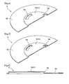
Fig. 5 is a sectional perspective view (2) of the cap member; and -
Fig. 6 is a sectional view of the cap member in accordance with a modified embodiment. - An electret condenser microphone (referred to as an "ECM" hereinafter) of the present invention will be described hereinafter in reference to the accompanying drawings.
Fig. 1 is an exploded perspective view of the ECM100, andFig. 2 is a sectional view of the ECM100. - As shown in
Figs. 1 and2 , the ECM100 comprises acapsule 7 consisting of acylindrical side member 7b and atop member 7a, which includes various elements therein. Inside of thecapsule 7 are housed, from the side of thetop member 7a, acap member 6, aback electrode plate 5, aspacer ring 4, adiaphragm 3, agate ring 2, and asubstrate 1. Theside member 7b of thecapsule 7 is crimped at their ends to hold thesubstrate 1 therein thereby fixing the various elements within thecapsule 7. Thecapsule 7 is made of a conductive material such as metal.
In the current embodiment, thecylindrical capsule 7 will be described, while the shape of thecapsule 7 may be a rectangular tube. - In the current embodiment, the
back electrode pate 5,spacer ring 4, anddiaphragm 3 form a capacitor section C. The capacitor section C detects a sound wave entering the interior of thecapsule 7. The back electrode late 5 includes a fixedelectrode 5b and anelectret layer 5a mounted on a surface of thefix electrode 5b facing thediaphragm 3. Provision of theelectret layer 5 allows theback electrode plate 5 to be maintained at constant potential. A plurality ofapertures 5c are formed in theback electrode plate 5 and theelectret layer 5a. The sound wave having entered the interior of thecapsule 7 reaches thediaphragm 3 through theapertures 5c. - The
diaphragm 3 includes adiaphragm membrane 3b vibrated by the sound wave, and adiaphragm membrane ring 3a for holding peripheries of thediaphragm membrane 3b. The insulatingspacer ring 4 is provided between theback electrode plate 5 and thediaphragm 3. An inner wall of thecapsule 7 is coated with an insulatingmaterial 7c for preventing a short circuit with the various elements. In order to prevent heat damage of the various elements housed in thecapsule 7, the insulatingmaterial 7c is preferably a material having a high heat-resistance such as ceramics. - The
diaphragm 3 is electrically connected to a circuit pattern (not shown) formed on thesubstrate 1 through theconductive gate ring 2. The fixedelectrode 5b of theback electrode plate 5 is electrically connected to thecapsule 7 through thecap member 6, and in turn connected to the circuit pattern formed on thesubstrate 1 through thecapsule 7. Further, anIC element 9 is provided on thesubstrate 1 to be electrically connected to the circuit pattern.
With the above-noted arrangement, when thediaphragm membrane 3b receives the sound wave and vibrates, displacement of thediaphragm 3b is transmitted to theIC element 9 as a change in capacitance of the capacitor section C (backelectrode plate 5 and diaphragm 3). That means that the sound wave is converted to an electric signal at the ECM100. - The
capsule 7 has anopening 8 formed in thetop member 7a. The plate-like cap member 6 is provided between the capacitor section C noted above and thetop member 7a of thecapsule 7. Thecap member 6 hasacoustic holes 6a formed at portions exposed to the outside through theopening 8 for introducing the sound wave into the capacitor section C. -
Fig. 3 shows a condition in which thecap member 6 is accommodated in thecapsule 7, andFig. 4 is a sectional perspective view of thecap member 6. As shown, thecap member 6 includes a peripheralfirst area 6b, and asecond area 6c defined by a central portion surrounded by thefirst area 6b and projecting outward. Thesecond area 6c formed in the central portion of thecap member 6 acts as a suctioned portion V to be drawn by a suction-type transportation device. It is enough for the suctioned portion V to have an area larger than a suction nozzle of the transportation device. This stabilizes a contacting condition between the suctioned portion V and an end face of the suction nozzle.
When the ECM100 is transported in a horizontal posture, thesecond area 6c is drawn at a center thereof to hold a portion of the ECM above the center of gravity. This can prevent the posture of the ECM100 from being changed when transported, which allows the ECM100 to fall off less easily. As a result, the drawing force of the transportation device can be reduced to prevent deformation of thecapsule 7 and allows use of a small transportation device.
Further, even if thecap member 6 is heated, the heat is transmitted to the capacitor section C less easily because of a space defined between thecap member 6 and the capacitor section C provided in the interior of thecapsule 7. - The
acoustic holes 6a provided in the peripheries of the suctioned portion V acting as thesecond area 6c each have a shape of arc slit. Each of theacoustic holes 6a has an opening width smaller than a diameter of a conventional circular acoustic hole. This effectively prevents heated air, cooling air, dust and waterdrops from entering the interior of thecapsule 7. More particularly, theacoustic holes 6a formed in thesecond area 6c of thecap member 6 are formed as the arc slits defined by grooves formed in thecap member 6. Alternatively, as shown inFig. 5 , thecap member 6 may be pushed in and bent to provide theacoustic holes 6a as the arc slits. - As shown in
Fig. 2 , in the ECM100 of the current embodiment, theacoustic holes 6a are arranged so as not to overlap theapertures 5c of theback electrode plate 5. Thus, even if foreign substances enter through theacoustic holes 6a, they are blocked by theback electrode plate 5. In other words, the foreign substances are prevented from entering to reach thediaphragm 3 through theapertures 5c of theback electrode plate 5. Further, air coming from the outside of the capsule 7 (heated air or cooling air in a reflow mounting process) is prevented from blowing directly against thediaphragm membrane 3b. In addition, thecap member 6 is provided between the capacitor section C (back electrode plate 5) and thetop member 7a of thecapsule 7, which alleviates the heat transmitted to the capacitor section C through thecap member 7 even if the temperature of thecapsule 7 rises.
As a result, the capacitor section C is prevented from being adversely affected by the heat. More particularly, the heat influence exerted on theelectret layer 5a provided in the capacitor section C can be reduced, which prevents polarization of theelectret layer 5a from being deteriorated by the heat. In addition, thediaphragm 3 can be prevented from slackening by heated air or cooling air. -
- <1> The design of the capacitor section C may vary as desired. For example, in the above-noted embodiment, the
back electrode plate 5 is provided close to thecap member 6 in the capacitor section C housed in thecapsule 7. Instead, thediaphragm 3 may be provided close to thecap member 6. Further, the diaphragm may include the electret layer, though the back electrode plate includes the electret layer in the above-noted embodiment. -
- <2> The
acoustic holes 6a are arc slits in the above-noted embodiment. The shape or arrangement of theacoustic holes 6a may vary as desired. For example, theacoustic holes 6a may be a plurality of fine circular holes or rectangular holes continuously arranged in arc. Such an arrangement of the acoustic holes performs substantially the same function as theacoustic holes 6a comprising the arc slits.
Alternatively, the plurality of fine circular holes or rectangular holes noted above may be continuously arranged in a ring shape. Instead, the shape of theacoustic holes 6a may be arc slits, curved slits, straight slits or zigzag slits that are distributed radially from the center. -
- <3> The position where the acoustic holes are formed may be changed. For example, as shown in
Fig. 6 , theacoustic holes 6a may be formed in a boundary between the first area and the second area of the cap member. In this way, theacoustic holes 6a are formed with a predetermined angle relative to thefirst area 6b and thesecond area 6c, which prevents heated air, cooling air, dust and waterdrops more reliably from entering thecapsule 7 easily, than the arrangement where theacoustic holes 6a are provided in thefirst area 6b or thesecond area 6c. This can improve durability and reliability of the ECM100.
In addition, even if the suction nozzle of the transporting device is brought into contact with a position deviated from the suctioned portion V, the suction nozzle would never seal theacoustic holes 6a, which can prevent thediaphragm 3 or theback electrode plate 5 arranged in thecapsule 7 from being damaged. - The present invention is applicable to the ECM adapting the reflow mounting technology.
Claims (5)
- An electret condenser microphone comprising:a conductive capsule including an opening formed in a top member;a capacitor section including a diaphragm, a back electrode plate arranged to face either surface of the diaphragm, and a electret layer provided on the diaphragm or the back electrode plate, all of which are housed in the capsule; anda cap member provided between the capacitor section and the top member of the capsule and including an acoustic hole formed in a portion exposed to the outside through the opening;wherein the cap member further includes a suctioned portion formed in a central portion thereof to be drawn by a suction-type transporting device, the acoustic holes being arranged along the circumference of the suctioned portion.
- The electret condenser microphone as defined in claim 1 wherein the acoustic hole includes arc slits surrounding the circumference of the suctioned portion.
- The electret condenser microphone as defined in claim 1 or 2, wherein the cap member includes a peripheral first area and a second area defined by a central portion surrounded by the first area and projecting outward, and the suctioned portion is formed in the second area.
- The electret condenser microphone as defined in claim 3 wherein the acoustic hole is formed in the second area.
- The electret condenser microphone as defined in claim 3 wherein the acoustic hole is formed in a boundary between the first area and the second area.
Applications Claiming Priority (2)
| Application Number | Priority Date | Filing Date | Title |
|---|---|---|---|
| JP2007337235A JP4944760B2 (en) | 2007-12-27 | 2007-12-27 | Electret condenser microphone |
| PCT/JP2008/070013 WO2009084321A1 (en) | 2007-12-27 | 2008-11-04 | Electret capacitor microphone |
Publications (3)
| Publication Number | Publication Date |
|---|---|
| EP2224750A1 true EP2224750A1 (en) | 2010-09-01 |
| EP2224750A4 EP2224750A4 (en) | 2011-02-23 |
| EP2224750B1 EP2224750B1 (en) | 2012-03-28 |
Family
ID=40824044
Family Applications (1)
| Application Number | Title | Priority Date | Filing Date |
|---|---|---|---|
| EP08866754A Active EP2224750B1 (en) | 2007-12-27 | 2008-11-04 | Electret condenser microphone |
Country Status (8)
| Country | Link |
|---|---|
| US (1) | US20110013788A1 (en) |
| EP (1) | EP2224750B1 (en) |
| JP (1) | JP4944760B2 (en) |
| KR (1) | KR101510167B1 (en) |
| CN (1) | CN101911729A (en) |
| AT (1) | ATE551845T1 (en) |
| TW (1) | TW200932023A (en) |
| WO (1) | WO2009084321A1 (en) |
Cited By (1)
| Publication number | Priority date | Publication date | Assignee | Title |
|---|---|---|---|---|
| US8842858B2 (en) | 2012-06-21 | 2014-09-23 | Invensense, Inc. | Electret condenser microphone |
Families Citing this family (8)
| Publication number | Priority date | Publication date | Assignee | Title |
|---|---|---|---|---|
| US9693135B2 (en) * | 2012-01-05 | 2017-06-27 | Tdk Corporation | Differential microphone and method for driving a differential microphone |
| JP6145459B2 (en) * | 2012-01-09 | 2017-06-14 | ヤン ル ペング | Microphone module having feedback suppression and feedback suppression method |
| DE102012219915A1 (en) * | 2012-10-31 | 2014-04-30 | Sennheiser Electronic Gmbh & Co. Kg | Method of making a condenser microphone and condenser microphone |
| EP2731129A1 (en) * | 2012-11-07 | 2014-05-14 | ams AG | Molded semiconductor sensor device and method of producing the same at a wafer-level |
| TWI462599B (en) * | 2012-12-25 | 2014-11-21 | Ind Tech Res Inst | A earphone-microphone with single electret structure |
| CN105691658A (en) * | 2016-04-07 | 2016-06-22 | 陈建荣 | Donkey-hide glue capsule counting and bottling machine |
| EP3544317B1 (en) * | 2018-03-22 | 2024-10-30 | Austrian Audio GmbH | Condenser microphone with ring made of ceramic |
| US12292348B2 (en) * | 2021-10-20 | 2025-05-06 | Merry Electronics(Shezhen) Co., Ltd. | Electronic device |
Family Cites Families (13)
| Publication number | Priority date | Publication date | Assignee | Title |
|---|---|---|---|---|
| SE362571B (en) * | 1971-12-02 | 1973-12-10 | Ericsson Telefon Ab L M | |
| JPS5223966Y2 (en) * | 1974-10-31 | 1977-05-31 | ||
| JP2548543B2 (en) | 1985-08-28 | 1996-10-30 | コンチネンタル−ワ−ト エレクトロニクス コ−ポレイシヨン | Insulation connection device for double wire flat cable |
| DE3700594A1 (en) * | 1986-01-16 | 1987-07-23 | Akg Akustische Kino Geraete | PRESSURE GRADIENT RECEIVER |
| JPH02149199A (en) * | 1988-11-30 | 1990-06-07 | Matsushita Electric Ind Co Ltd | electret condenser microphone |
| US5272758A (en) * | 1991-09-09 | 1993-12-21 | Hosiden Corporation | Electret condenser microphone unit |
| JP2003102096A (en) * | 2001-09-20 | 2003-04-04 | Hosiden Corp | Electret condenser microphone |
| JP3908059B2 (en) * | 2002-02-27 | 2007-04-25 | スター精密株式会社 | Electret condenser microphone |
| EP1494503A4 (en) * | 2002-04-05 | 2009-09-23 | Panasonic Corp | Capacitor sensor |
| JP4188325B2 (en) * | 2005-02-09 | 2008-11-26 | ホシデン株式会社 | Microphone with built-in dustproof plate |
| JP4150407B2 (en) * | 2005-06-20 | 2008-09-17 | ホシデン株式会社 | Electroacoustic transducer |
| JP2007295308A (en) * | 2006-04-25 | 2007-11-08 | Citizen Electronics Co Ltd | Method of manufacturing electret capaciter microphone |
| JP4850086B2 (en) * | 2007-02-14 | 2012-01-11 | パナソニック株式会社 | MEMS microphone device |
-
2007
- 2007-12-27 JP JP2007337235A patent/JP4944760B2/en active Active
-
2008
- 2008-11-04 US US12/810,082 patent/US20110013788A1/en not_active Abandoned
- 2008-11-04 AT AT08866754T patent/ATE551845T1/en active
- 2008-11-04 WO PCT/JP2008/070013 patent/WO2009084321A1/en not_active Ceased
- 2008-11-04 KR KR1020107012676A patent/KR101510167B1/en active Active
- 2008-11-04 CN CN2008801236283A patent/CN101911729A/en active Pending
- 2008-11-04 EP EP08866754A patent/EP2224750B1/en active Active
- 2008-11-11 TW TW097143503A patent/TW200932023A/en unknown
Non-Patent Citations (2)
| Title |
|---|
| No further relevant documents disclosed * |
| See also references of WO2009084321A1 * |
Cited By (1)
| Publication number | Priority date | Publication date | Assignee | Title |
|---|---|---|---|---|
| US8842858B2 (en) | 2012-06-21 | 2014-09-23 | Invensense, Inc. | Electret condenser microphone |
Also Published As
| Publication number | Publication date |
|---|---|
| ATE551845T1 (en) | 2012-04-15 |
| TWI373974B (en) | 2012-10-01 |
| KR20100096153A (en) | 2010-09-01 |
| JP2009159463A (en) | 2009-07-16 |
| EP2224750B1 (en) | 2012-03-28 |
| WO2009084321A1 (en) | 2009-07-09 |
| KR101510167B1 (en) | 2015-04-08 |
| CN101911729A (en) | 2010-12-08 |
| EP2224750A4 (en) | 2011-02-23 |
| US20110013788A1 (en) | 2011-01-20 |
| TW200932023A (en) | 2009-07-16 |
| JP4944760B2 (en) | 2012-06-06 |
Similar Documents
| Publication | Publication Date | Title |
|---|---|---|
| EP2224750B1 (en) | Electret condenser microphone | |
| JP4779002B2 (en) | MEMS microphone package with sound holes in PCB | |
| TWI306720B (en) | ||
| KR100673849B1 (en) | Condenser microphone mounted on main board and mobile communication terminal including the same | |
| JP3921209B2 (en) | Method for mounting condenser microphone and condenser microphone | |
| JP4777406B2 (en) | MEMS microphone package | |
| US8041064B2 (en) | Card type MEMS microphone | |
| US7907743B2 (en) | Electro-acoustic transducer | |
| US20050089188A1 (en) | High performance capacitor microphone and manufacturing method thereof | |
| US8135150B2 (en) | Electret condensor microphone | |
| US10616687B2 (en) | Microphone and manufacturing method thereof | |
| EP1569498A3 (en) | Parallelepiped condenser microphone | |
| JP5097603B2 (en) | Microphone unit | |
| JP2004207807A (en) | Microphone device and its microphone and holder | |
| KR100644730B1 (en) | Silicon condenser microphone | |
| KR100406256B1 (en) | Microphone including printed circuit board having protrusion portion for electrical contact and Method of connecting for it to outer apparatus | |
| KR200256710Y1 (en) | Pin type Connecter of microphone | |
| EP1513370A2 (en) | Condenser microphone | |
| KR20170004430A (en) | Microphone package | |
| KR100720837B1 (en) | Pin type electrode and condenser microphone having the same | |
| EP1874087B1 (en) | Electret condenser microphone | |
| KR101731041B1 (en) | Microphone package | |
| KR20020042593A (en) | Pin type Connecter of microphone |
Legal Events
| Date | Code | Title | Description |
|---|---|---|---|
| PUAI | Public reference made under article 153(3) epc to a published international application that has entered the european phase |
Free format text: ORIGINAL CODE: 0009012 |
|
| 17P | Request for examination filed |
Effective date: 20100604 |
|
| AK | Designated contracting states |
Kind code of ref document: A1 Designated state(s): AT BE BG CH CY CZ DE DK EE ES FI FR GB GR HR HU IE IS IT LI LT LU LV MC MT NL NO PL PT RO SE SI SK TR |
|
| AX | Request for extension of the european patent |
Extension state: AL BA MK RS |
|
| A4 | Supplementary search report drawn up and despatched |
Effective date: 20110124 |
|
| DAX | Request for extension of the european patent (deleted) | ||
| GRAP | Despatch of communication of intention to grant a patent |
Free format text: ORIGINAL CODE: EPIDOSNIGR1 |
|
| RTI1 | Title (correction) |
Free format text: ELECTRET CONDENSER MICROPHONE |
|
| GRAS | Grant fee paid |
Free format text: ORIGINAL CODE: EPIDOSNIGR3 |
|
| GRAA | (expected) grant |
Free format text: ORIGINAL CODE: 0009210 |
|
| AK | Designated contracting states |
Kind code of ref document: B1 Designated state(s): AT BE BG CH CY CZ DE DK EE ES FI FR GB GR HR HU IE IS IT LI LT LU LV MC MT NL NO PL PT RO SE SI SK TR |
|
| REG | Reference to a national code |
Ref country code: GB Ref legal event code: FG4D |
|
| REG | Reference to a national code |
Ref country code: CH Ref legal event code: EP |
|
| REG | Reference to a national code |
Ref country code: AT Ref legal event code: REF Ref document number: 551845 Country of ref document: AT Kind code of ref document: T Effective date: 20120415 |
|
| REG | Reference to a national code |
Ref country code: IE Ref legal event code: FG4D |
|
| REG | Reference to a national code |
Ref country code: DE Ref legal event code: R096 Ref document number: 602008014535 Country of ref document: DE Effective date: 20120524 |
|
| REG | Reference to a national code |
Ref country code: NL Ref legal event code: VDEP Effective date: 20120328 |
|
| REG | Reference to a national code |
Ref country code: SE Ref legal event code: TRGR |
|
| PG25 | Lapsed in a contracting state [announced via postgrant information from national office to epo] |
Ref country code: NO Free format text: LAPSE BECAUSE OF FAILURE TO SUBMIT A TRANSLATION OF THE DESCRIPTION OR TO PAY THE FEE WITHIN THE PRESCRIBED TIME-LIMIT Effective date: 20120628 Ref country code: LT Free format text: LAPSE BECAUSE OF FAILURE TO SUBMIT A TRANSLATION OF THE DESCRIPTION OR TO PAY THE FEE WITHIN THE PRESCRIBED TIME-LIMIT Effective date: 20120328 Ref country code: HR Free format text: LAPSE BECAUSE OF FAILURE TO SUBMIT A TRANSLATION OF THE DESCRIPTION OR TO PAY THE FEE WITHIN THE PRESCRIBED TIME-LIMIT Effective date: 20120328 |
|
| LTIE | Lt: invalidation of european patent or patent extension |
Effective date: 20120328 |
|
| PG25 | Lapsed in a contracting state [announced via postgrant information from national office to epo] |
Ref country code: GR Free format text: LAPSE BECAUSE OF FAILURE TO SUBMIT A TRANSLATION OF THE DESCRIPTION OR TO PAY THE FEE WITHIN THE PRESCRIBED TIME-LIMIT Effective date: 20120629 Ref country code: LV Free format text: LAPSE BECAUSE OF FAILURE TO SUBMIT A TRANSLATION OF THE DESCRIPTION OR TO PAY THE FEE WITHIN THE PRESCRIBED TIME-LIMIT Effective date: 20120328 |
|
| REG | Reference to a national code |
Ref country code: AT Ref legal event code: MK05 Ref document number: 551845 Country of ref document: AT Kind code of ref document: T Effective date: 20120328 |
|
| PG25 | Lapsed in a contracting state [announced via postgrant information from national office to epo] |
Ref country code: CY Free format text: LAPSE BECAUSE OF FAILURE TO SUBMIT A TRANSLATION OF THE DESCRIPTION OR TO PAY THE FEE WITHIN THE PRESCRIBED TIME-LIMIT Effective date: 20120328 |
|
| PG25 | Lapsed in a contracting state [announced via postgrant information from national office to epo] |
Ref country code: BE Free format text: LAPSE BECAUSE OF FAILURE TO SUBMIT A TRANSLATION OF THE DESCRIPTION OR TO PAY THE FEE WITHIN THE PRESCRIBED TIME-LIMIT Effective date: 20120328 Ref country code: IS Free format text: LAPSE BECAUSE OF FAILURE TO SUBMIT A TRANSLATION OF THE DESCRIPTION OR TO PAY THE FEE WITHIN THE PRESCRIBED TIME-LIMIT Effective date: 20120728 Ref country code: PL Free format text: LAPSE BECAUSE OF FAILURE TO SUBMIT A TRANSLATION OF THE DESCRIPTION OR TO PAY THE FEE WITHIN THE PRESCRIBED TIME-LIMIT Effective date: 20120328 Ref country code: RO Free format text: LAPSE BECAUSE OF FAILURE TO SUBMIT A TRANSLATION OF THE DESCRIPTION OR TO PAY THE FEE WITHIN THE PRESCRIBED TIME-LIMIT Effective date: 20120328 Ref country code: SI Free format text: LAPSE BECAUSE OF FAILURE TO SUBMIT A TRANSLATION OF THE DESCRIPTION OR TO PAY THE FEE WITHIN THE PRESCRIBED TIME-LIMIT Effective date: 20120328 Ref country code: CZ Free format text: LAPSE BECAUSE OF FAILURE TO SUBMIT A TRANSLATION OF THE DESCRIPTION OR TO PAY THE FEE WITHIN THE PRESCRIBED TIME-LIMIT Effective date: 20120328 Ref country code: EE Free format text: LAPSE BECAUSE OF FAILURE TO SUBMIT A TRANSLATION OF THE DESCRIPTION OR TO PAY THE FEE WITHIN THE PRESCRIBED TIME-LIMIT Effective date: 20120328 |
|
| PG25 | Lapsed in a contracting state [announced via postgrant information from national office to epo] |
Ref country code: SK Free format text: LAPSE BECAUSE OF FAILURE TO SUBMIT A TRANSLATION OF THE DESCRIPTION OR TO PAY THE FEE WITHIN THE PRESCRIBED TIME-LIMIT Effective date: 20120328 Ref country code: PT Free format text: LAPSE BECAUSE OF FAILURE TO SUBMIT A TRANSLATION OF THE DESCRIPTION OR TO PAY THE FEE WITHIN THE PRESCRIBED TIME-LIMIT Effective date: 20120730 |
|
| PG25 | Lapsed in a contracting state [announced via postgrant information from national office to epo] |
Ref country code: NL Free format text: LAPSE BECAUSE OF FAILURE TO SUBMIT A TRANSLATION OF THE DESCRIPTION OR TO PAY THE FEE WITHIN THE PRESCRIBED TIME-LIMIT Effective date: 20120328 Ref country code: AT Free format text: LAPSE BECAUSE OF FAILURE TO SUBMIT A TRANSLATION OF THE DESCRIPTION OR TO PAY THE FEE WITHIN THE PRESCRIBED TIME-LIMIT Effective date: 20120328 Ref country code: DK Free format text: LAPSE BECAUSE OF FAILURE TO SUBMIT A TRANSLATION OF THE DESCRIPTION OR TO PAY THE FEE WITHIN THE PRESCRIBED TIME-LIMIT Effective date: 20120328 |
|
| PLBE | No opposition filed within time limit |
Free format text: ORIGINAL CODE: 0009261 |
|
| STAA | Information on the status of an ep patent application or granted ep patent |
Free format text: STATUS: NO OPPOSITION FILED WITHIN TIME LIMIT |
|
| PG25 | Lapsed in a contracting state [announced via postgrant information from national office to epo] |
Ref country code: IT Free format text: LAPSE BECAUSE OF FAILURE TO SUBMIT A TRANSLATION OF THE DESCRIPTION OR TO PAY THE FEE WITHIN THE PRESCRIBED TIME-LIMIT Effective date: 20120328 |
|
| 26N | No opposition filed |
Effective date: 20130103 |
|
| REG | Reference to a national code |
Ref country code: DE Ref legal event code: R097 Ref document number: 602008014535 Country of ref document: DE Effective date: 20130103 |
|
| PG25 | Lapsed in a contracting state [announced via postgrant information from national office to epo] |
Ref country code: ES Free format text: LAPSE BECAUSE OF FAILURE TO SUBMIT A TRANSLATION OF THE DESCRIPTION OR TO PAY THE FEE WITHIN THE PRESCRIBED TIME-LIMIT Effective date: 20120709 |
|
| REG | Reference to a national code |
Ref country code: CH Ref legal event code: PL |
|
| GBPC | Gb: european patent ceased through non-payment of renewal fee |
Effective date: 20121104 |
|
| PG25 | Lapsed in a contracting state [announced via postgrant information from national office to epo] |
Ref country code: CH Free format text: LAPSE BECAUSE OF NON-PAYMENT OF DUE FEES Effective date: 20121130 Ref country code: LI Free format text: LAPSE BECAUSE OF NON-PAYMENT OF DUE FEES Effective date: 20121130 Ref country code: BG Free format text: LAPSE BECAUSE OF FAILURE TO SUBMIT A TRANSLATION OF THE DESCRIPTION OR TO PAY THE FEE WITHIN THE PRESCRIBED TIME-LIMIT Effective date: 20120628 |
|
| REG | Reference to a national code |
Ref country code: IE Ref legal event code: MM4A |
|
| PG25 | Lapsed in a contracting state [announced via postgrant information from national office to epo] |
Ref country code: IE Free format text: LAPSE BECAUSE OF NON-PAYMENT OF DUE FEES Effective date: 20121104 |
|
| PG25 | Lapsed in a contracting state [announced via postgrant information from national office to epo] |
Ref country code: GB Free format text: LAPSE BECAUSE OF NON-PAYMENT OF DUE FEES Effective date: 20121104 Ref country code: MT Free format text: LAPSE BECAUSE OF FAILURE TO SUBMIT A TRANSLATION OF THE DESCRIPTION OR TO PAY THE FEE WITHIN THE PRESCRIBED TIME-LIMIT Effective date: 20120328 |
|
| PG25 | Lapsed in a contracting state [announced via postgrant information from national office to epo] |
Ref country code: TR Free format text: LAPSE BECAUSE OF FAILURE TO SUBMIT A TRANSLATION OF THE DESCRIPTION OR TO PAY THE FEE WITHIN THE PRESCRIBED TIME-LIMIT Effective date: 20120328 Ref country code: MC Free format text: LAPSE BECAUSE OF NON-PAYMENT OF DUE FEES Effective date: 20121130 |
|
| PG25 | Lapsed in a contracting state [announced via postgrant information from national office to epo] |
Ref country code: LU Free format text: LAPSE BECAUSE OF NON-PAYMENT OF DUE FEES Effective date: 20121104 |
|
| PG25 | Lapsed in a contracting state [announced via postgrant information from national office to epo] |
Ref country code: HU Free format text: LAPSE BECAUSE OF FAILURE TO SUBMIT A TRANSLATION OF THE DESCRIPTION OR TO PAY THE FEE WITHIN THE PRESCRIBED TIME-LIMIT Effective date: 20081104 |
|
| REG | Reference to a national code |
Ref country code: FR Ref legal event code: PLFP Year of fee payment: 8 |
|
| REG | Reference to a national code |
Ref country code: FR Ref legal event code: PLFP Year of fee payment: 9 |
|
| REG | Reference to a national code |
Ref country code: FR Ref legal event code: PLFP Year of fee payment: 10 |
|
| REG | Reference to a national code |
Ref country code: FR Ref legal event code: PLFP Year of fee payment: 11 |
|
| PGFP | Annual fee paid to national office [announced via postgrant information from national office to epo] |
Ref country code: DE Payment date: 20251023 Year of fee payment: 18 |
|
| PGFP | Annual fee paid to national office [announced via postgrant information from national office to epo] |
Ref country code: FI Payment date: 20251103 Year of fee payment: 18 |
|
| PGFP | Annual fee paid to national office [announced via postgrant information from national office to epo] |
Ref country code: FR Payment date: 20251121 Year of fee payment: 18 |
|
| PGFP | Annual fee paid to national office [announced via postgrant information from national office to epo] |
Ref country code: SE Payment date: 20251103 Year of fee payment: 18 |