EP2224724A2 - Procédé de codage et de décodage utilisant un échantillonnage du résidue - Google Patents
Procédé de codage et de décodage utilisant un échantillonnage du résidue Download PDFInfo
- Publication number
- EP2224724A2 EP2224724A2 EP20100165464 EP10165464A EP2224724A2 EP 2224724 A2 EP2224724 A2 EP 2224724A2 EP 20100165464 EP20100165464 EP 20100165464 EP 10165464 A EP10165464 A EP 10165464A EP 2224724 A2 EP2224724 A2 EP 2224724A2
- Authority
- EP
- European Patent Office
- Prior art keywords
- image
- residue
- data
- unit
- original image
- Prior art date
- Legal status (The legal status is an assumption and is not a legal conclusion. Google has not performed a legal analysis and makes no representation as to the accuracy of the status listed.)
- Withdrawn
Links
Images


Classifications
-
- H—ELECTRICITY
- H04—ELECTRIC COMMUNICATION TECHNIQUE
- H04N—PICTORIAL COMMUNICATION, e.g. TELEVISION
- H04N1/00—Scanning, transmission or reproduction of documents or the like, e.g. facsimile transmission; Details thereof
- H04N1/46—Colour picture communication systems
- H04N1/64—Systems for the transmission or the storage of the colour picture signal; Details therefor, e.g. coding or decoding means therefor
- H04N1/646—Transmitting or storing colour television type signals, e.g. PAL, Lab; Their conversion into additive or subtractive colour signals or vice versa therefor
-
- H—ELECTRICITY
- H04—ELECTRIC COMMUNICATION TECHNIQUE
- H04N—PICTORIAL COMMUNICATION, e.g. TELEVISION
- H04N19/00—Methods or arrangements for coding, decoding, compressing or decompressing digital video signals
- H04N19/10—Methods or arrangements for coding, decoding, compressing or decompressing digital video signals using adaptive coding
- H04N19/102—Methods or arrangements for coding, decoding, compressing or decompressing digital video signals using adaptive coding characterised by the element, parameter or selection affected or controlled by the adaptive coding
- H04N19/103—Selection of coding mode or of prediction mode
- H04N19/105—Selection of the reference unit for prediction within a chosen coding or prediction mode, e.g. adaptive choice of position and number of pixels used for prediction
-
- H—ELECTRICITY
- H04—ELECTRIC COMMUNICATION TECHNIQUE
- H04N—PICTORIAL COMMUNICATION, e.g. TELEVISION
- H04N19/00—Methods or arrangements for coding, decoding, compressing or decompressing digital video signals
- H04N19/10—Methods or arrangements for coding, decoding, compressing or decompressing digital video signals using adaptive coding
- H04N19/102—Methods or arrangements for coding, decoding, compressing or decompressing digital video signals using adaptive coding characterised by the element, parameter or selection affected or controlled by the adaptive coding
- H04N19/132—Sampling, masking or truncation of coding units, e.g. adaptive resampling, frame skipping, frame interpolation or high-frequency transform coefficient masking
-
- H—ELECTRICITY
- H04—ELECTRIC COMMUNICATION TECHNIQUE
- H04N—PICTORIAL COMMUNICATION, e.g. TELEVISION
- H04N19/00—Methods or arrangements for coding, decoding, compressing or decompressing digital video signals
- H04N19/10—Methods or arrangements for coding, decoding, compressing or decompressing digital video signals using adaptive coding
- H04N19/134—Methods or arrangements for coding, decoding, compressing or decompressing digital video signals using adaptive coding characterised by the element, parameter or criterion affecting or controlling the adaptive coding
- H04N19/136—Incoming video signal characteristics or properties
-
- H—ELECTRICITY
- H04—ELECTRIC COMMUNICATION TECHNIQUE
- H04N—PICTORIAL COMMUNICATION, e.g. TELEVISION
- H04N19/00—Methods or arrangements for coding, decoding, compressing or decompressing digital video signals
- H04N19/10—Methods or arrangements for coding, decoding, compressing or decompressing digital video signals using adaptive coding
- H04N19/169—Methods or arrangements for coding, decoding, compressing or decompressing digital video signals using adaptive coding characterised by the coding unit, i.e. the structural portion or semantic portion of the video signal being the object or the subject of the adaptive coding
- H04N19/17—Methods or arrangements for coding, decoding, compressing or decompressing digital video signals using adaptive coding characterised by the coding unit, i.e. the structural portion or semantic portion of the video signal being the object or the subject of the adaptive coding the unit being an image region, e.g. an object
- H04N19/176—Methods or arrangements for coding, decoding, compressing or decompressing digital video signals using adaptive coding characterised by the coding unit, i.e. the structural portion or semantic portion of the video signal being the object or the subject of the adaptive coding the unit being an image region, e.g. an object the region being a block, e.g. a macroblock
-
- H—ELECTRICITY
- H04—ELECTRIC COMMUNICATION TECHNIQUE
- H04N—PICTORIAL COMMUNICATION, e.g. TELEVISION
- H04N19/00—Methods or arrangements for coding, decoding, compressing or decompressing digital video signals
- H04N19/10—Methods or arrangements for coding, decoding, compressing or decompressing digital video signals using adaptive coding
- H04N19/169—Methods or arrangements for coding, decoding, compressing or decompressing digital video signals using adaptive coding characterised by the coding unit, i.e. the structural portion or semantic portion of the video signal being the object or the subject of the adaptive coding
- H04N19/186—Methods or arrangements for coding, decoding, compressing or decompressing digital video signals using adaptive coding characterised by the coding unit, i.e. the structural portion or semantic portion of the video signal being the object or the subject of the adaptive coding the unit being a colour or a chrominance component
-
- H—ELECTRICITY
- H04—ELECTRIC COMMUNICATION TECHNIQUE
- H04N—PICTORIAL COMMUNICATION, e.g. TELEVISION
- H04N19/00—Methods or arrangements for coding, decoding, compressing or decompressing digital video signals
- H04N19/50—Methods or arrangements for coding, decoding, compressing or decompressing digital video signals using predictive coding
- H04N19/59—Methods or arrangements for coding, decoding, compressing or decompressing digital video signals using predictive coding involving spatial sub-sampling or interpolation, e.g. alteration of picture size or resolution
-
- H—ELECTRICITY
- H04—ELECTRIC COMMUNICATION TECHNIQUE
- H04N—PICTORIAL COMMUNICATION, e.g. TELEVISION
- H04N19/00—Methods or arrangements for coding, decoding, compressing or decompressing digital video signals
- H04N19/60—Methods or arrangements for coding, decoding, compressing or decompressing digital video signals using transform coding
- H04N19/61—Methods or arrangements for coding, decoding, compressing or decompressing digital video signals using transform coding in combination with predictive coding
Definitions
- the present invention relates to image encoding and/or decoding, and more particularly, to a residue image down- and/or up-sampling method and apparatus and an image encoding and/or decoding method and apparatus using the residue image down- and/or up-sampling method and apparatus.
- color transform is first performed and then encoding is performed. That is, when a color image is encoded, the image is divided into a luminance component and a chrominance component and then encoding is performed. At this time, more information is concentrated on the luminance component, and the chrominance component has less information. Accordingly, in order to increase compression efficiency, the number of samples of the chrominance component is reduced and then encoded. At this time, as the sampling format, a 4:2:2 format and a 4:2:0 format are generally used. That is, in the conventional encoding method, an original image is divided into a luminance component and a chrominance component, then the chrominance component is sampled, and then, encoding is performed.
- the RGB image is transformed into a YCbCr image, a luminance component and a chrominance component are separated, and then, encoding is performed. If thus encoding is performed, the encoding efficiency is enhanced, because there is much redundancy between respective chrominance components and the redundancy has been removed through the transform.
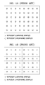
- FIGS. 1B and 1C illustrate chrominance sampling methods with a 4:2:2 format and a 4:2:0 format, respectively, in YCbCr that is generally used.
- FIG. 1A shows a 4:4:4 format that is a state before sampling.
- FIG. 1BA shows a 4:2:2 format and it can be seen that the chrominance component is reduced by half compared to the luminance component. At this time, it can be seen that two chrominance samples adjacent in the width direction are combined into one. The reason for combining samples in the width direction is that the redundancy in the width direction is generally greater than that in the length direction, and is also to easily support display in interlaced scanning.
- FIG. 1C 4 samples adjacent in the width and length directions are combined into one such that the chrominance component is reduced to one fourth of the luminance component.
- the chrominance component is reduced to one fourth of the luminance component.
- filtering is performed considering values of surrounding pixels together.
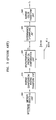
- FIG. 2 is a block diagram showing a general image encoding process.
- the color of an original image (In) is transformed by changing the color representation format through the color transform unit 200.
- Chrominance downsampling is performed in a chrominance downsampling unit 210, and then encoding process is performed through a spatiotemporal prediction unit 220, a transform/quantization unit 230, an entropy encoding unit 240, an inverse quantization/inverse transform unit 250, and a spatiotemporal prediction compensation unit 260.
- FIG. 3 is a block diagram showing a general image decoding process.
- a bitstream is entropy decoded in an entropy decoding unit 300, and inverse quantization and inverse transform are performed in an inverse quantization/inverse transform unit 310, and by doing so, decoding is performed.
- the decoded image (F'n) undergoes chrominance upsampling and inverse color transform in a chrominance upsampling unit 330 and an inverse color transform unit 340 such that a restored image (I'n) is generated.
- the present invention provides a residue image down- and/or up-sampling apparatus and method by which a residue image generated through prediction encoding is sampled.
- the present invention also provides an image encoding and/or decoding apparatus and method using residue sampling, in which a residue image generated through prediction encoding during data is encoded is sampled.
- the present invention also provides a down- and/or up-sampling method of an RGB color image.
- a residue image downsampling method including: generating a residue corresponding to the difference between an original image and a predicted image, for each image component of the original image formed with at least two or more image components; and downsampling the residue for each image component at a predetermined ratio.
- the generating of the residue may include: in case of intra mode, obtaining a predicted image for each component of the original image by estimating a prediction direction from a pixel spatially close to the pixel block of a current frame of each image component, and in case of inter mode, obtaining a predicted image by estimating a motion in units of blocks with a predetermined size between a current frame of each image component and the previous frame; and obtaining a residue by subtracting the predicted image from the original image.
- the original image may be one of an R-G-B format image, a Y-Cb-Cr format image, and an X-Y-Z format image.
- the method may further include before the generating of the residue: performing color transform of the original image formed with at least two or more image components, wherein in the generating of the residue, for each component of the color transformed image, a residue corresponding to the difference between the color transformed image and a predicted image is generated.
- the method may further include: transforming the generated residue by using the relation between residues of respective image components, wherein in the downsampling of the residue, the transformed residue for each image component is downsampled at a predetermined ratio.
- a residue image downsampling apparatus including: a spatiotemporal prediction unit generating a residue corresponding to the difference between an original image and a predicted image, for each image component of the original image formed with at least two or more image components; and a downsampling unit downsampling the residue for each image component at a predetermined ratio.
- the spatiotemporal prediction unit may obtain a predicted image for each component of the original image by estimating a prediction direction from a pixel spatially close to the pixel block of a current frame of each image component, and in case of inter mode, may obtain a predicted image by estimating a motion in units of blocks with a predetermined size between a current frame of each image component and the previous frame, and generate a residue by obtaining the difference of the predicted image from the original image.
- the original image may be one of an R-G-B format image, a Y-Cb-Cr format image, and an X-Y-Z format image.
- the apparatus may further include: a color transform unit performing color transform of the original image expressed in a predetermined color image format into another format color image expression, wherein for each component of the color transformed image, the spatiotemporal prediction unit generates a residue corresponding to the difference between the color transformed image and a predicted image.
- the apparatus may further include: a residue transform unit transforming the residue by using the relation between residues of respective image components, in relation to the residue generated in the spatiotemporal prediction unit, wherein the downsampling unit downsamples the transformed residue of each image component at a predetermined ratio.
- a residue image upsampling method including: when in an original image formed with at least two or more image components, the difference between the original image and a predicted image is referred to as a residue, upsampling downsampled data of the residue data; and restoring the original image by adding the predicted image to the upsampled residue of each component.
- the upsampling may be performed in units of image data blocks with a predetermined size and for pixels on the left-hand side boundary and top boundary of a current block, upsampling may be performed by using pixel values of the current block.
- the original image may be one of an R-G-B format image, a Y-Cb-Cr format image, and an X-Y-Z format image.
- the predicted image for each component of the original image may be obtained by estimating a prediction direction from a pixel spatially close to the pixel block of a current frame of each image component, and in case of inter mode, the predicted image may be obtained by estimating a motion in units of blocks with a predetermined size between a current frame of each image component and the previous frame.
- the upsampling of data may further include: performing inverse residue transforming of the upsampled data; and in the restoring of the original image, the original image is restored by adding the predicted image to the inverse residue transformed residue of each component.
- the restoring of the original image may further include: if the original image is transformed into a predetermined color image expression format when it is downsampled, inverse transforming the original image into a predetermined different color image expression format.
- a residue image upsampling apparatus including: an upsampling unit upsampling downsampled data of residue data when in an original image formed with at least two or more image components, the difference between the original image and a predicted image is referred to as a residue; and a spatiotemporal prediction compensation unit restoring the original image by adding the predicted image to the upsampled residue of each component.
- the original image may be one of an R-G-B format image, a Y-Cb-Cr format image, and an X-Y-Z format image.
- the spatiotemporal prediction compensation unit may obtain a predicted image for each component of the original image by estimating a prediction direction from a pixel spatially close to the pixel block of a current frame of each image component, and in case of inter mode, may obtain a predicted image by estimating a motion in units of blocks with a predetermined size between a current frame of each image component and the previous frame, and restore an original image by adding the predicted image to the upsampled residue of each component.
- the upsampling of the upsampling unit may be performed in units of image data blocks with a predetermined size and for pixels on the left-hand side boundary and top boundary of a current block, upsampling may be performed by using pixel values of the current block.
- the upsampling unit may further include: an inverse residue transform unit performing inverse residue transforming of the upsampled data; and the spatiotemporal prediction compensation unit restores the original image by adding the predicted image to the inverse residue transformed residue of each component.
- the spatiotemporal prediction compensation unit may further include: an inverse color transform unit performing inverse color transform of the original image into a predetermined different color image expression format.
- an image encoding method using residue sampling including: generating a residue corresponding to the difference between an original image and a predicted image, for each image component of the original image formed with at least two or more image components; downsampling the residue for each image component at a predetermined ratio; and generating a bitstream by encoding the downsampled data.
- the generating of the residue may include: in case of intra mode, obtaining a predicted image for each component of the original image by estimating a prediction direction from a pixel spatially close to the pixel block of a current frame of each image component, and obtaining a spatial residue by subtracting the predicted image from the original image; and in case of inter mode, obtaining a predicted image for each component of the original image by estimating a motion in units of blocks with a predetermined size between a current frame of each image component and the previous frame, and obtaining a temporal residue by subtracting the predicted image from the original image.
- the original image may be one of an R-G-B format image, a Y-Cb-Cr format image, and an X-Y-Z format image.
- the method may further include before the generating of the residue: performing color transform of the original image formed with at least two or more image components, into a different color image expression format, wherein in the generating of the residue, for each component of the color transformed image, a residue corresponding to the difference between the color transformed image and a predicted image is generated.
- the method may further include: transforming the generated residue by using the relation between residues of respective image components, wherein in the downsampling of the residue, the transformed residue for each image component is downsampled at a predetermined ratio.
- the generating of the bitstream may include: transforming and quantizing the downsampled data; and generating a bitstream by entropy encoding the quantized data.
- the generation of the predicted image may include: performing inverse quantization and inverse transform the signal generated through the transform and quantization; upsampling the inverse transformed data; and generating a restored image by performing prediction compensation of the upsampled data.
- an image encoding method using residue sampling including: in an original image formed with at least two or more image components, for each of the image components, generating a residue corresponding to the difference of an original image and a predicted image in units with a predetermined size; determining whether or not to perform sampling of the generated residue, by using predetermined information indicating whether or not to perform sampling; if it is determined to perform sampling, downsampling the residue image at a predetermined ratio; and if sampling is performed, encoding the downsampled data, and if sampling is not performed, encoding residue data to generate a bitstream.
- Information indicating whether or not to perform sampling of a residue may be selectively set with respect to the size unit of image data.
- the information indicating whether or not to perform sampling of a residue may be set in units of sequences of an image desired to be encoded and in units of macroblocks in the sequence.
- an image encoding apparatus using residue sampling including: a residue generation unit generating a residue corresponding to the difference between an original image and a predicted image, for each image component of the original image formed with at least two or more image components; a downsampling unit downsampling the residue for each image component at a predetermined ratio; and an encoding unit generating a bitstream by encoding the downsampled data.
- the residue generation unit may include: a spatial residue generation unit obtaining a predicted image for each component of the original image in case of intra mode, by estimating a prediction direction from a pixel spatially close to the pixel block of a current frame of each image component, and obtaining a spatial residue by subtracting the predicted image from the original image; and a temporal residue generation unit obtaining a predicted image for each component of the original image in case of inter mode, by estimating a motion in units of blocks with a predetermined size between a current frame of each image component and the previous frame, and obtaining a temporal residue by subtracting the predicted image from the original image.
- the original image may be one of an R-G-B format image, a Y-Cb-Cr format image, and an X-Y-Z format image.
- the apparatus may further include: a color transform unit performing color transform of the original image formed with at least two or more image components, into a different color image expression format, wherein for each component of the color transformed image, the residue generation unit generates a residue corresponding to the difference between the color transformed image and a predicted image.
- a color transform unit performing color transform of the original image formed with at least two or more image components, into a different color image expression format, wherein for each component of the color transformed image, the residue generation unit generates a residue corresponding to the difference between the color transformed image and a predicted image.
- the apparatus may further include: a residue transform unit transforming the residue generated in the residue generation unit, by using the relation between residues of respective image components, wherein the downsampling unit downsamples the transformed residue for each image component at a predetermined ratio.
- the encoding unit may include: a transform/quantization unit transforming and quantizing the downsampled data; and an entropy encoding unit generating a bitstream by entropy encoding the quantized data.
- the apparatus may further include: a predicted image generation unit generating a predicted image input to the residue generation unit, wherein the prediction image generation unit may include: an inverse quantization/inverse transform unit performing inverse quantization and inverse transform of a signal generated through the transform and quantization; an upsampling unit upsampling the inverse transformed data; and a spatiotemporal prediction compensation unit generating a restored image by performing prediction compensation of the upsampled data.
- the prediction image generation unit may include: an inverse quantization/inverse transform unit performing inverse quantization and inverse transform of a signal generated through the transform and quantization; an upsampling unit upsampling the inverse transformed data; and a spatiotemporal prediction compensation unit generating a restored image by performing prediction compensation of the upsampled data.
- an image encoding apparatus using residue sampling including: a spatiotemporal prediction unit generating a residue for each of the image components in units with a predetermined size from the original image formed with at least two or more image components, the residue corresponding to the difference of an original image and a predicted image; a sampling determination unit determining whether or not to perform sampling, with respect to the predetermined size unit of image data; a downsampling unit downsampling the generated residue image at a predetermined ratio if the sampling determination unit determines to perform sampling; and an encoding unit encoding the downsampled data, if sampling is performed, and if sampling is not performed, encoding residue data to generate a bitstream.
- an image decoding method using residue sampling including: when in an original image formed with at least two or more image components, the difference between the original image and a predicted image is referred to as a residue, generating downsampled data of residue data by performing at least entropy decoding from a bitstream; upsampling downsampled data of the residue data; and restoring the original image by adding the predicted image to the upsampled residue of each component.
- the generating of downsampled data of residue data may include: when in the original image formed with at least two or more image components, the difference between the original image and a predicted image is referred to as a residue, performing entropy decoding from a bitstream; and generating downsampled data of the residue data, by performing inverse quantization and inverse transform of the entropy encoded data.
- the original image may be one of an R-G-B format image, a Y-Cb-Cr format image, and an X-Y-Z format image.
- the predicted image for each component of the original image may be obtained by estimating a prediction direction from a pixel spatially close to the pixel block of a current frame of each image component, and in case of inter mode, the predicted image may be obtained by estimating a motion in units of blocks with a predetermined size between a current frame of each image component and the previous frame.
- the upsampling of data may be performed in units of image data blocks with a predetermined size and for pixels on the left-hand side boundary and top boundary of a current block, the upsampling may be performed by using pixel values of the current block.
- the upsampling of data may further include: performing inverse residue transforming of the upsampled data; and in the restoring of the original image, the original image is restored by adding the predicted image to the inverse residue transformed residue of each component.
- the restoring of the original image may further include: if the original image is transformed into a predetermined color image expression format when it is downsampled, inverse transforming the original image into a predetermined different color image expression format.
- an image decoding method using residue sampling including: restoring data by performing at least entropy decoding from a bitstream when in an original image formed with at least two or more image components, the difference between the original image and a predicted image is referred to as a residue; determining whether or not the restored data is downsampled data; if the data is downsampled residue data, performing upsampling; and restoring the original image by adding a predicted image to the restored data if it is determined that the data is not downsampled data, and by adding the predicted image to the upsampled residue of each component if it is determined that the data is downsampled data.
- the restoring the original image may include: if it is interpreted that the data is not downsampled data, performing inverse residue transform of the data restored in the data restoration unit, and if it is interpreted that the data is downsampled data, performing inverse residue transform of the upsampled data; and restoring the original image by adding the predicted image to the inverse residue transformed data.
- an image decoding apparatus using residue sampling including: a data restoration unit generating downsampled data of residue data when in an original image formed with at least two or more image components, the difference between the original image and a predicted image is referred to as a residue; an upsampling unit upsampling downsampled data of the residue data; and a spatiotemporal prediction compensation unit restoring the original image by adding the predicted image to the upsampled residue of each component.
- the data restoration unit may include: an entropy decoding unit performing entropy decoding from a bitstream when in an original image formed with at least two or more image components, the difference between the original image and a predicted image is referred to as a residue; and an inverse quantization/inverse transform unit generating downsampled data of residue data, by performing inverse quantization and inverse transform of the entropy decoded data.
- the original image may be one of an R-G-B format image, a Y-Cb-Cr format image, and an X-Y-Z format image.
- the predicted image for each component of the original image may be obtained by estimating a prediction direction from a pixel spatially close to the pixel block of a current frame of each image component, and in case of inter mode, the predicted image may be obtained by estimating a motion in units of blocks with a predetermined size between a current frame of each image component and the previous frame.
- the upsampling of the upsampling unit may be performed in units of image data blocks with a predetermined size and for pixels on the left-hand side boundary and top boundary of a current block, upsampling may be performed by using pixel values of the current block.
- the apparatus may further including: an inverse residue transform unit performing inverse residue transform of the upsampled data, wherein the spatiotemporal prediction compensation unit restores the original image by adding the predicted image to the inverse residue transformed residue of each component.
- the apparatus may further include: an inverse color transform unit performing inverse color transform of the image restored in the spatiotemporal prediction compensation unit into a predetermined different color image expression format if the original image is transformed into a predetermined color image expression format when it is downsampled.
- an image decoding apparatus using residue sampling including: a data restoration unit performing at least entropy decoding from a bitstream when in an original image formed with at least two or more image components, the difference between the original image and a predicted image is referred to as a residue; a sampling information interpretation unit interpreting whether or not data restored in the data restoration unit is downsampled data; an upsampling unit performing upsampling of downsampled data of the residue data; and a spatiotemporal prediction compensation unit restoring the original image by adding a predicted image to the data restored in the data restoration unit if the sampling information interpretation unit interprets that the data is not downsampled data, and by adding the predicted image to the upsampled residue of each component if the sampling information interpretation unit interprets that the data is downsampled data.
- the apparatus may further include: an inverse residue transform unit performing inverse residue transform of the data restored in the data restoration unit, if the sampling information interpretation unit interprets that the data is not downsampled data, and if the sampling information interpretation interprets that the data is downsampled data, performing inverse residue transform of the upsampled data, wherein the spatiotemporal prediction compensation unit restores the original image by adding the predicted image to the inverse residue transformed data.
- a downsampling method of an RGB color image including: examining visual importance of each component of an RGB color image; and downsampling each component of the RGB color image at a predetermined ratio on the basis of the visual importance.
- the downsampling ratio of each component of the RGB color image may be 4:2:2 or 2:2:1.
- an upsampling method of an RGB color image including: dividing a downsampled RGB color image into R, G, and B components; and upsampling each component of the downsampled RGB color image at a ratio corresponding to the downsampling.
- a computer readable medium having embodied thereon a computer program for any of the methods.
- spatiotemporal prediction encoding is performed, the data amount of an image desired to encode is greatly reduced. Accordingly, in order to reduce information loss by sampling, when a color transformed image is encoded, sampling is not directly performed, but spatiotemporal prediction encoding is first performed to obtain a residue image.
- An image in which the chrominance component is not sampled as shown in FIG. 1A can be a color transformed image that is an image input in this case. At this time, only the chrominance component can be sampled as in the conventional method, or both the luminance component and the chrominance component can be sampled.
- the loss will become great and therefore, only the chrominance component is sampled and the luminance component is not sampled.
- the loss can be reduced.
- the sampling ratios of the luminance component and the chrominance component can be differentiated.
- the present invention since the luminance component and the chrominance component can be effectively sampled, the present invention can be applied even to the images in which chrominance components are already sampled as in FIGS. 1B and 1C .
- the chrominance component since the chrominance component is already sampled, only the residue of the luminance component can be sampled or the chrominance component can be further sampled, or both the luminance and chrominance components can be sampled together.
- sampling is performed with a residue image obtained through a spatiotemporal prediction process.
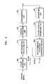
- FIG. 4 is a block diagram of a preferred embodiment of the structure of a downsampling apparatus of a residue image according to the present invention.
- the downsampling apparatus of a residue image includes a color transform unit 400, a spatiotemporal prediction unit 410, a residue transform unit 420, a downsampling unit 430, an upsampling unit 440, an inverse residue transform unit 450, and a spatiotemporal prediction compensation unit 460.
- the color transform unit 400 transforms an original image expressed in a predetermined color image format into another format color image expression.
- the RGB image can be color transformed into a YCbCr image.
- a residue can be generated after color transform through the color transform unit 400, or a residue can be generated directly from the original image without going through the color transform unit 400.
- the residue generation is performed in units with a predetermined size.
- the spatiotemporal prediction unit 410 generates a residue image for each image component of an original image when color transform is not performed, or of a color transformed image when color transform is performed, in which the residue image is obtained by the difference between a predicted image and the color transformed image or the original image.
- the method for obtaining the predicted image is as follows. In case of intra mode, a predicted image for each component of the original image is obtained by estimating a prediction direction from a pixel spatially close to the pixel block of a current frame of each image component. In case of inter mode, a predicted image is obtained by estimating a motion in units of blocks with a predetermined size between a current frame of each image component and the previous frame.
- each of R, G, and B indicates the image of a corresponding component of the color image
- Rp, Gp, and Bp indicate the predicted image of R, G, and B, respectively.
- the predicted image is used to remove redundant information in each color component, and the signal remaining after the redundant information is removed is referred to as a residue.
- the residue transform unit 420 performs residue transform of the residue generated by the spatiotemporal prediction unit 410 according to a predetermined residue transform formula. When necessary, the residue transform unit 420 can be omitted. That is, the residue generated by the spatiotemporal prediction unit 410 can be directly downsampled by the downsampling unit 430.
- ⁇ 2 X 1 , ⁇ 2 X 2 , and ⁇ 2 X 3 are residue transformed signals.
- ⁇ 2 R, ⁇ 2 G, and ⁇ 2 B are residue transformed signals.
- ⁇ 2 X 1 , ⁇ 2 X 2 , and ⁇ 2 X 3 are residue transformed signals.
- each of the components corresponding to Co and Cg, respectively, among ⁇ R, ⁇ G, and ⁇ B components, should be multiplied by 4 and then used.
- Equation 7 is obtained by generalizing YCoCg-R.
- This transform can also be applied to a residue transform formula in the same manner.
- each of the components corresponding to Co and Cg, respectively, among ⁇ R, ⁇ G, and ⁇ B components, is multiplied by 2 such that lossless transform is enabled without a rounding error.
- the downsampling unit 430 downsamples the residue transformed signal if the sampling apparatus has the residue transform unit 420, or downsamples residue data generated in the spatiotemporal prediction unit 410 if the sampling apparatus does not have the residue transform unit 420.
- the sampling ratio for each component may vary. For example, in case of an image formed with a luminance component and a chrominance component, the luminance component may not be sampled with sampling only the chrominance component, or the sampling ratio of the luminance component can be made to be higher than that of the chrominance component.
- the upsampling unit 440, the inverse residue transform unit 450 and the spatiotemporal prediction compensation unit 460 are used to generate a predicted image.
- the upsampling unit 440 upsamples a signal downsampled through the downsampling unit 420, and the inverse residue transform unit 450 performs inverse residue transform of the upsampled data.
- the spatiotemporal prediction compensation unit 460 generates a restored image (F'n), by performing spatiotemporal prediction compensation of the residue transformed data.
- the inverse residue transform unit 450 performs inverse residue transform of only the data residue transformed through the residue transform unit 420.
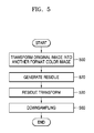
- FIG. 5 is a flowchart of the operations performed by a preferred embodiment of a downsampling method of a residue image according to the present invention. Referring to FIGS. 4 and 5 , the downsampling method of a residue image and the operations of the downsampling apparatus of a residue image according to the present invention will now be explained.
- an original image is input to the color transform unit 400, the image is transformed into a different format color image in operation 500.
- the original image is a color image of an RGB signal, it can be transformed into a luminance signal and a chrominance signal in a YCbCr format.
- the color transformed signal is input to the spatiotemporal prediction unit 410 such that for each image component, a residue image obtained by the difference between a predicted image and the color transformed image or the original image is generated in operation 520.
- a residue can be generated after color transform is performed by the color transform unit 400, or a residue can be generated directly from the original image without going through the color transform unit 400.
- the predicted image is generated with the downsampled signal going through the upsampling unit 440, the inverse residue transform unit 450, and the spatiotemporal prediction compensation unit 460 sequentially. That is, the downsampled signal is upsampled by the upsampling unit 440, inverse residue transformed by the inverse residue transform unit 450, and then spatiotemporal prediction compensated by the spatiotemporal prediction compensation unit 460 such that the restored image (F'n) is generated.
- the predicted image is obtained as follows. In case of intra mode, the predicted image for each component of the original image is obtained by estimating a prediction direction from a pixel spatially close to the pixel block of a current frame of each image component. In case of inter mode, the predicted image is obtained by estimating a motion in units of blocks with a predetermined size between a current frame of each image component and the previous frame.
- the inverse residue transform unit 450 performs inverse residue transform of only the data residue transformed through the residue transform unit 420.
- the generated residue image is input to the residue transform unit 420 and according to a predetermined residue transform formula, residue transformed in operation 530. Since the explanation of the residue transform is the same as described in the residue transform unit 420, it will be omitted here.
- the residue transformed data is input to the downsampling unit 410 and downsampled in operation 560. Since the residue transform unit 420 can be omitted when necessary, the residue generated by the spatiotemporal prediction unit 410 can be directly downsampled by the downsampling unit 430.
- FIG.6 is a block diagram of a preferred embodiment of the structure of an upsampling apparatus of a residue image according to the present invention.
- the upsampling apparatus includes an upsampling unit 600, an inverse residue transform unit 620, a spatiotemporal prediction compensation unit 640, and an inverse color transform unit 660.
- the upsampling unit 600 upsamples the downsampled residue data.
- the inverse residue transform unit 620 performs inverse residue transform of the upsampled data.
- the inverse residue transform is the inverse process of the residue transform and uses the inverse transform formula of the residue transform formula, which is used when the residue is transformed. Accordingly, inverse residue transform is performed by using equation 9 as the inverse transform formula if the transform formula equation 2 is used for residue transform, equation 10 as the inverse transform formula if the transform formula equation 4 is used, and equation 11 as the inverse transform formula if the transform formula equation 7 is used.
- equation 9 as the inverse transform formula if the transform formula equation 2 is used for residue transform
- equation 10 as the inverse transform formula if the transform formula equation 4 is used
- equation 11 as the inverse transform formula if the transform formula equation 7 is used.
- ⁇ 2 X 1 , ⁇ 2 X 2 , and ⁇ 2 X 3 are residue transformed signals.
- ⁇ ⁇ X 1 ⁇ ⁇ X 2 ⁇ ⁇ X 3 1 1 - 1 1 0 1 1 - 1 - 1 ⁇ ⁇ 2 ⁇ X 1 ⁇ 2 ⁇ X 2 ⁇ 2 ⁇ X 3
- ⁇ 2 X 1 , ⁇ 2 X 2 , and ⁇ 2 X 3 are residue transformed signals.
- ⁇ 2 X 1 , ⁇ 2 X 2 , and ⁇ 2 X 3 are residue transformed signals.
- the spatiotemporal prediction compensation unit 640 restores the original image by adding the predicted image to the residue for each component, the residue inverse residue transformed in the inverse residue transform unit 620. If the downsampled data is not residue transformed, the upsampled data is directly input to the spatiotemporal prediction compensation unit 640 and by adding the predicted image to the residue for each component, the original image is restored.
- the original image can be, for example, any one image of an R-G-B format, a Y-Cb-Cr format, and an X-Y-Z format.
- the spatiotemporal prediction compensation unit 640 will now be explained in more detail.
- the spatiotemporal prediction compensation unit 640 obtains a predicted image for each component of the original image in case of intra mode, by estimating a prediction direction from a pixel spatially close to the pixel block of a current frame of each image component, and obtains a predicted image in case of inter mode, by estimating a motion in units of blocks with a predetermined size between a current frame of each image component and the previous frame. Then, by adding the predicted image to the upsampled residue for each component, the spatiotemporal prediction compensation unit 640 restores the original image.
- the inverse color transform unit 660 performs inverse color transform of the color transform so that the original image is restored. For example, if the original image is an RGB image and is color transformed to a YCbCr color expression format before downsampling, the inverse color transform unit 660 performs inverse color transform of the color image in the YCbCr expression format into the color image in the RGB expression format.
- FIG. 7 is a flowchart of the operations performed by a preferred embodiment of an upsampling method of a residue image according to the present invention. Referring to FIGS. 6 and 7 , the upsampling method of a residue image and the operations of the apparatus according to the present invention will now be explained.
- upsampling is performed in operation 700.
- the upsampled data is inverse residue transformed by the inverse residue transform unit 620 in operation 720. Since the explanation of the inverse residue transform is the same as described in the inverse residue transform unit 620, detailed explanation will be omitted.
- the inverse residue transformed data is input to the spatiotemporal prediction compensation unit 640 and by adding the predicted image to the reside for each component, the original image is restored in operation 740. More specifically, in case of intra mode, a predicted image for each component of the original image is obtained by estimating a prediction direction from a pixel spatially close to the pixel block of a current frame of each image component, and in case of inter mode, a predicted image is obtained by estimating a motion in units of blocks with a predetermined size between a current frame of each image component and the previous frame. Then, by adding the predicted image to the upsampled residue for each component, the original image is restored.
- the downsampled image being input to the upsampling unit 600 didn't go through a residue transform process before the image was downsampled, the downsampled image is directly input to the spatiotemporal prediction compensation unit 640 without inverse residue transform and by adding the predicted image to the residue for each component, the original image is restored. Also, if the downsampled image being input to the upsampling unit 600 has been color transformed to change the color expression format before the image was downsampled, the image restored in the spatiotemporal prediction compensation unit 640 is input to the inverse color transform unit 660 such that the image is inverse color transformed and the original image is restored in operation 760.
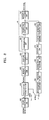
- FIG. 8 is a block diagram of a preferred embodiment of an image encoding apparatus using residue downsampling according to the present invention.
- the image encoding apparatus using residue downsampling includes: a color transform unit 800, a spatiotemporal prediction unit 810, a residue transform unit 820, a downsampling unit 830, a transform/quantization unit 840, an entropy encoding unit 850, an inverse quantization/inverse transform unit 860, an upsampling unit 870, an inverse residue transform unit 880 and a spatiotemporal prediction compensation unit 890.
- the explanations on the color transform unit 800, the spatiotemporal prediction unit 810, the residue transform unit 820, the downsampling unit 830, the upsampling unit 870, the inverse residue transform unit 880, and the spatiotemporal prediction compensation unit 890 are the same as described in the downsampling apparatus of a residue image, the explanations will be omitted.
- a sampling determination unit 825 determines whether or not to perform sampling selectively according to a predetermined size unit of image data.
- the image data size can be any of a variety of sizes, such as a sequence, a frame, a macroblock, and a 4x4 block.
- information indicating whether or not to perform sampling can be set as one of sequence parameters (residue_sampling_flag), and even in a sequence, it can be set by using a flag (mb_residue_sampling_flag) in units of macroblocks.
- the downsampling unit 830 downsamples the residue image at a predetermined ratio. Then, the encoding unit 80 generates a bitstream by encoding the downsampled data when downsampling is performed, or the residue data when sampling is not performed.
- the upsampling unit 440 of FIG. 4 upsamples downsampled data
- the upsampling unit 870 of FIG. 8 upsamples inverse quantized and inverse transformed data.
- the transform/quantization unit 840 and the entropy encoding unit 850 are also referred collectively to as an encoding unit 80.
- the transform/quantization unit 840 performs lossy compression of the data downsampled in the downsampling unit 830, through transform (for example, DCT transform) and quantization in units of blocks with a predetermined size.
- the entropy encoding unit 850 generates a bitstream by entropy encoding the data transformed and quantized in the transform/quantization unit 840.
- the inverse quantization/inverse transform unit 860 performs inverse transform and inverse quantization of the transformed and quantized data. In case of lossless encoding, the transform/quantization unit 840 is not used. In this case, the inverse quantization/inverse transform 860 is not necessary.
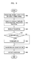
- FIG. 9 is a flowchart of the operations performed by a preferred embodiment of an image encoding method using residue downsampling according to the present invention. Referring to FIGS. 8 and 9 , the image encoding method using residue downsampling and the operation of the apparatus will now be explained.
- sampling can be performed adaptively. That is, by using predetermined information indicating whether or not to perform residue sampling, it is determined whether or not to perform sampling of the generated residue in operation 925. For example, when information indicating whether or not to perform sampling is represented by a flag, it can be indicated as two types. Information indicating whether or not to perform sampling of a sequence can be expressed as residue_sampling_flag, while information indicating whether or not to perform sampling of a macroblock forming a frame of the sequence can be expressed as mb_residue_sampling_flag.
- residue_sampling_flag is set to "0"
- no mb_residue_sampling_flag exists in a corresponding sequence and no sampling is performed in any macroblock in the seqence.
- residue_sampling_flag is set to "1”
- mb_residue_sampling_flag indicating whether or not to perform sampling on a macroblock in a sequence exists. If residue_sampling_flag is set to "1" and mb_residue_sampling_flag in a macroblock is set to "1”, it is determined to perform downsampling in the corresponding macroblock. If mb_residue_sampling_flag is set to "0", it is determined not to perform downsampling in the corresponding macroblock.
- the residue image is downsampled at a predetermined ratio in operation 930. If sampling is performed, the downsampled data is encoded, and if sampling is not performed, residue data is encoded to generate a bitstream in operations 940 and 950.
- the downsampled data is input to the transform/quantization unit 840 and transformed and quantized in operation 940, and then is input to the entropy encoding unit 850 and entropy encoded in operation 950.
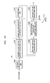
- FIG. 10 is a block diagram of a preferred embodiment of an image decoding apparatus using residue upsampling according to the present invention.
- the image decoding apparatus using residue upsampling includes: a data restoration unit 10, a sampling information interpretation unit 1015, an upsampling unit 1020, an inverse residue transform unit 1030, a spatiotemporal prediction compensation unit 1040, and an inverse color transform unit 1050.
- the data restoration unit 10 generates restored data by performing at least entropy decoding of a bitstream. Accordingly, when necessary, the data restoration unit 10 includes an entropy decoding unit 1000 and an inverse quantization/inverse transform unit 1010.
- the entropy decoding unit 1000 performs entropy decoding of the bitstream.
- the inverse quantization/inverse transform unit 1010 performs inverse quantization and inverse transform of the entropy decoded data. In case of lossless encoding, the inverse quantization/inverse transform unit 1010 is not needed.
- the image decoding apparatus using residue upsampling according to the present invention uses the upsampling apparatus of a residue image according to the present invention. Accordingly, since the structures of the upsampling unit 1020, the inverse residue transform unit 1030, the spatiotemporal prediction compensation unit 1040, and the inverse color transform unit 1050 are the same as those described above in the upsampling apparatus of a residue image, further explanation will be omitted here.
- sampling information interpretation unit 1015 is needed.
- the sampling information interpretation unit 1015 interprets whether the data restored in the data restoration unit 10 is downsampled data or not.
- the upsampling unit 1020 upsamples the downsampled data of the residue data. If the sampling information interpretation unit 1015 interprets that the data is not downsampled data, the spatiotemporal prediction compensation unit 1040 adds a predicted image to the data restored in the data restoration unit 10, and if the sampling information interpretation unit 1015 interprets that the data is downsampled data, adds the predicted image to the upsampled residue of each component so that the original image is restored.
- the inverse residue transform unit 1030 When inverse residue transform is needed, if the sampling information interpretation unit 1015 interprets that the data is not downsampled data, the inverse residue transform unit 1030 performs inverse residue transform of the data restored in the data restoration unit 10, and if the sampling information interpretation unit 1015 interprets that the data is downsampled data, performs inverse residue transform of the upsampled data.
- the spatiotemporal prediction compensation unit 1040 restores the original image by adding a predicted image to the inverse residue transformed data.
- FIG. 11 is a flowchart of the operations performed by a preferred embodiment of an image decoding method using residue upsampling according to the present invention.
- bitstream of image data is entropy decoded in operation 1100. If the bitstream is lossy encoded data, the entropy decoded data is input to the inverse quantization/inverse transform unit 1010 and through inverse quantization and inverse transform, data is restored in operation 1110. If the bitstream is lossless encoded data, it does not go through a transform and quantization process when data is encoded.
- the operations 1120 through 1150 shown in FIG. 11 are the same as in the upsampling method of a residue image described above.
- image data restored to the downsampled data is upsampled by the upsampling unit 1020 in operation 1120, and inverse residue transformed by the inverse residue transform unit 1030 in operation 1130. Then, the image is restored by the spatiotemporal prediction compensation unit 1040 in operation 1140 and inverse color transformed by the inverse color transform unit 1050 in operation 1150.
- sampling information interpretation is needed.
- sampling information interpretation unit 1015 it is determined whether or not the data restored in the data restoration unit 10 is downsampled data in operation 1115.
- sampling information interpretation unit 1015 interprets that the data is downsampled data
- the downsampled data of the residue data is upsampled in operation 1120.
- sampling information interpretation unit 1015 interprets that the data is not downsampled data, a predicted image is added to the data restored in the data restoration unit 10, and if the sampling information interpretation unit 1015 interprets that the data is downsampled data, the predicted image is added to the upsampled residue for each component in order to restore the original image in operation 1140.
- the sampling information interpretation unit 1015 interprets that the data is not downsampled data, the data restored in the data restoration unit 10 is inverse residue transformed, and if the sampling information interpretation unit 1015 interprets that the data is downsampled data, the upsampled data is inverse residue transformed in operation 1130.
- the original image is restored by adding a predicted image to the inverse residue transformed data through the spatiotemporal prediction compensation unit 1040 in operation 1150.
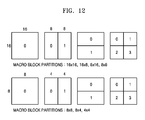
- FIG. 12 illustrates that in the sampling apparatus and method of a residue image and the image encoding apparatus and method using the sampling apparatus and method according to the present invention described above, when prediction encoding is performed by the spatiotemporal prediction unit 410 and 810, in case of inter mode, temporal prediction is performed by dividing a macroblock into blocks with a predetermined size.
- a macroblock desired to be currently encoded is divided into blocks of a predetermined size and prediction is performed.
- the method is the one that is used in ISO/IEC 14496-10 and ITU-T Rec. H.264 standards technologies.
- a macroblock with a size of 16x16 pixels is divided into a variety of sizes, including 16x16, 16x8, 8x16 and 8x8, and the motion vector of each divided block is obtained to predict an image value temporally.
- a block with an 8x8 size is again divided into 8x8, 8x4, 4x8, and 4x4 sizes such that file motions can be accurately sensed.
- FIG. 13 illustrates a method for spatial prediction in case of intra mode when prediction encoding is performed.
- FIG. 13A shows locations of pixels of a current block and locations of adjacent pixels to be used for prediction. The method is the one that is used in ISO/IEC 14496-10 and ITU-T Rec. H.264 standards technologies.
- FIG. 13A in order to predict block data with a 4x4 size (pa, pb, ..., pq), data previously encoded and restored and spatially adjacent (P0, P1, ..., P12) are used.
- FIG. 13B illustrates 9 types of prediction directions 0 through 8 to predict a current block through projection from spatially adjacent pixels.
- This spatial and/or temporal prediction method is explained by using the conventional standard technology as an example, and other methods can also be used.
- residue transform can be performed.
- the reason for performing the transform is to remove redundancy present between respective components.
- an image that does not go through color transform for example, in case of an RGB image
- the encoding efficiency is lowered because there is information redundant between respective components. Accordingly, in order to remove redundant information between respective components, residue transform is performed.
- an input image is a color transformed image or a residue transformed image
- the luminance component and the chrominance component can be separated as shown in FIG. 1B or 1C , and only the chrominance component can be sampled in a 1/2 or 1/4 ratio.
- a method for sampling there is a method using an average value by using adjacent pixels, and also a variety of filtering methods can be applied.
- an input image is not color transformed and not residue transformed, also through spatiotemporal prediction, a residue image can be generated and by sampling the residue image, the encoding efficiency can be enhanced. At this time, by considering visual importance of each component, a different sampling ratio may be applied.
- downsampling of an RGB color image can be performed. That is, visual importance of each component of the RGB color image is checked first, and on the basis of the visual importance, each component of the RGB color image can be downsampled at a different ratio.
- FIG. 14A if it is assumed that G, R, and B in an RGB image are in order of decreasing visual influence, from residues of each component, sampling can be performed by using 2 residue samples of R components and 1 residue sample of B component for each 4 residue samples of G components. Also, as shown in FIG. 14B , by using 1 B component sample for each two G component samples and R component samples, sampling can be performed.
- upsampling of the downsampled RGB color image can be performed. For this, first, the downsampled RGB color image is divided into R, G, and B components. Then, each component of the downsampled RGB color image is upsampled in a ratio corresponding to the downsampling.
- FIG. 15 illustrates an upsampling process for upsampling image data using a current block.
- Upsampling of image data can be performed in units of blocks with a predetermined size. Downsampled data as shown in FIG. 15A is upsampled through bi-linear interpolation as shown in FIG. 15B . However, for pixels on the left-hand side boundary and on the top boundary of a current block, the bi-linear interpolation should be performed by using adjacent block pixels. In FIG. 15C , however, adjacent block pixels are not used, and pixels of the current block are used to obtain values of pixels on the left-hand side boundary and top boundary of the current block.
- interpolation of pixels on the left-hand boundary of the current block can be performed by using right-hand side pixel values adjacent to the left-hand side pixels of the current block
- interpolation of pixels on the top boundary of the current block can be performed by using values of pixels adjacent to and below the top boundary pixels of the current block.
- the present invention can also be embodied as computer readable codes on a computer readable recording medium.
- the computer readable recording medium is any data storage device that can store data which can be thereafter read by a computer system. Examples of the computer readable recording medium include read-only memory (ROM), random-access memory (RAM), CD-ROMs, magnetic tapes, floppy disks, and optical data storage devices.
- a residue image is obtained by performing spatiotemporal prediction encoding first, and by sampling this residue image, loss of information occurring in the sampling process can be reduced.
- sampling is performed with a residue image obtained through a spatiotemporal prediction process, even when an original image that is not color transformed is directly encoded, sampling can be performed effectively. Also, the methods and apparatuses have an advantage that in addition to colors, sampling of any components can be performed effectively.
Landscapes
- Engineering & Computer Science (AREA)
- Multimedia (AREA)
- Signal Processing (AREA)
- Compression Or Coding Systems Of Tv Signals (AREA)
- Color Television Systems (AREA)
- Compression, Expansion, Code Conversion, And Decoders (AREA)
Applications Claiming Priority (4)
| Application Number | Priority Date | Filing Date | Title |
|---|---|---|---|
| KR20030098237 | 2003-12-27 | ||
| US55177804P | 2004-03-11 | 2004-03-11 | |
| KR1020040107158A KR100754388B1 (ko) | 2003-12-27 | 2004-12-16 | 레지듀 영상 다운/업 샘플링 방법 및 장치와 그를 이용한영상 부호화/복호화 방법 및 장치 |
| EP20040258101 EP1551184A3 (fr) | 2003-12-27 | 2004-12-23 | Procédé pour le sous-échantillonage et le codage d'une image résiduelle |
Related Parent Applications (1)
| Application Number | Title | Priority Date | Filing Date |
|---|---|---|---|
| EP04258101.7 Division | 2004-12-23 |
Publications (2)
| Publication Number | Publication Date |
|---|---|
| EP2224724A2 true EP2224724A2 (fr) | 2010-09-01 |
| EP2224724A3 EP2224724A3 (fr) | 2012-04-11 |
Family
ID=34577490
Family Applications (2)
| Application Number | Title | Priority Date | Filing Date |
|---|---|---|---|
| EP20040258101 Ceased EP1551184A3 (fr) | 2003-12-27 | 2004-12-23 | Procédé pour le sous-échantillonage et le codage d'une image résiduelle |
| EP20100165464 Withdrawn EP2224724A3 (fr) | 2003-12-27 | 2004-12-23 | Procédé de codage et de décodage utilisant un échantillonnage du résidue |
Family Applications Before (1)
| Application Number | Title | Priority Date | Filing Date |
|---|---|---|---|
| EP20040258101 Ceased EP1551184A3 (fr) | 2003-12-27 | 2004-12-23 | Procédé pour le sous-échantillonage et le codage d'une image résiduelle |
Country Status (2)
| Country | Link |
|---|---|
| EP (2) | EP1551184A3 (fr) |
| JP (1) | JP4991103B2 (fr) |
Cited By (1)
| Publication number | Priority date | Publication date | Assignee | Title |
|---|---|---|---|---|
| WO2012092732A1 (fr) * | 2011-01-07 | 2012-07-12 | 深圳市融创天下科技股份有限公司 | Procédé, dispositif et système de codage et de décodage de vidéo dans l'espace rouge vert bleu (rgb) |
Families Citing this family (7)
| Publication number | Priority date | Publication date | Assignee | Title |
|---|---|---|---|---|
| CN1859576A (zh) | 2005-10-11 | 2006-11-08 | 华为技术有限公司 | 对空间分层编码视频图象的上采样方法及其系统 |
| CA2665182A1 (fr) | 2006-10-10 | 2008-04-17 | Nippon Telegraph And Telephone Corporation | Procedes de codage et de decodage video, leur dispositif, leur programme, et le support de stockage contenant le programme |
| KR101370289B1 (ko) * | 2007-02-14 | 2014-03-06 | 삼성전자주식회사 | 레지듀얼 리사이징을 이용한 영상의 부호화, 복호화 방법및 장치 |
| RU2011104707A (ru) * | 2008-07-10 | 2012-08-20 | Мицубиси Электрик Корпорейшн (Jp) | Устройство кодирования изображений, устройство декодирования изображений, способ кодирования изображений и способ декодирования изображений |
| JP5375372B2 (ja) * | 2009-07-01 | 2013-12-25 | ヤマハ株式会社 | 圧縮符号化装置、および復号装置 |
| CA3000998C (fr) | 2011-01-12 | 2018-10-30 | Mitsubishi Electric Corporation | Dispositif de codage d'image, dispositif de decodage d'image, procede decodage d'image et procede de decodage d'image |
| CN117241032A (zh) * | 2017-03-12 | 2023-12-15 | 上海天荷电子信息有限公司 | 采用多种采样格式的图像及其序列、视频压缩方法和装置 |
Family Cites Families (5)
| Publication number | Priority date | Publication date | Assignee | Title |
|---|---|---|---|---|
| US5901242A (en) * | 1996-07-03 | 1999-05-04 | Sri International | Method and apparatus for decoding spatiochromatically multiplexed color images using predetermined coefficients |
| US6108383A (en) * | 1997-07-15 | 2000-08-22 | On2.Com, Inc. | Method and apparatus for compression and decompression of video images |
| EP1074091A2 (fr) * | 1998-04-20 | 2001-02-07 | Sun Microsystems, Inc. | Procede et appareil de prise en charge d'un protocole video dans un environnement reseau |
| JP2000078411A (ja) * | 1998-08-28 | 2000-03-14 | Matsushita Electric Ind Co Ltd | 可逆符号化装置及び可逆符号化方法 |
| JP2000270322A (ja) * | 1999-03-17 | 2000-09-29 | Fujitsu Ltd | 動画像符号化装置及び動画像符号化方法 |
-
2004
- 2004-12-23 EP EP20040258101 patent/EP1551184A3/fr not_active Ceased
- 2004-12-23 EP EP20100165464 patent/EP2224724A3/fr not_active Withdrawn
- 2004-12-27 JP JP2004377389A patent/JP4991103B2/ja not_active Expired - Fee Related
Non-Patent Citations (3)
| Title |
|---|
| DUGAD R ET AL: "A fast scheme for downsampling and upsampling in the DCT domain", IMAGE PROCESSING, 1999. ICIP 99. PROCEEDINGS. 1999 INTERNATIONAL CONFERENCE ON - KOBE, JAPAN 24-28 OCT. 1999, IEEE, PISCATAWAY, NJ, USA, vol. 2, 24 October 1999 (1999-10-24), pages 909 - 913, XP010369046, ISBN: 978-0-7803-5467-8, DOI: 10.1109/ICIP.1999.823030 * |
| JIE CHEN ET AL: "Design of Digital Video Coding Systems A Complete Compressed Domain Approach", 31 October 2001, MARCEL DEKKER, INC. - CRC PRESS, NEW YORK - BASEL, ISBN: 978-0-8247-0656-2, pages: 71 - 74, XP055248417 * |
| MALVAR H ET AL: "YCoCg-R: A Color Space with RGB Reversibility and Low Dynamic Range", JOINT VIDEO TEAM (JVT) OF ISO/IEC MPEG & ITU-T VCEG(ISO/IEC JTC1/SC29/WG11 AND ITU-T SG16 Q6), XX, XX, 22 July 2003 (2003-07-22), pages 1 - 5, XP002363382 * |
Cited By (1)
| Publication number | Priority date | Publication date | Assignee | Title |
|---|---|---|---|---|
| WO2012092732A1 (fr) * | 2011-01-07 | 2012-07-12 | 深圳市融创天下科技股份有限公司 | Procédé, dispositif et système de codage et de décodage de vidéo dans l'espace rouge vert bleu (rgb) |
Also Published As
| Publication number | Publication date |
|---|---|
| JP4991103B2 (ja) | 2012-08-01 |
| JP2005198292A (ja) | 2005-07-21 |
| EP1551184A3 (fr) | 2006-06-28 |
| EP1551184A2 (fr) | 2005-07-06 |
| EP2224724A3 (fr) | 2012-04-11 |
Similar Documents
| Publication | Publication Date | Title |
|---|---|---|
| US7720156B2 (en) | Residue image down/up sampling method and apparatus and image encoding/decoding method and apparatus using residue sampling | |
| US8036478B2 (en) | Color image residue transformation and/or inverse transformation method and apparatus, and color image encoding and/or decoding method and apparatus using the same | |
| JP6316487B2 (ja) | エンコーダ、デコーダ、方法、及びプログラム | |
| KR100891662B1 (ko) | 비디오 신호 디코딩 및 인코딩 방법 | |
| US8208545B2 (en) | Method and apparatus for video coding on pixel-wise prediction | |
| KR101291196B1 (ko) | 영상의 부호화, 복호화 방법 및 장치 | |
| EP2479996A1 (fr) | Codage vidéo avev une prédiction utilisant le même mode de codage pour toutes les composantes chromatiques | |
| KR100913104B1 (ko) | 영상 신호의 인코딩 및 디코딩 방법 | |
| JP5047995B2 (ja) | 映像のイントラ予測符号化、復号化方法及び装置 | |
| US8170355B2 (en) | Image encoding/decoding method and apparatus | |
| KR100891663B1 (ko) | 비디오 신호 디코딩 및 인코딩 방법 | |
| EP1478189A2 (fr) | Méthode et appareil de codage/décodage d'images en utilisant une prédiction d'image résiduelle | |
| US20050013363A1 (en) | Video encoding/decoding apparatus and method for color image | |
| KR101253156B1 (ko) | 영상 신호의 인코딩/디코딩 방법 | |
| JP2007300676A (ja) | デジタル画像をフィルタリングする方法およびフィルタリング装置 | |
| US7747096B2 (en) | Method, medium, and system encoding/decoding image data | |
| KR100738075B1 (ko) | 영상 부호화/복호화 장치 및 방법 | |
| EP2224724A2 (fr) | Procédé de codage et de décodage utilisant un échantillonnage du résidue | |
| KR100964401B1 (ko) | 칼라 영상을 위한 인트라 부호화/복호화 방법 및 장치 | |
| KR100647297B1 (ko) | 컬러영상의 레지듀변환/역변환 방법 및 장치, 그를 이용한컬러영상 부호화/ 복호화 방법 및 장치 |
Legal Events
| Date | Code | Title | Description |
|---|---|---|---|
| PUAI | Public reference made under article 153(3) epc to a published international application that has entered the european phase |
Free format text: ORIGINAL CODE: 0009012 |
|
| AC | Divisional application: reference to earlier application |
Ref document number: 1551184 Country of ref document: EP Kind code of ref document: P |
|
| AK | Designated contracting states |
Kind code of ref document: A2 Designated state(s): DE FR GB |
|
| PUAL | Search report despatched |
Free format text: ORIGINAL CODE: 0009013 |
|
| AK | Designated contracting states |
Kind code of ref document: A3 Designated state(s): DE FR GB |
|
| RIC1 | Information provided on ipc code assigned before grant |
Ipc: H04N 7/50 20060101ALI20120306BHEP Ipc: H04N 1/64 20060101ALI20120306BHEP Ipc: H04N 7/46 20060101ALI20120306BHEP Ipc: H04N 7/26 20060101AFI20120306BHEP |
|
| RAP1 | Party data changed (applicant data changed or rights of an application transferred) |
Owner name: SAMSUNG ELECTRONICS CO., LTD. |
|
| 17P | Request for examination filed |
Effective date: 20121011 |
|
| 17Q | First examination report despatched |
Effective date: 20160215 |
|
| STAA | Information on the status of an ep patent application or granted ep patent |
Free format text: STATUS: THE APPLICATION IS DEEMED TO BE WITHDRAWN |
|
| 18D | Application deemed to be withdrawn |
Effective date: 20160628 |