EP2224531A1 - Fuel cell system and driving method thereof - Google Patents
Fuel cell system and driving method thereof Download PDFInfo
- Publication number
- EP2224531A1 EP2224531A1 EP10250192A EP10250192A EP2224531A1 EP 2224531 A1 EP2224531 A1 EP 2224531A1 EP 10250192 A EP10250192 A EP 10250192A EP 10250192 A EP10250192 A EP 10250192A EP 2224531 A1 EP2224531 A1 EP 2224531A1
- Authority
- EP
- European Patent Office
- Prior art keywords
- fuel
- operating condition
- fuel cell
- pipe
- cell system
- Prior art date
- Legal status (The legal status is an assumption and is not a legal conclusion. Google has not performed a legal analysis and makes no representation as to the accuracy of the status listed.)
- Withdrawn
Links
Images


Classifications
-
- H—ELECTRICITY
- H01—ELECTRIC ELEMENTS
- H01M—PROCESSES OR MEANS, e.g. BATTERIES, FOR THE DIRECT CONVERSION OF CHEMICAL ENERGY INTO ELECTRICAL ENERGY
- H01M8/00—Fuel cells; Manufacture thereof
- H01M8/04—Auxiliary arrangements, e.g. for control of pressure or for circulation of fluids
- H01M8/04082—Arrangements for control of reactant parameters, e.g. pressure or concentration
- H01M8/04201—Reactant storage and supply, e.g. means for feeding, pipes
-
- H—ELECTRICITY
- H01—ELECTRIC ELEMENTS
- H01M—PROCESSES OR MEANS, e.g. BATTERIES, FOR THE DIRECT CONVERSION OF CHEMICAL ENERGY INTO ELECTRICAL ENERGY
- H01M8/00—Fuel cells; Manufacture thereof
- H01M8/04—Auxiliary arrangements, e.g. for control of pressure or for circulation of fluids
- H01M8/04298—Processes for controlling fuel cells or fuel cell systems
- H01M8/04313—Processes for controlling fuel cells or fuel cell systems characterised by the detection or assessment of variables; characterised by the detection or assessment of failure or abnormal function
-
- Y—GENERAL TAGGING OF NEW TECHNOLOGICAL DEVELOPMENTS; GENERAL TAGGING OF CROSS-SECTIONAL TECHNOLOGIES SPANNING OVER SEVERAL SECTIONS OF THE IPC; TECHNICAL SUBJECTS COVERED BY FORMER USPC CROSS-REFERENCE ART COLLECTIONS [XRACs] AND DIGESTS
- Y02—TECHNOLOGIES OR APPLICATIONS FOR MITIGATION OR ADAPTATION AGAINST CLIMATE CHANGE
- Y02E—REDUCTION OF GREENHOUSE GAS [GHG] EMISSIONS, RELATED TO ENERGY GENERATION, TRANSMISSION OR DISTRIBUTION
- Y02E60/00—Enabling technologies; Technologies with a potential or indirect contribution to GHG emissions mitigation
- Y02E60/30—Hydrogen technology
- Y02E60/50—Fuel cells
Definitions
- the present invention relates to a fuel cell system and a driving method thereof, and more particularly, to a fuel cell system that improves a structure of supplying fuel to a fuel cell stack.
- Fuel cells are devices that electrochemically generate power by using fuel (hydrogen or reformed gas) and oxidant (oxygen or air) and directly convert the fuel (hydrogen or reformed gas) and oxidant (oxygen or air) continuously supplied from the outside into electrical energy by an electrochemical reaction.
- Pure oxygen or air containing a large amount of oxygen is used as the oxidant of the fuel cell and pure hydrogen or fuel containing a large amount of hydrogen, which is generated by reforming hydrocarbon-based fuel (LNG, LPG, CH 3 OH etc.) is used as the fuel.
- LNG hydrocarbon-based fuel
- the direct methanol fuel cell supplies high-concentration methanol to a fuel cell stack to generate electricity by reaction with the oxygen.
- impurities are stacked in a fuel passage of the fuel cell stack, such that the passage is blocked.
- the inside of the stack is deteriorated when the fuel cell system is operated. This deterioration causes the lifespan of the fuel cell stack to be shortened.
- the present invention has been made in an effort to provide a fuel cell system that does not suffer from the above described problems of the prior art.
- a first aspect of the invention provides a fuel cell system as set out in Claim 1.
- a further aspect of the invention provides a driving method for a fuel system as set out in Claim 12.
- Preferred features of this aspect of the invention are set out in Claims 13 to 15.
- Embodiments of the invention therefore make it possible to remove impurities in the fuel cell stack and improve the lifespan of the fuel cell system by preventing deterioration of the stack through reducing blockages.
- FIG. 1 is a schematic diagram illustrating an entire configuration of a fuel cell system according to a first embodiment of the present invention.
- the fuel cell system 100 of this particular embodiment adopts a direct methanol fuel cell (DMFC) scheme that generates electrical energy by direct reaction of methanol and oxygen.
- DMFC direct methanol fuel cell
- the present invention is not limited thereto and a fuel cell system according to the invention may be configured by a direct oxidation fuel cell (DOFC) scheme that reacts liquid or gas fuel containing hydrogen, such as ethanol, LPG, LNG, gasoline, butane gas, etc. with oxygen.
- DOFC direct oxidation fuel cell
- the fuel cell system may be configured by a polymer electrode fuel cell (PEMFC) that uses the fuel by reforming the fuel into reformed gas containing sufficient hydrogen.
- the fuel used in the fuel cell system 100 generally represents hydrocarbon-based fuel in a liquid or gas state, such as methanol, ethanol, natural gas, LPG, etc.
- the fuel cell system may use oxygen gas stored in an additional storing means or air as oxidant that reacts with hydrogen.
- the fuel cell system 100 includes a fuel cell stack 30 that generates power by using fuel and an oxidant, a fuel supply unit 10 that supplies the fuel to the fuel cell stack 30, and an oxidant supply unit 20 that supplies the oxidant for generating electricity to the fuel cell stack 30.
- the fuel supply unit 10 is connected with the fuel cell stack 30 and includes a fuel tank 12 that stores liquefied fuel and a fuel pump 14 that is connected to the fuel tank 12.
- the fuel pump 14 serves to discharge the liquefied fuel stored in the fuel tank 12 from the inside of the fuel tank 12 by a predetermined pumping force.
- the fuel stored in the fuel supply unit 10 consists of high-concentration methanol.
- the oxidant supply unit 20 is connected with the fuel cell stack 30 and includes an oxidant pump 21 that suctions external air and supplies the external air to the fuel cell stack 30 by the predetermined pumping force.
- FIG. 2 is an exploded perspective view illustrating a structure of the fuel cell stack shown in FIG. 1 .
- the fuel cell stack 30 adopted in the fuel cell system 100 includes a plurality of electricity generating units 35 that generate electrical energy by inducing oxidation and reduction reactions of the fuel and the oxidant.
- Each of the electricity generating units 35 represents a unit cell that generates the electricity and includes a membrane electrode assembly (MEA) 31 that oxidizes and reduces oxygen in the fuel and the oxidant and separators (also referred to as a bipolar plate in the art) 32 and 33 that supply the fuel and the oxidant to the membrane electrode assembly 31.
- MEA membrane electrode assembly
- Each electricity generating unit 35 has a structure in which the separators 32 and 33 is disposed on either side of the membrane electrode assembly 31.
- the membrane electrode assembly 31 includes an electrolyte membrane disposed at the center thereof, a cathode electrode disposed at one side of the electrolyte membrane, and an anode electrode disposed at the other side of the electrolyte membrane.
- the separators 32 and 33 closely contact each other with the membrane electrode assembly 31 interposed therebetween.
- the separators 32 and 33 each have a fuel passage and an oxidant passage at both sides of the membrane electrode assembly 31.
- the fuel passage is disposed at the anode electrode of the membrane electrode assembly 31 and the oxidant passage is disposed at the cathode electrode of the membrane electrode assembly 31.
- the electrolyte membrane enables ion exchange in which hydrogen ions generated from the anode electrode move to the cathode electrode and are bound to oxygen of the cathode electrode to generate water.
- the plurality of electricity generating units 35 are successively arranged to constitute the fuel cell stack 30.
- end plates 37 and 38 for integrally fixing the fuel cell stack 30 are installed at outermost parts of the fuel cell stack 30.
- a fuel inlet 37a for injecting the fuel to the fuel cell stack 30 and an oxidant inlet 37b for injecting the oxidant to the stack are formed in one end plate 37.
- a fuel outlet 37c for discharging non-reacted fuel remaining after reaction at the anode electrode and an oxidant outlet 37d for discharging moisture and non-reacted air generated by a bonding reaction of hydrogen and oxygen at the cathode electrode are also formed in this end plate 37.
- the other end plate 38 pressurizes the electricity generating units 35 with facing the one end plate 37.
- the inlets 37a and 37b and the outlets 37c and 37d are formed only in the one end plate 37, the present invention is not limited thereto.
- the inlets 37a and 37b may be formed in the one end plate 37 and the outlets 37c and 37d may be formed in the other end plate 38.
- the fuel supply unit 10 is connected with the fuel inlet 37a through a fuel inflow pipe 15 and the oxidant supply unit 20 is connected with the oxidant inlet 37b through an oxidant supply pipe 25. Further, a fuel outflow pipe 43 is connected to the fuel outlet 37c and an oxidant outflow pipe 41 is connected to the oxidant outlet 37d.
- the fuel outflow pipe 43 and the oxidant outflow pipe 41 are connected with a fuel inflow pipe 15 in order to recover non-reacted fuel and moisture.
- a filter 56 is installed in the fuel inflow pipe 15 in order to remove impurities included in the fuel which is supplied to the fuel cell stack.
- a first bypass pipe 45 that transfers the fuel transferred from the fuel supply unit 10 to the fuel outflow pipe 43 is installed between the fuel inflow pipe 15 and the fuel outflow pipe 43.
- a second bypass pipe 47 that transfers the fuel transferred from the non-reacted fuel discharged from the fuel inlet 37a to the fuel outflow pipe 43 is installed between the fuel inflow pipe 15 and the fuel outflow pipe 43.
- the first bypass pipe 45 is installed closer to the fuel supply unit 10 than the second bypass pipe 47 and the second bypass pipe 47 is installed closer to the fuel cell stack 30 than the first bypass pipe 45.
- the first bypass pipe 45 is installed closer to the fuel cell stack 30 than the second bypass pipe 47.
- first bypass pipe 45 and the second bypass pipe 47 are not in communication with each other, but cross each other.
- the first bypass pipe 45 is connected to the fuel inflow pipe 15 through a supply valve 51 and the second bypass pipe 47 is connected to the fuel outflow pipe 43 through a discharge valve 53.
- the supply valve 51 and the discharge valve 53 are each in the form of a 3-way valve.
- the fuel cell system 100 further includes a control unit 60.
- the control unit 60 controls the supply valve 51 to allow the fuel supply unit 10 and the first bypass pipe 45 to be in communication with each other to inject the fuel into the fuel outlet 37c.
- the supply valve 51 intercepts connection between the fuel inflow pipe 15 and the fuel cell stack 30 to allow the fuel that is injected from the fuel supply unit 10 to flow through the first bypass pipe 45.
- control unit 60 controls the discharge valve 53 to allow the second bypass pipe 47 and the fuel outflow pipe 43 to be in communication with each other to discharge the non-reacted fuel discharged from the fuel inlet 37a to the fuel outflow pipe 43.
- the discharge valve 53 intercepts connection between the fuel outflow pipe 43 and the fuel cell stack 30, such that the non-reacted fuel is not injected into the fuel cell stack 30, but may be discharged.
- an operation in which the fuel is injected into the fuel outlet 37c and the fuel is discharged to the fuel inlet 37a is referred to as a reverse operation.
- an operation in which the fuel is injected into the fuel inlet 37a and the fuel is discharged from the fuel outlet 37c is referred to as a forward operation.
- the forward operation is a first operating condition and the reverse operation is a second operating condition.
- the non-reacted fuel passes through the fuel outflow pipe 43 then is supplied to the fuel inflow pipe 15 wherein the non-reacted fuel passes through the filter 56.
- the impurities included in the non-reacted fuel may be filtered by the filter 56.
- the impurities may be easily removed by changing the filter 56 periodically.
- the control unit 60 intercepts the connection between the fuel inflow pipe 15 and the first bypass pipe 45 and intercepts the connection between the fuel outflow pipe 43 and the second bypass pipe 47.
- the fuel inflow pipe 15 and the fuel inlet 37a are in communication with each other and the fuel outflow pipe 43 and the fuel outlet 37c are in communication with each other.
- the fuel is again supplied to the fuel inlet 37a through the fuel inflow pipe 15 and the fuel outlet 37c and the fuel outflow pipe 43 are in communication with each other to discharge the non-reacted fuel.
- the impurities accumulated in the fuel cell stack 30 may be discharged to the outside by reversely injecting the fuel.
- FIG. 3 is a flowchart of a driving method of a fuel cell system according to of the present invention.
- the driving method includes the steps of injecting fuel into a fuel outlet 37c (S101), discharging non-reacted fuel to a fuel inlet 37a (S102), transferring the non-reacted fuel discharged to the fuel inlet 37a to a fuel outlet pipe 43 (S103), and removing impurities included in the non-reacted fuel (S104).
- the step of injecting the fuel into the fuel outlet 37c includes the steps of connecting a bypass pipe 45 with a fuel inflow pipe 15 and intercepting connection between the fuel inflow pipe 15 and the fuel inlet 37a.
- the fuel inflow pipe 15 and the first bypass pipe 45 are connected with each other by a supply valve 51 and the fuel inflow pipe 15 and the fuel inlet 37a are also intercepted from each other by the supply valve 51.
- the supply valve 51 closes a pipe connected from the fuel inflow pipe 15 to the fuel inlet 37a and opens a part connected with the first bypass pipe 45.
- the fuel is injected into the first bypass pipe 45 through the fuel inflow pipe 15 and the fuel injected into the first bypass pipe 45 may be injected into the fuel outlet 37c through the fuel outflow pipe 43 connected with the first bypass pipe 45.
- the step of injecting the fuel into the fuel outlet 37c further includes the steps of transferring the fuel to the first bypass pipe 45 from the fuel inflow pipe 15, transferring the fuel to the fuel outflow pipe 43 from the first bypass pipe 45, and injecting the fuel to the fuel outlet 37c from the fuel outflow pipe 43.
- the fuel transferred to the fuel inflow pipe 15 from a fuel supply unit 10 is injected into the fuel outlet 37c by passing through the first bypass pipe 45 and the fuel outflow pipe 43 in sequence.
- the fuel injected into the fuel outlet 37c reacts with oxidant in a fuel cell stack 30 and the non-reacted fuel is discharged to the fuel inlet 37a.
- the step of transferring the non-reacted fuel discharged to the fuel inlet 37a to the fuel outflow pipe 43 includes the steps of connecting a second bypass pipe 47 with the fuel outflow pipe 43 and intercepting connection between the fuel outflow pipe 43 and the fuel outlet 37c.
- the fuel outflow pipe 43 and the second bypass pipe 47 are connected with each other by a discharge valve 53 and the fuel outflow pipe 43 and the fuel outlet 37c are also intercepted from each other by the discharge valve 53.
- the discharge valve 53 closes a pipe connected from the fuel outflow pipe 43 to the fuel outlet 37c and opens a part connected with the second bypass pipe 47.
- the fuel discharged from the fuel inlet 37a is injected into the second bypass pipe 47 through the fuel inflow pipe 15 and the fuel injected into the second bypass pipe 47 may be discharged through the fuel outflow pipe 43 connected with the second bypass pipe 47.
- the step of transferring the non-reacted fuel discharged to the fuel inlet 37a to the fuel outflow pipe 43 further includes the steps of transferring the fuel to the second bypass pipe 47 from the fuel inflow pipe 15 and transferring the fuel to the fuel outflow pipe 43 from the second bypass pipe 47.
- the fuel transferred to the fuel inflow pipe 15 from the fuel inlet 37a is discharged by passing through the second bypass pipe 47 and the fuel outflow pipe 43 in sequence.
- the fuel cell stack 30 may be used semipermanently if the filter 56 is changed periodically.
- the impurities are removed by using a filter 56 installed in the fuel inflow pipe 15 during a process of inflow back to the fuel cell stack 30.
- the impurities may be included in the non-reacted fuel discharged to the fuel inlet 37a.
- the impurities are filtered by the filter 56 installed in the fuel outflow pipe 43.
- the driving method of the fuel cell system 100 further includes the steps of injecting the fuel into the fuel inflow pipe 15 and the fuel inlet 37a and discharging the non-reacted fuel to the fuel outlet 37c and the fuel outflow pipe 43. Through these steps, the fuel is supplied in a forward direction. After a reverse operation is continuously performed for a predetermined time, the forward operation is also performed.
- the reverse operation is performed.
- the reverse operation may be periodically performed for the predetermined time even when the fuel cell stack 30 has no error.
- a control unit 60 monitors a voltage of each of an electricity generating units 35. When a voltage of a predetermined electricity generating unit 35 decreases to a reference voltage or less, the control unit 60 can control the supply valve 51 and the discharge valve 53 so as to supply the fuel in the reverse direction.
- control unit 60 controls the supply valve 51 and the discharge valve 53 so as to supply the fuel in the forward direction again.
- the forward operation and the reverse operation may be alternately performed.
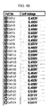
- FIG. 4A is a photograph illustrating a voltage of a defective fuel cell stack.
- FIG. 4B is a photograph illustrating a voltage of a normal fuel cell stack.
- a second electricity generating unit is defective, such that a voltage decreases to 0.338V.
- a reason why the voltage decreases is that a fuel passage is blocked, such that the fuel is not normally supplied.
- FIG. 4B the problem is solved by supplying the fuel in the reverse direction by a driving method of the fuel cell system according to the present invention.
Abstract
A fuel cell system comprising: a fuel cell stack provided with a fuel inlet, a fuel outlet, an oxidant inlet and an oxidant outlet; a fuel supply unit adapted to supply fuel to the fuel cell stack; an oxidant supply unit adapted to supply oxidant to the fuel cell stack; a fuel inflow pipe for supplying fuel from the fuel supply unit to the fuel inlet during a first operating condition; a fuel outflow pipe for discharging non-reacted fuel from the fuel outlet during the first operating condition; a first bypass pipe for supplying fuel from the fuel supply unit to the fuel outlet during a second operating condition; and a second bypass pipe for discharging non-reacted fuel from the fuel inlet during the second operating condition.
Description
- The present invention relates to a fuel cell system and a driving method thereof, and more particularly, to a fuel cell system that improves a structure of supplying fuel to a fuel cell stack.
- Fuel cells are devices that electrochemically generate power by using fuel (hydrogen or reformed gas) and oxidant (oxygen or air) and directly convert the fuel (hydrogen or reformed gas) and oxidant (oxygen or air) continuously supplied from the outside into electrical energy by an electrochemical reaction.
- Pure oxygen or air containing a large amount of oxygen is used as the oxidant of the fuel cell and pure hydrogen or fuel containing a large amount of hydrogen, which is generated by reforming hydrocarbon-based fuel (LNG, LPG, CH3OH etc.) is used as the fuel.
- Hereinafter, a direct methanol fuel cell (DMFC) will be primarily described for better comprehension and ease of description. The direct methanol fuel cell supplies high-concentration methanol to a fuel cell stack to generate electricity by reaction with the oxygen.
- When the fuel cell system is operated for a long time, impurities are stacked in a fuel passage of the fuel cell stack, such that the passage is blocked.
- As such, when the passage is blocked, a relevant cell must be replaced or repaired by disassembling the entire stack.
- Further, the inside of the stack is deteriorated when the fuel cell system is operated. This deterioration causes the lifespan of the fuel cell stack to be shortened.
- The above information disclosed in this Background section is only for enhancement of understanding of the background of the invention and therefore it may contain information that does not form the prior art that is already known in this country to a person of ordinary skill in the art.
- The present invention has been made in an effort to provide a fuel cell system that does not suffer from the above described problems of the prior art.
- Accordingly, a first aspect of the invention provides a fuel cell system as set out in
Claim 1. - Preferred features of this aspect of the invention are set out in
Claims 2 to 11. A further aspect of the invention provides a driving method for a fuel system as set out inClaim 12. Preferred features of this aspect of the invention are set out inClaims 13 to 15. - Embodiments of the invention therefore make it possible to remove impurities in the fuel cell stack and improve the lifespan of the fuel cell system by preventing deterioration of the stack through reducing blockages.
- Embodiments of the invention will be described by way of example, with refernence to the accompanying drawings, in which:
-
FIG. 1 is a schematic diagram of a fuel cell system according to a first embodiment of the present invention; -
FIG. 2 is an exploded perspective view illustrating a structure of the fuel cell stack shown inFIG. 1 ; -
FIG. 3 is a flowchart of a driving method of a fuel cell system according to an embodiment of the present invention; -
FIG. 4A is a photograph illustrating a voltage of a defective fuel cell stack; and -
FIG. 4B is a photograph illustrating a voltage of a normal fuel cell stack. - The present invention will be described more fully hereinafter with reference to the accompanying drawings, in which embodiments of the invention are shown. As those skilled in the art would realize, the described embodiments may be modified in various different ways, all without departing from the scope of the present invention.
-
FIG. 1 is a schematic diagram illustrating an entire configuration of a fuel cell system according to a first embodiment of the present invention. - The
fuel cell system 100 of this particular embodiment adopts a direct methanol fuel cell (DMFC) scheme that generates electrical energy by direct reaction of methanol and oxygen. However, the present invention is not limited thereto and a fuel cell system according to the invention may be configured by a direct oxidation fuel cell (DOFC) scheme that reacts liquid or gas fuel containing hydrogen, such as ethanol, LPG, LNG, gasoline, butane gas, etc. with oxygen. Further, the fuel cell system may be configured by a polymer electrode fuel cell (PEMFC) that uses the fuel by reforming the fuel into reformed gas containing sufficient hydrogen. The fuel used in thefuel cell system 100 generally represents hydrocarbon-based fuel in a liquid or gas state, such as methanol, ethanol, natural gas, LPG, etc. In addition, the fuel cell system may use oxygen gas stored in an additional storing means or air as oxidant that reacts with hydrogen. - The
fuel cell system 100 according to the this embodiment of the invention includes afuel cell stack 30 that generates power by using fuel and an oxidant, afuel supply unit 10 that supplies the fuel to thefuel cell stack 30, and anoxidant supply unit 20 that supplies the oxidant for generating electricity to thefuel cell stack 30. - The
fuel supply unit 10 is connected with thefuel cell stack 30 and includes afuel tank 12 that stores liquefied fuel and afuel pump 14 that is connected to thefuel tank 12. Thefuel pump 14 serves to discharge the liquefied fuel stored in thefuel tank 12 from the inside of thefuel tank 12 by a predetermined pumping force. In this particular embodiment, the fuel stored in thefuel supply unit 10 consists of high-concentration methanol. - The
oxidant supply unit 20 is connected with thefuel cell stack 30 and includes anoxidant pump 21 that suctions external air and supplies the external air to thefuel cell stack 30 by the predetermined pumping force. -
FIG. 2 is an exploded perspective view illustrating a structure of the fuel cell stack shown inFIG. 1 . - Referring to
FIGS. 1 and2 , thefuel cell stack 30 adopted in thefuel cell system 100 includes a plurality of electricity generatingunits 35 that generate electrical energy by inducing oxidation and reduction reactions of the fuel and the oxidant. Each of theelectricity generating units 35 represents a unit cell that generates the electricity and includes a membrane electrode assembly (MEA) 31 that oxidizes and reduces oxygen in the fuel and the oxidant and separators (also referred to as a bipolar plate in the art) 32 and 33 that supply the fuel and the oxidant to themembrane electrode assembly 31. - Each
electricity generating unit 35 has a structure in which theseparators membrane electrode assembly 31. Themembrane electrode assembly 31 includes an electrolyte membrane disposed at the center thereof, a cathode electrode disposed at one side of the electrolyte membrane, and an anode electrode disposed at the other side of the electrolyte membrane. - The
separators membrane electrode assembly 31 interposed therebetween. Theseparators membrane electrode assembly 31. At this time, the fuel passage is disposed at the anode electrode of themembrane electrode assembly 31 and the oxidant passage is disposed at the cathode electrode of themembrane electrode assembly 31. In addition, the electrolyte membrane enables ion exchange in which hydrogen ions generated from the anode electrode move to the cathode electrode and are bound to oxygen of the cathode electrode to generate water. - In the
fuel cell system 100, the plurality ofelectricity generating units 35 are successively arranged to constitute thefuel cell stack 30. Herein,end plates fuel cell stack 30 are installed at outermost parts of thefuel cell stack 30. - A
fuel inlet 37a for injecting the fuel to thefuel cell stack 30 and anoxidant inlet 37b for injecting the oxidant to the stack are formed in oneend plate 37. Afuel outlet 37c for discharging non-reacted fuel remaining after reaction at the anode electrode and anoxidant outlet 37d for discharging moisture and non-reacted air generated by a bonding reaction of hydrogen and oxygen at the cathode electrode are also formed in thisend plate 37. - The
other end plate 38 pressurizes the electricity generatingunits 35 with facing the oneend plate 37. In this embodiment, although theinlets outlets end plate 37, the present invention is not limited thereto. Theinlets end plate 37 and theoutlets other end plate 38. - The
fuel supply unit 10 is connected with thefuel inlet 37a through afuel inflow pipe 15 and theoxidant supply unit 20 is connected with theoxidant inlet 37b through anoxidant supply pipe 25. Further, afuel outflow pipe 43 is connected to thefuel outlet 37c and anoxidant outflow pipe 41 is connected to theoxidant outlet 37d. - The
fuel outflow pipe 43 and theoxidant outflow pipe 41 are connected with afuel inflow pipe 15 in order to recover non-reacted fuel and moisture. Afilter 56 is installed in thefuel inflow pipe 15 in order to remove impurities included in the fuel which is supplied to the fuel cell stack. - Meanwhile, a
first bypass pipe 45 that transfers the fuel transferred from thefuel supply unit 10 to thefuel outflow pipe 43 is installed between thefuel inflow pipe 15 and thefuel outflow pipe 43. Further, asecond bypass pipe 47 that transfers the fuel transferred from the non-reacted fuel discharged from thefuel inlet 37a to thefuel outflow pipe 43 is installed between thefuel inflow pipe 15 and thefuel outflow pipe 43. - In the
fuel inflow pipe 15, thefirst bypass pipe 45 is installed closer to thefuel supply unit 10 than thesecond bypass pipe 47 and thesecond bypass pipe 47 is installed closer to thefuel cell stack 30 than thefirst bypass pipe 45. In thefuel outflow pipe 43, thefirst bypass pipe 45 is installed closer to thefuel cell stack 30 than thesecond bypass pipe 47. - As a result, the
first bypass pipe 45 and thesecond bypass pipe 47 are not in communication with each other, but cross each other. - The
first bypass pipe 45 is connected to thefuel inflow pipe 15 through asupply valve 51 and thesecond bypass pipe 47 is connected to thefuel outflow pipe 43 through adischarge valve 53. Thesupply valve 51 and thedischarge valve 53 are each in the form of a 3-way valve. - The
fuel cell system 100 according to this embodiment further includes acontrol unit 60. When thefuel cell system 100 is defective in operation, thecontrol unit 60 controls thesupply valve 51 to allow thefuel supply unit 10 and thefirst bypass pipe 45 to be in communication with each other to inject the fuel into thefuel outlet 37c. - At this time, the
supply valve 51 intercepts connection between thefuel inflow pipe 15 and thefuel cell stack 30 to allow the fuel that is injected from thefuel supply unit 10 to flow through thefirst bypass pipe 45. - Further, the
control unit 60 controls thedischarge valve 53 to allow thesecond bypass pipe 47 and thefuel outflow pipe 43 to be in communication with each other to discharge the non-reacted fuel discharged from thefuel inlet 37a to thefuel outflow pipe 43. At this time, thedischarge valve 53 intercepts connection between thefuel outflow pipe 43 and thefuel cell stack 30, such that the non-reacted fuel is not injected into thefuel cell stack 30, but may be discharged. - As such, an operation in which the fuel is injected into the
fuel outlet 37c and the fuel is discharged to thefuel inlet 37a is referred to as a reverse operation. Meanwhile, an operation in which the fuel is injected into thefuel inlet 37a and the fuel is discharged from thefuel outlet 37c is referred to as a forward operation. The forward operation is a first operating condition and the reverse operation is a second operating condition. - The non-reacted fuel passes through the
fuel outflow pipe 43 then is supplied to thefuel inflow pipe 15 wherein the non-reacted fuel passes through thefilter 56. At this time, the impurities included in the non-reacted fuel may be filtered by thefilter 56. Hence, the impurities may be easily removed by changing thefilter 56 periodically. - As such, after the reverse operation is performed for a predetermined time, the
control unit 60 intercepts the connection between thefuel inflow pipe 15 and thefirst bypass pipe 45 and intercepts the connection between thefuel outflow pipe 43 and thesecond bypass pipe 47. In addition, thefuel inflow pipe 15 and thefuel inlet 37a are in communication with each other and thefuel outflow pipe 43 and thefuel outlet 37c are in communication with each other. - As a result, the fuel is again supplied to the
fuel inlet 37a through thefuel inflow pipe 15 and thefuel outlet 37c and thefuel outflow pipe 43 are in communication with each other to discharge the non-reacted fuel. - When the
first bypass pipe 45 and thesecond bypass pipe 47 are connected with thesupply valve 51 and thedischarge valve 53, low-concentration fuel is in contact with a part where high-concentration fuel flows and the high-concentration fuel is in contact with a part where the low-concentration fuel flows. As a result, thefuel cell stack 30 is reactivated, such that the durability and lifespan of the fuel cell stack are improved. - Further, the impurities accumulated in the
fuel cell stack 30 may be discharged to the outside by reversely injecting the fuel. -
FIG. 3 is a flowchart of a driving method of a fuel cell system according to of the present invention. - Referring to
FIG. 3 , the driving method includes the steps of injecting fuel into afuel outlet 37c (S101), discharging non-reacted fuel to afuel inlet 37a (S102), transferring the non-reacted fuel discharged to thefuel inlet 37a to a fuel outlet pipe 43 (S103), and removing impurities included in the non-reacted fuel (S104). - The step of injecting the fuel into the
fuel outlet 37c (S101) includes the steps of connecting abypass pipe 45 with afuel inflow pipe 15 and intercepting connection between thefuel inflow pipe 15 and thefuel inlet 37a. - The
fuel inflow pipe 15 and thefirst bypass pipe 45 are connected with each other by asupply valve 51 and thefuel inflow pipe 15 and thefuel inlet 37a are also intercepted from each other by thesupply valve 51. - That is, the
supply valve 51 closes a pipe connected from thefuel inflow pipe 15 to thefuel inlet 37a and opens a part connected with thefirst bypass pipe 45. - By the above-mentioned control, the fuel is injected into the
first bypass pipe 45 through thefuel inflow pipe 15 and the fuel injected into thefirst bypass pipe 45 may be injected into thefuel outlet 37c through thefuel outflow pipe 43 connected with thefirst bypass pipe 45. - Therefore, the step of injecting the fuel into the
fuel outlet 37c (S101) further includes the steps of transferring the fuel to thefirst bypass pipe 45 from thefuel inflow pipe 15, transferring the fuel to thefuel outflow pipe 43 from thefirst bypass pipe 45, and injecting the fuel to thefuel outlet 37c from thefuel outflow pipe 43. - As described above, the fuel transferred to the
fuel inflow pipe 15 from afuel supply unit 10 is injected into thefuel outlet 37c by passing through thefirst bypass pipe 45 and thefuel outflow pipe 43 in sequence. - The fuel injected into the
fuel outlet 37c reacts with oxidant in afuel cell stack 30 and the non-reacted fuel is discharged to thefuel inlet 37a. - The step of transferring the non-reacted fuel discharged to the
fuel inlet 37a to the fuel outflow pipe 43 (S103) includes the steps of connecting asecond bypass pipe 47 with thefuel outflow pipe 43 and intercepting connection between thefuel outflow pipe 43 and thefuel outlet 37c. - The
fuel outflow pipe 43 and thesecond bypass pipe 47 are connected with each other by adischarge valve 53 and thefuel outflow pipe 43 and thefuel outlet 37c are also intercepted from each other by thedischarge valve 53. - That is, the
discharge valve 53 closes a pipe connected from thefuel outflow pipe 43 to thefuel outlet 37c and opens a part connected with thesecond bypass pipe 47. - By the above-mentioned control, the fuel discharged from the
fuel inlet 37a is injected into thesecond bypass pipe 47 through thefuel inflow pipe 15 and the fuel injected into thesecond bypass pipe 47 may be discharged through thefuel outflow pipe 43 connected with thesecond bypass pipe 47. - Therefore, the step of transferring the non-reacted fuel discharged to the
fuel inlet 37a to the fuel outflow pipe 43 (S103) further includes the steps of transferring the fuel to thesecond bypass pipe 47 from thefuel inflow pipe 15 and transferring the fuel to thefuel outflow pipe 43 from thesecond bypass pipe 47. - As described above, the fuel transferred to the
fuel inflow pipe 15 from thefuel inlet 37a is discharged by passing through thesecond bypass pipe 47 and thefuel outflow pipe 43 in sequence. - As such, when the fuel is injected into the
fuel outlet 37c and the fuel is discharged to thefuel inlet 37a, the reverse operation is performed, thereby removing impurities. The impurities included in the fuel are filtered by thefilter 56, and the impurities created in thefuel cell stack 30 are basically expelled out by the flow pressure. On the contrary, when the impurities created in thefuel cell stack 30 block the inlet of passage under certain conditions, the fuel may not flow into theelectricity generating unit 35. In such a situation, if the inlet and outlet are exchanged and the fuel is to be flowed inversely, the impurities located at the inlet of passage may be expelled to thefuel outflow pipe 43. That impurities are transferred to thefuel inlet pipe 15 and then filtered at thefilter 56, afterwards never be able to flow into thefuel cell stack 30. Therefore, thefuel cell stack 30 may be used semipermanently if thefilter 56 is changed periodically. - When the fuel flows in a reverse direction, low-concentration fuel is in contact with a part where high-concentration flows and the high-concentration fuel is in contact with a part where the low-concentration fuel flows. As a result, the
fuel cell stack 30 is reactivated, such that the durability and lifespan of thefuel cell stack 30 are improved. - In the step of removing the impurities included in the non-reacted fuel (S104), the impurities are removed by using a
filter 56 installed in thefuel inflow pipe 15 during a process of inflow back to thefuel cell stack 30. The impurities may be included in the non-reacted fuel discharged to thefuel inlet 37a. The impurities are filtered by thefilter 56 installed in thefuel outflow pipe 43. - Meanwhile, the driving method of the
fuel cell system 100 according to this embodiment further includes the steps of injecting the fuel into thefuel inflow pipe 15 and thefuel inlet 37a and discharging the non-reacted fuel to thefuel outlet 37c and thefuel outflow pipe 43. Through these steps, the fuel is supplied in a forward direction. After a reverse operation is continuously performed for a predetermined time, the forward operation is also performed. - When an error occurs in the
fuel cell stack 30, the reverse operation is performed. In addition, in order to improve the durability, the reverse operation may be periodically performed for the predetermined time even when thefuel cell stack 30 has no error. - A
control unit 60 monitors a voltage of each of anelectricity generating units 35. When a voltage of a predeterminedelectricity generating unit 35 decreases to a reference voltage or less, thecontrol unit 60 can control thesupply valve 51 and thedischarge valve 53 so as to supply the fuel in the reverse direction. - When the voltage of each
electricity generating unit 35 is recovered to a normal voltage by supplying the fuel in the reverse direction, thecontrol unit 60 controls thesupply valve 51 and thedischarge valve 53 so as to supply the fuel in the forward direction again. - Further, by setting a time for which the fuel is supplied in the forward direction and a time for which the fuel is supplied in the reverse direction to the same value, the forward operation and the reverse operation may be alternately performed.
-
FIG. 4A is a photograph illustrating a voltage of a defective fuel cell stack.FIG. 4B is a photograph illustrating a voltage of a normal fuel cell stack. - Referring to
FIGS. 4A and4B , in this experiment, a direct methanol fuel cell having a current of approximately 1.72A and an output of approximately 17.5W is used. - As shown in
FIG. 4A , a second electricity generating unit is defective, such that a voltage decreases to 0.338V. A reason why the voltage decreases is that a fuel passage is blocked, such that the fuel is not normally supplied. In -
FIG. 4B , the problem is solved by supplying the fuel in the reverse direction by a driving method of the fuel cell system according to the present invention. - As shown in
FIG. 4B , impurities remaining in the fuel passage are removed, such that the voltage of the second electricity generating unit is recovered to 0.485V. As such, when the error occurs in the fuel cell, it is possible to very easily solve the problem without disassembling the fuel cell stack. - While this invention has been described in connection with embodiments thereof, it is to be understood that the invention is not limited to the disclosed embodiments, but, on the contrary, is intended to cover various modifications and equivalent arrangements included within the scope of the appended claims.
Claims (15)
- A fuel cell system comprising:a fuel cell stack provided with a fuel inlet, a fuel outlet, an oxidant inlet and an oxidant outlet;a fuel supply unit adapted to supply fuel to the fuel cell stack;an oxidant supply unit adapted to supply oxidant to the fuel cell stack;a fuel inflow pipe for supplying fuel from the fuel supply unit to the fuel inlet during a first operating condition;a fuel outflow pipe for discharging non-reacted fuel from the fuel outlet during the first operating condition;a first bypass pipe for supplying fuel from the fuel supply unit to the fuel outlet during a second operating condition; anda second bypass pipe for discharging non-reacted fuel from the fuel inlet during the second operating condition.
- A fuel cell system according to claim 1, wherein the first bypass pipe is connected between the fuel inflow pipe and the fuel outflow pipe.
- A fuel cell system according to claim 1 or 2, wherein the second bypass pipe is connected between the fuel inflow pipe and the fuel outflow pipe.
- A fuel cell system according to any preceding claim, comprising a first valve for directing fuel to the fuel inlet during the first operating condition and for directing fuel to the fuel outlet during the second operating condition.
- A fuel cell system according to any preceding claim, comprising a second valve for directing non-reacted fuel away from the fuel outlet during the first operating condition and for directing non-reacted fuel away from the fuel inlet during the second operating condition.
- A fuel cell system according to claim 1, wherein a first end of the first bypass pipe is connected to the fuel inflow pipe by a first valve and a second end of the first bypass pipe is connected to the fuel outflow pipe; a first end of the second bypass pipe is connected to the fuel inflow pipe and a second end of the second bypass pipe is connected to the fuel outflow pipe by a second valve; the first valve is adapted to direct fuel to the fuel inlet during the first operating condition and to direct fuel to the first bypass pipe during the second operating condition; and the second valve is adapted to direct non-reacted fuel away from the fuel outlet during the first operating condition and to direct non-reacted fuel away from the second bypass pipe during the second operating condition.
- A fuel cell system according to claim 6, wherein the first end of the second bypass pipe is connected to the fuel inflow pipe between the first valve and the fuel inlet, and the second end of the first bypass pipe is connected to the fuel outflow pipe between the second valve and the fuel outlet.
- A fuel cell system according to claim 6 or 7, further comprising a control unit adapted to monitor the operation of the fuel cell stack, determine whether the system should operate in accordance with the first operating condition or the second operating condition, and control at least one of the first and second valves in order to implement the determined said operating condition.
- A fuel cell system according to one of claims 6 to 8, wherein the first and second valves are three-way valves.
- A fuel cell system according to any preceding claim, wherein the second operating condition is adapted to rectify a blockage in the fuel cell stack.
- A fuel cell system according to any preceding claim, comprising a filter that is adapted to remove impurities from non-reacted fuel before the fuel is re-supplied to the fuel cell stack.
- A driving method for a fuel cell system that includes a fuel cell stack provided with a fuel inlet, a fuel outlet, an oxidant inlet and an oxidant outlet, the said method comprising the steps of:supplying fuel to the fuel inlet during a first operating condition;discharging non-reacted fuel from the fuel outlet during the first operating condition;supplying fuel to the fuel outlet during a second operating condition; anddischarging fuel from the fuel inlet during the second operating condition.
- A driving method according to claim 12, comprising directing non-reacted fuel via a filter prior to re-supplying it to the fuel cell stack.
- A driving method according to claim 12 or 13, comprising monitoring the voltage of a plurality of electricity generating units within the fuel cell stack and switching the operation of the fuel cell system from the first operating condition to the second operating condition when the voltage of at least one of the electricity generating units decreases to a reference voltage or less.
- A driving method according to one of claims 12 or 13, comprising switching the operation of the fuel cell system between the first operating condition and the second operating condition at predetermined intervals.
Applications Claiming Priority (2)
| Application Number | Priority Date | Filing Date | Title |
|---|---|---|---|
| US15069009P | 2009-02-06 | 2009-02-06 | |
| US12/631,688 US20100203402A1 (en) | 2009-02-06 | 2009-12-04 | Fuel cell system and driving method thereof |
Publications (1)
| Publication Number | Publication Date |
|---|---|
| EP2224531A1 true EP2224531A1 (en) | 2010-09-01 |
Family
ID=42102233
Family Applications (1)
| Application Number | Title | Priority Date | Filing Date |
|---|---|---|---|
| EP10250192A Withdrawn EP2224531A1 (en) | 2009-02-06 | 2010-02-04 | Fuel cell system and driving method thereof |
Country Status (5)
| Country | Link |
|---|---|
| US (1) | US20100203402A1 (en) |
| EP (1) | EP2224531A1 (en) |
| JP (1) | JP2010182675A (en) |
| KR (1) | KR20100090631A (en) |
| CN (1) | CN101800328A (en) |
Families Citing this family (2)
| Publication number | Priority date | Publication date | Assignee | Title |
|---|---|---|---|---|
| DE102013009629B4 (en) * | 2013-06-10 | 2019-09-12 | Carl Freudenberg Kg | Electrode module and arrangement with electrode modules |
| JP6954166B2 (en) * | 2018-02-14 | 2021-10-27 | トヨタ自動車株式会社 | Fuel cell system |
Citations (6)
| Publication number | Priority date | Publication date | Assignee | Title |
|---|---|---|---|---|
| JPH0311559A (en) * | 1989-06-08 | 1991-01-18 | Fuji Electric Co Ltd | Operating method of fuel battery |
| JPH05343082A (en) * | 1992-06-11 | 1993-12-24 | Tokyo Gas Co Ltd | Fuel cell power generation device |
| JPH06203861A (en) * | 1993-01-11 | 1994-07-22 | Toshiba Corp | Fuel cell power plant |
| JP2000348745A (en) * | 1999-06-03 | 2000-12-15 | Mitsubishi Electric Corp | Fuel cell |
| JP2002158023A (en) * | 2000-11-21 | 2002-05-31 | Toyota Central Res & Dev Lab Inc | Fuel cell system |
| JP2005166515A (en) * | 2003-12-04 | 2005-06-23 | Toyota Motor Corp | Fuel cell and fuel cell system |
-
2009
- 2009-12-04 US US12/631,688 patent/US20100203402A1/en not_active Abandoned
-
2010
- 2010-01-14 KR KR1020100003556A patent/KR20100090631A/en not_active Application Discontinuation
- 2010-02-01 JP JP2010020216A patent/JP2010182675A/en not_active Withdrawn
- 2010-02-04 EP EP10250192A patent/EP2224531A1/en not_active Withdrawn
- 2010-02-05 CN CN201010114343A patent/CN101800328A/en active Pending
Patent Citations (6)
| Publication number | Priority date | Publication date | Assignee | Title |
|---|---|---|---|---|
| JPH0311559A (en) * | 1989-06-08 | 1991-01-18 | Fuji Electric Co Ltd | Operating method of fuel battery |
| JPH05343082A (en) * | 1992-06-11 | 1993-12-24 | Tokyo Gas Co Ltd | Fuel cell power generation device |
| JPH06203861A (en) * | 1993-01-11 | 1994-07-22 | Toshiba Corp | Fuel cell power plant |
| JP2000348745A (en) * | 1999-06-03 | 2000-12-15 | Mitsubishi Electric Corp | Fuel cell |
| JP2002158023A (en) * | 2000-11-21 | 2002-05-31 | Toyota Central Res & Dev Lab Inc | Fuel cell system |
| JP2005166515A (en) * | 2003-12-04 | 2005-06-23 | Toyota Motor Corp | Fuel cell and fuel cell system |
Also Published As
| Publication number | Publication date |
|---|---|
| CN101800328A (en) | 2010-08-11 |
| KR20100090631A (en) | 2010-08-16 |
| JP2010182675A (en) | 2010-08-19 |
| US20100203402A1 (en) | 2010-08-12 |
Similar Documents
| Publication | Publication Date | Title |
|---|---|---|
| EP2226883B1 (en) | Fuel cell system | |
| US20070087233A1 (en) | System and method of controlling fuel cell shutdown | |
| US7247398B2 (en) | System stack contingency and efficiency switching | |
| KR20070068989A (en) | Sealing member for fuel cell, fuel cell, and method of manufacturing the fuel cell | |
| EP2216845B1 (en) | Fuel cell system | |
| JP2009526367A (en) | System and method of shutdown for fuel cell system operation and corrosion prevention | |
| EP2639869A1 (en) | Method for operating solid polymer fuel cell system, and solid polymer fuel cell system | |
| EP2224531A1 (en) | Fuel cell system and driving method thereof | |
| KR20090070838A (en) | Fuel cell system having hydrogen recycling apparatus | |
| JP2009140757A (en) | Fuel cell system | |
| EP1830428B1 (en) | A recovery unit for a fuel cell and method of controlling same | |
| US20100068570A1 (en) | Fuel cell system | |
| EP3252858B1 (en) | Fuel cell and method for operating the same | |
| JP2010140700A (en) | Solid polymer fuel cell power generation system | |
| KR101233323B1 (en) | Fuel cell system | |
| JP5602162B2 (en) | Purging method for fuel cell system | |
| JP2014063664A (en) | Method of starting fuel cell system | |
| KR101786316B1 (en) | Fuel cell system | |
| JP2004134199A (en) | Starting method of fuel cell | |
| KR101147209B1 (en) | Driving method of fuel cell system | |
| JP5311974B2 (en) | Starting method of fuel cell system | |
| US8889310B2 (en) | Fuel cell system and driving method for the same | |
| US20210323817A1 (en) | Hydrogen system and method of operating hydrogen system | |
| KR101408887B1 (en) | Fuel Cell System and Stack Purge Method thereof | |
| JP2023115601A (en) | Activation method for fuel cell stack and device therefor |
Legal Events
| Date | Code | Title | Description |
|---|---|---|---|
| PUAI | Public reference made under article 153(3) epc to a published international application that has entered the european phase |
Free format text: ORIGINAL CODE: 0009012 |
|
| 17P | Request for examination filed |
Effective date: 20100210 |
|
| AK | Designated contracting states |
Kind code of ref document: A1 Designated state(s): AT BE BG CH CY CZ DE DK EE ES FI FR GB GR HR HU IE IS IT LI LT LU LV MC MK MT NL NO PL PT RO SE SI SK SM TR |
|
| AX | Request for extension of the european patent |
Extension state: AL BA RS |
|
| STAA | Information on the status of an ep patent application or granted ep patent |
Free format text: STATUS: THE APPLICATION IS DEEMED TO BE WITHDRAWN |
|
| 18D | Application deemed to be withdrawn |
Effective date: 20110301 |