EP2224452A1 - Ph adjusting system and method of adjusting ph - Google Patents
Ph adjusting system and method of adjusting ph Download PDFInfo
- Publication number
- EP2224452A1 EP2224452A1 EP08712107A EP08712107A EP2224452A1 EP 2224452 A1 EP2224452 A1 EP 2224452A1 EP 08712107 A EP08712107 A EP 08712107A EP 08712107 A EP08712107 A EP 08712107A EP 2224452 A1 EP2224452 A1 EP 2224452A1
- Authority
- EP
- European Patent Office
- Prior art keywords
- adjuster
- adjusting
- storage tank
- adjusting apparatus
- water
- Prior art date
- Legal status (The legal status is an assumption and is not a legal conclusion. Google has not performed a legal analysis and makes no representation as to the accuracy of the status listed.)
- Granted
Links
Images




Classifications
-
- G—PHYSICS
- G21—NUCLEAR PHYSICS; NUCLEAR ENGINEERING
- G21C—NUCLEAR REACTORS
- G21C9/00—Emergency protection arrangements structurally associated with the reactor, e.g. safety valves provided with pressure equalisation devices
- G21C9/004—Pressure suppression
-
- G—PHYSICS
- G21—NUCLEAR PHYSICS; NUCLEAR ENGINEERING
- G21C—NUCLEAR REACTORS
- G21C15/00—Cooling arrangements within the pressure vessel containing the core; Selection of specific coolants
- G21C15/18—Emergency cooling arrangements; Removing shut-down heat
-
- G—PHYSICS
- G21—NUCLEAR PHYSICS; NUCLEAR ENGINEERING
- G21C—NUCLEAR REACTORS
- G21C17/00—Monitoring; Testing ; Maintaining
- G21C17/02—Devices or arrangements for monitoring coolant or moderator
- G21C17/022—Devices or arrangements for monitoring coolant or moderator for monitoring liquid coolants or moderators
- G21C17/0225—Chemical surface treatment, e.g. corrosion
-
- G—PHYSICS
- G21—NUCLEAR PHYSICS; NUCLEAR ENGINEERING
- G21D—NUCLEAR POWER PLANT
- G21D1/00—Details of nuclear power plant
- G21D1/02—Arrangements of auxiliary equipment
-
- Y—GENERAL TAGGING OF NEW TECHNOLOGICAL DEVELOPMENTS; GENERAL TAGGING OF CROSS-SECTIONAL TECHNOLOGIES SPANNING OVER SEVERAL SECTIONS OF THE IPC; TECHNICAL SUBJECTS COVERED BY FORMER USPC CROSS-REFERENCE ART COLLECTIONS [XRACs] AND DIGESTS
- Y02—TECHNOLOGIES OR APPLICATIONS FOR MITIGATION OR ADAPTATION AGAINST CLIMATE CHANGE
- Y02E—REDUCTION OF GREENHOUSE GAS [GHG] EMISSIONS, RELATED TO ENERGY GENERATION, TRANSMISSION OR DISTRIBUTION
- Y02E30/00—Energy generation of nuclear origin
-
- Y—GENERAL TAGGING OF NEW TECHNOLOGICAL DEVELOPMENTS; GENERAL TAGGING OF CROSS-SECTIONAL TECHNOLOGIES SPANNING OVER SEVERAL SECTIONS OF THE IPC; TECHNICAL SUBJECTS COVERED BY FORMER USPC CROSS-REFERENCE ART COLLECTIONS [XRACs] AND DIGESTS
- Y02—TECHNOLOGIES OR APPLICATIONS FOR MITIGATION OR ADAPTATION AGAINST CLIMATE CHANGE
- Y02E—REDUCTION OF GREENHOUSE GAS [GHG] EMISSIONS, RELATED TO ENERGY GENERATION, TRANSMISSION OR DISTRIBUTION
- Y02E30/00—Energy generation of nuclear origin
- Y02E30/30—Nuclear fission reactors
Definitions
- the present invention relates to a pH adjusting system and a pH adjusting method for adjusting pH in a reactor container at abnormal time of a nuclear reactor stored in the reactor container.
- a nuclear power plant including a pressurized water reactor As a nuclear power plant in the past, a nuclear power plant including a pressurized water reactor is known.
- a primary cooling system such as the pressurized water reactor or a steam generator is stored in a reactor container (see, for example, Non-Patent Document 1).
- a spray facility for spraying spray water into the reactor container is provided around the nuclear container on the assumption of an abnormal situation.
- this spray facility includes a water tank for refueling disposed on the outside of the reactor container and serving as a water source, a spray ring disposed in the reactor container, a first spray pipe that connects the water tank for refueling and the spray ring, and a spray pump interposed in the first spray pipe.
- a storage container recirculation sump that is provided at the bottom of the reactor container and stores the sprayed spray water is provided in this spray facility.
- the storage container recirculation sump is connected to the first spray pipe between water tank for refueling and the spray pump via a second spray pump.
- the spray facility operates, more specifically, the spray pump is driven to spray the spray water from the water tank for refueling into the reactor container via the spray ring, whereby the inside of the reactor container is cooled to reduce the pressure in the reactor container. Thereafter, the sprayed spray water is stored in the storage container recirculation sump and the stored spray water is sprayed from the spray ring again through the second spray pipe.
- the spray facility is configured such that the spray water circulates in the reactor container.
- an iodine removal chemical tank that stores an iodine removal chemical
- a spray eductor interposed in the first spray pipe
- a chemical injection flow path that connects the iodine removal chemical tank and the spray eductor
- an on-off valve interposed in the chemical injection flow path
- a mesh basket containing a pH adjuster such as trisodium phosphate is arranged on a base level near an outer peripheral wall in the nuclear reactor (on a floor of the storage container recirculation sump) (see, for example Non-Patent Document 2).
- a pH adjuster such as trisodium phosphate
- the storage container recirculation sump is filled with the spray water.
- the basket disposed on the floor of the storage container recirculation sump is submerged and the pH adjuster stored in the basket dissolves in the spray water.
- the spray water in which the pH adjuster dissolves is circulated in the reactor container by the spray facility. This makes it possible to adjust pH in the reactor container.
- the radioactive iodine can be kept in the solution by adjusting pH in the reactor container.
- the deterioration in durability of structural materials and various devices in the reactor container can be controlled by adjusting pH in the reactor container. Boric acid is dissolved in the light water to decelerate neutrons generated by the nuclear fission reaction. Therefore, the light water is low in pH and acidic. The recirculated water is likely to deteriorate durability of materials of devices and pipes that recirculate the light water for a long period after an accident. However, the deterioration in durability of the devices and the pipes can be controlled by adjusting pH in the reactor container to be neutral.
- Non-Patent Document 1 " Genkai Nuclear Power Plant, Application for Permission of a Change in the Nuclear Reactor (A Change in Nos. 3 and 4 Nuclear Reactor Facilities)", Kyushu Electric Power Co., Inc., April 1990 , Attached Document 8, p. 8-5-8 to 8-5-10 and p. 8-5-18
- Non-Patent Document 2 J. A. Reinhart Site Director/Fort Calhoun Station, "Fort Calhoun Station, Unit No.
- a pH adjusting system comprises an internal water storage tank that is disposed in a reactor container, which stores a nuclear reactor, and is capable of storing cooling water; and a pH adjusting apparatus that is disposed above the internal water storage tank and stores a pH adjuster.
- the pH adjusting apparatus clauses a pH-adjusted solution generated by dissolving or mixing the pH adjuster to flow out to the internal water storage tank below the pH adjusting apparatus.
- the pH adjuster may be prepared in a powder state.
- the pH adjusting system may further comprise a solvent injecting unit that is capable of injecting a solvent for dissolving or diluting the pH adjuster into the pH adjusting apparatus.
- the pH adjusting apparatus may dissolve or mix the pH adjuster in the solvent, which is injected by the solvent injecting unit, to generate a pH-adjusted solution and may cause the generated pH-adjusted solution to flow out to the internal water storage tank below the pH adjusting apparatus.
- the pH adjusting system may further comprise a spraying unit that is capable of spraying the cooling water stored in the internal water storage tank into an inside of the reactor container.
- the spraying unit may also function as the solvent injecting unit and the cooling water may be used as the solvent, and the pH adjusting apparatus may be disposed below the spraying unit.
- the pH adjusting system may further comprise an external water storage tank that is provided on an outside of the reactor container and is capable of storing the solvent.
- the solvent injecting unit may inject the solvent, which is stored in the external water storage tank, into the pH adjusting apparatus.
- the solvent injecting unit may inject the cooling water, which is stored in the internal water storage tank, into the pH adjusting apparatus as the solvent.
- the pH adjusting apparatus may include a pH adjuster, a basket containing the pH adjuster, and a basket housing container housing the basket.
- An inlet through which the solvent injected from the solvent injecting unit flows in, and an outlet from which the pH-adjusted solution generated by dissolving or mixing the pH adjuster in the solvent flows out to the internal water storage tank are formed in the basket housing container.
- the outlet of the basket housing container may include an overflow pipe, and a start edge of the overflow pipe is located at a bottom of the basket housing container.
- a terminal end of the overflow pipe may be connected to the internal water storage tank.
- the pH adjusting apparatus may further include a vent pipe provided in the overflow pipe to vent the overflow pipe.
- a pH adjusting system comprise a reactor container that stores a nuclear reactor; an internal water storage tank that is disposed in a reactor container and is capable of storing cooling water; a spraying unit that is capable of spraying the cooling water, which is stored in the internal water storage tank, to an inside of the reactor container at abnormal time; and a pH adjusting apparatus that is disposed above the internal water storage tank and below the spraying unit and stores a pH adjuster therein.
- the pH adjusting apparatus includes the pH adjuster, a basket containing the pH adjuster, and a basket housing container that houses the basket therein, and is formed therein an inlet through which the cooling water sprayed from the spraying unit flows in and an outlet from which the pH-adjusted solution generated by dissolving the pH adjuster in the cooling water flows out to the internal water storage tank.
- a pH adjusting system comprises a reactor container that stores a nuclear reactor; an internal water storage tank that is disposed in a reactor container and is capable of storing cooling water; a pH adjusting apparatus that is disposed above the internal water storage tank and stores a pH adjuster therein; and a solvent injecting unit that is capable of injecting the cooling water, which is stored in the internal water storage tank, into the pH adjusting apparatus as a solvent for dissolving or diluting the pH adjuster at abnormal time.
- the pH adjusting apparatus includes the pH adjuster, a basket containing the pH adjuster, and a basket housing container that houses the basket therein.
- the basket housing container includes an inlet through which the cooling water injected from the solvent injecting unit flows in and an outlet from which the pH-adjusted solution generated by dissolving the pH adjuster in the cooling water flows out to the internal water storage tank.
- a pH adjusting method for adjusting pH in a reactor container at abnormal time of a reactor stored in the reactor container comprises a pH-adjusted-solution generating for injecting a solvent for dissolving or diluting a pH adjuster into a pH adjusting apparatus that stores the pH adjuster therein and dissolving or mixing the pH adjuster in the solvent to generate a pH-adjusted solution; and a mixing for causing the pH-adjusted solution, which is generated at the pH-adjusted-solution generating, to flow into an internal water storage tank that is provided below the pH adjusting apparatus and stores cooling water and mixing the pH-adjusted solution in the cooling water.
- the pH adjusting method may further comprises a spraying for spraying the cooling water mixed with the pH-adjusted solution in the mixing into an inside of the reactor container.
- the pH adjusting apparatus can surely cause the pH-adjusted solution generated by dissolving or mixing the pH adjuster to flow into the internal water storage tank below the pH adjusting apparatus. Therefore, it is possible to dispose the pH adjusting apparatus above the internal water storage tank, mix the pH-adjusted solution in the cooling water, and suitably perform pH adjustment in the reactor container. In other words, even if there is no space for disposing the pH adjusting apparatus on the floor of the internal water storage tank, it is possible to dispose the pH adjusting apparatus in an arbitrary position above the internal water storage tank. It is preferable to dispose the pH adjusting apparatus in a free space in the reactor container.
- the pH adjuster can be prepared in a powder state, the pH adjuster can be prepared to be easily dissolved. This makes it possible to efficiently generate a pH-adjusted solution with the pH adjusting apparatus.
- the cooling water stored in the internal water storage tank is sprayed into the reactor container by the spraying unit, it is possible to efficiently cool the inside of the reactor container. Because the sprayed cooling water flows into the internal water storage tank again, it is possible to circulate the cooling water in the reactor container. Moreover, because the spraying unit also serves as the solvent injecting unit, it is possible to reduce the number of components of the pH adjusting system and simplify a configuration of the pH adjusting system.
- the solvent (the cooling water) is caused to flow into the basket housing container by the solvent injecting unit (the spraying mean) through the inlet in a state in which the basket containing the pH adjuster is stored in the basket housing container, it is possible to submerge the basket in the solvent. In other words, it is possible to dissolve or mix the pH adjuster in the solvent by submerging the pH adjuster in the solvent. This makes it possible to generate a pH-adjusted solution.
- the generated pH-adjusted solution can flow into the internal water storage tank through the outlet. Because the generated pH-adjusted solution flows into the internal water storage tank in a free fall, it is unnecessary to use a driving system such as an on-off valve or a pump.
- the outlet includes the overflow pipe and the start end point of the overflow pipe is located at the bottom of the basket housing container. Therefore, it is possible to cause the high-density pH-adjusted solution, which tends to stay at the bottom, to flow out to the internal water storage tank. In other words, the pH-adjusted solution moves further downward as the density is higher. Therefore, by adopting the configuration described above, it is possible to satisfactorily cause the pH-adjusted solution to flow out without causing the high-density pH-adjusted solution to stay at the bottom of the basket housing container.
- the pH adjusting system includes the vent pipe for opening the inside of the duct of the overflow pipe to the atmosphere. Therefore, a siphon effect due to filling of the overflow pipe with the solvent (the cooling water) is not caused.
- the cooling water is sprayed over the pH adjusting apparatus by the spraying unit at abnormal time, it is possible to cause the cooling water to flow into the basket housing container through the inlet.
- the basket housing container is filled with the cooling water and the basket is submerged.
- the pH adjuster is dissolved in the cooling water, the pH-adjusted solution is generated.
- the generated pH-adjusted solution flows into the internal water storage tank through the outlet.
- the cooling water is injected into the pH adjusting apparatus by the solvent injecting unit at abnormal time. Therefore, it is possible to cause the cooling water to flow into the basket housing container through the inlet.
- the basket housing container is filed with the cooling water and the basket is submerged.
- the pH-adjusted solution is generated.
- the generated pH-adjusted solution flows into the internal water storage tank through the outlet. It is possible to dispose the pH adjusting apparatus above the internal water storage tank by configuring the pH adjusting apparatus as described above. In other words, even if there is no space for disposing the pH adjusting apparatus on the floor of the internal water storage tank, it is possible to dispose the pH adjusting apparatus in an arbitrary position above the internal water storage tank.
- a pressurized water reactor (PWR) is used as a nuclear reactor.
- PWR pressurized water reactor
- the high-temperature light water is sent to a steam generator by a pump.
- the high-temperature light water is subjected to heat exchange with a secondary coolant to evaporate the secondary coolant.
- the evaporated secondary coolant (steam) is sent to a turbine to drive a generator, whereby power generation is performed.
- Fig. 1 is a schematic diagram of the nuclear power plant according to this embodiment.
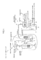
- Fig. 2 is a schematic diagram of a pH adjusting system according to this embodiment.
- Fig. 3 is a side sectional view of a reactor container.
- Fig. 4 is a plan sectional view of the reactor container. A configuration of the nuclear power plant is explained referring to Fig. 1 .
- the nuclear power plant 1 has a nuclear reactor 5 and a steam generator 7 connected to the nuclear reactor 5 via a pair of coolant pipes 6a and 6b made of a cold leg 6a and a hot leg 6b.
- a pressurizer 8 is interposed in the hot leg 6b of the pair of coolant pipes 6a and 6b.
- a coolant pump 9 is interposed in the cold leg 6a.
- a primary cooling system 3 of the nuclear power plant 1 includes the nuclear reactor 5, the pair of coolant pipes 6a and 6b, the steam generator 7, the pressurizer 8, and the coolant pump 9, which are housed in a reactor container 10.
- the light water as the primary coolant flows into the steam generator 7 from the nuclear reactor 5 through the hot leg 6b. Thereafter, the light water flowing out through the steam generator 7 flows into the nuclear reactor 5 through the cold leg 6a. In other words, the light water is circulating between the nuclear reactor 5 and the steam generator 7. Boric acid is dissolved in the light water to decelerate neutrons generated by the nuclear fission reaction of the nuclear reactor 5. The light water is acidic. In other words, the light water is used as a coolant and a neutron decelerator.
- the nuclear reactor 5 is the pressurized water reactor as described above.
- the inside of the nuclear reactor 5 is filled with the light water.
- a large number of fuel assemblies 15 are housed and a large number of control rods 16 that controls atomic fission of the fuel assemblies 15 are provided to be insertable in the fuel assemblies 15.
- the pressurizer 8 interposed in the hot leg 6 pressurizes the high-temperature light water to thereby control boiling of the light water.
- the steam generator 7 subjects the high-temperature light water to heat exchange with the secondary coolant to thereby evaporate the secondary coolant to generate steam and cool the high-temperature and high-pressure light water.
- the coolant pump 9 circulates the light water in the primary cooling system 3, sends the light water into the nuclear reactor 5 from the steam generator 7 via the cold leg 6a, and sends the light water into the steam generator 7 from the nuclear reactor 5 via the hot leg 6b.
- a series of operations in the primary cooling system 3 of the nuclear power plant 1 are explained.
- the heated light water is sent to the steam generator 7 by the coolant pump 9 via the hot leg 6b.
- the high-temperature light water passing through the hot leg 6b is pressurized by the pressurizer 8 and boiling thereof is controlled.
- the light water flows into the steam generator 7 in a high-temperature and high-pressure state.
- the high-temperature and high-pressure light water flowing into the steam generator 7 is cooled by being subjected to heat exchange with the secondary coolant.
- the cooled light water is sent to the nuclear reactor 5 by the coolant pump 9 via the cold leg 6a. When the cooled light water flows into the nuclear reactor 5, the nuclear reactor 5 is cooled.
- the nuclear power plant 1 has a turbine 22 connected to the steam generator 7 via a steam pipe 21, a steam condenser 23 connected to the turbine 22, and a feed water pump 24 interposed in a condensing and feeding pipe 26 that connect the steam condenser 23 and the steam generator 7.
- a secondary cooling system 20 includes these units.
- a secondary coolant circulating through the secondary cooling system 20 evaporates in the steam generator 7 to be gas (steam) and is changed from the gas to liquid in the steam condenser 23.
- a generator 25 is connected to the turbine 22.
- Cooling pipes 27 are disposed in the steam condenser 23.
- An intake pipe 28 for supplying cooling water (e.g., seawater) is connected to one of the cooling pipes 27.
- a drainage pipe 29 for draining the cooling water is connected to the other of the cooling pipes 27.
- the steam condenser 23 cools the steam, which flow in from the turbine 22, with the cooling pipe 27 to change the steam to liquid.
- the secondary coolant changed to the liquid is sent to the steam generator 7 by the feed water pump 24 via the condensing and feeding pipe 26.
- the secondary coolant sent to the steam generator 7 is subjected to heat exchange with the primary coolant to be changed to the steam again in the steam generator 7.
- a pH adjusting system 30 for cooling the inside of the reactor container 10 and controlling evaporation of radioactive iodine and a fall in durability of structural materials and the like is incorporated.
- the pH adjusting system 30 in this embodiment is explained below referring to Figs. 2 to 5 .
- This pH adjusting system 30 is a system for cooling the inside of the reactor container 10 and controlling evaporation of radioactive iodine and a fall in durability of structural materials and the like at abnormal time.
- the pH adjusting system 30 includes the reactor container 10 described above, a water pit for refueling 35 (an internal water storage tank) provided at the bottom in the reactor container 10, a spray facility 36 (solvent injecting means and spraying means) that can spray boric water (cooling water and the solvent) stored in the water pit for refueling 35 in the reactor container 10, and three pH adjusting apparatuses 37 for adjusting pH in the reactor container 10.
- the reactor container 10 integrally includes a container sealing section 40 formed in a hollow semispherical shape and a container main body section 41 formed in a bottomed cylindrical shape.
- the nuclear reactor 5, the pair of coolant pipes 6a and 6b, the steam generator 7, the pressurizer 8, and the coolant pump 9 are stored in the reactor container 10.
- the nuclear reactor 5 is disposed in the center of the reactor container 10.
- two steam generators 7 are disposed to be adjacent to each other on both sides of the nuclear reactor 5.
- An inspection rack 42 formed in a horseshoe shape in plan view is disposed in an upper part of a container main body section 41 of the reactor container 10 along an inner wall thereof (see Fig. 4 ).
- the inspection rack 42 includes a grating or the like.
- the three pH adjusting apparatuses 37 are disposed on this inspection rack 42.
- the inside of the reactor container 10 is configured such that boric acid water sprayed from a spray ring 45 described later returns to the water pit for refueling 35.
- the water pit for refueling 35 is disposed at the bottom of the reactor container 10 and is disposed in a horseshoe shape in plan view in a peripheral direction along an inner wall of the reactor container 10 (see Fig. 4 ).
- the inside of the water pit for refueling 35 is always filled with boric acid water.
- this boric acid water is used for refueling the fuel assemblies 15.
- this boric acid water is also used as cooling water for cooling the inside of the reactor container 10.
- This boric acid water is also used as a solvent of a pH adjuster described later.
- the water pit for refueling 35 is not limited to the configuration described above. A plurality of water pits for refueling can be disposed at equal intervals in the peripheral direction along the inner wall of the reactor container 10.
- the spray facility 36 includes four spray rings 45 (see Fig. 3 ) provided in a container ceiling section 40 in the reactor container 10, a spray pipe 47 that connects the four spray rings 45 and the water pit for refueling 35, and a spray pump 46 interposed in the spray pipe 47.
- the respective spray rings 45 are formed in ring shapes having different diameters.
- the four spray rings 45 are disposed in parallel to a center axis direction in a state in which the centers thereof are aligned and are disposed such that the diameters increase from a ceiling side to a bottom side.
- the diameter of the spray ring 45 located at the top of the container ceiling section 40 is the smallest and the diameter of a spray ring 45d located at the bottom is the largest.
- the spray pump 46 pumps up the boric acid water stored in the water pit for refueling 35 and supplies the boric acid water to the four spray rings 45.
- the three pH adjusting apparatuses 37 are disposed in arbitrary positions of the inspection rack 42, respectively.
- the pH adjusting apparatuses 37 are attached to an inner wall of the container main body section 41 and disposed at intervals in a peripheral direction of the container main body section 41.
- the three pH adjusting apparatuses 37 are disposed above the water pit for refueling 35 and disposed right below the spray ring 45d at the bottom (see Fig. 3 ). Consequently, the respective pH adjusting apparatuses 37 are disposed in water spray positions of water spray nozzles of the spray ring 45d at the bottom.
- each of the pH adjusting apparatuses 37 has a pH adjuster, a plurality of baskets 50 (one is shown in Fig. 5 ) that include the pH adjuster, a basket housing container 51 that houses the basket 50, an overflow pipe 52 provided in the basket housing container 51, and a vent pipe 53 provided in the overflow pipe 52.
- the number of baskets 50 housed in the basket housing container 51 is different for each of the three pH adjusting apparatuses 37.
- Prepared twenty-three baskets 50 in total are housed by being divided in such a manner that seven baskets, seven baskets, and nine baskets are housed in basket housing containers 51 of the respective pH adjusting apparatuses 37 (see Fig. 4 ).
- NaTB sodium tetraborate decahydrate
- TSP Trisodium phosphate
- Each of the baskets 50 containing the pH adjuster is formed in a rectangular parallelepiped shape.
- a part of the basket 50 e.g., upper and lower surfaces or sides
- the pH adjuster in the powder state does not flow out to the outside of the basket 50.
- the basket housing container 51 is formed in a box shape opened in an upper surface and is formed to be vent along the inner wall of the container main body section 41.
- a plurality of baskets 50 are housed in the basket housing container 51.
- the sprayed boric acid water is stored in the basket housing container 51 via openings of upper surfaces of the baskets 50 and submerges the baskets 50 housed therein.
- the openings of the upper surfaces of the baskets 50 are inlets of the boric acid water.
- An outlet of the basket housing container 51 includes the overflow pipe 52.
- the overflow pipe 52 is formed in a substantially reverse "U" shape.
- a start end of the overflow pipe 52 is located at the bottom in the basket housing container 51, the overflow pipe 52 extends upward from the start end along an inner wall of the basket housing container 51, bends in the horizontal direction in a sidewall upper part of the basket housing container 51, and pierces through the sidewall upper part.
- the overflow pipe 52 which pierces through the sidewall upper part, extends downward along an outer wall of the basket housing container 51, and a terminal end of the overflow pipe 52 is connected to the water pit for refueling 35.
- An aperture of the overflow pipe 52 is set to an aperture for preventing a duct of the overflow pipe 52 from being filled with the boric acid water, whereby occurrence of the siphon effect is controlled.
- terminal ends of a plurality of overflow pipes 52 are disposed at interval in a peripheral direction of the reactor container 10 with respect to the water pit for refueling 35 provided in the peripheral direction. This makes it possible to cause the pH-adjusted solution to evenly flow into the water pit for refueling 35. Therefore, it is possible to quickly and equally perform pH adjustment.
- the vent pipe 53 is formed in a substantially reverse "J" shape and disposed above the overflow pipe 52.
- the vent pipe 53 connects the inside and the outside of the overflow pipe 52.
- the vent pipe 53 opens the inside of the duct of the overflow pipe 52 to the atmosphere to prevent the inside of the duct of the overflow pipe 52 from being filled with the boric acid water. Consequently, the siphon effect due to the filling of the overflow pipe 52 with the boric acid water is not caused.
- the boric acid water sprayed from the spray ring 45d passes through the basket 50 and flows out from the overflow pipe 52, the pH adjuster in the basket 50 is always exposed to the flowing boric acid water.
- vent pipe 53 is not provided, an aperture of the overflow pipe 52 is set to an aperture with which the siphon effect is caused, and a strong flow of the boric acid water due to the siphon effect is repeatedly give to the pH adjuster in the basket 50 to facilitate the dissolution of the pH adjuster.
- the spray facility 36 operates.
- the spray pump 46 is driven to pump up the boric acid water from the water pit for refueling 35 and spray the pumped-up boric acid water into the reactor container 10 via the four spray rings 45.
- a part of the boric acid water sprayed from the spray ring 45d located at the bottom flows into the pH adjusting apparatus 37.
- the other parts of the boric acid water cool the inside of the reactor container 10.
- the boric acid water When the boric acid water is sprayed over the pH adjusting apparatus 37, the boric acid water flows into the basket housing container 51. Then, the basket housing container 51 is filled with the boric acid water and the basket 50 is submerged. When the basket 50 is submerged, because the pH adjuster is dissolved in the boric acid water, the pH-adjusted solution is generated (a pH-adjusted-solution generating ).
- the generated pH-adjusted solution flows into the water pit for refueling 35 in a free fall via the overflow pipe 52.
- a driving system such as an on-off valve or a pump. Therefore, a supply failure of the pH-adjusted solution due to a failure of the driving system is not caused. Consequently, it is possible to improve not only reliability of the pH adjusting apparatus 37 but also reliability of the pH adjusting system 30.
- the start end of the overflow pipe 52 is located at the bottom of the basket housing container 51, it is possible to appropriately lead the high-density pH-adjusted solution, which tends to stay at the bottom, to the overflow pipe 52. Moreover, because the terminal end of the overflow pipe 52 is connected to the water pit for refueling 35, it is possible to appropriately lead the pH-adjusted solution, which flows through the overflow pipe 52, to the water pit for refueling 35.
- the pH-adjusted solution which flows into the water pit for refueling 35, is mixed with the boric acid water in the water pit for refueling 35 (a mixing step). Thereafter, the boric acid water mixed with the pH-adjusted solution in the water pit for refueling 35 is pumped up the by spray pump 46 and the pumped-up boric acid water is sprayed into the reactor container 10 via the four spray rings 45 (a spraying step). Consequently, because the pH-adjusted solution circulates in the reactor container 10, pH in the reactor container 10 is adjusted and the inside of the reactor container 10 is cooled.
- the pH adjusting apparatus 37 can be configured to be capable of generating the pH-adjusted solution at abnormal time and cause the generated pH-adjusted solution to flow into the water pit for refueling 35 below the pH adjusting apparatus 37. Consequently, it is possible to dispose the pH adjusting apparatus 37 above the water pit for refueling 35. In other words, even if there is no space for disposing the pH adjusting apparatus 37 on the floor of the water pit for refueling 35, it is possible to dispose the pH adjusting apparatus 37 in an arbitrary position above the water pit for refueling 35. It is possible to effectively make use of a free space by disposing the pH adjusting apparatus 37 on the inspection rack 42.
- the boric acid water sprayed by the spray facility 36 falls on the pH adjusting apparatus 37.
- the spray facility 36 simultaneously performs spraying of the boric acid water into the reactor container and injection of the boric acid water into the pH adjusting apparatus. Therefore, it is unnecessary to provide a new solvent injection system that injects the boric acid water into the pH adjusting apparatus 37. Consequently, it is possible to simplify the configuration of the pH adjusting system 30 without increasing the number of components.
- the pH adjusting apparatus 37 is configured without using a driving system, a supply failure of the pH-adjusted solution due to an operation failure of the driving system does not occur. Consequently, it is possible to improve not only reliability of the pH adjusting apparatus 37 but also reliability of the pH adjusting system 30.
- a water collecting member formed in a funnel shape can be interposed between the spray ring 45d located at the bottom and the pH adjusting apparatus 37.
- Fig. 6 is a schematic diagram of a pH adjusting system at normal time according to the second embodiment.
- Fig. 7 is a schematic diagram of the pH adjusting system at abnormal time according to the second embodiment.
- the water pit for refueling 35 is provided at the bottom of the reactor container 10 and the boric acid water is always filled in the reactor container 10.
- the water pit for refueling 35 is not provided at the bottom of the reactor container 10.
- a water tank for refueling 205 is provided on the outside of the reactor container 10.
- the pH adjusting system 201 according to the second embodiment is specifically explained below.
- This pH adjusting system 201 includes the reactor container 10 that stores the nuclear reactor 5, the water tank 205 provided on the outside of the reactor container 10, a spray facility 206 that can spray boric acid water stored in the water tank for refueling 205 into the reactor container 10, and the pH adjusting apparatus 37 for adjusting pH in the reactor container 10.
- the reactor container 10 is configured to be capable of storing the boric acid water at the bottom thereof.
- the bottom of the reactor container 10 is in an empty state (see Fig. 6 ).
- the bottom of the reactor container 10 is filled with the boric acid water sprayed by the spray facility 206 (see Fig. 7 ). Therefore, the bottom of the reactor container 10 functions as an internal water storage tank that stores the boric acid water at abnormal time.
- the water tank for refueling 205 stores the boric acid water in the inside thereof.
- the boric acid water is used in refueling the fuel assemblies 15.
- the boric acid water is also used as cooling water for cooling the inside of the reactor container 10.
- the spray facility 206 includes four spray rings 207 (one is shown in the figure), a first spray pipe 208 that connects the four spray rings 207 and the water tank for refueling 205, a spray pump 209 interposed in the first spray pipe 208 on the outside of the reactor container 10, a second spray pipe 210 that connects the first spray pipe 208 between the water tank for refueling 205 and the spray pump 209 and the bottom of the reactor container 10, and a duct switching valve 211 disposed in a connecting portion of the first spray pipe 208 and the second spray pipe 210.
- the spray pump 209 is driven to supply the boric acid water from the water tank for refueling 205 to the spray rings 207.
- the duct switching valve 211 switches a duct to lead from the water tank for refueling 205 to the spray rings 207.
- the duct switching valve 211 switches the duct to lead from the bottom of the reactor container 10 to the spray rings 207. Then, the spray pump 209 supplies the boric acid water stored at the bottom of the reactor container 10 to the spray rings 207 and circulates the boric acid water in the reactor container 10.
- the pH adjusting apparatus 37 is configured in the same manner as the pH adjusting apparatus 37 according to the first embodiment and disposed on the inspection rack 42 provided in the reactor container 10. In other words, the pH adjusting apparatus 37 is disposed right below the spray ring 207 and disposed above the bottom of the reactor container 10 that functions as an internal water storage tank.
- the boric aid water is sprayed from the spray rings 207 and the sprayed boric acid water falls on the pH adjusting apparatus 37.
- the boric acid water is sprayed on the pH adjusting apparatus 37, the boric acid water flows into the basket housing container 51 and the basket 50 is submerged in the boric acid water.
- the pH-adjusted solution is generated by the pH adjusting apparatus 37 and the generated pH-adjusted solution flows into the bottom of the reactor container 10.
- the pH adjusting apparatus 37 includes the pH adjuster, the basket 50, the basket housing container 51, and the like.
- the pH adjusting apparatus 37 only has to be configured to dissolve the pH adjuster stored therein with the boric acid water to generate a pH-adjusted solution and cause the generated pH-adjusted solution to flow into the water pit for refueling 35 (the bottom of the reactor container).
- Fig. 8 is a schematic diagram of a pH adjusting system according to the third embodiment.
- injection of the boric acid water into the pH adjusting apparatus 37 is performed by the spray facility 36.
- injection of the boric acid water into the pH adjusting apparatus 37 is performed by a water filling facility 305 (solvent injecting means) instead of the spray facility 36.
- the pH adjusting system 301 includes the water filling facility 305 that injects the boric acid water into the pH adjusting apparatus 37.
- the water filling facility 305 has an injection nozzle 307 for injecting the boric acid water into the pH adjusting apparatus 37, a water filling pipe 308 that connects the injection nozzle 307 and the water pit for refueling 35, and an ECCS pump 309 interposed in the water filling pipe 308.
- the ECCS pump 309 is used in a reactor core system for emergency and supplies the boric acid water to the primary cooling system 3.
- the ECCS pump 309 is driven to pump up the boric acid water from the water pit for refueling 35 and inject the pumped-up boric acid water into the pH adjusting apparatus 37 via the injection nozzle 307.
- the boric acid water is injected into the pH adjusting apparatus 37, because the basket 50 is submerged in the boric acid water, the pH-adjusted solution is generated.
- the generated pH-adjusted solution flows into the water pit for refueling 35.
- the pH adjusting apparatus 37 can be configured to be capable of generating the pH-adjusted solution at abnormal time and cause the generated pH-adjusted solution to flow into the water pit for refueling 35 below the pH adjusting apparatus 37. Consequently, it is possible to dispose the pH adjusting apparatus 37 above the water pit for refueling 35. Unlike the first embodiment, it is unnecessary to dispose the pH adjusting apparatus 37 right below the spray ring 45d. Therefore, the pH adjusting apparatus 37 can be disposed in an arbitrary position without being restricted by a disposition position of the spray ring 45d. In this case, an upper part of the basket housing container 51 can be opened or can be closed by a lid.
- Fig. 9 is a schematic diagram of a pH adjusting system according to the modification of the third embodiment.
- the boric acid water is injected into the pH adjusting apparatus 37 by the ECCS pump 309.
- the boric acid water is injected into the pH adjusting apparatus 37 by an exclusive water filling pump 401 separate from the ECCS pump 309.
- the water filling facility 305 of the pH adjusting system 301 has the injection nozzle 307 for injecting the boric acid water into the pH adjusting apparatus 37, the water filling pipe 308 that connects the injection nozzle 307 and the water pit for refueling 35, and the water filling pump 401 interposed in the water filling pipe 308.
- the pH adjusting apparatus 37 can be configured to be capable of generating the pH-adjusted solution at abnormal time and cause the generated pH-adjusted solution to flow into the water pit for refueling 35 below the pH adjusting apparatus 37.
- the pH adjusting system and the pH adjusting method according to the present invention is suitable for adjusting pH in a reactor container at abnormal time of a nuclear reactor stored in the reactor container.
Landscapes
- Physics & Mathematics (AREA)
- Engineering & Computer Science (AREA)
- Plasma & Fusion (AREA)
- General Engineering & Computer Science (AREA)
- High Energy & Nuclear Physics (AREA)
- Structure Of Emergency Protection For Nuclear Reactors (AREA)
Abstract
Description
- The present invention relates to a pH adjusting system and a pH adjusting method for adjusting pH in a reactor container at abnormal time of a nuclear reactor stored in the reactor container.
- As a nuclear power plant in the past, a nuclear power plant including a pressurized water reactor is known. In this nuclear power plant, a primary cooling system such as the pressurized water reactor or a steam generator is stored in a reactor container (see, for example, Non-Patent Document 1). A spray facility for spraying spray water into the reactor container is provided around the nuclear container on the assumption of an abnormal situation.
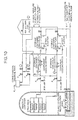
- As shown in
Fig. 10 , this spray facility includes a water tank for refueling disposed on the outside of the reactor container and serving as a water source, a spray ring disposed in the reactor container, a first spray pipe that connects the water tank for refueling and the spray ring, and a spray pump interposed in the first spray pipe. A storage container recirculation sump that is provided at the bottom of the reactor container and stores the sprayed spray water is provided in this spray facility. The storage container recirculation sump is connected to the first spray pipe between water tank for refueling and the spray pump via a second spray pump. - If an abnormal situation occurs, the pressure in the reactor container is increased by an evaporated primary coolant (light water). In such a case, the spray facility operates, more specifically, the spray pump is driven to spray the spray water from the water tank for refueling into the reactor container via the spray ring, whereby the inside of the reactor container is cooled to reduce the pressure in the reactor container. Thereafter, the sprayed spray water is stored in the storage container recirculation sump and the stored spray water is sprayed from the spray ring again through the second spray pipe.
In other words, the spray facility is configured such that the spray water circulates in the reactor container. - In the spray facility, to remove radioactive iodine contained in the evaporated light water, an iodine removal chemical tank that stores an iodine removal chemical, a spray eductor interposed in the first spray pipe, a chemical injection flow path that connects the iodine removal chemical tank and the spray eductor, and an on-off valve interposed in the chemical injection flow path are provided. Consequently, at abnormal time, the on-off valve is opened and the iodine removal chemical is injected into the first spray pipe via the spray eductor to mix the iodine removal chemical and the spray water. The mixture of the iodine removal chemical and the spray water is sprayed into the reactor container to remove the radioactive iodine in the reactor container.
- In this case, in general, strong alkali caustic soda is used as the iodine removal chemical. Therefore, to reduce burdens of management and operation of the chemical and a test of a chemical injection line valve, a pH adjusting system described below is also adopted.
- For example, it is known that a mesh basket containing a pH adjuster such as trisodium phosphate is arranged on a base level near an outer peripheral wall in the nuclear reactor (on a floor of the storage container recirculation sump) (see, for example Non-Patent Document 2). With this configuration, when the spray water is sprayed by the spray facility at abnormal time, the storage container recirculation sump is filled with the spray water. Then, the basket disposed on the floor of the storage container recirculation sump is submerged and the pH adjuster stored in the basket dissolves in the spray water. Thereafter, the spray water in which the pH adjuster dissolves is circulated in the reactor container by the spray facility. This makes it possible to adjust pH in the reactor container. The radioactive iodine can be kept in the solution by adjusting pH in the reactor container.
- The deterioration in durability of structural materials and various devices in the reactor container can be controlled by adjusting pH in the reactor container. Boric acid is dissolved in the light water to decelerate neutrons generated by the nuclear fission reaction. Therefore, the light water is low in pH and acidic. The recirculated water is likely to deteriorate durability of materials of devices and pipes that recirculate the light water for a long period after an accident. However, the deterioration in durability of the devices and the pipes can be controlled by adjusting pH in the reactor container to be neutral.
- Non-Patent Document 1: "Genkai Nuclear Power Plant, Application for Permission of a Change in the Nuclear Reactor (A Change in Nos. 3 and 4 Nuclear Reactor Facilities)", Kyushu Electric Power Co., Inc., April 1990, Attached
Document 8, p. 8-5-8 to 8-5-10 and p. 8-5-18 Non-Patent Document 2: J. A. Reinhart Site Director/Fort Calhoun Station, "Fort Calhoun Station, Unit No. 1 License Amendment Request (LAR) 'Change of Containment Building Sump Buffering Agent from Trisodium Phosphate to Sodium Tetraborate'", [online], August 21, 2006, U.S.NRC, [retrieved on October 17, 2007], Internet <URL: http://www.nrc.gov/ → select Electronic Reading Room → select Documents in ADAMS → select Web-based access → select Begin ADAMS Search → Input "ML062340039" → select Rank 5.(80)> - However, in the nuclear power plant, in design, it may be difficult to set the basket on the floor of the storage container recirculation sump. Such difficulty occurs, for example, when boric water is always filled in a water storage tank set at the bottom of the storage container or when a space for arranging the basket on the floor of the storage container recirculation sump cannot be secured.
- Therefore, it is an object of the present invention to provide a pH adjusting system and a pH adjusting method that can suitably perform pH adjustment in a reactor container even if it is difficult to dispose a pH adjusting apparatus on a floor of an internal water storage tank.
- According to an aspect of the present invention, a pH adjusting system comprises an internal water storage tank that is disposed in a reactor container, which stores a nuclear reactor, and is capable of storing cooling water; and a pH adjusting apparatus that is disposed above the internal water storage tank and stores a pH adjuster. The pH adjusting apparatus clauses a pH-adjusted solution generated by dissolving or mixing the pH adjuster to flow out to the internal water storage tank below the pH adjusting apparatus.
- In the pH adjusting system, the pH adjuster may be prepared in a powder state.
- The pH adjusting system may further comprise a solvent injecting unit that is capable of injecting a solvent for dissolving or diluting the pH adjuster into the pH adjusting apparatus. The pH adjusting apparatus may dissolve or mix the pH adjuster in the solvent, which is injected by the solvent injecting unit, to generate a pH-adjusted solution and may cause the generated pH-adjusted solution to flow out to the internal water storage tank below the pH adjusting apparatus.
- The pH adjusting system may further comprise a spraying unit that is capable of spraying the cooling water stored in the internal water storage tank into an inside of the reactor container. The spraying unit may also function as the solvent injecting unit and the cooling water may be used as the solvent, and the pH adjusting apparatus may be disposed below the spraying unit.
- The pH adjusting system may further comprise an external water storage tank that is provided on an outside of the reactor container and is capable of storing the solvent. The solvent injecting unit may inject the solvent, which is stored in the external water storage tank, into the pH adjusting apparatus.
- In the pH adjusting system, the solvent injecting unit may inject the cooling water, which is stored in the internal water storage tank, into the pH adjusting apparatus as the solvent.
- In the pH adjusting system, the pH adjusting apparatus may include a pH adjuster, a basket containing the pH adjuster, and a basket housing container housing the basket. An inlet through which the solvent injected from the solvent injecting unit flows in, and an outlet from which the pH-adjusted solution generated by dissolving or mixing the pH adjuster in the solvent flows out to the internal water storage tank are formed in the basket housing container.
- In the pH adjusting system, the outlet of the basket housing container may include an overflow pipe, and a start edge of the overflow pipe is located at a bottom of the basket housing container.
- In the pH adjusting system, a terminal end of the overflow pipe may be connected to the internal water storage tank.
- In the pH adjusting system, the pH adjusting apparatus may further include a vent pipe provided in the overflow pipe to vent the overflow pipe.
- According to another aspect of the present invention, a pH adjusting system comprise a reactor container that stores a nuclear reactor; an internal water storage tank that is disposed in a reactor container and is capable of storing cooling water; a spraying unit that is capable of spraying the cooling water, which is stored in the internal water storage tank, to an inside of the reactor container at abnormal time; and a pH adjusting apparatus that is disposed above the internal water storage tank and below the spraying unit and stores a pH adjuster therein. The pH adjusting apparatus includes the pH adjuster, a basket containing the pH adjuster, and a basket housing container that houses the basket therein, and is formed therein an inlet through which the cooling water sprayed from the spraying unit flows in and an outlet from which the pH-adjusted solution generated by dissolving the pH adjuster in the cooling water flows out to the internal water storage tank.
- According to still another aspect of the present invention, a pH adjusting system comprises a reactor container that stores a nuclear reactor; an internal water storage tank that is disposed in a reactor container and is capable of storing cooling water; a pH adjusting apparatus that is disposed above the internal water storage tank and stores a pH adjuster therein; and a solvent injecting unit that is capable of injecting the cooling water, which is stored in the internal water storage tank, into the pH adjusting apparatus as a solvent for dissolving or diluting the pH adjuster at abnormal time. The pH adjusting apparatus includes the pH adjuster, a basket containing the pH adjuster, and a basket housing container that houses the basket therein. The basket housing container includes an inlet through which the cooling water injected from the solvent injecting unit flows in and an outlet from which the pH-adjusted solution generated by dissolving the pH adjuster in the cooling water flows out to the internal water storage tank.
- According to still another aspect of the present invention, a pH adjusting method for adjusting pH in a reactor container at abnormal time of a reactor stored in the reactor container comprises a pH-adjusted-solution generating for injecting a solvent for dissolving or diluting a pH adjuster into a pH adjusting apparatus that stores the pH adjuster therein and dissolving or mixing the pH adjuster in the solvent to generate a pH-adjusted solution; and a mixing for causing the pH-adjusted solution, which is generated at the pH-adjusted-solution generating, to flow into an internal water storage tank that is provided below the pH adjusting apparatus and stores cooling water and mixing the pH-adjusted solution in the cooling water.
- The pH adjusting method may further comprises a spraying for spraying the cooling water mixed with the pH-adjusted solution in the mixing into an inside of the reactor container.
- With the pH adjusting system according to claim 1, the pH adjusting apparatus can surely cause the pH-adjusted solution generated by dissolving or mixing the pH adjuster to flow into the internal water storage tank below the pH adjusting apparatus. Therefore, it is possible to dispose the pH adjusting apparatus above the internal water storage tank, mix the pH-adjusted solution in the cooling water, and suitably perform pH adjustment in the reactor container. In other words, even if there is no space for disposing the pH adjusting apparatus on the floor of the internal water storage tank, it is possible to dispose the pH adjusting apparatus in an arbitrary position above the internal water storage tank. It is preferable to dispose the pH adjusting apparatus in a free space in the reactor container. This makes it possible to effectively make use of the free space and dispose the pH adjusting apparatus without changing an exiting configuration. When the pH adjuster is in a solid state, the pH adjuster is dissolved into the pH-adjusted solution. When the pH adjuster is in a liquid state, the pH adjuster is diluted into the pH-adjusted solution.
- With the pH adjusting system according to claim 2, because the pH adjuster can be prepared in a powder state, the pH adjuster can be prepared to be easily dissolved. This makes it possible to efficiently generate a pH-adjusted solution with the pH adjusting apparatus.
- With the pH adjusting system according to
claim 3, it is possible to inject the solvent into the pH adjusting apparatus by the solvent injecting unit. Therefore, it is possible to dissolve or mix the pH adjuster in the solvent to generate a pH-adjusted solution. - With the pH adjusting system according to claim 4, because the cooling water stored in the internal water storage tank is sprayed into the reactor container by the spraying unit, it is possible to efficiently cool the inside of the reactor container. Because the sprayed cooling water flows into the internal water storage tank again, it is possible to circulate the cooling water in the reactor container. Moreover, because the spraying unit also serves as the solvent injecting unit, it is possible to reduce the number of components of the pH adjusting system and simplify a configuration of the pH adjusting system.
- With the pH adjusting system according to
claim 5, it is possible to provide the external water storage tank and inject the solvent stored in the external water storage tank into the pH adjusting apparatus. Therefore, because it is unnecessary to dispose the pH adjusting apparatus right below the spraying unit unlike the pH adjusting apparatus according to claim 4, it is possible to improve a degree of freedom of a disposition position of the pH adjusting apparatus. - With the pH adjusting system according to claim 6, it is possible to inject the cooling water stored in the internal water storage tank into the pH adjusting apparatus as the solvent. Therefore, because it is unnecessary to dispose the pH adjusting apparatus right below the spraying unit unlike the pH adjusting apparatus according to claim 4, it is possible to improve a degree of freedom of a disposition position of the pH adjusting apparatus.
- With the pH adjusting system according to
claim 7, because the solvent (the cooling water) is caused to flow into the basket housing container by the solvent injecting unit (the spraying mean) through the inlet in a state in which the basket containing the pH adjuster is stored in the basket housing container, it is possible to submerge the basket in the solvent. In other words, it is possible to dissolve or mix the pH adjuster in the solvent by submerging the pH adjuster in the solvent. This makes it possible to generate a pH-adjusted solution. The generated pH-adjusted solution can flow into the internal water storage tank through the outlet. Because the generated pH-adjusted solution flows into the internal water storage tank in a free fall, it is unnecessary to use a driving system such as an on-off valve or a pump. In other words, it is possible to supply the pH-adjusted solution to the internal water storage tank simply by injecting the solvent into the basket housing container. Consequently, because a supply failure of the pH-adjusted solution due to an operation failure of the driving system is not caused, it is possible to improve not only reliability of the pH adjusting apparatus and but also reliability of the pH adjusting system. Because the solvent in the basket housing container flows from the inlet to the outlet, compared with a method of simply submerging the basket as in the past, it is possible to efficiently dissolve the pH adjuster. It is preferable to configure the basket using a mesh or the like. - With the pH adjusting system according to
claim 8, the outlet includes the overflow pipe and the start end point of the overflow pipe is located at the bottom of the basket housing container. Therefore, it is possible to cause the high-density pH-adjusted solution, which tends to stay at the bottom, to flow out to the internal water storage tank. In other words, the pH-adjusted solution moves further downward as the density is higher. Therefore, by adopting the configuration described above, it is possible to satisfactorily cause the pH-adjusted solution to flow out without causing the high-density pH-adjusted solution to stay at the bottom of the basket housing container. - With the pH adjusting system according to claim 9, because the terminal end of the overflow pipe is connected to the internal water storage tank, it is possible to appropriately lead the pH-adjusted solution to the internal water storage tank.
- With the pH adjusting system according to
claim 10, the pH adjusting system includes the vent pipe for opening the inside of the duct of the overflow pipe to the atmosphere. Therefore, a siphon effect due to filling of the overflow pipe with the solvent (the cooling water) is not caused. - With the pH adjusting system according to claim 11, because the cooling water is sprayed over the pH adjusting apparatus by the spraying unit at abnormal time, it is possible to cause the cooling water to flow into the basket housing container through the inlet. When the cooling water flows into the basket housing container, the basket housing container is filled with the cooling water and the basket is submerged. When the basket is submerged, because the pH adjuster is dissolved in the cooling water, the pH-adjusted solution is generated. The generated pH-adjusted solution flows into the internal water storage tank through the outlet. By configuring the pH adjusting apparatus as described above, it is possible to dispose the pH adjusting apparatus above the internal water storage tank. In other words, even if there is no space for disposing the pH adjusting apparatus on the floor of the internal water storage tank, it is possible to dispose the pH adjusting apparatus in an arbitrary position above the internal water storage tank. Because the generated pH-adjusted solution is caused to flow into the internal water storage tank in a free fall, it is unnecessary to use a driving system such as an on-off valve or a pump. In other words, it is possible to supply the pH-adjusted solution to the internal water storage tank simply by injecting the solvent into the basket housing container. Consequently, because a supply failure of the pH-adjusted solution due to an operation failure of the driving system is not caused, it is possible to improve not only reliability of the pH adjusting apparatus but also reliability of the pH adjusting system.
- With the pH adjusting system according to claim 12, the cooling water is injected into the pH adjusting apparatus by the solvent injecting unit at abnormal time. Therefore, it is possible to cause the cooling water to flow into the basket housing container through the inlet. When the cooling water flows into the basket housing container, the basket housing container is filed with the cooling water and the basket is submerged. When the basket is submerged, because the pH adjuster is dissolved in the cooling water, the pH-adjusted solution is generated. The generated pH-adjusted solution flows into the internal water storage tank through the outlet. It is possible to dispose the pH adjusting apparatus above the internal water storage tank by configuring the pH adjusting apparatus as described above. In other words, even if there is no space for disposing the pH adjusting apparatus on the floor of the internal water storage tank, it is possible to dispose the pH adjusting apparatus in an arbitrary position above the internal water storage tank.
- With the pH adjusting method according to claim 13, it is possible to dispose the pH adjusting apparatus above the internal water storage tank provided in the reactor container and suitably perform adjustment of pH in the reactor container.
- With the pH adjusting method according to claim 14, it is possible to spray the cooling water mixed with the pH-adjusted solution into the reactor container. This makes it possibly to satisfactorily perform pH adjustment in the reactor container.
-
-
Fig. 1 is a schematic diagram of a nuclear power plant according to a first embodiment; -
Fig. 2 is a schematic diagram of a pH adjusting system according to the first embodiment; -
Fig. 3 is a side sectional view of a reactor container; -
Fig. 4 is a plan sectional view of the reactor container; -
Fig. 5 is a schematic diagram of a pH adjusting apparatus according to the first embodiment; -
Fig. 6 is a schematic diagram of a pH adjusting system at normal time according to a second embodiment; -
Fig. 7 is a schematic diagram of the pH adjusting system at abnormal time according to the second embodiment; -
Fig. 8 is a schematic diagram of a pH adjusting system according to a third embodiment; -
Fig. 9 is a schematic diagram of a pH adjusting system according to modification of the third embodiment; and -
Fig. 10 is a system explanatory diagram of a spray facility in the past. -
- 1
- nuclear power plant
- 5
- nuclear reactor
- 10
- reactor container
- 30
- pH adjusting system
- 35
- water pit for refueling
- 36
- spray facility
- 37
- pH adjusting apparatus
- 42
- inspection rack
- 45
- spray ring
- 46
- spray pump
- 50
- basket
- 51
- basket housing container
- 52
- overflow pipe
- 53
- vent pipe
- 201
- pH adjusting system (second embodiment)
- 205
- water tank for refueling
- 301
- pH adjusting system (third embodiment)
- 305
- water filling facility
- 307
- injection nozzle
- 308
- water filling pipe
- 309
- ECCS pump
- 401
- water filling pump
- A nuclear power plant to which a pH adjusting system according to the present invention is applied is explained below referring to the attached drawings. The present invention is not limited by embodiments described below.
- In a nuclear power plant according to this embodiment, a pressurized water reactor (PWR) is used as a nuclear reactor. In a pressurized water nuclear power plant, after light water as a primary coolant is heated in the nuclear reactor, the high-temperature light water is sent to a steam generator by a pump. In the nuclear power plant, the high-temperature light water is subjected to heat exchange with a secondary coolant to evaporate the secondary coolant. The evaporated secondary coolant (steam) is sent to a turbine to drive a generator, whereby power generation is performed.
-
Fig. 1 is a schematic diagram of the nuclear power plant according to this embodiment.Fig. 2 is a schematic diagram of a pH adjusting system according to this embodiment.Fig. 3 is a side sectional view of a reactor container.Fig. 4 is a plan sectional view of the reactor container. A configuration of the nuclear power plant is explained referring toFig. 1 . - As shown in
Fig. 1 , the nuclear power plant 1 has anuclear reactor 5 and asteam generator 7 connected to thenuclear reactor 5 via a pair ofcoolant pipes cold leg 6a and ahot leg 6b. Apressurizer 8 is interposed in thehot leg 6b of the pair ofcoolant pipes cold leg 6a. Aprimary cooling system 3 of the nuclear power plant 1 includes thenuclear reactor 5, the pair ofcoolant pipes steam generator 7, thepressurizer 8, and the coolant pump 9, which are housed in areactor container 10. - In the configuration described above, the light water as the primary coolant flows into the
steam generator 7 from thenuclear reactor 5 through thehot leg 6b. Thereafter, the light water flowing out through thesteam generator 7 flows into thenuclear reactor 5 through thecold leg 6a. In other words, the light water is circulating between thenuclear reactor 5 and thesteam generator 7. Boric acid is dissolved in the light water to decelerate neutrons generated by the nuclear fission reaction of thenuclear reactor 5. The light water is acidic. In other words, the light water is used as a coolant and a neutron decelerator. - The
nuclear reactor 5 is the pressurized water reactor as described above. The inside of thenuclear reactor 5 is filled with the light water. In thenuclear reactor 5, a large number offuel assemblies 15 are housed and a large number ofcontrol rods 16 that controls atomic fission of thefuel assemblies 15 are provided to be insertable in thefuel assemblies 15. - When the
fuel assemblies 15 are subjected to atomic fission while the atomic fission reaction is controlled by thecontrol rods 16, thermal energy is generated by this atomic fission. The generated thermal energy heats the light water and the heated light water is sent to thesteam generator 7 via thehot leg 6b. On the other hand, the light water sent from thesteam generator 7 via thecold leg 6a flows into thenuclear reactor 5 and cools the inside of thenuclear reactor 5. - The
pressurizer 8 interposed in the hot leg 6 pressurizes the high-temperature light water to thereby control boiling of the light water. Thesteam generator 7 subjects the high-temperature light water to heat exchange with the secondary coolant to thereby evaporate the secondary coolant to generate steam and cool the high-temperature and high-pressure light water. The coolant pump 9 circulates the light water in theprimary cooling system 3, sends the light water into thenuclear reactor 5 from thesteam generator 7 via thecold leg 6a, and sends the light water into thesteam generator 7 from thenuclear reactor 5 via thehot leg 6b. - A series of operations in the
primary cooling system 3 of the nuclear power plant 1 are explained. When the light water is heated by the thermal energy generated by the atomic fission reaction in thenuclear reactor 5, the heated light water is sent to thesteam generator 7 by the coolant pump 9 via thehot leg 6b. The high-temperature light water passing through thehot leg 6b is pressurized by thepressurizer 8 and boiling thereof is controlled. The light water flows into thesteam generator 7 in a high-temperature and high-pressure state. The high-temperature and high-pressure light water flowing into thesteam generator 7 is cooled by being subjected to heat exchange with the secondary coolant. The cooled light water is sent to thenuclear reactor 5 by the coolant pump 9 via thecold leg 6a. When the cooled light water flows into thenuclear reactor 5, thenuclear reactor 5 is cooled. - The nuclear power plant 1 has a
turbine 22 connected to thesteam generator 7 via asteam pipe 21, asteam condenser 23 connected to theturbine 22, and afeed water pump 24 interposed in a condensing and feedingpipe 26 that connect thesteam condenser 23 and thesteam generator 7. Asecondary cooling system 20 includes these units. A secondary coolant circulating through thesecondary cooling system 20 evaporates in thesteam generator 7 to be gas (steam) and is changed from the gas to liquid in thesteam condenser 23. Agenerator 25 is connected to theturbine 22. - When the steam flows into the
turbine 22 from thesteam generator 7 via thesteam pipe 21, theturbine 22 rotates. When theturbine 22 rotates, thegenerator 25 connected to theturbine 22 performs heat generation. Thereafter, the steam flowing out from theturbine 22 flows into thesteam condenser 23. Coolingpipes 27 are disposed in thesteam condenser 23. Anintake pipe 28 for supplying cooling water (e.g., seawater) is connected to one of the coolingpipes 27. Adrainage pipe 29 for draining the cooling water is connected to the other of the coolingpipes 27. Thesteam condenser 23 cools the steam, which flow in from theturbine 22, with the coolingpipe 27 to change the steam to liquid. The secondary coolant changed to the liquid is sent to thesteam generator 7 by thefeed water pump 24 via the condensing and feedingpipe 26. The secondary coolant sent to thesteam generator 7 is subjected to heat exchange with the primary coolant to be changed to the steam again in thesteam generator 7. - In the nuclear power plant 1, a
pH adjusting system 30 for cooling the inside of thereactor container 10 and controlling evaporation of radioactive iodine and a fall in durability of structural materials and the like is incorporated. ThepH adjusting system 30 in this embodiment is explained below referring toFigs. 2 to 5 . - This
pH adjusting system 30 is a system for cooling the inside of thereactor container 10 and controlling evaporation of radioactive iodine and a fall in durability of structural materials and the like at abnormal time. As shown inFigs. 2 and3 , thepH adjusting system 30 includes thereactor container 10 described above, a water pit for refueling 35 (an internal water storage tank) provided at the bottom in thereactor container 10, a spray facility 36 (solvent injecting means and spraying means) that can spray boric water (cooling water and the solvent) stored in the water pit for refueling 35 in thereactor container 10, and threepH adjusting apparatuses 37 for adjusting pH in thereactor container 10. - As shown in
Fig. 3 , thereactor container 10 integrally includes acontainer sealing section 40 formed in a hollow semispherical shape and a containermain body section 41 formed in a bottomed cylindrical shape. Thenuclear reactor 5, the pair ofcoolant pipes steam generator 7, thepressurizer 8, and the coolant pump 9 are stored in thereactor container 10. Thenuclear reactor 5 is disposed in the center of thereactor container 10. For example, twosteam generators 7 are disposed to be adjacent to each other on both sides of thenuclear reactor 5. Aninspection rack 42 formed in a horseshoe shape in plan view is disposed in an upper part of a containermain body section 41 of thereactor container 10 along an inner wall thereof (seeFig. 4 ). Theinspection rack 42 includes a grating or the like. The threepH adjusting apparatuses 37 are disposed on thisinspection rack 42. The inside of thereactor container 10 is configured such that boric acid water sprayed from aspray ring 45 described later returns to the water pit for refueling 35. - The water pit for refueling 35 is disposed at the bottom of the
reactor container 10 and is disposed in a horseshoe shape in plan view in a peripheral direction along an inner wall of the reactor container 10 (seeFig. 4 ). The inside of the water pit for refueling 35 is always filled with boric acid water. Usually, this boric acid water is used for refueling thefuel assemblies 15. However, at abnormal time of thereactor 5, this boric acid water is also used as cooling water for cooling the inside of thereactor container 10. This boric acid water is also used as a solvent of a pH adjuster described later. The water pit for refueling 35 is not limited to the configuration described above. A plurality of water pits for refueling can be disposed at equal intervals in the peripheral direction along the inner wall of thereactor container 10. - As shown in
Fig. 2 , thespray facility 36 includes four spray rings 45 (seeFig. 3 ) provided in acontainer ceiling section 40 in thereactor container 10, aspray pipe 47 that connects the four spray rings 45 and the water pit for refueling 35, and aspray pump 46 interposed in thespray pipe 47. - As shown in
Fig. 3 , the respective spray rings 45 are formed in ring shapes having different diameters. The four spray rings 45 are disposed in parallel to a center axis direction in a state in which the centers thereof are aligned and are disposed such that the diameters increase from a ceiling side to a bottom side. The diameter of thespray ring 45 located at the top of thecontainer ceiling section 40 is the smallest and the diameter of aspray ring 45d located at the bottom is the largest. Thespray pump 46 pumps up the boric acid water stored in the water pit for refueling 35 and supplies the boric acid water to the four spray rings 45. - As shown in
Fig. 4 , the threepH adjusting apparatuses 37 are disposed in arbitrary positions of theinspection rack 42, respectively. ThepH adjusting apparatuses 37 are attached to an inner wall of the containermain body section 41 and disposed at intervals in a peripheral direction of the containermain body section 41. In other words, the threepH adjusting apparatuses 37 are disposed above the water pit for refueling 35 and disposed right below thespray ring 45d at the bottom (seeFig. 3 ). Consequently, the respectivepH adjusting apparatuses 37 are disposed in water spray positions of water spray nozzles of thespray ring 45d at the bottom. - As shown in
Fig. 5 , each of thepH adjusting apparatuses 37 has a pH adjuster, a plurality of baskets 50 (one is shown inFig. 5 ) that include the pH adjuster, abasket housing container 51 that houses thebasket 50, anoverflow pipe 52 provided in thebasket housing container 51, and avent pipe 53 provided in theoverflow pipe 52. The number ofbaskets 50 housed in thebasket housing container 51 is different for each of the threepH adjusting apparatuses 37. Prepared twenty-threebaskets 50 in total are housed by being divided in such a manner that seven baskets, seven baskets, and nine baskets are housed inbasket housing containers 51 of the respective pH adjusting apparatuses 37 (seeFig. 4 ). - As the pH adjuster, for example, sodium tetraborate decahydrate (NaTB) is used. The pH adjuster is formed in a powder state to be easily dissolved in the boric acid water. In this embodiment, NaTB is used as the pH adjuster. However, the pH adjuster is not limited to this. Trisodium phosphate (TSP) and the like can be used.
- Each of the
baskets 50 containing the pH adjuster is formed in a rectangular parallelepiped shape. A part of the basket 50 (e.g., upper and lower surfaces or sides) is formed by using a mesh. Consequently, because the boric acid water penetrates into the inside of thebasket 50, it is possible to make it easy to dissolve the pH adjuster. The pH adjuster in the powder state does not flow out to the outside of thebasket 50. - The
basket housing container 51 is formed in a box shape opened in an upper surface and is formed to be vent along the inner wall of the containermain body section 41. A plurality ofbaskets 50 are housed in thebasket housing container 51. When the boric acid water is sprayed from thespray ring 45d located right above over thebasket housing container 51, the sprayed boric acid water is stored in thebasket housing container 51 via openings of upper surfaces of thebaskets 50 and submerges thebaskets 50 housed therein. In other words, the openings of the upper surfaces of thebaskets 50 are inlets of the boric acid water. - An outlet of the
basket housing container 51 includes theoverflow pipe 52. Theoverflow pipe 52 is formed in a substantially reverse "U" shape. In other words, a start end of theoverflow pipe 52 is located at the bottom in thebasket housing container 51, theoverflow pipe 52 extends upward from the start end along an inner wall of thebasket housing container 51, bends in the horizontal direction in a sidewall upper part of thebasket housing container 51, and pierces through the sidewall upper part. Theoverflow pipe 52, which pierces through the sidewall upper part, extends downward along an outer wall of thebasket housing container 51, and a terminal end of theoverflow pipe 52 is connected to the water pit for refueling 35. An aperture of theoverflow pipe 52 is set to an aperture for preventing a duct of theoverflow pipe 52 from being filled with the boric acid water, whereby occurrence of the siphon effect is controlled. In this case, it is preferable to disposeoverflow pipes 52 in a number same as the number ofbaskets 50 housed in thebasket housing container 51. It is preferable that terminal ends of a plurality ofoverflow pipes 52 are disposed at interval in a peripheral direction of thereactor container 10 with respect to the water pit for refueling 35 provided in the peripheral direction. This makes it possible to cause the pH-adjusted solution to evenly flow into the water pit for refueling 35. Therefore, it is possible to quickly and equally perform pH adjustment. - The
vent pipe 53 is formed in a substantially reverse "J" shape and disposed above theoverflow pipe 52. Thevent pipe 53 connects the inside and the outside of theoverflow pipe 52. Thevent pipe 53 opens the inside of the duct of theoverflow pipe 52 to the atmosphere to prevent the inside of the duct of theoverflow pipe 52 from being filled with the boric acid water. Consequently, the siphon effect due to the filling of theoverflow pipe 52 with the boric acid water is not caused. In other words, because the boric acid water sprayed from thespray ring 45d passes through thebasket 50 and flows out from theoverflow pipe 52, the pH adjuster in thebasket 50 is always exposed to the flowing boric acid water. It is also possible that thevent pipe 53 is not provided, an aperture of theoverflow pipe 52 is set to an aperture with which the siphon effect is caused, and a strong flow of the boric acid water due to the siphon effect is repeatedly give to the pH adjuster in thebasket 50 to facilitate the dissolution of the pH adjuster. - A series of operations in the
pH adjusting system 30 are explained. When an abnormal situation occurs, first, thespray facility 36 operates. In other words, thespray pump 46 is driven to pump up the boric acid water from the water pit for refueling 35 and spray the pumped-up boric acid water into thereactor container 10 via the four spray rings 45. At this point, a part of the boric acid water sprayed from thespray ring 45d located at the bottom flows into thepH adjusting apparatus 37. The other parts of the boric acid water cool the inside of thereactor container 10. - When the boric acid water is sprayed over the
pH adjusting apparatus 37, the boric acid water flows into thebasket housing container 51. Then, thebasket housing container 51 is filled with the boric acid water and thebasket 50 is submerged. When thebasket 50 is submerged, because the pH adjuster is dissolved in the boric acid water, the pH-adjusted solution is generated (a pH-adjusted-solution generating ). - The generated pH-adjusted solution flows into the water pit for refueling 35 in a free fall via the
overflow pipe 52. In other words, it is possible to cause the generated pH-adjusted solution to flow into the water pit for refueling 35 without using a driving system such as an on-off valve or a pump. Therefore, a supply failure of the pH-adjusted solution due to a failure of the driving system is not caused. Consequently, it is possible to improve not only reliability of thepH adjusting apparatus 37 but also reliability of thepH adjusting system 30. Because the start end of theoverflow pipe 52 is located at the bottom of thebasket housing container 51, it is possible to appropriately lead the high-density pH-adjusted solution, which tends to stay at the bottom, to theoverflow pipe 52. Moreover, because the terminal end of theoverflow pipe 52 is connected to the water pit for refueling 35, it is possible to appropriately lead the pH-adjusted solution, which flows through theoverflow pipe 52, to the water pit for refueling 35. - The pH-adjusted solution, which flows into the water pit for refueling 35, is mixed with the boric acid water in the water pit for refueling 35 (a mixing step). Thereafter, the boric acid water mixed with the pH-adjusted solution in the water pit for refueling 35 is pumped up the by
spray pump 46 and the pumped-up boric acid water is sprayed into thereactor container 10 via the four spray rings 45 (a spraying step). Consequently, because the pH-adjusted solution circulates in thereactor container 10, pH in thereactor container 10 is adjusted and the inside of thereactor container 10 is cooled. - With the configuration described above, the
pH adjusting apparatus 37 can be configured to be capable of generating the pH-adjusted solution at abnormal time and cause the generated pH-adjusted solution to flow into the water pit for refueling 35 below thepH adjusting apparatus 37. Consequently, it is possible to dispose thepH adjusting apparatus 37 above the water pit for refueling 35. In other words, even if there is no space for disposing thepH adjusting apparatus 37 on the floor of the water pit for refueling 35, it is possible to dispose thepH adjusting apparatus 37 in an arbitrary position above the water pit for refueling 35. It is possible to effectively make use of a free space by disposing thepH adjusting apparatus 37 on theinspection rack 42. - The boric acid water sprayed by the
spray facility 36 falls on thepH adjusting apparatus 37. In other words, thespray facility 36 simultaneously performs spraying of the boric acid water into the reactor container and injection of the boric acid water into the pH adjusting apparatus. Therefore, it is unnecessary to provide a new solvent injection system that injects the boric acid water into thepH adjusting apparatus 37. Consequently, it is possible to simplify the configuration of thepH adjusting system 30 without increasing the number of components. - Moreover, because the
pH adjusting apparatus 37 is configured without using a driving system, a supply failure of the pH-adjusted solution due to an operation failure of the driving system does not occur. Consequently, it is possible to improve not only reliability of thepH adjusting apparatus 37 but also reliability of thepH adjusting system 30. - Although not shown in the figure, for example, a water collecting member formed in a funnel shape can be interposed between the
spray ring 45d located at the bottom and thepH adjusting apparatus 37. With this configuration, because the boric acid water sprayed from thespray ring 45d can be effectively collected, it is possible to increase a flow rate of the boric acid water that flows into thepH adjusting apparatus 37. Consequently, it is possible to efficiently perform generation of the pH-adjusted solution by thepH adjusting apparatus 37. - The nuclear power plant 1 to which the
pH adjusting system 201 according to a second embodiment is applied is explained referring toFigs. 6 and 7 . To avoid a redundant description, only sections different from those described above are explained.Fig. 6 is a schematic diagram of a pH adjusting system at normal time according to the second embodiment.Fig. 7 is a schematic diagram of the pH adjusting system at abnormal time according to the second embodiment. In the first embodiment, the water pit for refueling 35 is provided at the bottom of thereactor container 10 and the boric acid water is always filled in thereactor container 10. However, in the second embodiment, the water pit for refueling 35 is not provided at the bottom of thereactor container 10. Instead of the water pit for refueling 35, a water tank for refueling 205 is provided on the outside of thereactor container 10. ThepH adjusting system 201 according to the second embodiment is specifically explained below. - This
pH adjusting system 201 includes thereactor container 10 that stores thenuclear reactor 5, thewater tank 205 provided on the outside of thereactor container 10, aspray facility 206 that can spray boric acid water stored in the water tank for refueling 205 into thereactor container 10, and thepH adjusting apparatus 37 for adjusting pH in thereactor container 10. - The
reactor container 10 is configured to be capable of storing the boric acid water at the bottom thereof. Usually, the bottom of thereactor container 10 is in an empty state (seeFig. 6 ). However, at abnormal time of thenuclear reactor 5, the bottom of thereactor container 10 is filled with the boric acid water sprayed by the spray facility 206 (seeFig. 7 ). Therefore, the bottom of thereactor container 10 functions as an internal water storage tank that stores the boric acid water at abnormal time. - The water tank for refueling 205 stores the boric acid water in the inside thereof. Usually, the boric acid water is used in refueling the
fuel assemblies 15. However, at abnormal time of thenuclear reactor 5, the boric acid water is also used as cooling water for cooling the inside of thereactor container 10. - The
spray facility 206 includes four spray rings 207 (one is shown in the figure), afirst spray pipe 208 that connects the four spray rings 207 and the water tank for refueling 205, aspray pump 209 interposed in thefirst spray pipe 208 on the outside of thereactor container 10, asecond spray pipe 210 that connects thefirst spray pipe 208 between the water tank for refueling 205 and thespray pump 209 and the bottom of thereactor container 10, and aduct switching valve 211 disposed in a connecting portion of thefirst spray pipe 208 and thesecond spray pipe 210. - When the
spray facility 206 operates at abnormal time, first, thespray pump 209 is driven to supply the boric acid water from the water tank for refueling 205 to the spray rings 207. At this point, theduct switching valve 211 switches a duct to lead from the water tank for refueling 205 to the spray rings 207. When the boric acid water is sprayed into thereactor container 10 from thespray ring 207, the sprayed boric acid water flows to the bottom of thereactor container 10. Consequently, the bottom of thereactor container 10 is gradually filled with the boric acid water and a water level thereof rises. When the water level in the water tank for refueling 205 reaches a level equal to or lower than a predetermined water level, theduct switching valve 211 switches the duct to lead from the bottom of thereactor container 10 to the spray rings 207. Then, thespray pump 209 supplies the boric acid water stored at the bottom of thereactor container 10 to the spray rings 207 and circulates the boric acid water in thereactor container 10. - The
pH adjusting apparatus 37 is configured in the same manner as thepH adjusting apparatus 37 according to the first embodiment and disposed on theinspection rack 42 provided in thereactor container 10. In other words, thepH adjusting apparatus 37 is disposed right below thespray ring 207 and disposed above the bottom of thereactor container 10 that functions as an internal water storage tank. - When the
spray facility 206 operates at abnormal time, the boric aid water is sprayed from the spray rings 207 and the sprayed boric acid water falls on thepH adjusting apparatus 37. When the boric acid water is sprayed on thepH adjusting apparatus 37, the boric acid water flows into thebasket housing container 51 and thebasket 50 is submerged in the boric acid water. The pH-adjusted solution is generated by thepH adjusting apparatus 37 and the generated pH-adjusted solution flows into the bottom of thereactor container 10. - Consequently, even when there is no space for disposing the
pH adjusting apparatus 37 at the bottom of thereactor container 10, by adopting the above configuration, it is possible to dispose thepH adjusting apparatus 37 above a water level of the boric acid water filled at the bottom of thereactor container 10 while suitably performing adjustment of pH in thereactor container 10. - In the embodiment described above, the
pH adjusting apparatus 37 includes the pH adjuster, thebasket 50, thebasket housing container 51, and the like. However, the present invention is not limited to this. ThepH adjusting apparatus 37 only has to be configured to dissolve the pH adjuster stored therein with the boric acid water to generate a pH-adjusted solution and cause the generated pH-adjusted solution to flow into the water pit for refueling 35 (the bottom of the reactor container). - The nuclear power plant 1 to which a
pH adjusting system 301 according to a third embodiment is applied is explained referring toFig. 8 . In this case, as in the above case, to avoid a redundant description, only sections different from those explained above are explained.Fig. 8 is a schematic diagram of a pH adjusting system according to the third embodiment. In the first embodiment, injection of the boric acid water into thepH adjusting apparatus 37 is performed by thespray facility 36. However, in the third embodiment, injection of the boric acid water into thepH adjusting apparatus 37 is performed by a water filling facility 305 (solvent injecting means) instead of thespray facility 36. - The
pH adjusting system 301 according to the third embodiment includes thewater filling facility 305 that injects the boric acid water into thepH adjusting apparatus 37. Thewater filling facility 305 has aninjection nozzle 307 for injecting the boric acid water into thepH adjusting apparatus 37, awater filling pipe 308 that connects theinjection nozzle 307 and the water pit for refueling 35, and anECCS pump 309 interposed in thewater filling pipe 308. TheECCS pump 309 is used in a reactor core system for emergency and supplies the boric acid water to theprimary cooling system 3. - When an abnormal situation occurs and the
water filling facility 305 operates, theECCS pump 309 is driven to pump up the boric acid water from the water pit for refueling 35 and inject the pumped-up boric acid water into thepH adjusting apparatus 37 via theinjection nozzle 307. When the boric acid water is injected into thepH adjusting apparatus 37, because thebasket 50 is submerged in the boric acid water, the pH-adjusted solution is generated. The generated pH-adjusted solution flows into the water pit for refueling 35. - In the configuration described above, as in the first embodiment, the
pH adjusting apparatus 37 can be configured to be capable of generating the pH-adjusted solution at abnormal time and cause the generated pH-adjusted solution to flow into the water pit for refueling 35 below thepH adjusting apparatus 37. Consequently, it is possible to dispose thepH adjusting apparatus 37 above the water pit for refueling 35. Unlike the first embodiment, it is unnecessary to dispose thepH adjusting apparatus 37 right below thespray ring 45d. Therefore, thepH adjusting apparatus 37 can be disposed in an arbitrary position without being restricted by a disposition position of thespray ring 45d. In this case, an upper part of thebasket housing container 51 can be opened or can be closed by a lid. - A modification of the
pH adjusting system 301 according to the third embodiment is explained referring toFig. 9. Fig. 9 is a schematic diagram of a pH adjusting system according to the modification of the third embodiment. In the third embodiment, the boric acid water is injected into thepH adjusting apparatus 37 by theECCS pump 309. In the modification, the boric acid water is injected into thepH adjusting apparatus 37 by an exclusivewater filling pump 401 separate from theECCS pump 309. - The
water filling facility 305 of thepH adjusting system 301 according to the modification of the third embodiment has theinjection nozzle 307 for injecting the boric acid water into thepH adjusting apparatus 37, thewater filling pipe 308 that connects theinjection nozzle 307 and the water pit for refueling 35, and thewater filling pump 401 interposed in thewater filling pipe 308. - In the configuration described above, as in the first and third embodiments, the
pH adjusting apparatus 37 can be configured to be capable of generating the pH-adjusted solution at abnormal time and cause the generated pH-adjusted solution to flow into the water pit for refueling 35 below thepH adjusting apparatus 37. - As described above, the pH adjusting system and the pH adjusting method according to the present invention is suitable for adjusting pH in a reactor container at abnormal time of a nuclear reactor stored in the reactor container.
Claims (14)
- A pH adjusting system comprising:an internal water storage tank that is disposed in a reactor container, which stores a nuclear reactor, and is capable of storing cooling water; anda pH adjusting apparatus that is disposed above the internal water storage tank and stores a pH adjuster, whereinthe pH adjusting apparatus causes a pH-adjusted solution generated by dissolving or mixing the pH adjuster to flow out to the internal water storage tank below the pH adjusting apparatus.
- The pH adjusting system according to claim 1, wherein the pH adjuster is prepared in a powder state.
- The pH adjusting system according to claim 1 or 2, further comprising a solvent injecting unit that is capable of injecting a solvent for dissolving or diluting the pH adjuster into the pH adjusting apparatus, wherein
the pH adjusting apparatus dissolves or mixes the pH adjuster in the solvent, which is injected by the solvent injecting unit, to generate a pH-adjusted solution and causes the generated pH-adjusted solution to flow out to the internal water storage tank below the pH adjusting apparatus. - The pH adjusting system according to claim 3, further comprising a spraying unit that is capable of spraying the cooling water stored in the internal water storage tank into an inside of the reactor container, wherein
the spraying unit also functions as the solvent injecting unit and the cooling water is used as the solvent, and
the pH adjusting apparatus is disposed below the spraying unit. - The pH adjusting system according to claim 3, further comprising an external water storage tank that is provided on an outside of the reactor container and is capable of storing the solvent, wherein
the solvent injecting unit injects the solvent, which is stored in the external water storage tank, into the pH adjusting apparatus. - The pH adjusting system according to claim 3, wherein the solvent injecting unit injects the cooling water, which is stored in the internal water storage tank, into the pH adjusting apparatus as the solvent.
- The pH adjusting system according to any one of claims 3 to 6, wherein
the pH adjusting apparatus includes a pH adjuster, a basket containing the pH adjuster, and a basket housing container that houses the basket, and
an inlet through which the solvent injected from the solvent injecting unit flows in and an outlet from which the pH-adjusted solution generated by dissolving or mixing the pH adjuster in the solvent flows out to the internal water storage tank are formed in the basket housing container. - The pH adjusting system according to claim 7, wherein
the outlet of the basket housing container includes an overflow pipe, and
a start edge of the overflow pipe is located at a bottom of the basket housing container. - The pH adjusting system according to claim 8, wherein a terminal end of the overflow pipe is connected to the internal water storage tank.
- The pH adjusting system according to claim 8 or 9, wherein the pH adjusting apparatus further includes a vent pipe provided in the overflow pipe to vent the overflow pipe.
- A pH adjusting system comprising:a reactor container that stores a nuclear reactor;an internal water storage tank that is disposed in a reactor container and is capable of storing cooling water;a spraying unit that is capable of spraying the cooling water, which is stored in the internal water storage tank, to an inside of the reactor container at abnormal time; anda pH adjusting apparatus that is disposed above the internal water storage tank and below the spraying unit and stores a pH adjuster therein, whereinthe pH adjusting apparatus includes the pH adjuster, a basket containing the pH adjuster, and a basket housing container that houses the basket therein, and is formed therein an inlet through which the cooling water sprayed from the spraying unit flows in and an outlet from which the pH-adjusted solution generated by dissolving the pH adjuster in the cooling water flows out to the internal water storage tank.
- A pH adjusting system comprising:a reactor container that stores a nuclear reactor;an internal water storage tank that is disposed in a reactor container and is capable of storing cooling water;a pH adjusting apparatus that is disposed above the internal water storage tank and stores a pH adjuster therein; anda solvent injecting unit that is capable of injecting the cooling water, which is stored in the internal water storage tank, into the pH adjusting apparatus as a solvent for dissolving or diluting the pH adjuster at abnormal time,whereinthe pH adjusting apparatus includes the pH adjuster, a basket containing the pH adjuster, and a basket housing container that houses the basket therein, the basket housing container includes an inlet through which the cooling water injected from the solvent injecting unit flows in and an outlet from which the pH-adjusted solution generated by dissolving the pH adjuster in the cooling water flows out to the internal water storage tank.
- A pH adjusting method for adjusting pH in a reactor container at abnormal time of a reactor stored in the reactor container, the pH adjusting method comprising:a pH-adjusted-solution generating for injecting a solvent for dissolving or diluting a pH adjuster into a pH adjusting apparatus that stores the pH adjuster therein and dissolving or mixing the pH adjuster in the solvent to generate a pH-adjusted solution; anda mixing for causing the pH-adjusted solution, which is generated at the pH-adjusted-solution generating, to flow into an internal water storage tank that is provided below the pH adjusting apparatus and stores cooling water and mixing the pH-adjusted solution in the cooling water.
- The pH adjusting method according to claim 13, further comprising a spraying for spraying the cooling water mixed with the pH-adjusted solution in the mixing into an inside of the reactor container.
Applications Claiming Priority (2)
| Application Number | Priority Date | Filing Date | Title |
|---|---|---|---|
| JP2007337617A JP4764411B2 (en) | 2007-12-27 | 2007-12-27 | pH adjustment system and pH adjustment method |
| PCT/JP2008/053536 WO2009084246A1 (en) | 2007-12-27 | 2008-02-28 | Ph adjusting system and method of adjusting ph |
Publications (3)
| Publication Number | Publication Date |
|---|---|
| EP2224452A1 true EP2224452A1 (en) | 2010-09-01 |
| EP2224452A4 EP2224452A4 (en) | 2012-10-31 |
| EP2224452B1 EP2224452B1 (en) | 2014-01-15 |
Family
ID=40823982
Family Applications (1)
| Application Number | Title | Priority Date | Filing Date |
|---|---|---|---|
| EP08712107.5A Not-in-force EP2224452B1 (en) | 2007-12-27 | 2008-02-28 | Ph adjusting system and method of adjusting ph |
Country Status (7)
| Country | Link |
|---|---|
| US (1) | US8040997B2 (en) |
| EP (1) | EP2224452B1 (en) |
| JP (1) | JP4764411B2 (en) |
| KR (1) | KR101116952B1 (en) |
| CN (1) | CN101779253B (en) |
| CA (1) | CA2694900C (en) |
| WO (1) | WO2009084246A1 (en) |
Families Citing this family (21)
| Publication number | Priority date | Publication date | Assignee | Title |
|---|---|---|---|---|
| JP5118542B2 (en) * | 2008-04-10 | 2013-01-16 | 三菱重工業株式会社 | Basket and pH adjuster |
| EP2500908A1 (en) * | 2009-11-12 | 2012-09-19 | Mitsubishi Heavy Industries, Ltd. | Emergency reactor core cooling device and nuclear reactor facility |
| KR101303481B1 (en) * | 2011-09-08 | 2013-09-03 | 한국수력원자력 주식회사 | Sprinkling Water System for Cooling a Nuclear Reactor |
| KR20130061202A (en) * | 2011-11-29 | 2013-06-11 | 한국원자력연구원 | The method for treating of neutrons generated from spent nuclear fuel |
| CN103778977A (en) * | 2012-10-22 | 2014-05-07 | 中国核动力研究设计院 | System and method for passive coolant solution pH value control after accident in nuclear power station |
| CN103871491A (en) * | 2012-12-14 | 2014-06-18 | 中国核动力研究设计院 | Spraying apparatus applied for pressurized water reactor nuclear power plant pressurizer pressure-relief box |
| CN103366839A (en) * | 2013-07-26 | 2013-10-23 | 中广核工程有限公司 | Adjusting mechanism for pH value of long-term water-source in containment vessel during LOCA accident of nuclear power plant |
| KR101400895B1 (en) * | 2013-07-29 | 2014-05-30 | 한국수력원자력 주식회사 | The method for treating of neutrons generated from spent nuclear fuel |
| JP6210907B2 (en) * | 2014-03-17 | 2017-10-11 | 日立Geニュークリア・エナジー株式会社 | PH control system for reactor containment |
| CN104134472B (en) * | 2014-06-30 | 2016-10-12 | 中国核电工程有限公司 | The manual dosing of containment spray system and locking control system for adding drugs and method |
| JP6586272B2 (en) * | 2014-11-20 | 2019-10-02 | 三菱重工業株式会社 | Primary containment vessel maintenance equipment and primary containment vessel maintenance method |
| JP1537038S (en) | 2014-12-26 | 2015-11-02 | ||
| CN105469846B (en) * | 2015-11-18 | 2018-07-20 | 中广核工程有限公司 | Nuclear power station steam generator auxiliary feedwater system |
| WO2017096614A1 (en) * | 2015-12-11 | 2017-06-15 | 中广核工程有限公司 | Passive ph value adjusting system and method for long-term water source of reactor of nuclear power plant in case of serious accidents |
| JP2018005063A (en) * | 2016-07-05 | 2018-01-11 | 富士通コンポーネント株式会社 | Keytop and keyboard |
| JP6941580B2 (en) * | 2018-03-30 | 2021-09-29 | 三菱パワー株式会社 | Fuel gas cooling system and gas turbine plant |
| US11440005B2 (en) | 2018-08-30 | 2022-09-13 | Lg Chem, Ltd. | Device comprising microbeads capable of adjusting pH of sample |
| CN109215813A (en) * | 2018-09-13 | 2019-01-15 | 中国核动力研究设计院 | Pressurized-water reactor thimble tube complementary shutdown system and method |
| CN111696689B (en) * | 2019-03-13 | 2025-04-18 | 华龙国际核电技术有限公司 | A safety injection system and nuclear power plant |
| US11200992B2 (en) * | 2019-12-30 | 2021-12-14 | Ge-Hitachi Nuclear Energy Americas Llc | Dry stand-by liquid control system for a nuclear reactor |
| KR20250111193A (en) * | 2022-12-29 | 2025-07-22 | 뉴스케일 파워, 엘엘씨 | Emergency core cooling system and related devices and methods for use in nuclear reactor systems |
Family Cites Families (12)
| Publication number | Priority date | Publication date | Assignee | Title |
|---|---|---|---|---|
| JPS5256297A (en) * | 1975-11-04 | 1977-05-09 | Hitachi Ltd | Method of removing iodine in containing vessel of atomic reactor |
| US4587080A (en) * | 1982-02-05 | 1986-05-06 | Westinghouse Electric Corp. | Compartmentalized safety coolant injection system |
| US4609523A (en) * | 1984-02-01 | 1986-09-02 | Westinghouse Electric Corp. | Passive pH adjustment of nuclear reactor containment flood water |
| JPS62115394A (en) * | 1985-11-14 | 1987-05-27 | 株式会社東芝 | Reducer for gassy radioactive iodine |
| US4753771A (en) * | 1986-02-07 | 1988-06-28 | Westinghouse Electric Corp. | Passive safety system for a pressurized water nuclear reactor |
| JPS62276499A (en) * | 1986-05-26 | 1987-12-01 | 株式会社東芝 | Reducer for radioactive iodine |
| JPH01266809A (en) * | 1988-04-19 | 1989-10-24 | Toshiba Corp | Method for backwashing hollow yarn membrane filter |
| JPH07119829B2 (en) | 1988-12-16 | 1995-12-20 | 三菱重工業株式会社 | Reactor coolant PH control system |
| JPH04194791A (en) * | 1990-11-28 | 1992-07-14 | Hitachi Ltd | How to reduce radioactive iodine |
| US5255296A (en) * | 1992-06-24 | 1993-10-19 | Westinghouse Electric Corp. | Collecting and recirculating condensate in a nuclear reactor containment |
| JPH06258479A (en) * | 1993-03-03 | 1994-09-16 | Toshiba Corp | Method for suppressing radioactive iodine release |
| US5295170A (en) * | 1993-06-07 | 1994-03-15 | Westinghouse Electric Corp. | Nuclear reactor with passive means of adjusting the pH of post accident water |
-
2007
- 2007-12-27 JP JP2007337617A patent/JP4764411B2/en active Active
-
2008
- 2008-02-28 EP EP08712107.5A patent/EP2224452B1/en not_active Not-in-force
- 2008-02-28 KR KR1020107003186A patent/KR101116952B1/en not_active Expired - Fee Related
- 2008-02-28 WO PCT/JP2008/053536 patent/WO2009084246A1/en not_active Ceased
- 2008-02-28 CA CA2694900A patent/CA2694900C/en not_active Expired - Fee Related
- 2008-02-28 CN CN2008801030632A patent/CN101779253B/en not_active Expired - Fee Related
- 2008-02-28 US US12/279,104 patent/US8040997B2/en active Active
Also Published As
| Publication number | Publication date |
|---|---|
| US8040997B2 (en) | 2011-10-18 |
| KR101116952B1 (en) | 2012-03-14 |
| CA2694900A1 (en) | 2009-07-09 |
| EP2224452B1 (en) | 2014-01-15 |
| EP2224452A4 (en) | 2012-10-31 |
| JP2009156795A (en) | 2009-07-16 |
| WO2009084246A1 (en) | 2009-07-09 |
| KR20100033531A (en) | 2010-03-30 |
| CN101779253A (en) | 2010-07-14 |
| JP4764411B2 (en) | 2011-09-07 |
| CN101779253B (en) | 2012-12-05 |
| US20100232560A1 (en) | 2010-09-16 |
| CA2694900C (en) | 2015-09-01 |
Similar Documents
| Publication | Publication Date | Title |
|---|---|---|
| US8040997B2 (en) | PH adjusting system and PH adjusting method | |
| KR101889580B1 (en) | Self-contained emergency spent nuclear fuel pool cooling system | |
| US8311178B2 (en) | pH adjusting apparatus | |
| KR101447514B1 (en) | Safety System of Ocean System-integrated Modular Advanced Reactor | |
| US10453578B2 (en) | Managing nuclear reactor spent fuel rods | |
| US20180190400A1 (en) | Method for decommissioning nuclear power plant | |
| US8675807B2 (en) | Basket and pH adjusting device | |
| JP6756470B2 (en) | Reactors and nuclear plants | |
| JP2023533837A (en) | nuclear power plant | |
| JP2013185827A (en) | Shield structure and shield method | |
| KR20130083187A (en) | System of flooding for external reactor vessel | |
| HK1216206B (en) | Managing nuclear reactor spent fuel rods |
Legal Events
| Date | Code | Title | Description |
|---|---|---|---|
| PUAI | Public reference made under article 153(3) epc to a published international application that has entered the european phase |
Free format text: ORIGINAL CODE: 0009012 |
|
| 17P | Request for examination filed |
Effective date: 20100215 |
|
| AK | Designated contracting states |
Kind code of ref document: A1 Designated state(s): AT BE BG CH CY CZ DE DK EE ES FI FR GB GR HR HU IE IS IT LI LT LU LV MC MT NL NO PL PT RO SE SI SK TR |
|
| AX | Request for extension of the european patent |
Extension state: AL BA MK RS |
|
| DAX | Request for extension of the european patent (deleted) | ||
| A4 | Supplementary search report drawn up and despatched |
Effective date: 20121004 |
|
| RIC1 | Information provided on ipc code assigned before grant |
Ipc: G21C 9/004 20060101AFI20120927BHEP Ipc: G21D 1/02 20060101ALI20120927BHEP Ipc: G21C 15/18 20060101ALI20120927BHEP Ipc: G21F 9/02 20060101ALI20120927BHEP Ipc: G21C 17/022 20060101ALI20120927BHEP |
|
| GRAP | Despatch of communication of intention to grant a patent |
Free format text: ORIGINAL CODE: EPIDOSNIGR1 |
|
| INTG | Intention to grant announced |
Effective date: 20130805 |
|
| GRAS | Grant fee paid |
Free format text: ORIGINAL CODE: EPIDOSNIGR3 |
|
| GRAA | (expected) grant |
Free format text: ORIGINAL CODE: 0009210 |
|
| AK | Designated contracting states |
Kind code of ref document: B1 Designated state(s): AT BE BG CH CY CZ DE DK EE ES FI FR GB GR HR HU IE IS IT LI LT LU LV MC MT NL NO PL PT RO SE SI SK TR |
|
| REG | Reference to a national code |
Ref country code: CH Ref legal event code: EP Ref country code: GB Ref legal event code: FG4D |
|
| REG | Reference to a national code |
Ref country code: AT Ref legal event code: REF Ref document number: 650137 Country of ref document: AT Kind code of ref document: T Effective date: 20140215 |
|
| REG | Reference to a national code |
Ref country code: IE Ref legal event code: FG4D |
|
| REG | Reference to a national code |
Ref country code: DE Ref legal event code: R096 Ref document number: 602008029928 Country of ref document: DE Effective date: 20140227 |
|
| REG | Reference to a national code |
Ref country code: NL Ref legal event code: VDEP Effective date: 20140115 |
|
| REG | Reference to a national code |
Ref country code: AT Ref legal event code: MK05 Ref document number: 650137 Country of ref document: AT Kind code of ref document: T Effective date: 20140115 |
|
| REG | Reference to a national code |
Ref country code: LT Ref legal event code: MG4D |
|
| PG25 | Lapsed in a contracting state [announced via postgrant information from national office to epo] |
Ref country code: LT Free format text: LAPSE BECAUSE OF FAILURE TO SUBMIT A TRANSLATION OF THE DESCRIPTION OR TO PAY THE FEE WITHIN THE PRESCRIBED TIME-LIMIT Effective date: 20140115 Ref country code: IS Free format text: LAPSE BECAUSE OF FAILURE TO SUBMIT A TRANSLATION OF THE DESCRIPTION OR TO PAY THE FEE WITHIN THE PRESCRIBED TIME-LIMIT Effective date: 20140515 Ref country code: NO Free format text: LAPSE BECAUSE OF FAILURE TO SUBMIT A TRANSLATION OF THE DESCRIPTION OR TO PAY THE FEE WITHIN THE PRESCRIBED TIME-LIMIT Effective date: 20140415 |
|
| PG25 | Lapsed in a contracting state [announced via postgrant information from national office to epo] |
Ref country code: PT Free format text: LAPSE BECAUSE OF FAILURE TO SUBMIT A TRANSLATION OF THE DESCRIPTION OR TO PAY THE FEE WITHIN THE PRESCRIBED TIME-LIMIT Effective date: 20140515 Ref country code: FI Free format text: LAPSE BECAUSE OF FAILURE TO SUBMIT A TRANSLATION OF THE DESCRIPTION OR TO PAY THE FEE WITHIN THE PRESCRIBED TIME-LIMIT Effective date: 20140115 Ref country code: AT Free format text: LAPSE BECAUSE OF FAILURE TO SUBMIT A TRANSLATION OF THE DESCRIPTION OR TO PAY THE FEE WITHIN THE PRESCRIBED TIME-LIMIT Effective date: 20140115 Ref country code: ES Free format text: LAPSE BECAUSE OF FAILURE TO SUBMIT A TRANSLATION OF THE DESCRIPTION OR TO PAY THE FEE WITHIN THE PRESCRIBED TIME-LIMIT Effective date: 20140115 Ref country code: CY Free format text: LAPSE BECAUSE OF FAILURE TO SUBMIT A TRANSLATION OF THE DESCRIPTION OR TO PAY THE FEE WITHIN THE PRESCRIBED TIME-LIMIT Effective date: 20140115 Ref country code: SE Free format text: LAPSE BECAUSE OF FAILURE TO SUBMIT A TRANSLATION OF THE DESCRIPTION OR TO PAY THE FEE WITHIN THE PRESCRIBED TIME-LIMIT Effective date: 20140115 Ref country code: NL Free format text: LAPSE BECAUSE OF FAILURE TO SUBMIT A TRANSLATION OF THE DESCRIPTION OR TO PAY THE FEE WITHIN THE PRESCRIBED TIME-LIMIT Effective date: 20140115 |
|
| REG | Reference to a national code |
Ref country code: DE Ref legal event code: R119 Ref document number: 602008029928 Country of ref document: DE |
|
| PG25 | Lapsed in a contracting state [announced via postgrant information from national office to epo] |
Ref country code: BE Free format text: LAPSE BECAUSE OF FAILURE TO SUBMIT A TRANSLATION OF THE DESCRIPTION OR TO PAY THE FEE WITHIN THE PRESCRIBED TIME-LIMIT Effective date: 20140115 Ref country code: HR Free format text: LAPSE BECAUSE OF FAILURE TO SUBMIT A TRANSLATION OF THE DESCRIPTION OR TO PAY THE FEE WITHIN THE PRESCRIBED TIME-LIMIT Effective date: 20140115 Ref country code: LV Free format text: LAPSE BECAUSE OF FAILURE TO SUBMIT A TRANSLATION OF THE DESCRIPTION OR TO PAY THE FEE WITHIN THE PRESCRIBED TIME-LIMIT Effective date: 20140115 |
|
| REG | Reference to a national code |
Ref country code: CH Ref legal event code: PL |
|
| PG25 | Lapsed in a contracting state [announced via postgrant information from national office to epo] |
Ref country code: RO Free format text: LAPSE BECAUSE OF FAILURE TO SUBMIT A TRANSLATION OF THE DESCRIPTION OR TO PAY THE FEE WITHIN THE PRESCRIBED TIME-LIMIT Effective date: 20140115 Ref country code: CH Free format text: LAPSE BECAUSE OF NON-PAYMENT OF DUE FEES Effective date: 20140228 Ref country code: CZ Free format text: LAPSE BECAUSE OF FAILURE TO SUBMIT A TRANSLATION OF THE DESCRIPTION OR TO PAY THE FEE WITHIN THE PRESCRIBED TIME-LIMIT Effective date: 20140115 Ref country code: MC Free format text: LAPSE BECAUSE OF FAILURE TO SUBMIT A TRANSLATION OF THE DESCRIPTION OR TO PAY THE FEE WITHIN THE PRESCRIBED TIME-LIMIT Effective date: 20140115 Ref country code: EE Free format text: LAPSE BECAUSE OF FAILURE TO SUBMIT A TRANSLATION OF THE DESCRIPTION OR TO PAY THE FEE WITHIN THE PRESCRIBED TIME-LIMIT Effective date: 20140115 Ref country code: DK Free format text: LAPSE BECAUSE OF FAILURE TO SUBMIT A TRANSLATION OF THE DESCRIPTION OR TO PAY THE FEE WITHIN THE PRESCRIBED TIME-LIMIT Effective date: 20140115 Ref country code: LI Free format text: LAPSE BECAUSE OF NON-PAYMENT OF DUE FEES Effective date: 20140228 |
|
| PLBE | No opposition filed within time limit |
Free format text: ORIGINAL CODE: 0009261 |
|
| STAA | Information on the status of an ep patent application or granted ep patent |
Free format text: STATUS: NO OPPOSITION FILED WITHIN TIME LIMIT |
|
| REG | Reference to a national code |
Ref country code: DE Ref legal event code: R119 Ref document number: 602008029928 Country of ref document: DE Effective date: 20140902 |
|
| PG25 | Lapsed in a contracting state [announced via postgrant information from national office to epo] |
Ref country code: PL Free format text: LAPSE BECAUSE OF FAILURE TO SUBMIT A TRANSLATION OF THE DESCRIPTION OR TO PAY THE FEE WITHIN THE PRESCRIBED TIME-LIMIT Effective date: 20140115 Ref country code: SK Free format text: LAPSE BECAUSE OF FAILURE TO SUBMIT A TRANSLATION OF THE DESCRIPTION OR TO PAY THE FEE WITHIN THE PRESCRIBED TIME-LIMIT Effective date: 20140115 |
|
| REG | Reference to a national code |
Ref country code: IE Ref legal event code: MM4A |
|
| 26N | No opposition filed |
Effective date: 20141016 |
|
| GBPC | Gb: european patent ceased through non-payment of renewal fee |
Effective date: 20140415 |
|
| PG25 | Lapsed in a contracting state [announced via postgrant information from national office to epo] |
Ref country code: IE Free format text: LAPSE BECAUSE OF NON-PAYMENT OF DUE FEES Effective date: 20140228 Ref country code: DE Free format text: LAPSE BECAUSE OF NON-PAYMENT OF DUE FEES Effective date: 20140902 Ref country code: GB Free format text: LAPSE BECAUSE OF NON-PAYMENT OF DUE FEES Effective date: 20140415 |
|
| REG | Reference to a national code |
Ref country code: FR Ref legal event code: PLFP Year of fee payment: 8 |
|
| PG25 | Lapsed in a contracting state [announced via postgrant information from national office to epo] |
Ref country code: SI Free format text: LAPSE BECAUSE OF FAILURE TO SUBMIT A TRANSLATION OF THE DESCRIPTION OR TO PAY THE FEE WITHIN THE PRESCRIBED TIME-LIMIT Effective date: 20140115 |
|
| REG | Reference to a national code |
Ref country code: FR Ref legal event code: PLFP Year of fee payment: 9 |
|
| PG25 | Lapsed in a contracting state [announced via postgrant information from national office to epo] |
Ref country code: MT Free format text: LAPSE BECAUSE OF FAILURE TO SUBMIT A TRANSLATION OF THE DESCRIPTION OR TO PAY THE FEE WITHIN THE PRESCRIBED TIME-LIMIT Effective date: 20140115 |
|
| PG25 | Lapsed in a contracting state [announced via postgrant information from national office to epo] |
Ref country code: BG Free format text: LAPSE BECAUSE OF FAILURE TO SUBMIT A TRANSLATION OF THE DESCRIPTION OR TO PAY THE FEE WITHIN THE PRESCRIBED TIME-LIMIT Effective date: 20140115 |
|
| PG25 | Lapsed in a contracting state [announced via postgrant information from national office to epo] |
Ref country code: IT Free format text: LAPSE BECAUSE OF FAILURE TO SUBMIT A TRANSLATION OF THE DESCRIPTION OR TO PAY THE FEE WITHIN THE PRESCRIBED TIME-LIMIT Effective date: 20140115 Ref country code: GR Free format text: LAPSE BECAUSE OF FAILURE TO SUBMIT A TRANSLATION OF THE DESCRIPTION OR TO PAY THE FEE WITHIN THE PRESCRIBED TIME-LIMIT Effective date: 20140416 |
|
| PG25 | Lapsed in a contracting state [announced via postgrant information from national office to epo] |
Ref country code: TR Free format text: LAPSE BECAUSE OF FAILURE TO SUBMIT A TRANSLATION OF THE DESCRIPTION OR TO PAY THE FEE WITHIN THE PRESCRIBED TIME-LIMIT Effective date: 20140115 Ref country code: LU Free format text: LAPSE BECAUSE OF NON-PAYMENT OF DUE FEES Effective date: 20140228 Ref country code: HU Free format text: LAPSE BECAUSE OF FAILURE TO SUBMIT A TRANSLATION OF THE DESCRIPTION OR TO PAY THE FEE WITHIN THE PRESCRIBED TIME-LIMIT; INVALID AB INITIO Effective date: 20080228 |
|
| REG | Reference to a national code |
Ref country code: FR Ref legal event code: PLFP Year of fee payment: 10 |
|
| REG | Reference to a national code |
Ref country code: FR Ref legal event code: PLFP Year of fee payment: 11 |
|
| PGFP | Annual fee paid to national office [announced via postgrant information from national office to epo] |
Ref country code: FR Payment date: 20210113 Year of fee payment: 14 |
|
| PG25 | Lapsed in a contracting state [announced via postgrant information from national office to epo] |
Ref country code: FR Free format text: LAPSE BECAUSE OF NON-PAYMENT OF DUE FEES Effective date: 20220228 |