EP2224237A2 - Resonanzprüfung mit rekonfigurierbarem Nest - Google Patents
Resonanzprüfung mit rekonfigurierbarem Nest Download PDFInfo
- Publication number
- EP2224237A2 EP2224237A2 EP10154417A EP10154417A EP2224237A2 EP 2224237 A2 EP2224237 A2 EP 2224237A2 EP 10154417 A EP10154417 A EP 10154417A EP 10154417 A EP10154417 A EP 10154417A EP 2224237 A2 EP2224237 A2 EP 2224237A2
- Authority
- EP
- European Patent Office
- Prior art keywords
- transducer
- rheological fluid
- transducers
- bay
- drive
- Prior art date
- Legal status (The legal status is an assumption and is not a legal conclusion. Google has not performed a legal analysis and makes no representation as to the accuracy of the status listed.)
- Granted
Links
- 238000007689 inspection Methods 0.000 title claims abstract description 16
- 239000012530 fluid Substances 0.000 claims abstract description 43
- 238000000034 method Methods 0.000 claims abstract description 23
- 238000002604 ultrasonography Methods 0.000 claims abstract description 19
- 238000004611 spectroscopical analysis Methods 0.000 claims abstract description 7
- 238000012360 testing method Methods 0.000 claims description 16
- 230000003213 activating effect Effects 0.000 claims description 3
- 238000009659 non-destructive testing Methods 0.000 abstract description 4
- 230000007547 defect Effects 0.000 description 4
- 230000005684 electric field Effects 0.000 description 2
- 239000006249 magnetic particle Substances 0.000 description 2
- 239000000463 material Substances 0.000 description 2
- 238000012986 modification Methods 0.000 description 2
- 230000004048 modification Effects 0.000 description 2
- 239000000919 ceramic Substances 0.000 description 1
- 238000007405 data analysis Methods 0.000 description 1
- 230000001419 dependent effect Effects 0.000 description 1
- 239000011554 ferrofluid Substances 0.000 description 1
- 239000011810 insulating material Substances 0.000 description 1
- 238000005259 measurement Methods 0.000 description 1
- 239000002184 metal Substances 0.000 description 1
- 239000002245 particle Substances 0.000 description 1
- 238000012545 processing Methods 0.000 description 1
- 239000007787 solid Substances 0.000 description 1
- 239000000725 suspension Substances 0.000 description 1
Images


Classifications
-
- G—PHYSICS
- G01—MEASURING; TESTING
- G01N—INVESTIGATING OR ANALYSING MATERIALS BY DETERMINING THEIR CHEMICAL OR PHYSICAL PROPERTIES
- G01N29/00—Investigating or analysing materials by the use of ultrasonic, sonic or infrasonic waves; Visualisation of the interior of objects by transmitting ultrasonic or sonic waves through the object
- G01N29/22—Details, e.g. general constructional or apparatus details
- G01N29/223—Supports, positioning or alignment in fixed situation
-
- G—PHYSICS
- G01—MEASURING; TESTING
- G01N—INVESTIGATING OR ANALYSING MATERIALS BY DETERMINING THEIR CHEMICAL OR PHYSICAL PROPERTIES
- G01N29/00—Investigating or analysing materials by the use of ultrasonic, sonic or infrasonic waves; Visualisation of the interior of objects by transmitting ultrasonic or sonic waves through the object
- G01N29/04—Analysing solids
- G01N29/12—Analysing solids by measuring frequency or resonance of acoustic waves
-
- G—PHYSICS
- G01—MEASURING; TESTING
- G01N—INVESTIGATING OR ANALYSING MATERIALS BY DETERMINING THEIR CHEMICAL OR PHYSICAL PROPERTIES
- G01N29/00—Investigating or analysing materials by the use of ultrasonic, sonic or infrasonic waves; Visualisation of the interior of objects by transmitting ultrasonic or sonic waves through the object
- G01N29/22—Details, e.g. general constructional or apparatus details
- G01N29/24—Probes
- G01N29/2437—Piezoelectric probes
-
- G—PHYSICS
- G01—MEASURING; TESTING
- G01N—INVESTIGATING OR ANALYSING MATERIALS BY DETERMINING THEIR CHEMICAL OR PHYSICAL PROPERTIES
- G01N2291/00—Indexing codes associated with group G01N29/00
- G01N2291/26—Scanned objects
- G01N2291/269—Various geometry objects
Definitions
- the present disclosure is generally related to nondestructive testing, and more particularly, to an apparatus and method for measuring ultrasonic vibrations at a natural frequency of an object to determine the structural integrity of the object.
- Resonant Ultrasound Spectroscopy describes the application of acoustic waves to mechanical structures in order to detect small defects.
- the frequencies of the acoustic waves are varied across the frequency range of interest by defining a response time interval, dependent upon the elastic properties of the material, and a frequency step interval, wherein the acoustic wave frequency is varied at intervals across a range of interest and measured over a predetermined response time interval.
- the structure vibrates when the drive matches the frequency of one of its characteristic modes. Higher order modes are targeted so that very small defects can be detected.
- performing RUS involves generating a signal with a signal generator 14, emitting the acoustic wave signal onto an object or part 12 with a drive transducer 16, detecting the vibration of the object with at least one receiving transducer 18, processing the output signal with amplifier 22, and analyzing the signal with computer 24.
- the object is supported typically by three piezoelectric transducers, one for emitting the acoustic wave signal and at least one of the other two transducers for measuring the response.
- Obtaining reliable resonant data over a range of frequencies requires reliable part placement on the test station, as well as temperature compensation and sophisticated data analysis.
- the testing apparatus In order to achieve reliability, the testing apparatus must be configured for each specific part. This includes a custom arrangement of the piezoelectric transducers as well as support pins or other structures for holding a particular part in place. The arrangement of positioning posts and piezoelectric transducers must be maintained at a predetermined spacing in order to provide accurate results. When the apparatus is reconfigured for a different part, the transducers and positioning posts must be relocated and fastened in place.
- the present disclosure addresses the needs of the industry by providing a device and method for non-destructive testing of a object using resonant ultrasound spectroscopy, wherein the device is provided with a reconfigurable nest for placement of objects of various shapes and sizes on the device.
- the reconfigurable nest includes a plurality of transducers that are held in place using a rheological fluid. As each transducer is arranged, for example, using a robotic tool, an electric or magnetic field is applied to the rheological fluid in contact with said transducer, thereby holding the transducer in place.
- This device and method thus provide a nest for a resonant inspection device that may be reconfigured in much less time and with much less effort when compared to existing solutions.
- the device includes a signal generator for generating an ultrasound test signal; a drive transducer for transferring the ultrasound test signal onto the object; at least one receiving transducer for detecting the vibration of the object caused by the ultrasound test signal; and a container filled with rheological fluid that holds the drive and receiving transducers in place.
- Another aspect of the present disclosure provides a method for inspection of an object using resonant ultrasound spectrometry.
- a drive transducer and at least one receiving transducer are arranged in a desired configuration for the inspection of the object and the transducers are placed in contact with a rheological fluid.
- the viscosity of the rheological fluid is increased by activating at least one electrode in contact with the rheological fluid to hold the transducers in place.
- the object is then placed in contact with the drive transducer and the at least one receiving transducer.
- An ultrasound test signal is generated and applied to the object using the drive transducer causing the object to vibrate. The vibration is then detected using the receiving transducer.
- the present disclosure provides a device for non-destructive testing of a object that may be reconfigured quickly and easily for various types of objects.
- the device and method of the present disclosure are useful for finding small defects in objects such as parts or devices made of metal, ceramics, or any other material that responds to any wavelength of an acoustic wave signal.
- a rheological fluid is a "smart fluid" whose viscosity can be changed by application of an electric or magnetic field.
- the most common rheological fluids are magnetorheological fluids that comprise a suspension of very small magnetic particles in a carrier fluid, usually a type of oil. When a magnetic field is applied to a magnetorheological fluid, the viscosity may be increased to the point of becoming a viscoelastic solid. By varying the intensity of the magnetic field, the yield stress of the fluid may be controlled with great accuracy.
- Electrorheological fluids are similar to magnetorheological fluids, except that the magnetic particles are replaced with non-conducting particles. Electrorheological fluids are not typically capable of achieving the viscoelastic solid-like state useful for this application. Ferrofluids or other smart fluids also are considered viable alternatives.
- One aspect of the present disclosure provides a device for resonant inspection of an object in accordance with the schematic of FIG. 1 , and employing a container filled with rheological fluid for holding the transducers or support pins in place.
- the container holds the rheological fluid 110 which is in contact with a drive transducer 116, at least one receiving transducer 118, and may also be in contact with at least one support pin 130.
- the rheological fluid is contacted by at least one electrode 121, 122 through which an electric or magnetic field may be applied to the rheological fluid, thereby increasing its viscosity.
- the electric or magnetic field is chosen according the rheologic fluid and should be sufficient to hold the transducers and/or support pins in place so that accurate measurements are received.
- negative and positive electrodes 121, 122, respectively, are connected to a device 120 for generating the optimal electric or magnetic field.
- the transducers and/or support pins may be in contact with the same volume of rheological fluid.
- the container also may be divided into three bays containing separated volumes of rheological fluid.
- the bays may be separated by an insulating material 105.
- the rheological fluid in each bay is contacted by at least one electrode.
- the desired electric or magnetic field may be applied to each bay separately.
- FIGS. 3 and 4 show the container having three bays 101, 102, 103 in a pie-shaped configuration, however, many other arrangements also are possible.
- the container may resemble a series of boxes or containers lined end to end.
- the figure shows three bays because providing three points of contact for the object is a simple and generally stable configuration.
- additional bays may also be used if the desired application uses additional support pins, which for purposes of this disclosure necessarily includes other support objects that may not resemble pins.
- each bay may be used to hold a single transducer or support pin. In this manner, each transducer or support pin may be locked into place individually.
- the robotic tool may then move each transducer or support pin individually by deactivating the electrodes in one bay while the remaining electrodes remain active, moving the transducer or support pin within said bay, and reactivating the electrodes in said bay to lock the transducer or support pin in place.
- the transducers or support pins may be moved to another bay or replaced with different support pins by the robotic tool. This may be accomplished by deactivating all electrodes, moving the transducers or support pins with the robotic tool, and activating the appropriate electrodes as the transducers or support pins are placed in position.
- the robotic tool may be capable of moving multiple pieces simultaneously.
- the container of rheological fluid may provide the desired function without being divided into a plurality of bays.
- Another alternative would be to have one support pin or transducer in a fixed position while the other transducers or support pins move relative to the transducer or support pin in a fixed position.
- the transducers employed in the present disclosure are typically piezoelectric transducers, though electrostatic transducers also may be used.
- the drive transducer receives the acoustic wave signal from the signal generator and transfers this energy to the object to be tested, causing it to vibrate. At least one receiving transducer is used to detect the vibrations of the object. This signal is then processed and analyzed using known RUS techniques to determine if the object has any defects.
- the transducers and/or support pins may be arranged using a robotic tool 135.
- the robotic tool may be programmed with the location and orientation of each transducer and/or support pin for each part.
- the magnetic or electric field is applied to the rheological fluid, locking the transducer or support pin in place.
- the support pin may be replaced with a different sized support pin, including any other support structure required for a specific object.
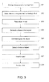
- FIG. 5 another aspect of the present disclosure provides a method for inspection of an object using RUS wherein the device may be easily reconfigured.
- the method of the present disclosure includes arranging a drive transducer and at least one receiving transducer in a rheological fluid 201. A magnetic or electric field is applied to the rheological fluid to "lock" the transducers in place 202. The object is then placed in the nest 203, the nest comprising the arrangement of transducers and support pins. Once the object has been placed, an ultrasound test signal is generated 204 and emitted onto the object 205. The vibration of the object is then measured using a receiving transducer 206, the signal from the receiving transducer being amplified 207 and sent to a computer for analyzing 208.
- the arrangement of the transducers may be optimized for the object to be tested.
- the arrangement for a particular object may also include one or more support pins, which for purposes of this disclosure necessarily includes other support objects that may not resemble pins.
- a robotic tool may be used to place the transducers and/or support pins.
- the robotic tool can place the transducers and/or support pins according detailed coordinates supplying information regarding placement and orientation.
- the robotic tool may be used to place the object to be tested in the nest.
- the robotic tool may include several appendages for arranging multiple pieces simultaneously.
Landscapes
- Physics & Mathematics (AREA)
- Health & Medical Sciences (AREA)
- Life Sciences & Earth Sciences (AREA)
- Chemical & Material Sciences (AREA)
- Analytical Chemistry (AREA)
- Biochemistry (AREA)
- General Health & Medical Sciences (AREA)
- General Physics & Mathematics (AREA)
- Immunology (AREA)
- Pathology (AREA)
- Acoustics & Sound (AREA)
- Investigating Or Analyzing Materials By The Use Of Ultrasonic Waves (AREA)
Applications Claiming Priority (1)
| Application Number | Priority Date | Filing Date | Title |
|---|---|---|---|
| US12/392,702 US8051715B2 (en) | 2009-02-25 | 2009-02-25 | Resonant inspection using reconfigurable nest |
Publications (3)
| Publication Number | Publication Date |
|---|---|
| EP2224237A2 true EP2224237A2 (de) | 2010-09-01 |
| EP2224237A3 EP2224237A3 (de) | 2011-07-13 |
| EP2224237B1 EP2224237B1 (de) | 2012-10-10 |
Family
ID=42244750
Family Applications (1)
| Application Number | Title | Priority Date | Filing Date |
|---|---|---|---|
| EP10154417A Not-in-force EP2224237B1 (de) | 2009-02-25 | 2010-02-23 | Resonanzprüfung mit rekonfigurierbarem Nest |
Country Status (2)
| Country | Link |
|---|---|
| US (1) | US8051715B2 (de) |
| EP (1) | EP2224237B1 (de) |
Cited By (1)
| Publication number | Priority date | Publication date | Assignee | Title |
|---|---|---|---|---|
| WO2018069016A1 (fr) * | 2016-10-13 | 2018-04-19 | Universite Pierre Et Marie Curie (Paris 6) | Transducteur piezoelectrique, procede de fabrication s'y rapportant, et dispositif de spectroscopie par resonance ultrasonore |
Families Citing this family (3)
| Publication number | Priority date | Publication date | Assignee | Title |
|---|---|---|---|---|
| US11215566B2 (en) | 2016-07-14 | 2022-01-04 | The Boeing Company | System and method for internally inspecting a tubular composite part |
| CN107219303B (zh) * | 2017-07-20 | 2023-06-27 | 北京化工大学 | 一种磁流体密封局部水浸式超声检测仪及其检测方法 |
| CN111811708A (zh) | 2020-07-23 | 2020-10-23 | 北京理工大学 | 一种基于磁流体耦合的机械构件超声测试装置和测试方法 |
Citations (3)
| Publication number | Priority date | Publication date | Assignee | Title |
|---|---|---|---|---|
| US5062296A (en) | 1990-09-20 | 1991-11-05 | The United States Of America As Represented By The Department Of Energy | Resonant ultrasound spectroscopy |
| US5631423A (en) | 1995-03-25 | 1997-05-20 | Quatro Corporation | Method for resonant measurement |
| US20010050454A1 (en) | 2000-02-18 | 2001-12-13 | Xuesong Zhang | Holding apparatus and method utilizing magnetorheological material |
Family Cites Families (10)
| Publication number | Priority date | Publication date | Assignee | Title |
|---|---|---|---|---|
| US3662589A (en) * | 1971-02-02 | 1972-05-16 | Atomic Energy Commission | Ultrasonic flaw determination by spectral analysis |
| FR2429430A1 (fr) * | 1978-06-21 | 1980-01-18 | Anvar | Procede et appareil destines a l'evaluation de fissures, en particulier a la mesure de leur longueur |
| US5228004A (en) * | 1988-12-21 | 1993-07-13 | Ngk Insulators, Ltd. | Ultrasonic testing method |
| US5351543A (en) * | 1991-12-27 | 1994-10-04 | The Regents Of The University Of California, Office Of Technology Transfer | Crack detection using resonant ultrasound spectroscopy |
| US5355731A (en) * | 1992-05-08 | 1994-10-18 | The Regents Of The University Of California, Office Of Technology Transfer | Sphericity determination using resonant ultrasound spectroscopy |
| US5490436A (en) * | 1994-03-17 | 1996-02-13 | At&T Corp. | Liquid-chamber apparatus for active, dynamic balancing of rotating machinery |
| US5837896A (en) * | 1995-08-23 | 1998-11-17 | Quasar International | Detection of defects using resonant ultrasound spectroscopy at predicted high order modes |
| US6330827B1 (en) * | 1998-12-04 | 2001-12-18 | The Regents Of The University Of California | Resonant nonlinear ultrasound spectroscopy |
| DE10108065B4 (de) * | 2001-02-20 | 2005-09-15 | Siemens Ag | Computertomograph |
| DE10320973B4 (de) * | 2003-05-09 | 2006-04-27 | Siemens Ag | Bildgebendes Tomographie-Gerät und Verfahren zur Verminderung einer Unwucht an einem Tomographie-Gerät |
-
2009
- 2009-02-25 US US12/392,702 patent/US8051715B2/en not_active Expired - Fee Related
-
2010
- 2010-02-23 EP EP10154417A patent/EP2224237B1/de not_active Not-in-force
Patent Citations (3)
| Publication number | Priority date | Publication date | Assignee | Title |
|---|---|---|---|---|
| US5062296A (en) | 1990-09-20 | 1991-11-05 | The United States Of America As Represented By The Department Of Energy | Resonant ultrasound spectroscopy |
| US5631423A (en) | 1995-03-25 | 1997-05-20 | Quatro Corporation | Method for resonant measurement |
| US20010050454A1 (en) | 2000-02-18 | 2001-12-13 | Xuesong Zhang | Holding apparatus and method utilizing magnetorheological material |
Cited By (3)
| Publication number | Priority date | Publication date | Assignee | Title |
|---|---|---|---|---|
| WO2018069016A1 (fr) * | 2016-10-13 | 2018-04-19 | Universite Pierre Et Marie Curie (Paris 6) | Transducteur piezoelectrique, procede de fabrication s'y rapportant, et dispositif de spectroscopie par resonance ultrasonore |
| FR3057667A1 (fr) * | 2016-10-13 | 2018-04-20 | Universite Pierre Et Marie Curie (Paris 6) | Transducteur piezoelectrique, procede de fabrication s'y rapportant, et dispositif de spectroscopie par resonance ultrasonore |
| US10859537B2 (en) | 2016-10-13 | 2020-12-08 | Sorbonne Universite | Piezoelectric transducer, manufacturing process pertaining thereto, and resonant ultrasound spectroscopy device |
Also Published As
| Publication number | Publication date |
|---|---|
| US20100212427A1 (en) | 2010-08-26 |
| US8051715B2 (en) | 2011-11-08 |
| EP2224237A3 (de) | 2011-07-13 |
| EP2224237B1 (de) | 2012-10-10 |
Similar Documents
| Publication | Publication Date | Title |
|---|---|---|
| US11056731B2 (en) | Modular, adaptable holders for sensors and battery cells for physical analysis | |
| EP2661329B1 (de) | Verbesserungen an oder im zusammenhang mit einer ultraschallerzeugungsvorrichtung und verfahren zur ultraschallerzeugung | |
| US7373260B2 (en) | Sensor infrastructure | |
| US8185327B2 (en) | Monitoring of composite materials | |
| US8051715B2 (en) | Resonant inspection using reconfigurable nest | |
| US4188830A (en) | Apparatus for examining structures using stimulated acoustic emission | |
| EP3722802B1 (de) | Multifunktionales ultraschall-phasenarray-bildgebungsgerät | |
| CN105424798A (zh) | 一种主动检测金属薄壁结构件中缺陷的方法 | |
| US7533578B2 (en) | Triangulation with co-located sensors | |
| CN105188337A (zh) | 颗粒噪声检测夹具、装置及方法 | |
| CN111678993B (zh) | 无损检测系统以及方法 | |
| US11883844B2 (en) | Multi-frequency wireless sensor | |
| CN106442734B (zh) | 一种小型不规则铸件声谱无损检测装置及检测方法 | |
| WO2018072042A1 (en) | Method and device for compensating for coupling nonuniformities in ultrasonic testing | |
| US5642331A (en) | Constant radius acoustic sensor mounting system | |
| CN104807890A (zh) | 利用声学频谱分析鉴定异形零部件连续性的装置及方法 | |
| Frankenstein et al. | Monitoring Network for SHM in avionic applications | |
| CN109239205A (zh) | 电磁超声传感器控制设备、方法以及装置 | |
| US20120089345A1 (en) | Method for measuring the compressibility and resonant frequency of disc brake pads | |
| CN121678830A (zh) | 一种超声波检测装置 | |
| KR20230027599A (ko) | 전자부품의 결함 검출장치 및 검출방법 | |
| US20160341703A1 (en) | Ultrasonic test apparatus and method for ultrasonic testing | |
| NO312527B1 (no) | Fremgangsmåte og utstyr for testing av legemer |
Legal Events
| Date | Code | Title | Description |
|---|---|---|---|
| PUAI | Public reference made under article 153(3) epc to a published international application that has entered the european phase |
Free format text: ORIGINAL CODE: 0009012 |
|
| 17P | Request for examination filed |
Effective date: 20100224 |
|
| AK | Designated contracting states |
Kind code of ref document: A2 Designated state(s): AT BE BG CH CY CZ DE DK EE ES FI FR GB GR HR HU IE IS IT LI LT LU LV MC MK MT NL NO PL PT RO SE SI SK SM TR |
|
| AX | Request for extension of the european patent |
Extension state: AL BA RS |
|
| PUAL | Search report despatched |
Free format text: ORIGINAL CODE: 0009013 |
|
| AK | Designated contracting states |
Kind code of ref document: A3 Designated state(s): AT BE BG CH CY CZ DE DK EE ES FI FR GB GR HR HU IE IS IT LI LT LU LV MC MK MT NL NO PL PT RO SE SI SK SM TR |
|
| AX | Request for extension of the european patent |
Extension state: AL BA RS |
|
| GRAP | Despatch of communication of intention to grant a patent |
Free format text: ORIGINAL CODE: EPIDOSNIGR1 |
|
| GRAS | Grant fee paid |
Free format text: ORIGINAL CODE: EPIDOSNIGR3 |
|
| GRAA | (expected) grant |
Free format text: ORIGINAL CODE: 0009210 |
|
| AK | Designated contracting states |
Kind code of ref document: B1 Designated state(s): AT BE BG CH CY CZ DE DK EE ES FI FR GB GR HR HU IE IS IT LI LT LU LV MC MK MT NL NO PL PT RO SE SI SK SM TR |
|
| REG | Reference to a national code |
Ref country code: GB Ref legal event code: FG4D |
|
| REG | Reference to a national code |
Ref country code: AT Ref legal event code: REF Ref document number: 579180 Country of ref document: AT Kind code of ref document: T Effective date: 20121015 Ref country code: CH Ref legal event code: EP |
|
| REG | Reference to a national code |
Ref country code: IE Ref legal event code: FG4D |
|
| REG | Reference to a national code |
Ref country code: DE Ref legal event code: R096 Ref document number: 602010003107 Country of ref document: DE Effective date: 20121206 |
|
| PG25 | Lapsed in a contracting state [announced via postgrant information from national office to epo] |
Ref country code: SI Free format text: LAPSE BECAUSE OF FAILURE TO SUBMIT A TRANSLATION OF THE DESCRIPTION OR TO PAY THE FEE WITHIN THE PRESCRIBED TIME-LIMIT Effective date: 20121010 |
|
| REG | Reference to a national code |
Ref country code: NL Ref legal event code: VDEP Effective date: 20121010 |
|
| REG | Reference to a national code |
Ref country code: AT Ref legal event code: MK05 Ref document number: 579180 Country of ref document: AT Kind code of ref document: T Effective date: 20121010 |
|
| REG | Reference to a national code |
Ref country code: LT Ref legal event code: MG4D |
|
| PG25 | Lapsed in a contracting state [announced via postgrant information from national office to epo] |
Ref country code: LT Free format text: LAPSE BECAUSE OF FAILURE TO SUBMIT A TRANSLATION OF THE DESCRIPTION OR TO PAY THE FEE WITHIN THE PRESCRIBED TIME-LIMIT Effective date: 20121010 Ref country code: HR Free format text: LAPSE BECAUSE OF FAILURE TO SUBMIT A TRANSLATION OF THE DESCRIPTION OR TO PAY THE FEE WITHIN THE PRESCRIBED TIME-LIMIT Effective date: 20121010 Ref country code: NL Free format text: LAPSE BECAUSE OF FAILURE TO SUBMIT A TRANSLATION OF THE DESCRIPTION OR TO PAY THE FEE WITHIN THE PRESCRIBED TIME-LIMIT Effective date: 20121010 Ref country code: IS Free format text: LAPSE BECAUSE OF FAILURE TO SUBMIT A TRANSLATION OF THE DESCRIPTION OR TO PAY THE FEE WITHIN THE PRESCRIBED TIME-LIMIT Effective date: 20130210 Ref country code: NO Free format text: LAPSE BECAUSE OF FAILURE TO SUBMIT A TRANSLATION OF THE DESCRIPTION OR TO PAY THE FEE WITHIN THE PRESCRIBED TIME-LIMIT Effective date: 20130110 Ref country code: SE Free format text: LAPSE BECAUSE OF FAILURE TO SUBMIT A TRANSLATION OF THE DESCRIPTION OR TO PAY THE FEE WITHIN THE PRESCRIBED TIME-LIMIT Effective date: 20121010 Ref country code: ES Free format text: LAPSE BECAUSE OF FAILURE TO SUBMIT A TRANSLATION OF THE DESCRIPTION OR TO PAY THE FEE WITHIN THE PRESCRIBED TIME-LIMIT Effective date: 20130121 Ref country code: FI Free format text: LAPSE BECAUSE OF FAILURE TO SUBMIT A TRANSLATION OF THE DESCRIPTION OR TO PAY THE FEE WITHIN THE PRESCRIBED TIME-LIMIT Effective date: 20121010 |
|
| PG25 | Lapsed in a contracting state [announced via postgrant information from national office to epo] |
Ref country code: PL Free format text: LAPSE BECAUSE OF FAILURE TO SUBMIT A TRANSLATION OF THE DESCRIPTION OR TO PAY THE FEE WITHIN THE PRESCRIBED TIME-LIMIT Effective date: 20121010 Ref country code: GR Free format text: LAPSE BECAUSE OF FAILURE TO SUBMIT A TRANSLATION OF THE DESCRIPTION OR TO PAY THE FEE WITHIN THE PRESCRIBED TIME-LIMIT Effective date: 20130111 Ref country code: LV Free format text: LAPSE BECAUSE OF FAILURE TO SUBMIT A TRANSLATION OF THE DESCRIPTION OR TO PAY THE FEE WITHIN THE PRESCRIBED TIME-LIMIT Effective date: 20121010 Ref country code: PT Free format text: LAPSE BECAUSE OF FAILURE TO SUBMIT A TRANSLATION OF THE DESCRIPTION OR TO PAY THE FEE WITHIN THE PRESCRIBED TIME-LIMIT Effective date: 20130211 Ref country code: BE Free format text: LAPSE BECAUSE OF FAILURE TO SUBMIT A TRANSLATION OF THE DESCRIPTION OR TO PAY THE FEE WITHIN THE PRESCRIBED TIME-LIMIT Effective date: 20121010 |
|
| PG25 | Lapsed in a contracting state [announced via postgrant information from national office to epo] |
Ref country code: AT Free format text: LAPSE BECAUSE OF FAILURE TO SUBMIT A TRANSLATION OF THE DESCRIPTION OR TO PAY THE FEE WITHIN THE PRESCRIBED TIME-LIMIT Effective date: 20121010 |
|
| PG25 | Lapsed in a contracting state [announced via postgrant information from national office to epo] |
Ref country code: EE Free format text: LAPSE BECAUSE OF FAILURE TO SUBMIT A TRANSLATION OF THE DESCRIPTION OR TO PAY THE FEE WITHIN THE PRESCRIBED TIME-LIMIT Effective date: 20121010 Ref country code: DK Free format text: LAPSE BECAUSE OF FAILURE TO SUBMIT A TRANSLATION OF THE DESCRIPTION OR TO PAY THE FEE WITHIN THE PRESCRIBED TIME-LIMIT Effective date: 20121010 Ref country code: CZ Free format text: LAPSE BECAUSE OF FAILURE TO SUBMIT A TRANSLATION OF THE DESCRIPTION OR TO PAY THE FEE WITHIN THE PRESCRIBED TIME-LIMIT Effective date: 20121010 Ref country code: BG Free format text: LAPSE BECAUSE OF FAILURE TO SUBMIT A TRANSLATION OF THE DESCRIPTION OR TO PAY THE FEE WITHIN THE PRESCRIBED TIME-LIMIT Effective date: 20130110 Ref country code: SK Free format text: LAPSE BECAUSE OF FAILURE TO SUBMIT A TRANSLATION OF THE DESCRIPTION OR TO PAY THE FEE WITHIN THE PRESCRIBED TIME-LIMIT Effective date: 20121010 |
|
| PLBE | No opposition filed within time limit |
Free format text: ORIGINAL CODE: 0009261 |
|
| STAA | Information on the status of an ep patent application or granted ep patent |
Free format text: STATUS: NO OPPOSITION FILED WITHIN TIME LIMIT |
|
| PG25 | Lapsed in a contracting state [announced via postgrant information from national office to epo] |
Ref country code: IT Free format text: LAPSE BECAUSE OF FAILURE TO SUBMIT A TRANSLATION OF THE DESCRIPTION OR TO PAY THE FEE WITHIN THE PRESCRIBED TIME-LIMIT Effective date: 20121010 Ref country code: RO Free format text: LAPSE BECAUSE OF FAILURE TO SUBMIT A TRANSLATION OF THE DESCRIPTION OR TO PAY THE FEE WITHIN THE PRESCRIBED TIME-LIMIT Effective date: 20121010 |
|
| 26N | No opposition filed |
Effective date: 20130711 |
|
| PG25 | Lapsed in a contracting state [announced via postgrant information from national office to epo] |
Ref country code: MC Free format text: LAPSE BECAUSE OF NON-PAYMENT OF DUE FEES Effective date: 20130228 |
|
| REG | Reference to a national code |
Ref country code: DE Ref legal event code: R097 Ref document number: 602010003107 Country of ref document: DE Effective date: 20130711 |
|
| PG25 | Lapsed in a contracting state [announced via postgrant information from national office to epo] |
Ref country code: CY Free format text: LAPSE BECAUSE OF FAILURE TO SUBMIT A TRANSLATION OF THE DESCRIPTION OR TO PAY THE FEE WITHIN THE PRESCRIBED TIME-LIMIT Effective date: 20121010 |
|
| REG | Reference to a national code |
Ref country code: IE Ref legal event code: MM4A |
|
| REG | Reference to a national code |
Ref country code: IE Ref legal event code: NE4A |
|
| PG25 | Lapsed in a contracting state [announced via postgrant information from national office to epo] |
Ref country code: IE Free format text: LAPSE BECAUSE OF NON-PAYMENT OF DUE FEES Effective date: 20130223 |
|
| PG25 | Lapsed in a contracting state [announced via postgrant information from national office to epo] |
Ref country code: MT Free format text: LAPSE BECAUSE OF FAILURE TO SUBMIT A TRANSLATION OF THE DESCRIPTION OR TO PAY THE FEE WITHIN THE PRESCRIBED TIME-LIMIT Effective date: 20121010 |
|
| REG | Reference to a national code |
Ref country code: CH Ref legal event code: PL |
|
| PG25 | Lapsed in a contracting state [announced via postgrant information from national office to epo] |
Ref country code: LI Free format text: LAPSE BECAUSE OF NON-PAYMENT OF DUE FEES Effective date: 20140228 Ref country code: CH Free format text: LAPSE BECAUSE OF NON-PAYMENT OF DUE FEES Effective date: 20140228 |
|
| PG25 | Lapsed in a contracting state [announced via postgrant information from national office to epo] |
Ref country code: SM Free format text: LAPSE BECAUSE OF FAILURE TO SUBMIT A TRANSLATION OF THE DESCRIPTION OR TO PAY THE FEE WITHIN THE PRESCRIBED TIME-LIMIT Effective date: 20121010 |
|
| PG25 | Lapsed in a contracting state [announced via postgrant information from national office to epo] |
Ref country code: TR Free format text: LAPSE BECAUSE OF FAILURE TO SUBMIT A TRANSLATION OF THE DESCRIPTION OR TO PAY THE FEE WITHIN THE PRESCRIBED TIME-LIMIT Effective date: 20121010 |
|
| PG25 | Lapsed in a contracting state [announced via postgrant information from national office to epo] |
Ref country code: LU Free format text: LAPSE BECAUSE OF NON-PAYMENT OF DUE FEES Effective date: 20130223 Ref country code: MK Free format text: LAPSE BECAUSE OF FAILURE TO SUBMIT A TRANSLATION OF THE DESCRIPTION OR TO PAY THE FEE WITHIN THE PRESCRIBED TIME-LIMIT Effective date: 20121010 Ref country code: HU Free format text: LAPSE BECAUSE OF FAILURE TO SUBMIT A TRANSLATION OF THE DESCRIPTION OR TO PAY THE FEE WITHIN THE PRESCRIBED TIME-LIMIT; INVALID AB INITIO Effective date: 20100223 |
|
| REG | Reference to a national code |
Ref country code: FR Ref legal event code: PLFP Year of fee payment: 7 |
|
| REG | Reference to a national code |
Ref country code: FR Ref legal event code: PLFP Year of fee payment: 8 |
|
| REG | Reference to a national code |
Ref country code: FR Ref legal event code: PLFP Year of fee payment: 9 |
|
| PGFP | Annual fee paid to national office [announced via postgrant information from national office to epo] |
Ref country code: GB Payment date: 20220225 Year of fee payment: 13 Ref country code: DE Payment date: 20220225 Year of fee payment: 13 |
|
| PGFP | Annual fee paid to national office [announced via postgrant information from national office to epo] |
Ref country code: FR Payment date: 20220223 Year of fee payment: 13 |
|
| REG | Reference to a national code |
Ref country code: DE Ref legal event code: R119 Ref document number: 602010003107 Country of ref document: DE |
|
| GBPC | Gb: european patent ceased through non-payment of renewal fee |
Effective date: 20230223 |
|
| PG25 | Lapsed in a contracting state [announced via postgrant information from national office to epo] |
Ref country code: GB Free format text: LAPSE BECAUSE OF NON-PAYMENT OF DUE FEES Effective date: 20230223 |
|
| PG25 | Lapsed in a contracting state [announced via postgrant information from national office to epo] |
Ref country code: GB Free format text: LAPSE BECAUSE OF NON-PAYMENT OF DUE FEES Effective date: 20230223 Ref country code: FR Free format text: LAPSE BECAUSE OF NON-PAYMENT OF DUE FEES Effective date: 20230228 Ref country code: DE Free format text: LAPSE BECAUSE OF NON-PAYMENT OF DUE FEES Effective date: 20230901 |