EP2224150A1 - Dispositif de tension de courroie et appareil de numérisation comportant un tel dispositif - Google Patents
Dispositif de tension de courroie et appareil de numérisation comportant un tel dispositif Download PDFInfo
- Publication number
- EP2224150A1 EP2224150A1 EP10154831A EP10154831A EP2224150A1 EP 2224150 A1 EP2224150 A1 EP 2224150A1 EP 10154831 A EP10154831 A EP 10154831A EP 10154831 A EP10154831 A EP 10154831A EP 2224150 A1 EP2224150 A1 EP 2224150A1
- Authority
- EP
- European Patent Office
- Prior art keywords
- pulley
- belt
- frame
- axis
- parallel
- Prior art date
- Legal status (The legal status is an assumption and is not a legal conclusion. Google has not performed a legal analysis and makes no representation as to the accuracy of the status listed.)
- Granted
Links
Images

Classifications
-
- H—ELECTRICITY
- H04—ELECTRIC COMMUNICATION TECHNIQUE
- H04N—PICTORIAL COMMUNICATION, e.g. TELEVISION
- H04N1/00—Scanning, transmission or reproduction of documents or the like, e.g. facsimile transmission; Details thereof
- H04N1/04—Scanning arrangements, i.e. arrangements for the displacement of active reading or reproducing elements relative to the original or reproducing medium, or vice versa
- H04N1/10—Scanning arrangements, i.e. arrangements for the displacement of active reading or reproducing elements relative to the original or reproducing medium, or vice versa using flat picture-bearing surfaces
- H04N1/1013—Scanning arrangements, i.e. arrangements for the displacement of active reading or reproducing elements relative to the original or reproducing medium, or vice versa using flat picture-bearing surfaces with sub-scanning by translatory movement of at least a part of the main-scanning components
- H04N1/1017—Scanning arrangements, i.e. arrangements for the displacement of active reading or reproducing elements relative to the original or reproducing medium, or vice versa using flat picture-bearing surfaces with sub-scanning by translatory movement of at least a part of the main-scanning components the main-scanning components remaining positionally invariant with respect to one another in the sub-scanning direction
-
- F—MECHANICAL ENGINEERING; LIGHTING; HEATING; WEAPONS; BLASTING
- F16—ENGINEERING ELEMENTS AND UNITS; GENERAL MEASURES FOR PRODUCING AND MAINTAINING EFFECTIVE FUNCTIONING OF MACHINES OR INSTALLATIONS; THERMAL INSULATION IN GENERAL
- F16H—GEARING
- F16H7/00—Gearings for conveying rotary motion by endless flexible members
- F16H7/08—Means for varying tension of belts, ropes or chains
- F16H7/10—Means for varying tension of belts, ropes or chains by adjusting the axis of a pulley
- F16H7/12—Means for varying tension of belts, ropes or chains by adjusting the axis of a pulley of an idle pulley
- F16H7/1254—Means for varying tension of belts, ropes or chains by adjusting the axis of a pulley of an idle pulley without vibration damping means
- F16H7/1281—Means for varying tension of belts, ropes or chains by adjusting the axis of a pulley of an idle pulley without vibration damping means where the axis of the pulley moves along a substantially circular path
-
- H—ELECTRICITY
- H04—ELECTRIC COMMUNICATION TECHNIQUE
- H04N—PICTORIAL COMMUNICATION, e.g. TELEVISION
- H04N1/00—Scanning, transmission or reproduction of documents or the like, e.g. facsimile transmission; Details thereof
- H04N1/00567—Handling of original or reproduction media, e.g. cutting, separating, stacking
- H04N1/0062—Removing sheets from a stack or inputting media
-
- F—MECHANICAL ENGINEERING; LIGHTING; HEATING; WEAPONS; BLASTING
- F16—ENGINEERING ELEMENTS AND UNITS; GENERAL MEASURES FOR PRODUCING AND MAINTAINING EFFECTIVE FUNCTIONING OF MACHINES OR INSTALLATIONS; THERMAL INSULATION IN GENERAL
- F16H—GEARING
- F16H7/00—Gearings for conveying rotary motion by endless flexible members
- F16H7/08—Means for varying tension of belts, ropes or chains
- F16H2007/0802—Actuators for final output members
- F16H2007/0808—Extension coil springs
-
- F—MECHANICAL ENGINEERING; LIGHTING; HEATING; WEAPONS; BLASTING
- F16—ENGINEERING ELEMENTS AND UNITS; GENERAL MEASURES FOR PRODUCING AND MAINTAINING EFFECTIVE FUNCTIONING OF MACHINES OR INSTALLATIONS; THERMAL INSULATION IN GENERAL
- F16H—GEARING
- F16H7/00—Gearings for conveying rotary motion by endless flexible members
- F16H7/08—Means for varying tension of belts, ropes or chains
- F16H2007/0863—Finally actuated members, e.g. constructional details thereof
- F16H2007/0865—Pulleys
-
- F—MECHANICAL ENGINEERING; LIGHTING; HEATING; WEAPONS; BLASTING
- F16—ENGINEERING ELEMENTS AND UNITS; GENERAL MEASURES FOR PRODUCING AND MAINTAINING EFFECTIVE FUNCTIONING OF MACHINES OR INSTALLATIONS; THERMAL INSULATION IN GENERAL
- F16H—GEARING
- F16H7/00—Gearings for conveying rotary motion by endless flexible members
- F16H7/08—Means for varying tension of belts, ropes or chains
- F16H2007/0889—Path of movement of the finally actuated member
- F16H2007/0893—Circular path
-
- H—ELECTRICITY
- H04—ELECTRIC COMMUNICATION TECHNIQUE
- H04N—PICTORIAL COMMUNICATION, e.g. TELEVISION
- H04N1/00—Scanning, transmission or reproduction of documents or the like, e.g. facsimile transmission; Details thereof
- H04N1/04—Scanning arrangements, i.e. arrangements for the displacement of active reading or reproducing elements relative to the original or reproducing medium, or vice versa
- H04N1/19—Scanning arrangements, i.e. arrangements for the displacement of active reading or reproducing elements relative to the original or reproducing medium, or vice versa using multi-element arrays
- H04N1/191—Scanning arrangements, i.e. arrangements for the displacement of active reading or reproducing elements relative to the original or reproducing medium, or vice versa using multi-element arrays the array comprising a one-dimensional [1D] array
- H04N1/192—Simultaneously or substantially simultaneously scanning picture elements on one main scanning line
- H04N1/193—Simultaneously or substantially simultaneously scanning picture elements on one main scanning line using electrically scanned linear arrays, e.g. linear CCD arrays
Definitions
- the invention relates to a belt tensioning device and a flat document scanning apparatus (this type of apparatus is commonly referred to as "flat-bed").
- a flatbed scanning apparatus generally includes a frame, a scanning module mounted on the frame for sliding between two extreme positions along a scanning direction, and scanning means for moving the scanning module.
- the moving means comprises a belt wrapped around a driving pulley and a driven pulley which are mounted on the frame such that the belt extends parallel to the scanning direction.
- the scanning module is coupled to one of the strands of the belt. The regularity and precision of the scanning module's displacement contribute to the quality of the digitization.
- the apparatus comprises for this purpose a tensioning device allowing an optimum tension of the driven pulley via a spring mounted between a portion of the frame and the support thereof.
- a tension device comprising a slide which supports the driven pulley and which is slidably received between slides generally formed by portions of the frame.
- the spring is a helical compression spring which is mounted between the slider and a stop portion of the frame.
- the spring and the slider extend under the belt and parallel to it.
- the longitudinal and vertical encumbrance of the device limits the stroke of the scanning module that can not pass over the tensioning device.
- the slides are generally constituted by the edges of an opening in the frame so that the area in which the scanning module moves is not dustproof.
- Another tension device structure includes a lever having one end carrying the driven pulley and an opposite end mounted for pivoting on the frame.
- a torsion spring is mounted between the lever and the frame to bias the lever into an optimum tension position of the belt.
- Devices of this type are less bulky than devices of the previous type.
- the realization of a torsion spring having precise and reproducible stress characteristics proves delicate for the mass production whereas these characteristics condition the obtaining of the desired tension.
- Devices of the known type also have the disadvantage of having to be made of several pieces of different materials. The parts are assembled to each other and their disassembly requires tools. This complicates recycling and maintenance operations.
- a belt tensioning device comprising a rocker arm which is provided with a pivot axis and which comprises on either side of this axis: a portion associated with a helical spring mounted parallel to a pivoting plane of the rocker arm about its axis and a clevis-shaped portion for receiving a guide pulley of the belt, the pulley being secured to a pulley axis which is parallel to the rocker arm pivot axis and has ends received in notches in the yoke such that a parallel force on the pulley at a tension direction of the belt hold the ends of the axis against a bottom of the notches.
- the spring is shifted laterally relative to the belt and only the portion of the rocker arm extends under the belt freeing up space.
- the pulley and the rocker are assembled without tools, the pulley being held in position by the tension of the belt, and can be made of the same material.
- the pulley must have flanks to ensure the lateral retention of the belt on the pulley.
- the manufacture of the injection pulley requires the use of a mold with moving cores causing burrs on the range of the pulley. These burrs can affect the regularity of linear displacement of the optical module and alter the video quality during the analysis of the document.
- the yoke comprises facing inner faces spaced from each other by a distance slightly greater than a width of the pulley to form lateral holding means of the belt on the pulley.
- the pulley may be devoid of side holding flanks of the belt, this function being provided by the faces of the yoke.
- the invention also relates to a flat document scanning apparatus, comprising a frame, a scanning module mounted on the frame for sliding between two extreme positions along a scanning direction, and module moving means.
- scanner comprising a belt to which the scanning module is coupled and which is wrapped around a driving pulley and a driven pulley.
- the apparatus comprises a device of the aforementioned type whose rocker arm is mounted to pivot on one side of the frame and the pulley is the driven pulley.
- the digitizing apparatus described herein comprises a parallelepiped-shaped frame 1 having a bottom 2 surrounded by lateral walls 3 intended to support a document support window 4.
- a cover is intended to be articulated to one of the side walls 3 of the frame 1 to press the thin documents against the window 4.
- the cover can further integrate a sheet loader to be digitized.
- a scanning module 5 is mounted between the bottom 2 and the window 4 to move parallel to the window 4 along a scanning direction D.
- the scanning module 5 is slidably mounted on a slide 6 extending in parallel. to Directorate D.
- a driving pulley 7 connected to a drive motor by a gear train and a driven pulley 8 are mounted to pivot on the bottom 2.
- a belt 9 extends around the driving pulley 7 and the driven pulley 8 of such that the belt 9 extends parallel to the direction D.
- One of the strands of the belt 9 is attached to the scanning module 5.
- the motor is connected to a not shown control unit to move the scanning module 5 according to a reciprocating rectilinear motion between two extreme positions in which the digitizing module 5 extends adjacent two of the side walls 3, opposite to each other.
- the motor assembly of the driving pulley 7, its mounting on the frame 1 and its control mode are known in themselves and are therefore not more detailed here.
- the driven pulley 8 comprises a body 8.1 having a cylindrical outer surface forming a bearing for the belt 9 and two axis portions 8.2 extending axially from the body 8.1 coaxially to the cylindrical outer surface.
- the driven pulley 8 is secured to a tensioning device 10 of the belt 9.
- the tensioning device 10 comprises a rocker, generally designated 11, mounted on the bottom 2 by an axis 12 to pivot in a plane parallel to the window 4.
- the axis 12 is here a screw engaged perpendicularly in the bottom 2.
- the rocker 11 comprises on either side of the axis 12 an end portion forming a yoke 13 and an end portion forming an operating portion 14.
- the yoke 13 receives the driven pulley 8 to pivot.
- the yoke 13 comprises two walls 13.1, 13.2, parallel, having internal faces spaced from each other by a distance slightly greater than the width of the body 8.1 and each provided with a notch 15 receiving a portions of axis 8.2.
- the clevis 13 forms thus a support means for pivoting the pulley 8 and a lateral holding means of the belt 9 on the pulley 8.
- the operating portion 14 is connected to an end of a spring 16, helical and traction, of which an opposite end is attached to the frame 1.
- the rocker 11 extends in a direction substantially perpendicular to the belt 9 and parallel to the side wall 3 adjacent.
- the spring 16 extends parallel to the belt 9 next to it and in the pivoting plane of the rocker arm 11.
- the yoke 13 has dimensions close to those of the pulley 8 parallel to the tension direction of the belt.
- the spring 16 tends to bring the driven pulley 8 of the adjacent side wall 3 exerting a tension force of the belt 9 in a direction substantially parallel to the belt 9.
- the notches 15 are oriented so that the belt 9 under tension exerts on the driven pulley 8 an effort tending to maintain the shaft portions 8.2 against the bottom of the notches 15.
- the scanning module extends above the rocker 11 in one of its extreme positions (see figure 3 ). This allows the device to be particularly compact while leaving the scanning module a sufficient run to browse documents in standard format (here type A4 or A3). This has the effect of allowing a compact design, which improves the size and has an ecological impact on the quantities of material used.
- the belt 9 can be disassembled without tools by pivoting the rocker arm 11 to reduce the tension of the belt 9 to slid out the axle portions 8.2 of the notches 15 and release the driven pulley 8 from the walls 13.1 , 13.2.
- the buckle of the belt 9 which was mounted on the driven pulley 8 can then be removed from the clevis 13.
- the assembly is performed by performing the reverse operations (see figure 4 ).
- the rocker 11 and the pulley 8 are preferably made of the same material to facilitate recycling.
- the belt comprises two parallel strands
- the belt may be wrapped around more than two pulleys for example three such that the belt forms a triangle.
- the axis 12 may be a portion of the frame 1 or any other element allowing the rocker arm 11 to pivot.
- the spring 16 may be a compression spring mounted between the operating portion 14 and the adjacent side wall 4, this solution having the disadvantage of slightly increase the size.
- the device can be a simple scanning device such as a scanner or a multifunction device also incorporating a printer, or even a photocopier ...
Landscapes
- Engineering & Computer Science (AREA)
- Multimedia (AREA)
- Signal Processing (AREA)
- General Engineering & Computer Science (AREA)
- Mechanical Engineering (AREA)
- Devices For Conveying Motion By Means Of Endless Flexible Members (AREA)
- Optical Systems Of Projection Type Copiers (AREA)
- Mechanical Pencils And Projecting And Retracting Systems Therefor, And Multi-System Writing Instruments (AREA)
- Yarns And Mechanical Finishing Of Yarns Or Ropes (AREA)
- Character Spaces And Line Spaces In Printers (AREA)
- Facsimile Scanning Arrangements (AREA)
Abstract
Description
- L'invention concerne un dispositif de tension de courroie et un appareil de numérisation à plat de document (ce type d'appareil est couramment désigné par la dénomination anglaise « flat-bed »).
- Un appareil de numérisation à plat comporte généralement un bâti, un module de numérisation monté sur le bâti pour coulisser entre deux positions extrêmes le long d'une direction de numérisation, et des moyens de déplacement du module de numérisation. Les moyens de déplacement comportent une courroie enroulée autour d'une poulie motrice et d'une poulie menée qui sont montées sur le bâti de telle manière que la courroie s'étende parallèlement à la direction de numérisation. Le module de numérisation est attelé à un des brins de la courroie. La régularité et la précision du déplacement du module de numérisation participent à la qualité de la numérisation. L'appareil comprend à cette fin un dispositif de tension permettant une tension optimale de la poulie menée via un ressort monté entre une portion du bâti et le support de cette dernière.
- Il est connu un dispositif de tension comportant un coulisseau qui supporte la poulie menée et qui est reçu à coulissement entre des glissières généralement formées par des portions du bâti. Le ressort est un ressort hélicoïdal de compression qui est monté entre le coulisseau et une portion de butée du bâti. Le ressort et le coulisseau s'étendent sous la courroie et parallèlement à celle-ci. L'encombrement longitudinal et vertical du dispositif limite la course du module de numérisation qui ne peut pas passer au-dessus du dispositif de tension. En outre, les glissières sont généralement constituées par les bords d'une ouverture ménagée dans le bâti de sorte que la zone dans laquelle se déplace le module de numérisation n'est pas étanche à la poussière. Lorsque l'appareil de numérisation appartient à un ensemble multifonction incorporant également une imprimante, l'appareil de numérisation est monté sur l'imprimante qui comporte une source laser engendrant par convection des flux d'air qui risquent de transporter des poussières jusqu'au module de numérisation si des moyens d'étanchéité dédiés ne sont pas prévus.
- Une autre structure de dispositif de tension comprend un levier ayant une extrémité portant la poulie menée et une extrémité opposée montée pour pivoter sur le bâti. Un ressort de torsion est monté entre le levier et le bâti pour rappeler le levier dans une position de tension optimum de la courroie. Les dispositifs de ce type sont moins encombrants que les dispositifs du type précédent. En revanche, la réalisation d'un ressort de torsion ayant des caractéristiques d'effort précises et reproductibles se révèle délicate pour la fabrication de série alors que ces caractéristiques conditionnent l'obtention de la tension souhaitée.
- Les dispositifs du type connu présentent en outre l'inconvénient de devoir être constitués de plusieurs pièces de matériaux différents. Les pièces sont assemblées les unes aux autres et leur démontage nécessite des outils. Ceci complique le recyclage et les opérations de maintenance.
- Selon l'invention, on prévoit, un dispositif de tension de courroie comportant un culbuteur qui est pourvu d'un axe de pivotement et qui comporte de part et d'autre de cet axe : une portion associée à un ressort hélicoïdal monté parallèlement à un plan de pivotement du culbuteur autour de son axe et une portion en forme de chape pour recevoir une poulie de guidage de la courroie, la poulie étant solidaire d'un axe de poulie qui est parallèle à l'axe de pivotement du culbuteur et a des extrémités reçues dans des encoches ménagées dans la chape de telle manière qu'un effort sur la poulie parallèlement à une direction de tension de la courroie maintienne les extrémités de l'axe contre un fond des encoches.
- Ainsi, le ressort est décalé latéralement par rapport à la courroie et seule la portion du culbuteur formant chape s'étend sous la courroie libérant un maximum d'espace. La poulie et le culbuteur sont assemblés sans outil, la poulie étant maintenue en position par la tension de la courroie, et peuvent être fabriqués en un même matériau.
- Par ailleurs, dans les dispositifs connus la poulie doit comporter des flancs pour assurer le maintien latéral de la courroie sur la poulie. La fabrication de la poulie par injection nécessite d'utiliser un moule à noyaux mobiles occasionnant des bavures sur la portée de la poulie. Ces bavures peuvent affecter la régularité du déplacement linéaire du module optique et altérer la qualité video lors de l'analyse du document.
- De préférence, la chape comprend des faces internes en regard écartées l'une de l'autre d'une distance légèrement supérieure à une largeur de la poulie pour former des moyens de maintien latéral de la courroie sur la poulie.
- Ainsi, la poulie peut être dépourvue de flancs de maintien latéral de la courroie, cette fonction étant assurée par les faces de la chape.
- L'invention a également pour objet un appareil de numérisation à plat de documents, comportant un bâti, un module de numérisation monté sur le bâti pour coulisser entre deux positions extrêmes le long d'une direction de numérisation, et des moyens de déplacement du module de numérisation comportant une courroie à laquelle est attelé le module de numérisation et qui est enroulée autour d'une poulie motrice et d'une poulie menée. L'appareil comporte un dispositif du type précité dont le culbuteur est monté pour pivoter sur un côté du bâti et la poulie est la poulie menée.
- D'autres caractéristiques et avantages de l'invention ressortiront à la lecture de la description qui suit d'un mode de réalisation particulier non limitatif de l'invention.
- Il sera fait référence aux dessins annexés, parmi lesquels :
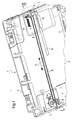
- la
figure 1 est une vue partielle en perspective d'un appareil de numérisation conforme à l'invention, - la
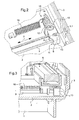
figure 2 est une vue agrandie en perspective de la zone II de lafigure 1 , - la
figure 3 est une vue partielle de l'appareil, en coupe selon le plan III de lafigure 1 , le module de numérisation étant dans sa position extrême au-dessus du dispositif de tension, - la
figure 4 est une vue analogue à lafigure 2 illustrant le montage de la poulie, - la
figure 5 est une vue en perspective du culbuteur du dispositif de tension conforme à l'invention. - En référence aux figures, l'appareil de numérisation ici décrit comprend un bâti 1 de forme parallélépipédique comportant un fond 2 ceint de parois latérales 3 destinées à supporter une vitre 4 support de document. Un capot, non visible sur les figures, est destiné à être articulé à une des parois latérales 3 du bâti 1 pour plaquer les documents peu épais contre la vitre 4. Le capot peu en outre intégrer un chargeur de feuilles à numériser.
- Un module de numérisation 5 est monté entre le fond 2 et la vitre 4 pour se déplacer parallèlement à la vitre 4 le long d'une direction de numérisation D. Le module de numérisation 5 est monté pour coulisser sur une glissière 6 s'étendant parallèlement à la direction D. Une poulie motrice 7 reliée à un moteur d'entraînement par un train d'engrenages et une poulie menée 8 sont montées pour pivoter sur le fond 2. Une courroie 9 s'étend autour de la poulie motrice 7 et de la poulie menée 8 de telle manière que la courroie 9 s'étende parallèlement à la direction D. Un des brins de la courroie 9 est attaché au module de numérisation 5. Le moteur est relié à une unité de commande non représentée pour déplacer le module de numérisation 5 selon un mouvement rectiligne alternatif entre deux positions extrêmes dans lesquelles le module de numérisation 5 s'étend au voisinage de deux des parois latérales 3, opposées l'une à l'autre. L'ensemble de motorisation de la poulie motrice 7, son montage sur le bâti 1 et son mode de commande sont connus en eux-mêmes et ne sont donc pas plus détaillés ici.
- La poulie menée 8 comprend un corps 8.1 ayant une surface extérieure cylindrique formant une portée pour la courroie 9 et deux portions d'axe 8.2 s'étendant en saillie axiale du corps 8.1 coaxialement à la surface extérieure cylindrique. La poulie menée 8 est solidaire d'un dispositif de tension 10 de la courroie 9.
- Le dispositif de tension 10 comprend un culbuteur, généralement désigné en 11, monté sur le fond 2 par un axe 12 pour pivoter dans un plan parallèle à la vitre 4. L'axe 12 est ici une vis engagée perpendiculairement dans le fond 2. Le culbuteur 11 comporte de part et d'autre de l'axe 12 une portion d'extrémité formant une chape 13 et une portion d'extrémité formant portion de manoeuvre 14.
- La chape 13 reçoit la poulie menée 8 à pivotement. A cette fin, la chape 13 comprend deux parois 13.1, 13.2, parallèles, ayant des faces internes espacées l'une de l'autre d'une distance légèrement supérieure à la largeur du corps 8.1 et pourvues chacune d'une encoche 15 recevant une des portions d'axe 8.2. La chape 13 forme ainsi un moyen de support à pivotement de la poulie 8 et un moyen de maintien latéral de la courroie 9 sur la poulie 8.
- La portion de manoeuvre 14 est reliée à une extrémité d'un ressort 16, hélicoïdal et de traction, dont une extrémité opposée est accrochée au bâti 1.
- Le culbuteur 11 s'étend selon une direction sensiblement perpendiculaire à la courroie 9 et parallèle à la paroi latérale 3 adjacente. Le ressort 16 s'étend parallèlement à la courroie 9 à côté de celle-ci et dans le plan de pivotement du culbuteur 11. La chape 13 a des dimensions voisines de celles de la poulie 8 parallèlement à la direction de tension de la courroie. Le ressort 16 tend à rapprocher la poulie menée 8 de la paroi latérale 3 adjacente exerçant un effort de tension de la courroie 9 selon une direction sensiblement parallèle à la courroie 9. Les encoches 15 sont orientées de telle manière que la courroie 9 sous tension exerce sur la poulie menée 8 un effort tendant à maintenir les portions d'arbre 8.2 contre le fond des encoches 15.
- On notera que le module de numérisation s'étend au-dessus du culbuteur 11 dans une de ses positions extrêmes (voir la
figure 3 ). Ceci permet à l'appareil d'être particulièrement compact tout en laissant au module de numérisation une course suffisante pour parcourir les documents de format standard (ici de type A4 ou A3). Ceci a pour effet de permettre une conception compacte, qui améliore l'encombrement et a un impact écologique sur les quantités de matière utilisées. - La courroie 9 peut être démontée sans outil en faisant pivoter le culbuteur 11 pour diminuer la tension de la courroie 9 jusqu'à faire sortir par coulissement les portions d'axe 8.2 des encoches 15 et dégager la poulie menée 8 d'entre les parois 13.1, 13.2. La boucle de la courroie 9 qui était montée sur la poulie menée 8 peut alors être sortie de la chape 13. Le montage est réalisé en effectuant les opérations inverses (voir la
figure 4 ). - Le culbuteur 11 et la poulie 8 sont de préférence réalisés dans le même matériau pour en faciliter le recyclage.
- Bien entendu, l'invention n'est pas limitée au mode de réalisation décrit mais englobe toutes les variantes entrant dans le champ de l'invention telle que définie par les revendications.
- En particulier, bien que dans le mode de réalisation décrit la courroie comprenne deux brins parallèles, la courroie peut être enroulée autour de plus de deux poulies par exemple trois de telle manière que la courroie forme un triangle.
- L'axe 12 peut être une portion du bâti 1 ou tout autre élément permettant le pivotement du culbuteur 11.
- Le ressort 16 peut être un ressort de compression monté entre la portion de manoeuvre 14 et la paroi latérale 4 adjacente, cette solution ayant toutefois l'inconvénient d'accroître légèrement l'encombrement.
- L'appareil peut être un simple appareil de numérisation tel qu'un scanner ou un appareil multifonction intégrant également une imprimante, ou bien encore une photocopieuse...
Claims (7)
- Dispositif de tension (10) de courroie comportant un culbuteur (11) qui est pourvu d'un axe (12) de pivotement et qui comporte de part et d'autre de cet axe : une portion (14) associée à un ressort hélicoïdal (16) monté parallèlement à un plan de pivotement du culbuteur autour de son axe et une portion en forme de chape (13) pour recevoir une poulie (8) de guidage de la courroie, la poulie étant solidaire d'un axe de poulie (13.2) qui est parallèle à l'axe de pivotement du culbuteur et a des extrémités reçues dans des encoches (15) ménagées dans la chape de telle manière qu'un effort sur la poulie parallèlement à une direction de tension de la courroie maintienne les extrémités de l'axe contre un fond des encoches.
- Dispositif selon la revendication 1, dans lequel la chape (13) comprend des faces internes en regard écartées l'une de l'autre d'une distance légèrement supérieure à une largeur de la poulie (8) pour former des moyens de maintien latéral de la courroie sur la poulie.
- Dispositif selon la revendication 1, dans lequel le ressort hélicoïdal (16) est un ressort de traction.
- Dispositif selon la revendication 1, dans lequel la portion formant chape (13) a des dimensions voisines de celles de la poulie (8) parallèlement à la direction de tension de la courroie.
- Appareil de numérisation à plat de documents, comportant un bâti (1), un module de numérisation (5) monté sur le bâti pour coulisser entre deux positions extrêmes le long d'une direction de numérisation, et des moyens de déplacement du module de numérisation comportant une courroie (12) à laquelle est attelé le module de numérisation et qui est enroulée autour d'une poulie motrice (7) et d'une poulie menée (8), caractérisée en ce que l'appareil comporte un dispositif (10) selon l'une quelconque des revendications précédentes dont le culbuteur (11) est monté pour pivoter sur un côté du bâti et la poulie est la poulie menée.
- Appareil selon la revendication 5, dans lequel le dispositif (10) est monté sur le bâti (1) de telle manière que le module de numérisation (5) dans une de ses positions extrêmes s'étende au-dessus d'au moins une partie du dispositif.
- Appareil selon la revendication 5, dans lequel le ressort hélicoïdal (16) du dispositif est un ressort de traction ayant une extrémité accrochée à une saillie du bâti (1).
Applications Claiming Priority (1)
| Application Number | Priority Date | Filing Date | Title |
|---|---|---|---|
| FR0900893A FR2942648B1 (fr) | 2009-02-27 | 2009-02-27 | Dispositif de tension de courroie et appareil de numeration comportant un tel dispositif |
Publications (2)
| Publication Number | Publication Date |
|---|---|
| EP2224150A1 true EP2224150A1 (fr) | 2010-09-01 |
| EP2224150B1 EP2224150B1 (fr) | 2012-05-09 |
Family
ID=41130406
Family Applications (1)
| Application Number | Title | Priority Date | Filing Date |
|---|---|---|---|
| EP10154831A Not-in-force EP2224150B1 (fr) | 2009-02-27 | 2010-02-26 | Dispositif de tension de courroie et appareil de numérisation comportant un tel dispositif |
Country Status (4)
| Country | Link |
|---|---|
| EP (1) | EP2224150B1 (fr) |
| AT (1) | ATE557205T1 (fr) |
| ES (1) | ES2387258T3 (fr) |
| FR (1) | FR2942648B1 (fr) |
Citations (3)
| Publication number | Priority date | Publication date | Assignee | Title |
|---|---|---|---|---|
| US4747810A (en) * | 1979-07-10 | 1988-05-31 | Deere & Company | Belt drive with self-aligning idler |
| US6004236A (en) | 1997-06-30 | 1999-12-21 | Nec Corporation | Belt-drive mechanism |
| EP1536159A2 (fr) * | 2003-11-25 | 2005-06-01 | Sagem SA | Scanner à plat comportant une courroie et un dispositif intégré de tension de courroie |
-
2009
- 2009-02-27 FR FR0900893A patent/FR2942648B1/fr not_active Expired - Fee Related
-
2010
- 2010-02-26 ES ES10154831T patent/ES2387258T3/es active Active
- 2010-02-26 AT AT10154831T patent/ATE557205T1/de active
- 2010-02-26 EP EP10154831A patent/EP2224150B1/fr not_active Not-in-force
Patent Citations (3)
| Publication number | Priority date | Publication date | Assignee | Title |
|---|---|---|---|---|
| US4747810A (en) * | 1979-07-10 | 1988-05-31 | Deere & Company | Belt drive with self-aligning idler |
| US6004236A (en) | 1997-06-30 | 1999-12-21 | Nec Corporation | Belt-drive mechanism |
| EP1536159A2 (fr) * | 2003-11-25 | 2005-06-01 | Sagem SA | Scanner à plat comportant une courroie et un dispositif intégré de tension de courroie |
Also Published As
| Publication number | Publication date |
|---|---|
| FR2942648B1 (fr) | 2011-02-25 |
| ATE557205T1 (de) | 2012-05-15 |
| ES2387258T3 (es) | 2012-09-19 |
| FR2942648A1 (fr) | 2010-09-03 |
| EP2224150B1 (fr) | 2012-05-09 |
Similar Documents
| Publication | Publication Date | Title |
|---|---|---|
| EP2454930B1 (fr) | Dispositif de transmission pour engin automoteur et engin automoteur équipé d'une telle transmission | |
| FR2911543A1 (fr) | Siege de vehicule automobile a profondeur d'assise reglable | |
| FR2846065A1 (fr) | Dispositif tendeur de courroie pour moteur a combustion interne | |
| FR2717547A1 (fr) | Levier de frein de parking avec moyen d'amplification de déplacement. | |
| FR2719794A1 (fr) | Appareil de transfert de fil. | |
| EP2224150B1 (fr) | Dispositif de tension de courroie et appareil de numérisation comportant un tel dispositif | |
| FR2858240A3 (fr) | Dispositif de resistance pour un appareil d'exercices | |
| FR2826642A1 (fr) | Dispositif de transport de pieces pour l'alimentation de machines | |
| EP1549814A2 (fr) | Dispositif de commande d ouverture d ouvrants de vehicu le automobile | |
| FR2830894A1 (fr) | Leve-vitre avec blocage de curseur et procede d'assemblage correspondant | |
| EP0055162B1 (fr) | Dispositif de tension et de guidage pour chaîne ou courroie sans fin | |
| FR2983920A1 (fr) | Demarreur de moteur thermique | |
| EP0064422B1 (fr) | Dispositif de commande à distance d'un miroir de rétroviseur pour véhicule | |
| FR2904843A1 (fr) | Auvent a enroulement perfectionne. | |
| EP0488957A1 (fr) | Dispositif d'articulation entre deux leviers | |
| EP3628890A1 (fr) | Transmission hybride a raideur augmentee pour verin a cable | |
| FR2889275A1 (fr) | Dispositif de transmission entre un arbre primaire moteur et un arbre de sortie | |
| FR2778904A1 (fr) | Dispositif de stockage de bandes a tirer vers l'avant par intermittence | |
| FR2963046A1 (fr) | Actionneur pour portail ou porte de garage | |
| EP1637676A2 (fr) | Poignée de portière et procédé pour la monter | |
| EP3048045A1 (fr) | Procédé d entraînement en rotation d'une roue d aéronef | |
| EP1262620A1 (fr) | Dispositif de maintien de câble pour lève-vitre de véhicule | |
| FR2882936A1 (fr) | Ensemble filet de tennis de table a enrouleur | |
| FR2830611A1 (fr) | Dispositif pour le deplacement d'une cible pour la pratique du tir | |
| FR2651474A1 (fr) | Mecanisme pour le montage rapide d'un ensemble de guidage et de tension de chaine sur un derailleur de cycle. |
Legal Events
| Date | Code | Title | Description |
|---|---|---|---|
| PUAI | Public reference made under article 153(3) epc to a published international application that has entered the european phase |
Free format text: ORIGINAL CODE: 0009012 |
|
| AK | Designated contracting states |
Kind code of ref document: A1 Designated state(s): AT BE BG CH CY CZ DE DK EE ES FI FR GB GR HR HU IE IS IT LI LT LU LV MC MK MT NL NO PL PT RO SE SI SK SM TR |
|
| RAP1 | Party data changed (applicant data changed or rights of an application transferred) |
Owner name: SAGECOM DOCUMENTS SAS |
|
| 17P | Request for examination filed |
Effective date: 20110302 |
|
| RAP1 | Party data changed (applicant data changed or rights of an application transferred) |
Owner name: SAGEMCOM DOCUMENTS SAS |
|
| GRAP | Despatch of communication of intention to grant a patent |
Free format text: ORIGINAL CODE: EPIDOSNIGR1 |
|
| RIC1 | Information provided on ipc code assigned before grant |
Ipc: F16H 7/12 20060101AFI20110714BHEP Ipc: H04N 1/10 20060101ALI20110714BHEP Ipc: F16H 7/08 20060101ALN20110714BHEP |
|
| GRAS | Grant fee paid |
Free format text: ORIGINAL CODE: EPIDOSNIGR3 |
|
| RIN1 | Information on inventor provided before grant (corrected) |
Inventor name: ROLLAND, PATRICK |
|
| GRAA | (expected) grant |
Free format text: ORIGINAL CODE: 0009210 |
|
| AK | Designated contracting states |
Kind code of ref document: B1 Designated state(s): AT BE BG CH CY CZ DE DK EE ES FI FR GB GR HR HU IE IS IT LI LT LU LV MC MK MT NL NO PL PT RO SE SI SK SM TR |
|
| REG | Reference to a national code |
Ref country code: GB Ref legal event code: FG4D Free format text: NOT ENGLISH |
|
| REG | Reference to a national code |
Ref country code: AT Ref legal event code: REF Ref document number: 557205 Country of ref document: AT Kind code of ref document: T Effective date: 20120515 Ref country code: CH Ref legal event code: EP |
|
| REG | Reference to a national code |
Ref country code: IE Ref legal event code: FG4D Free format text: LANGUAGE OF EP DOCUMENT: FRENCH |
|
| REG | Reference to a national code |
Ref country code: DE Ref legal event code: R096 Ref document number: 602010001340 Country of ref document: DE Effective date: 20120705 |
|
| REG | Reference to a national code |
Ref country code: NL Ref legal event code: VDEP Effective date: 20120509 |
|
| REG | Reference to a national code |
Ref country code: ES Ref legal event code: FG2A Ref document number: 2387258 Country of ref document: ES Kind code of ref document: T3 Effective date: 20120919 |
|
| REG | Reference to a national code |
Ref country code: LT Ref legal event code: MG4D Effective date: 20120509 |
|
| PG25 | Lapsed in a contracting state [announced via postgrant information from national office to epo] |
Ref country code: SE Free format text: LAPSE BECAUSE OF FAILURE TO SUBMIT A TRANSLATION OF THE DESCRIPTION OR TO PAY THE FEE WITHIN THE PRESCRIBED TIME-LIMIT Effective date: 20120509 Ref country code: NO Free format text: LAPSE BECAUSE OF FAILURE TO SUBMIT A TRANSLATION OF THE DESCRIPTION OR TO PAY THE FEE WITHIN THE PRESCRIBED TIME-LIMIT Effective date: 20120809 Ref country code: CY Free format text: LAPSE BECAUSE OF FAILURE TO SUBMIT A TRANSLATION OF THE DESCRIPTION OR TO PAY THE FEE WITHIN THE PRESCRIBED TIME-LIMIT Effective date: 20120509 Ref country code: PL Free format text: LAPSE BECAUSE OF FAILURE TO SUBMIT A TRANSLATION OF THE DESCRIPTION OR TO PAY THE FEE WITHIN THE PRESCRIBED TIME-LIMIT Effective date: 20120509 Ref country code: LT Free format text: LAPSE BECAUSE OF FAILURE TO SUBMIT A TRANSLATION OF THE DESCRIPTION OR TO PAY THE FEE WITHIN THE PRESCRIBED TIME-LIMIT Effective date: 20120509 Ref country code: IS Free format text: LAPSE BECAUSE OF FAILURE TO SUBMIT A TRANSLATION OF THE DESCRIPTION OR TO PAY THE FEE WITHIN THE PRESCRIBED TIME-LIMIT Effective date: 20120909 Ref country code: FI Free format text: LAPSE BECAUSE OF FAILURE TO SUBMIT A TRANSLATION OF THE DESCRIPTION OR TO PAY THE FEE WITHIN THE PRESCRIBED TIME-LIMIT Effective date: 20120509 |
|
| REG | Reference to a national code |
Ref country code: AT Ref legal event code: MK05 Ref document number: 557205 Country of ref document: AT Kind code of ref document: T Effective date: 20120509 |
|
| PG25 | Lapsed in a contracting state [announced via postgrant information from national office to epo] |
Ref country code: GR Free format text: LAPSE BECAUSE OF FAILURE TO SUBMIT A TRANSLATION OF THE DESCRIPTION OR TO PAY THE FEE WITHIN THE PRESCRIBED TIME-LIMIT Effective date: 20120810 Ref country code: HR Free format text: LAPSE BECAUSE OF FAILURE TO SUBMIT A TRANSLATION OF THE DESCRIPTION OR TO PAY THE FEE WITHIN THE PRESCRIBED TIME-LIMIT Effective date: 20120509 Ref country code: LV Free format text: LAPSE BECAUSE OF FAILURE TO SUBMIT A TRANSLATION OF THE DESCRIPTION OR TO PAY THE FEE WITHIN THE PRESCRIBED TIME-LIMIT Effective date: 20120509 Ref country code: SI Free format text: LAPSE BECAUSE OF FAILURE TO SUBMIT A TRANSLATION OF THE DESCRIPTION OR TO PAY THE FEE WITHIN THE PRESCRIBED TIME-LIMIT Effective date: 20120509 Ref country code: PT Free format text: LAPSE BECAUSE OF FAILURE TO SUBMIT A TRANSLATION OF THE DESCRIPTION OR TO PAY THE FEE WITHIN THE PRESCRIBED TIME-LIMIT Effective date: 20120910 |
|
| PG25 | Lapsed in a contracting state [announced via postgrant information from national office to epo] |
Ref country code: SK Free format text: LAPSE BECAUSE OF FAILURE TO SUBMIT A TRANSLATION OF THE DESCRIPTION OR TO PAY THE FEE WITHIN THE PRESCRIBED TIME-LIMIT Effective date: 20120509 Ref country code: CZ Free format text: LAPSE BECAUSE OF FAILURE TO SUBMIT A TRANSLATION OF THE DESCRIPTION OR TO PAY THE FEE WITHIN THE PRESCRIBED TIME-LIMIT Effective date: 20120509 Ref country code: NL Free format text: LAPSE BECAUSE OF FAILURE TO SUBMIT A TRANSLATION OF THE DESCRIPTION OR TO PAY THE FEE WITHIN THE PRESCRIBED TIME-LIMIT Effective date: 20120509 Ref country code: AT Free format text: LAPSE BECAUSE OF FAILURE TO SUBMIT A TRANSLATION OF THE DESCRIPTION OR TO PAY THE FEE WITHIN THE PRESCRIBED TIME-LIMIT Effective date: 20120509 Ref country code: EE Free format text: LAPSE BECAUSE OF FAILURE TO SUBMIT A TRANSLATION OF THE DESCRIPTION OR TO PAY THE FEE WITHIN THE PRESCRIBED TIME-LIMIT Effective date: 20120509 Ref country code: RO Free format text: LAPSE BECAUSE OF FAILURE TO SUBMIT A TRANSLATION OF THE DESCRIPTION OR TO PAY THE FEE WITHIN THE PRESCRIBED TIME-LIMIT Effective date: 20120509 Ref country code: DK Free format text: LAPSE BECAUSE OF FAILURE TO SUBMIT A TRANSLATION OF THE DESCRIPTION OR TO PAY THE FEE WITHIN THE PRESCRIBED TIME-LIMIT Effective date: 20120509 |
|
| PLBE | No opposition filed within time limit |
Free format text: ORIGINAL CODE: 0009261 |
|
| STAA | Information on the status of an ep patent application or granted ep patent |
Free format text: STATUS: NO OPPOSITION FILED WITHIN TIME LIMIT |
|
| 26N | No opposition filed |
Effective date: 20130212 |
|
| REG | Reference to a national code |
Ref country code: DE Ref legal event code: R097 Ref document number: 602010001340 Country of ref document: DE Effective date: 20130212 |
|
| PG25 | Lapsed in a contracting state [announced via postgrant information from national office to epo] |
Ref country code: BG Free format text: LAPSE BECAUSE OF FAILURE TO SUBMIT A TRANSLATION OF THE DESCRIPTION OR TO PAY THE FEE WITHIN THE PRESCRIBED TIME-LIMIT Effective date: 20120809 |
|
| BERE | Be: lapsed |
Owner name: SAGEMCOM DOCUMENTS SAS Effective date: 20130228 |
|
| PG25 | Lapsed in a contracting state [announced via postgrant information from national office to epo] |
Ref country code: MC Free format text: LAPSE BECAUSE OF NON-PAYMENT OF DUE FEES Effective date: 20130228 |
|
| REG | Reference to a national code |
Ref country code: IE Ref legal event code: MM4A |
|
| PG25 | Lapsed in a contracting state [announced via postgrant information from national office to epo] |
Ref country code: IE Free format text: LAPSE BECAUSE OF NON-PAYMENT OF DUE FEES Effective date: 20130226 Ref country code: BE Free format text: LAPSE BECAUSE OF NON-PAYMENT OF DUE FEES Effective date: 20130228 |
|
| PG25 | Lapsed in a contracting state [announced via postgrant information from national office to epo] |
Ref country code: MT Free format text: LAPSE BECAUSE OF FAILURE TO SUBMIT A TRANSLATION OF THE DESCRIPTION OR TO PAY THE FEE WITHIN THE PRESCRIBED TIME-LIMIT Effective date: 20120509 |
|
| REG | Reference to a national code |
Ref country code: CH Ref legal event code: PL |
|
| PG25 | Lapsed in a contracting state [announced via postgrant information from national office to epo] |
Ref country code: LI Free format text: LAPSE BECAUSE OF NON-PAYMENT OF DUE FEES Effective date: 20140228 Ref country code: CH Free format text: LAPSE BECAUSE OF NON-PAYMENT OF DUE FEES Effective date: 20140228 |
|
| REG | Reference to a national code |
Ref country code: DE Ref legal event code: R082 Ref document number: 602010001340 Country of ref document: DE Representative=s name: SCHAUMBURG & PARTNER PATENTANWAELTE GBR, DE Ref country code: DE Ref legal event code: R082 Ref document number: 602010001340 Country of ref document: DE Representative=s name: SCHAUMBURG & PARTNER PATENTANWAELTE MBB, DE Ref country code: DE Ref legal event code: R082 Ref document number: 602010001340 Country of ref document: DE Representative=s name: SCHAUMBURG UND PARTNER PATENTANWAELTE MBB, DE |
|
| PG25 | Lapsed in a contracting state [announced via postgrant information from national office to epo] |
Ref country code: SM Free format text: LAPSE BECAUSE OF FAILURE TO SUBMIT A TRANSLATION OF THE DESCRIPTION OR TO PAY THE FEE WITHIN THE PRESCRIBED TIME-LIMIT Effective date: 20120509 |
|
| PG25 | Lapsed in a contracting state [announced via postgrant information from national office to epo] |
Ref country code: TR Free format text: LAPSE BECAUSE OF FAILURE TO SUBMIT A TRANSLATION OF THE DESCRIPTION OR TO PAY THE FEE WITHIN THE PRESCRIBED TIME-LIMIT Effective date: 20120509 |
|
| PG25 | Lapsed in a contracting state [announced via postgrant information from national office to epo] |
Ref country code: MK Free format text: LAPSE BECAUSE OF FAILURE TO SUBMIT A TRANSLATION OF THE DESCRIPTION OR TO PAY THE FEE WITHIN THE PRESCRIBED TIME-LIMIT Effective date: 20120509 Ref country code: HU Free format text: LAPSE BECAUSE OF FAILURE TO SUBMIT A TRANSLATION OF THE DESCRIPTION OR TO PAY THE FEE WITHIN THE PRESCRIBED TIME-LIMIT; INVALID AB INITIO Effective date: 20100226 Ref country code: LU Free format text: LAPSE BECAUSE OF NON-PAYMENT OF DUE FEES Effective date: 20130226 |
|
| REG | Reference to a national code |
Ref country code: FR Ref legal event code: PLFP Year of fee payment: 7 |
|
| REG | Reference to a national code |
Ref country code: FR Ref legal event code: PLFP Year of fee payment: 8 |
|
| REG | Reference to a national code |
Ref country code: FR Ref legal event code: PLFP Year of fee payment: 9 |
|
| PGFP | Annual fee paid to national office [announced via postgrant information from national office to epo] |
Ref country code: IT Payment date: 20210120 Year of fee payment: 12 Ref country code: FR Payment date: 20210120 Year of fee payment: 12 |
|
| PGFP | Annual fee paid to national office [announced via postgrant information from national office to epo] |
Ref country code: DE Payment date: 20210120 Year of fee payment: 12 Ref country code: GB Payment date: 20210120 Year of fee payment: 12 Ref country code: ES Payment date: 20210301 Year of fee payment: 12 |
|
| REG | Reference to a national code |
Ref country code: DE Ref legal event code: R119 Ref document number: 602010001340 Country of ref document: DE |
|
| GBPC | Gb: european patent ceased through non-payment of renewal fee |
Effective date: 20220226 |
|
| PG25 | Lapsed in a contracting state [announced via postgrant information from national office to epo] |
Ref country code: FR Free format text: LAPSE BECAUSE OF NON-PAYMENT OF DUE FEES Effective date: 20220228 |
|
| PG25 | Lapsed in a contracting state [announced via postgrant information from national office to epo] |
Ref country code: GB Free format text: LAPSE BECAUSE OF NON-PAYMENT OF DUE FEES Effective date: 20220226 Ref country code: DE Free format text: LAPSE BECAUSE OF NON-PAYMENT OF DUE FEES Effective date: 20220901 |
|
| REG | Reference to a national code |
Ref country code: ES Ref legal event code: FD2A Effective date: 20230508 |
|
| PG25 | Lapsed in a contracting state [announced via postgrant information from national office to epo] |
Ref country code: IT Free format text: LAPSE BECAUSE OF NON-PAYMENT OF DUE FEES Effective date: 20220226 |
|
| PG25 | Lapsed in a contracting state [announced via postgrant information from national office to epo] |
Ref country code: ES Free format text: LAPSE BECAUSE OF NON-PAYMENT OF DUE FEES Effective date: 20220227 |