EP2223886A1 - Seatback bendable at its middle, vehicle seat with seatback bendable at its middle, and method of producing the vehicle seat - Google Patents
Seatback bendable at its middle, vehicle seat with seatback bendable at its middle, and method of producing the vehicle seat Download PDFInfo
- Publication number
- EP2223886A1 EP2223886A1 EP08858517A EP08858517A EP2223886A1 EP 2223886 A1 EP2223886 A1 EP 2223886A1 EP 08858517 A EP08858517 A EP 08858517A EP 08858517 A EP08858517 A EP 08858517A EP 2223886 A1 EP2223886 A1 EP 2223886A1
- Authority
- EP
- European Patent Office
- Prior art keywords
- seat back
- frame
- cover
- connecting member
- center
- Prior art date
- Legal status (The legal status is an assumption and is not a legal conclusion. Google has not performed a legal analysis and makes no representation as to the accuracy of the status listed.)
- Withdrawn
Links
Images













Classifications
-
- B—PERFORMING OPERATIONS; TRANSPORTING
- B60—VEHICLES IN GENERAL
- B60N—SEATS SPECIALLY ADAPTED FOR VEHICLES; VEHICLE PASSENGER ACCOMMODATION NOT OTHERWISE PROVIDED FOR
- B60N2/00—Seats specially adapted for vehicles; Arrangement or mounting of seats in vehicles
- B60N2/02—Seats specially adapted for vehicles; Arrangement or mounting of seats in vehicles the seat or part thereof being movable, e.g. adjustable
- B60N2/22—Seats specially adapted for vehicles; Arrangement or mounting of seats in vehicles the seat or part thereof being movable, e.g. adjustable the back-rest being adjustable
- B60N2/2222—Seats specially adapted for vehicles; Arrangement or mounting of seats in vehicles the seat or part thereof being movable, e.g. adjustable the back-rest being adjustable the back-rest having two or more parts
-
- A—HUMAN NECESSITIES
- A47—FURNITURE; DOMESTIC ARTICLES OR APPLIANCES; COFFEE MILLS; SPICE MILLS; SUCTION CLEANERS IN GENERAL
- A47C—CHAIRS; SOFAS; BEDS
- A47C7/00—Parts, details, or accessories of chairs or stools
- A47C7/02—Seat parts
- A47C7/24—Upholstered seats
-
- B—PERFORMING OPERATIONS; TRANSPORTING
- B60—VEHICLES IN GENERAL
- B60N—SEATS SPECIALLY ADAPTED FOR VEHICLES; VEHICLE PASSENGER ACCOMMODATION NOT OTHERWISE PROVIDED FOR
- B60N2/00—Seats specially adapted for vehicles; Arrangement or mounting of seats in vehicles
- B60N2/58—Seat coverings
- B60N2/5816—Seat coverings attachments thereof
-
- B—PERFORMING OPERATIONS; TRANSPORTING
- B60—VEHICLES IN GENERAL
- B60N—SEATS SPECIALLY ADAPTED FOR VEHICLES; VEHICLE PASSENGER ACCOMMODATION NOT OTHERWISE PROVIDED FOR
- B60N2/00—Seats specially adapted for vehicles; Arrangement or mounting of seats in vehicles
- B60N2/58—Seat coverings
- B60N2/5816—Seat coverings attachments thereof
- B60N2/5883—Seat coverings attachments thereof by sewing, stitching or threading
-
- B—PERFORMING OPERATIONS; TRANSPORTING
- B60—VEHICLES IN GENERAL
- B60N—SEATS SPECIALLY ADAPTED FOR VEHICLES; VEHICLE PASSENGER ACCOMMODATION NOT OTHERWISE PROVIDED FOR
- B60N2/00—Seats specially adapted for vehicles; Arrangement or mounting of seats in vehicles
- B60N2/68—Seat frames
- B60N2/682—Joining means
-
- B—PERFORMING OPERATIONS; TRANSPORTING
- B60—VEHICLES IN GENERAL
- B60N—SEATS SPECIALLY ADAPTED FOR VEHICLES; VEHICLE PASSENGER ACCOMMODATION NOT OTHERWISE PROVIDED FOR
- B60N2/00—Seats specially adapted for vehicles; Arrangement or mounting of seats in vehicles
- B60N2/80—Head-rests
- B60N2/806—Head-rests movable or adjustable
- B60N2/838—Tiltable
-
- Y—GENERAL TAGGING OF NEW TECHNOLOGICAL DEVELOPMENTS; GENERAL TAGGING OF CROSS-SECTIONAL TECHNOLOGIES SPANNING OVER SEVERAL SECTIONS OF THE IPC; TECHNICAL SUBJECTS COVERED BY FORMER USPC CROSS-REFERENCE ART COLLECTIONS [XRACs] AND DIGESTS
- Y10—TECHNICAL SUBJECTS COVERED BY FORMER USPC
- Y10T—TECHNICAL SUBJECTS COVERED BY FORMER US CLASSIFICATION
- Y10T29/00—Metal working
- Y10T29/48—Upholstered article making
- Y10T29/481—Method
-
- Y—GENERAL TAGGING OF NEW TECHNOLOGICAL DEVELOPMENTS; GENERAL TAGGING OF CROSS-SECTIONAL TECHNOLOGIES SPANNING OVER SEVERAL SECTIONS OF THE IPC; TECHNICAL SUBJECTS COVERED BY FORMER USPC CROSS-REFERENCE ART COLLECTIONS [XRACs] AND DIGESTS
- Y10—TECHNICAL SUBJECTS COVERED BY FORMER USPC
- Y10T—TECHNICAL SUBJECTS COVERED BY FORMER US CLASSIFICATION
- Y10T29/00—Metal working
- Y10T29/49—Method of mechanical manufacture
- Y10T29/49826—Assembling or joining
Definitions
- the present invention relates to a center-foldable seat back, a vehicle seat provided with the center-foldable seat back, and a method of manufacturing the center-foldable seat back. More particularly, it relates to a center-foldable seat back in which a seat back upper part of the seat back can be tilted forward relative to a seat back lower part, a vehicle seat provided with the center-foldable seat back, and a method of manufacturing the center-foldable seat back.
- a center-foldable seat back is a design with an associated technique enabling a seat back upper part to tilt forward relative to a seat back lower part, and various types of designs and associated techniques for the center-foldable seat back have conventionally been proposed.
- the center-foldable seat back is configured so that the seat back upper part can be tilted forward relative to the seat back lower part
- various designs have been made in covering the seat back upper part and the seat back lower part with a trim cover.
- the trim cover a technique has been known in which the seat back upper part is covered with an upper cover, the seat back lower part is covered with a lower cover, and the upper cover and the lower cover are sewn together along the entire periphery so that no gap is provided between the seat back upper part and the seat back lower part.
- the seat back can be configured so that the internal structure of the seat back is not exposed to the outside due to the trim cover, and no gap is provided between the seat back upper part and the seat back lower part.
- the trim cover is provided with a tension cloth by being extended inward from the upper cover and the lower cover of the trim cover to modulate the pulled-in state and to prevent wrinkles from occurring on the seat surface side of trim cover when the upper frame tilts.
- a technique has been proposed in which a tension cloth in the front and rear direction is provided so as to extend inward from the ends of a central portion excluding the right and left portions on the inside of the trim cover as side frame insertion parts, the rear side edge and the front side edge of tension cloth are fixed to each other by a hook ring, and a wire supporting the tension cloth is provided so as to project downward from an upper frame so that the pressing force can be changed in an erected state or a tilted state of the upper frame (Patent Document 2).
- a technique has also been proposed in which a band-like rubber string provided with a resin hook at the front side edge thereof is provided in the back-side central portion, a tension cloth is provided in the front-side central portion, the rubber string is locked to a wire projecting downward from an upper frame by the resin hook to pull the back-side central portion, and the front-side tension cloth is fixed to a back-side joint flap and is pulled (Patent Document 3).
- An object of the present invention is to provide a center-foldable seat back in which a seat back upper part can be tilted forward relative to a seat back lower part, wherein when an upper pad and a lower pad are covered with a trim cover sewn along the entire periphery at the mutual contact position of an upper cover and a lower cover, the pulled-in state can be modulated, wrinkles can be prevented from occurring on the seat surface side of the trim cover, the trim cover itself can be assembled easily, the work efficiency is high, and the appearance of all of the seat can be kept good, a vehicle seat provided with the center-foldable seat back, and a method of manufacturing the center-foldable seat back.
- Another object of the present invention is to provide a center-foldable seat back in which even if the design is made so that upper and lower frames of the seat back keep their strength, the workability of work for covering an upper pad and a lower pad with a trim cover sewn along the entire periphery at the mutual contact position of an upper cover and a lower cover can be improved, and the efficiency thereof can be enhanced, a vehicle seat provided with the center-foldable seat back, and a method of manufacturing the center-foldable seat back.
- the present invention provides a center-foldable seat back in which a seat back upper part can be tilted forward relative to a seat back lower part, the seat back comprising a back frame having an upper frame supporting the seat back upper part and a lower frame supporting the seat back lower part, the upper frame being connected so as to be tiltable relative to the lower frame; an upper pad assembled to the upper frame and a lower pad assembled to the lower frame; and a trim cover for covering the upper pad and the lower pad, characterized in that the trim cover is sewn along the entire periphery at a mutual contact position of an upper cover and a lower cover, and can be opened and closed by a connecting member comprising a first connecting part disposed at a sewing position of a front cover and a second connecting part disposed at a sewing position of a rear cover.
- the trim cover can be opened and closed by the connecting member comprising the first connecting part disposed at the sewing position of the front cover and the second connecting part disposed at the sewing position of the rear cover, since the openable and closable connecting member is used, the upper pad can be covered with the upper cover merely by closing the connecting member after the upper pad is covered with the upper cover. Therefore, the assembling work is easy to do, and the work efficiency is enhanced.
- the trim cover can be placed easily by simple work such that after the upper pad has been assembled to the upper frame and the lower cover has been reversingly rolled up from the open side to keep a state in which the connecting member is open, all of the frame to which the upper pad is assembled is inserted into the upper cover and the upper cover is placed on the upper pad, and next, after the connecting member has been closed to close the upper cover, the lower pad is assembled to the lower frame and the lower cover is rolled down to finally close the open side of the lower cover.
- the sewing portion of the upper cover and the lower cover is pulled to the inside of the seat back, so that a pulling-in effect is produced, and the seat back upper part and the seat back lower part each has a sharp shape like a separate body. Therefore, the occurrence of wrinkles can be prevented.
- a cloth piece be interposed between the sewing portion of the upper cover and the lower cover located on a front side of the seat back of the trim cover and the first connecting part or between the sewing portion of the upper cover and the lower cover located on a rear side of the seat back and the second connecting part. If the cloth piece is interposed in this manner, the positions of the connecting members can be adjusted, and the connecting member can be assembled at a position that is optimum considering the work and the pulling-in effect based on the relationship with the upper and lower frames and the upper and lower pads.
- the cloth piece be disposed in a central portion on the inside of the trim cover.
- the opening and closing work for the connecting member is easy to do, and a portion between the seat back upper part and the seat back lower part can be formed so as to be pulled-in deeply.
- the connecting member be attached so that the center thereof is located on the back surface side of a vertical line connecting the upper frame to the lower frame.
- the back frame of the seat back that is not of a center-foldable type consists of one frame, whereas the center-foldable seat back is divided into two, the upper frame supporting the seat back upper part and the lower frame supporting the seat back lower part, to tilt the upper frame.
- These frames (pipes) are present above, below, or at the rear (back surface) side of the connecting member for connecting the sewing portions at the front and rear of the upper cover and the lower cover, which may become a hindrance to the work efficiency of the opening and closing work for the connecting member.
- the connecting member is located at a rear position of the upper frame and the lower frame at which the assembly is easy to do. Therefore, the workability of the work performed from the rear can be improved.
- assembling be performed so that a vertical extension line of one frame of the upper frame and the lower frame, a vertical extension of the central portion of the connecting member, and a vertical extension line of the other frame of the upper frame and the lower frame do not coincide with each other.
- the lower frame of the connecting member (fastener or clip) connecting the upper and lower covers to each other can also be arranged at a front of the upper frame (the lower frame lies at the front).
- the work space is secured on the lower side, so that the workability of the work performed from the rear can be improved.
- the opening and closing work for the connecting member can be performed in a state in which the upper frame is tilted forward, the work space on the upper side is further secured, and the workability of the work performed from the rear is improved. In such a case, even if the positions in the front and rear direction of the upper frame and the lower frame change, these frames can be covered with the trim cover using the same connecting member.
- a cushion member (contact restraining member) can be provided between the connecting member and the upper frame.
- the upper pad or the lower pad can be used.
- the pad is extended from the front side of the seat back toward the rear to be interposed between the connecting member and the upper frame or the lower frame. Thereby, the contact of the connecting member with the frame can be restrained, so that the production of abnormal sound can be suppressed.
- the pad is provided so as to cover the upper frame or the lower frame with the pad. If the frame is covered with the pad in this manner, the positional shift of the pad or the connecting member caused by vibrations or the like is restrained, so that the production of abnormal sound can be prevented. At this time, the frame need not be covered completely with the pad, and the space between the pads has only to be smaller than the connecting member. Thereby, the connecting member is not brought into contact with the frame, so that the production of abnormal sound can be prevented.
- the pad is installed so as to be positioned between a welded portion of frame and the connecting member.
- the joining is performed so that the welded portion becomes wide in width including the welded members. Since the width of the welded portion becomes narrow, as the contact preventing means, the connecting member is provided at a position avoiding the welded portion, so that the contact of the connecting member with the welded portion can be prevented.
- the connecting member is located between the expanding means, and vertical connecting members are disposed at positions having a width wider than the arrangement width of the connecting member.
- the center-foldable seat back generally has a disadvantage that when the seat back upper part is tilted, the clearance and the difference in level of the center-folding portion increase, and therefore the appearance is bad. Accordingly, by arranging a rotation axis of the seat back upper part below the lower frame, vertical movement at the time when the seat back upper part is tilted can be reduced, so that a preferred width of the clearance can be maintained.
- the lower end surface of the upper pad of the seat back upper part is preferably formed in a shape following the movement path of the seat back upper part, that is, an arcuate shape.
- the first connecting part and the second connecting part be arranged at a position in front of the back frame.
- the connecting member since the pad has a shape such that the front surface part with which the seated person is in contact is thick, the upper frame and the lower frame are generally disposed on the rear side, not in the central portion, in the longitudinal width of the seat back.
- the connecting member is also arranged at the rear like the frames considering the workability at the time of assembling the seat back, when the center-folding mechanism is operated, the cover and the arranged connecting member also move back and forth together. During the repeated operation, the position of the connecting member shifts, and distortion may occur on the cover surface of the upper cover or the lower cover.
- the connecting member for connecting the upper and lower covers to each other is arranged at the front of the upper and lower frames for connecting the seat back frame, by arranging the connecting member in the central portion in the front and rear direction of the seat, forces are applied to the connecting member evenly from the front and rear direction so that the cover surface of the cover can be prevented from shifting. Also, if the frames are located to the rear, the thickness on the seat cushion side (front direction) of the pad can also be secured.
- a contact preventing means be provided between the upper and lower pads and the connecting member.
- a recess concave part
- the connecting member is less liable to be caught by the pad, and therefore moves smoothly.
- the recess (concave part) is formed in a lower part of the upper pad, the connecting member can be prevented from being caught by the upper pad moving frequently, and smooth movement thereof can be assured.
- two assembling connecting members directed to the up and down direction be formed on the back surface of the seat back, and the width of the assembling connecting members be wider than the width of the inner end part of the lower pad.
- the present invention provides a vehicle seat provided with a seat cushion and a seat back provided on the rear side of the seat cushion, characterized in that, the vehicle seat comprises the center-foldable seat back described in any one of claims 1 to 11.
- the vehicle seat provided with the center-foldable seat back in accordance with the present invention can have the features, operation, and effects of the center-foldable seat back of the present invention.
- the present invention provides a method of manufacturing a center-foldable seat back in which a seat back upper part can be tilted forward relative to a seat back lower part, characterized in that, of the following Steps 1 to 4, Step 3 and Step 4 are carried out after Step 1 or Step 2:
- the present invention provides a method of manufacturing a center-foldable seat back in which a seat back upper part can be tilted forward relative to a seat back lower part, including a back frame producing step in which a back frame, which has an upper frame supporting the seat back upper part and a lower frame supporting the seat back lower part and is configured so that the upper frame is connected so as to be tiltable relative to the lower frame, is produced; a trim cover producing step in which an upper cover and a lower cover are sewn together along the entire periphery at a mutual contact position, a first connecting part is disposed at the sewing position of a front cover, and a second connecting part is disposed at the sewing position of a rear cover, whereby a trim cover to which a connecting member is attached is produced; a tilting step in which the upper frame produced in the back frame producing step is held in a tilted state by being tilted relative to the lower frame; a seat back upper part covering step in which an upper pad is assembled to the upper frame while the upper
- the center-foldable seat back having features of the center-foldable seat back of the present invention can be manufactured with high efficiency.
- the connecting member comprising the first connecting part disposed at the sewing position of the front cover and the second connecting part disposed at the sewing position of the rear cover
- the openable and closable connecting member since the openable and closable connecting member is used, the upper pad can be covered with the upper cover merely by closing the connecting member after the upper cover has been put on the upper pad. Therefore, the assembling work is made easy, and the work efficiency is enhanced.
- FIG. 1 is a schematic perspective view of a vehicle seat provided with a center-foldable seat back
- FIG. 2 is a perspective view of the back surface side of the center-foldable seat back
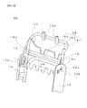
- FIG. 3 is a schematic explanatory view of a frame used for the center-foldable seat back
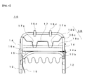
- FIG. 4 is an explanatory view of the front side of FIG. 3
- FIG. 5 is an explanatory view of the back surface side of FIG. 3 .
- a vehicle seat S of this embodiment includes a seat cushion SP, a center-foldable seat back SB, and a headrest HR.
- the center-foldable seat back SB is configured so that a seat back upper part UB can be tilted forward relative to a seat back lower part LB, and at the sides on the front surface of the center-foldable seat back SB, regular rugged stripes T are formed.
- regular rugged stripes T are formed at the center-folding time, orderly contraction can be accomplished, and at the erecting time, regular restoration can be accomplished. Therefore, wrinkles can be prevented from occurring fixedly so that the appearance can be improved.
- the center-foldable seat back SB includes a back frame 10, a pad 20, and a trim cover 30.
- the back frame 10 includes, as principal elements, side frames 12, connecting frames 14, a lower frame 16, and an upper frame 18.
- the side frame 12 is formed with a hinge arm at the lower end on one side thereof, and is fixedly mounted with an arm for a reclining device on the lower side on the other side thereof (both the hinge arm and the arm are not shown).
- the connecting frame 14, which forms a part of center-folding, is interposed between the lower frame 16 and the upper frame 18.
- the lower frame 16 is fixed to the side frames 12, and the connecting frames 14 are disposed at the upper positions of the lower frame 16.
- a reinforcing plate 16a is fixed to the connecting frame 14 and the lower frame 16 by welding to reinforce this portion.
- the upper frame 18 of this embodiment has an U shape.
- An intermediate part of the U shape is an upper part 18b to which guides 18d for headrest pillars (not shown) are fixed, an intermediate part 18a transversely set on both sides of the U shape is provided above the lower frame 16, and the lower parts on both sides of the U shape are connected to the side frames 12.
- Both the end sides of the intermediate part 18a are fixed to the connecting frames 14 and side parts 18c of the U-shaped upper frame 18. As shown in FIG.
- the lower side part of the connecting frame 14 is pivotally supported on the side frame 12 by a shaft part 12b so as to be rotatable, and the upper frame 18 is attached to the connecting frames 14 so as to be tiltable in the front and rear direction, so that the seat back upper part UB can be tilted forward relative to the seat back lower part LB.
- the side frame 12 is formed with an arcuate groove 12a having an arc shape with the shaft part 12b being the center, and the connecting frame 14 is fixedly provided with a guide protrusion 14a inserted in the arcuate groove 12a, so that the configuration is made such that the rotating of the upper frame 18 is regulated by both ends of the arcuate groove 12a.
- the lower frame 16 and the upper frame 18 are mounted with a lower pad 22 and an upper pad 24, respectively, the lower part of the lower pad 22 and the upper part of the upper pad 24 being formed separately.
- the lower pad 22 and the upper pad 24 mounted on the lower frame 16 and the upper frame 18, respectively, are covered with the bag-shaped trim cover 30.
- the pad 20 of the center-foldable seat back SB of this embodiment is separated into the upper pad 24 and the lower pad 22.
- the upper pad 24 is assembled to the upper frame 18, and the lower pad 22 is assembled to the lower frame 16.
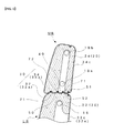
- FIG. 6 is an explanatory sectional view of a relevant portion of the center-foldable seat back SB.
- FIG. 7 is a plan view showing the lower cover 32 side of the trim cover 30 shown in FIG. 6 (in FIG. 7 , the illustration of the upper cover 34 is omitted), schematically showing the sewing construction of the trim cover 30.
- the trim cover 30 shown in the figures is formed of a cloth material such as a fabric, and is sewn into a bag shape by sewing the lower cover 32 covering the lower pad 22 and the upper cover 34 covering the upper pad 24 together.
- the trim cover 30 is provided with the upper cover 34 covering the upper pad 24 and the lower cover 32 covering the lower pad 22.
- the upper cover 34 (that is, the seat back upper part UB side) has a front surface side 34a, side surface sides 34b on both sides, a back surface side 34c, an upper surface side 34d, and a lower surface side 34e, and is sewn into a bag shape as shown in FIGS. 1 and 2 .
- the upper surface side 34d shown in FIG. 2 is formed with mounting holes 33 for mounting the headrest stays.
- the upper cover 34 is sewn into a bag shape open to the downside such as to be capable of accommodating the upper pad 24 including the upper frame 18.
- the lower cover 32 (that is, the seat back lower part LB) has a front surface side 32a, side surface sides 32b on both sides, a back surface side 32c, an upper surface side 32d, and a lower surface side 32e. These surface sides excluding the back surface side 32c and the lower surface side 32e are joined to each other by sewing or the like means.
- the back surface side 32c is configured so as to be capable of being separated from the side surface sides 32b, 32b on both sides. This separation is effected by using vertical slide fasteners 36, 36, which are connecting members sliding in the up and down direction, so that the back surface side 32c can be rolled up.
- the upper cover 34 and the lower cover 32 are sewn together along the entire periphery at the mutual contact position, and can be opened and closed by a connecting member 40 comprising a first connecting part 42 disposed at the sewing position of the front surface side 32a (front cover) and a second connecting part 44 disposed at the sewing position of the rear surface side 32c. That is, the lower cover 32 and the upper cover 34 are sewn together by a seam 71 along the entire periphery of the front surface side (seat cushion side) 32a, the right and left side surface sides 32b, and the back surface side 32c.
- the lower surface side of the seat back lower part LB may be continuous with the front surface side 32a, or may be configured so as to be wrapped by extending the lower part side of the back surface side 32c and by joining it to the lower part of the front surface side 32a by using a joining member such as a hook-and-hoop fastener.
- a cloth piece 50 is provided in the central portion on the front side, the ends of the lower cover 32 and the upper cover 34 and one edge side of one cloth piece 50 are sewn together by the seam 71 around the entire periphery, the cloth piece 50 is extended inward and the other edge side thereof is sewn by a seam 72 to a front cloth tape 42a provided with one portion of the teeth of the open slide fastener 40 (the teeth and the front cloth tape 42 constitute the first connecting part 42), and the central portions on the back side of the lower cover 32 and the upper cover 34 are extended inward and are sewn by the seam 71 around the entire periphery to a rear cloth tape 44a provided with the other portion of the teeth of the open slide fastener 40, whereby the central portion is sewn so as to be opened and closed by one open slide fastener 40.
- the cloth piece 50 is disposed in a substantially central portion on the inside as viewed from the right or left of the trim cover 30. If the trim cover 30 thus configured is provided, by providing the cloth piece 50 in the central portion, the opening and closing work for the connecting member 40 is made easy, and the seat back can be formed so that the seat back upper part UB and the seat back lower part LB are pulled-in deeply.
- Reference numeral 38 denotes a notch part through which the side frame 12 and the like are inserted.
- fastener serving as the connecting member 40 in addition to the aforementioned open slide fastener, a slide fastener (zip fastener), a Delrin fastener, a snap fastener, a hook-and-eye, or the like can be used.
- the internal structure of the seat back SB cannot be seen from the outside, and foreign matters can be prevented from entering deep between the seat back upper part UB and the seat back lower part LB. Therefore, a hindrance to the tilting caused by foreign matters can be eliminated, and at the same time, the appearance as all of the vehicle seat S can also be kept good.
- the connecting member 40 comprising the first connecting part 42 disposed at the sewing position of the upper and lower covers 34 and 32 and the second connecting part 44 disposed at the sewing position of the rear covers 34c and 32c
- the upper pad 24 can be covered with the upper cover 34 merely by closing the connecting member 40 after the upper cover 34 has been put on the upper pad 24. Therefore, the assembling work is made easy, and the work efficiency is enhanced. That is, the upper pad 24 is assembled to the upper frame 18, and the connecting member 40 is kept in an open state by reversingly rolling up the lower cover 32 from the open side.
- FIGS. 8 and 9 show another embodiment in which in addition to the sewing construction of the trim cover 30 in accordance with the above-described embodiment, two cloth pieces 50 are provided in the central portion on the back side.
- the same letters or numerals are applied to members, arrangements, and the like that are the same as or equivalent to those of the above-described embodiment, and the explanation thereof is omitted.
- Cloth pieces 51 and 52 of this embodiment are provided in the central portion on the back side by sewing one edge side thereof by a seam to the ends of the upper surface side 32d of the back surface side 32c of the lower cover 32 and the lower surface side 34e of the back surface side 34c of the upper cover 34, and by sewing the other side edge thereof to the rear cloth tape of the open slide fastener 40 by the seam 71 around the entire periphery.
- the cloth pieces 51 and 52 serve as a gusset part at the tilting time, so that the seat back SB can be configured so that no unreasonable force is applied to all of the trim cover 30. That is, the occurrence of wrinkles on the trim cover 30 can be prevented more reliably by the cloth pieces 51 and 52.
- the seat back upper part UB opens relative to the seat back lower part LB in the state in which the two cloth pieces 51 and 52 act as a gusset, so that the seat back upper part UB can smoothly be tilted forward relative to the seat back lower part LB.
- the position of the connecting part can be adjusted, and the connecting member 40 can be assembled to the optimum position considering the work and the pulling-in effect based on the relationship with the upper and lower frames 18 and 16 and the upper and lower pads 24 and 22.
- FIGS. 10 to 40 show other embodiments of the present invention.
- the same letters or numerals are applied to members, arrangements, and the like that are the same as or equivalent to those of the above-described embodiment, and the explanation thereof is omitted.
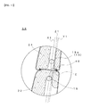
- the connecting member 40 of the embodiment shown in FIG. 10 is mounted so that the first connecting part 42 and the second connecting part, or the center Y1 of the connecting member 40 is located on the front surface side of the seat back SB so as to be distant from the vertical line X1 connecting the upper frame 18 to the lower frame 16.
- the upper and lower pads 24 and 22 each have a shape such that the front surface portion thereof contacting with the seated person is thick, the upper frame 18 and the lower frame 16 are generally disposed on the rear side, not in the central portion, of the width in the front and rear direction of the seat back. If the connecting member 40 is also displaced at the rear like the upper and lower frames 18 and 16, when a center-folding mechanism is operated, the trim cover 30 and the connecting member 40 also move back and forth together. Therefore, after repeated operations, the position of the connecting member 40 shifts, and distortion may occur on the cover surface of the upper cover or the lower cover.
- the connecting member 40 of this embodiment is mounted so that the center Y1 of the connecting member 40 is located on the back surface side of the seat back SB so as to be distant from the vertical line X1 connecting the upper frame 18 to the lower frame 16.
- the upper frame 18 supporting the seat back upper part UB and the lower frame 16 supporting the seat back lower part LB are disposed, and these frames are present on the rear (back surface) side of the connecting member 40, so that these frames become a hindrance to work efficiency.
- the connecting member 40 which has been located at a position at which work is difficult to do because it is held between the upper frame 18 and the lower frame 16, is located in the square region E (indicated by the chain line) shown in FIG. 11 , and is present at a rear position at which assembly is easy to do. Therefore, the workability for the work performed from the rear can be improved.
- the vertical line X1 is the line connecting the centers of the cross sections of the upper frame 18 and the lower frame 16.
- the vertical line may be a line connecting any positions of the cross sections of the upper frame 18 and the lower frame 16.
- the front end of the connecting member 40 is arranged at the rear of the rear ends of the upper and lower frames 18 and 16, so that operation can be performed at a position more separate from between the upper and lower frames 18 and 16. Therefore, the workability can be improved further.
- the connecting member is arranged on the front side of the rear end part of the seat cushion, the connecting member can be mounted easily without the increase in size of the seat back SB.
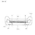
- the back surface side of the lower pad 22 is a space part, in which no pad material is disposed, so as to be usable for other purposes (for example, the storage of magazines). Therefore, as indicated by the lines R in FIG. 12 , the pad material, which is placed from the rear, is formed so as to be arranged to positions close to both sides of the back surface.
- the lower cover 32 can be separated at positions between the back surface side 32c and the side surface side 32b by vertical slide fasteners 36, 36, which are connecting members.
- the vertical slide fasteners 36, 36 are attached as two assembling connecting members directed to the up and down direction on the back surface of the seat back SB.
- the start point and the end point of the vertical slide fasteners 36, 36 are arranged on the outside of both ends of the pad 20 with which the upper and lower frames 18 and 16 are covered.
- the end part of the pad 20 can be made in a state of being connected more strongly by the vertical slide fasteners 36, 36, so that sagging caused by the end part of the lower pad 22 can be prevented.
- the start point and the end point of the connecting member 40 are arranged on the outside of both ends (lines R in FIG. 12 ) on the inside of the pad 20 (in FIG. 12 , the lower pad 22) with which the upper and lower frames 18 and 16 are covered.
- the trim cover 30 can be put in a state of being connected more strongly by the connecting member 40, so that sagging can be prevented.
- the vertical slide fasteners 36, 36 are disposed in the seat back lower part LB so as to have a space equal to or greater than the width of the connecting member 40 in the relation with the connecting member 40.
- FIG. 12 shows an embodiment in which the arrangement space of the vertical slide fasteners 36, 36 is equal to the width of the connecting member 40.
- FIG. 13 which is a figure similar to FIG. 12 , shows an embodiment in which the arrangement space between the vertical slide fasteners 36, 36 is greater than the width of the connecting member 40.
- the configuration is made such that the arrangement space (width) of the two vertical slide fasteners 36, 36 directed to the up and down direction on the back surface of the seat back SB is greater than the width of the inner end part of the cushion covering the side frame 12 from the rear. Therefore, at the time of assembling, the work can be performed with a wider field of vision. Also, the pad 20 part located on the outside is also pulled to the inside, so that the shape becomes sharp.
- a portion overlapping on the arrangement position of the vertical slide fastener 36 in an upper part of the lower pad 22 is formed as a notch part 22a.
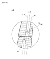
- the configuration is made such that the extension Y1 in the up and down direction of the central portion of the connecting member 40 does not coincide with either of the extension line X2 in the up and down direction of the upper frame 18 and the extension line X3 in the up and down direction of the lower frame 16.
- FIG. 17 shows an embodiment in which the extension Y1 in the up and down direction of the central portion of the connecting member 40 coincide with the extension line X3 in the up and down direction of the lower frame 16, but does not coincide with the extension line X2 in the up and down direction of the upper frame 18.
- FIG. 18 shows an embodiment in which all of the extension line X2 in the up and down direction of the upper frame 18, the extension line X3 in the up and down direction of the lower frame 16, and the extension Y1 in the up and down direction of the central portion of the connecting member 40 do not coincide with each other.
- the back frame of a seat back that is not of a center-foldable type is generally formed of one frame, whereas the center-foldable seat back SB is divided into two so that the upper frame 18 is tilted. Therefore, to keep the strength of the back frame 10, it is preferable that the upper frame 18 on the tilting side be made large.
- the size of the seat back SB is restricted, there arises a disadvantage that if the upper frame 18 is made large, the distance between the upper frame 18 and the lower frame 16 decreases.
- the frame (pipe) that is present above and below the connecting member 40 becomes a hindrance, which presents a disadvantage that the opening and closing work for the connecting member 40 requires much time and labor, and the workability at the time when the trim cover 30 is placed is poor.
- the configuration is made such that the extension Y1 in the up and down direction of the central portion of the connecting member 40 does not coincide with either of the extension line X2 in the up and down direction of the upper frame 18 and the extension line X3 in the up and down direction of the lower frame 16. Therefore, the lower frame 16 and the upper frame 18 are assembled so as not to coincide with and not to overlap on the connecting member 40 in the front and rear direction, so that the assembly is easy to do.
- the connecting member 40 fastener or clip
- the opening and closing work for the connecting member 40 can be performed in the state in which the upper frame 18 is tilted forward, so that the work space on the upper side is secured further. Therefore, the workability of the work performed from the rear is improved. In such a case, even if the positions of the upper frame 18 and the lower frame 16 change, the trim cover 30 using the same connecting member 40 can be placed.
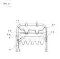
- FIGS. 19 to 23 show other embodiments, showing an embodiment in which a relief portion (expanded portion) is provided on the side on which the upper and lower frames 18 and 16 face to the connecting member 40.
- a relief portion expanded portion
- the assembling can be performed easily without considering the arrangement relationship among the extension line X2 in the up and down direction of the upper frame 18, the extension line X3 in the up and down direction of the lower frame 16, and the extension Y1 in the up and down direction of the central portion of the connecting member 40. That is, the presence of the relief portion secures the work space, thereby improving the workability further.
- FIGS. 19 and 20 shows an embodiment in which the upper frame 18 and the lower frame 16 expand from the side to the center side.
- consideration is made to prevent interference of both end parts of the connecting member 40, the vertical slide fasteners 36, and the surrounding wire 17 with each other.
- FIGS. 21 and 22 show an embodiment in which the upper frame 18 and the lower frame 16 are provided with the relief portions (the expanded portions) at the side positions.
- the start point and the end point of the connecting member 40 can be arranged at the positions of the relief portions.
- FIG. 23 shows an embodiment in which the side on which the lower side of the intermediate part 18a of the upper frame 18 faces to the connecting member 40, that is, the lower side is made thin to secure the work space.
- the reinforcing plate of the lower frame 16 is cut out at the position indicated by letter M in FIG. 23 , whereby the work space relating to the connecting member is secured, and the interference is prevented.
- the work space can also be secured by making the intermediate part 18a itself of the upper frame 18 thinner (smaller in diameter) than the lower frame 16.
- the intermediate part 18a itself of the upper frame 18 is formed by a pipe having a flattened shape from the up and down direction, and is attached so that the flat surface of pipe is substantially horizontal, the work space can be secured in the same manner.
- the intermediate part 18a is attached so that the direction of the flattened surface of the intermediate part 18a is parallel with the direction in which the worker inserts his/her hand from the rear slantwise lower side when placing the trim cover 30, the workability is improved further.
- the above-described embodiment is an embodiment in which the upper frame 18 is modified variously as a work region securing means because the connecting member 40 is arranged at a position closer to the upper frame 18 than to the lower frame 16.
- the connecting member 40 is arranged close to the lower frame 16 by deforming the side on which the lower frame 16 faces to the connecting member 40 in the same way as the above-described various deformations of the upper frame, the work space between the connecting member 40 and the lower frame 16 can be secured, so that the same effect can be achieved.
- the workability is improved further by performing work in the state in which the upper frame is tilted.
- FIG. 24 shows an embodiment in which the lower pad 22 is assembled so as to surround the periphery of the lower frame 16.
- the upper pad 24 is formed with an extension part 24a that extends rearward so that the lower end part rear side thereof is interposed between the intermediate part 18a of the upper frame 18 and the connecting member 40.
- the space between the upper frame 18 and the lower frame 16 must be decreased.
- an abnormal sound may be produced, or the connecting member 40 may be damaged.
- This extension part 24a is a contact preventing means.
- the contact of the connecting member 40 with the upper frame 18 can be restrained, so that the production of abnormal sound can be suppressed.
- the lower pad 22 is also interposed between the lower frame 16 and the connecting member 40. Therefore, the contact of the connecting member 40 with the lower frame 16 can be restrained, so that the production of abnormal sound can be suppressed. Also, the damage to the connecting member 40 can be restrained.
- FIG. 25 shows an embodiment in which the extension part 24a of the upper pad 24 has a shape such that the extension part 24a is further extended rearward and the rear end part thereof is slightly raised upward to cover the upper frame 18.
- the lower pad 22 is also provided so as to cover the lower frame 16. If the upper and lower pads 24 and 22 have a shape such as to cover the upper and lower frames 18 and 16, respectively, the production of abnormal sound caused by the contact can be suppressed, and also the positional shift of the upper and lower pads 24 and 22 and the connecting member 40 caused by vibrations or the like can be prevented.
- the upper pad 24 (or the lower pad 22) need not completely cover the upper frame 18 (or the lower frame 18), and the space through which the pad surrounds the frame has only to be smaller than the width of the connecting member 4.
- the upper frame 16 side of the lower end part of the upper pad 24 extends toward the direction of the upper frame 16 (that is, the inside direction of the upper pad 24) to an extent such as not to hinder the opening and closing of the connecting member 40, and the space smaller than the width of the connecting member 4 is formed.
- the inside lower end part of the upper pad 24 is provided so as to extend downward to an extent to push the periphery of the connecting member.
- the configuration can be made such that the upper pad 24 is provided with the extension part 24a that is the same as in the embodiment shown in FIG. 24 , and the lower pad 22 is not provided with a cushion at a position at which the connecting member 40 is arranged.
- the contact preventing means since the upper pad 24 and/or the lower pad 22 are used as the contact preventing means, a separate member need not be used to prevent an abnormal sound caused by the contact, so that the number of parts can be reduced. Also, the work for attaching the pad 20 to the upper and lower frames 18 and 16 is simplified.
- the welded portion becomes wide in width including the welded members. Therefore, by attaching the upper pad 24 or the lower pad 24 as the contact preventing means so as to intrude between the welded portion and the connecting member 40 at the side position of the upper frame 18 or the lower frame 16 as well, the production of abnormal sound caused by the contact of the connecting member 40 with the welded portion can be prevented.
- the shaft part 12b which is the rotation axis of the upper frame 18 supporting the seat back upper part UB, is arranged below the lower frame 16 supporting the seat back lower part LB, and the seat back upper part US is configured so as to be tiltable forward around the shaft part 12b relative to the seat back lower part LB.
- the center-foldable seat back SB has a bad appearance because when the seat back upper part UB tilts, the clearance and the difference in level in the center-folding portion increase. Therefore, in the embodiment shown in FIG. 28 , by arranging the shaft part 12b below the lower frame 16, the movement in the up and down direction at the time when the seat back upper part UB tilts can be decreased, so that the clearance is decreased, and a preferable clearance can be maintained.
- an extension part 24c formed by extending the front surface lower end part of the upper pad 24 of the seat back upper part UB downward, at the tilting time, the spread of clearance can be restrained by the extension part 24c so that the appearance is improved. Also, if a lower end surface 24d of the upper pad 24 of the seat back upper part UB is formed in a shape following the movement path of the seat back upper part UB, that is, an arcuate shape, the clearance can be made small as far as possible. Therefore, the clearance does not spread at the time of movement, and the seat back upper part UB can move in a fixed state, so that the appearance of the center-folding portion can be improved.
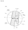
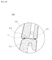
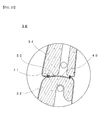
- a concave part 24f and a concave part 22f each having a rectangular cross section, serving as the contact preventing means, are provided between the upper pad 24 and the connecting member 40 and between the lower pad 22 and the connecting member 40, respectively, so as to surround the connecting member 40.
- the concave parts are formed at the arrangement position of the connecting member 40 so as to surround the connecting member 40, especially, so as to include the range in which the connecting member 40 is moved by the tilting of the seat back upper part UB, spaces can be secured between the upper pad 24 and the connecting member 40 and between the lower pad 22 and the connecting member 40. Therefore, when the seat back upper part UB is tilted, the connecting member 40 is less liable to be caught by the upper pad 24 and the lower pad 22, and moves smoothly.
- the connecting member 40 When the connecting member 40 is opened or closed, the connecting member 40 can be prevented from biting the upper pad 24 and the lower pad 22, so that the workability for opening and closing the connecting member 40 is enhanced. Further, since the connecting member 40 does not come into contact with the upper pad 24 and the lower pad 22 when the seat back upper part UB is tilted, an abnormal sound can be prevented from being produced by the contact.
- the concave part 24f formed between the upper pad 24 and the connecting member 40 and the concave part 22f formed between the lower pad 22 and the connecting member 40 each may have a semi-elliptical cross section as in the embodiment shown in FIG. 30 .
- These concave parts 24f and 22f each may have any shape such that a fixed space is formed between the connecting member 40 and the upper and lower pads 24 and 22.
- the upper pad 24 and the lower pad 22 may be arranged so as not to be present around the arrangement position of the connecting member 22.
- the center-foldable seat back SB is a center-foldable seat back SB in which the seat back upper part UB can be tilted forward relative to the seat back lower part LB.
- the method of manufacturing the center-foldable seat back SB includes a back frame producing step S1, a trim cover producing step S2, a tilting step S3, a seat back upper part covering step S4, a closing step S4, and a seat back lower part covering step S6.
- the back frame producing step S1 and the trim cover producing step S2 can be carried out in advance by separate processes.
- the tilting step S3, the seat back upper part covering step S4, the closing step S5, and the seat back lower part covering step S6 are steps carried out continuously. For the seat back upper part covering step and the tilting step, either of them may be carried out prior.
- the back frame 10 which has the upper frame 18 supporting the seat back upper part UB and the lower frame 16 supporting the seat back lower part LB and is configured so that the upper frame 18 is connected so as to be tiltable relative to the lower frame 16, is produced.
- the upper cover 34 and the lower cover 32 are sewn together along the entire periphery at the mutual contact position, the first connecting part 42 is disposed at the sewing position of the front cover 34a, 32a, and the second connecting part 44 is disposed at the sewing position of the rear cover 34c, 32c, whereby the trim cover 30 to which the connecting member 40 is attached is produced.
- FIG. 33 is an explanatory view of the center-foldable seat back SB after the upper pad 24 and the upper cover 34 have been attached to the upper frame 18.
- the upper frame 18 may be tilted relative to the lower frame 16 before the upper pad 24 and the upper cover 34 are attached to the upper frame 18 as in the tilting step S3.
- the state in which the upper frame 18 is tilted farthest to the front in the tilting step S3 is a state in which the space at the rear of the upper frame 18 and the lower frame 16 opens largest, and a state in which the space above the connecting member 40 is secured.
- the work region for the work of placing the trim cover 30 from the rear of the back frame 10, especially, the work of connecting the first connecting part 42 and the second connecting part 44 to each other is secured so as to be the largest. Therefore, when the trim cover 30 is placed in the method of manufacturing the center-foldable seat back SB, the work is preferably performed in this tilting state.
- the upper pad 24 is assembled to the upper frame 18 while the upper frame 18 is held in a state of being tilted in the tilting step S3, and the upper cover 34 of the trim cover 30 is put on the upper pad 24. Then, as shown in FIG. 34 , the portion located between the vertical slide fasteners 36, 36 on the back surface side of the lower cover 32 is reversingly rolled up from the open side, and the connecting member 40 is held in an open state. Thereafter, all of the upper frame 18 to which the upper pad 24 is assembled is inserted into the upper cover 34.
- the connecting member 40 of the trim cover 30 is closed from between the lower frame 16 and the intermediate part 18a of the upper frame 18 to close the upper cover 34.
- the lower pad is assembled to the lower frame 16
- the lower cover 32 of the trim cover 30 is rolled down, and all of the lower frame 16 to which the lower pad 22 is assembled is disposed on the inside of the lower cover 32, whereby the open side is finally closed.
- the trim cover 30 is assembled in the state in which the upper frame 18 is held in a state of being tilted in the tilting step S3, the region of work for the connecting member 40 becomes large, and especially the space above the connecting member 40 is secured. Therefore, the assembly is easy to do so that the center-foldable seat back having features of the center-foldable seat back of the present invention can be manufactured with high efficiency.
- Steps 1 to 4 Steps 3 and 4 are carried out after Step 1 or Step 2.
- any sewing method can be used, such as plural-piece sewing and two-piece sewing.
- various sewing methods may be mixed. The sewing method can be selected considering the load applied to the sewing portion, the elongation, and the like.
Landscapes
- Engineering & Computer Science (AREA)
- Aviation & Aerospace Engineering (AREA)
- Transportation (AREA)
- Mechanical Engineering (AREA)
- Textile Engineering (AREA)
- Seats For Vehicles (AREA)
- Chair Legs, Seat Parts, And Backrests (AREA)
Abstract
Description
- The present invention relates to a center-foldable seat back, a vehicle seat provided with the center-foldable seat back, and a method of manufacturing the center-foldable seat back. More particularly, it relates to a center-foldable seat back in which a seat back upper part of the seat back can be tilted forward relative to a seat back lower part, a vehicle seat provided with the center-foldable seat back, and a method of manufacturing the center-foldable seat back.
- A center-foldable seat back is a design with an associated technique enabling a seat back upper part to tilt forward relative to a seat back lower part, and various types of designs and associated techniques for the center-foldable seat back have conventionally been proposed.
- Since the center-foldable seat back is configured so that the seat back upper part can be tilted forward relative to the seat back lower part, various designs have been made in covering the seat back upper part and the seat back lower part with a trim cover.
For example, as the trim cover, a technique has been known in which the seat back upper part is covered with an upper cover, the seat back lower part is covered with a lower cover, and the upper cover and the lower cover are sewn together along the entire periphery so that no gap is provided between the seat back upper part and the seat back lower part. According to this technique, the seat back can be configured so that the internal structure of the seat back is not exposed to the outside due to the trim cover, and no gap is provided between the seat back upper part and the seat back lower part. - For the center-foldable seat back provided with the trim cover in which the upper cover and the lower cover are sewn together along the entire periphery, a technique has been proposed in which the trim cover is provided with a tension cloth by being extended inward from the upper cover and the lower cover of the trim cover to modulate the pulled-in state and to prevent wrinkles from occurring on the seat surface side of trim cover when the upper frame tilts.
- For example, as the proposed technique, a technique has been proposed in which a plurality of tension cloths folded double in a bag shape are sewn together to the peripheral ends of the upper cover and the lower cover of the trim cover with an appropriate space being provided therebetween, an extensible member such as a rubber string is inserted through the tension cloths, and the ends of the extensible member are fixed to each other by a hook ring (Patent Document 1).
- As another proposed technique, a technique has been proposed in which a tension cloth in the front and rear direction is provided so as to extend inward from the ends of a central portion excluding the right and left portions on the inside of the trim cover as side frame insertion parts, the rear side edge and the front side edge of tension cloth are fixed to each other by a hook ring, and a wire supporting the tension cloth is provided so as to project downward from an upper frame so that the pressing force can be changed in an erected state or a tilted state of the upper frame (Patent Document 2).
- As still another proposed technique, a technique has also been proposed in which a band-like rubber string provided with a resin hook at the front side edge thereof is provided in the back-side central portion, a tension cloth is provided in the front-side central portion, the rubber string is locked to a wire projecting downward from an upper frame by the resin hook to pull the back-side central portion, and the front-side tension cloth is fixed to a back-side joint flap and is pulled (Patent Document 3).
- For the above-described center-foldable seat back, it is anticipated that the pulled-in state is modulated by the tension cloth, and wrinkles are prevented from occurring on the seat surface side of the trim cover.
- Patent Document 1: Japanese Unexamined Patent Application Publication No.
2001-180343 Figure 4 ) - Patent Document 2: Japanese Unexamined Patent Application Publication No.
2001-197956 - Patent Document 3: Japanese Unexamined Patent Application Publication No.
2001-199266 - All of the above-described proposed techniques have a disadvantage that the construction is complicated, so that much time and labor are required for putting the trim cover including the assembling of tension cloth and other members, thereby lowering the work efficiency. That is, in addition to the work for putting the trim cover, the hook ring and the like must be installed in a covered state, so that it is necessary to perform work in a very tight space, which presents a disadvantage that not only the worker requires high skill but also the work efficiency is low.
Also, in the above-described proposed techniques, the trim cover must be put between the upper frame and the lower frame, and further work for applying tension to the tension cloth by another member must be performed. Therefore, improvement has not been made on a point on which the trim cover is put considering the upper frame and the lower frame. - An object of the present invention is to provide a center-foldable seat back in which a seat back upper part can be tilted forward relative to a seat back lower part, wherein when an upper pad and a lower pad are covered with a trim cover sewn along the entire periphery at the mutual contact position of an upper cover and a lower cover, the pulled-in state can be modulated, wrinkles can be prevented from occurring on the seat surface side of the trim cover, the trim cover itself can be assembled easily, the work efficiency is high, and the appearance of all of the seat can be kept good, a vehicle seat provided with the center-foldable seat back, and a method of manufacturing the center-foldable seat back.
- Another object of the present invention is to provide a center-foldable seat back in which even if the design is made so that upper and lower frames of the seat back keep their strength, the workability of work for covering an upper pad and a lower pad with a trim cover sewn along the entire periphery at the mutual contact position of an upper cover and a lower cover can be improved, and the efficiency thereof can be enhanced, a vehicle seat provided with the center-foldable seat back, and a method of manufacturing the center-foldable seat back.
- To achieve the above objects, the present invention provides a center-foldable seat back in which a seat back upper part can be tilted forward relative to a seat back lower part, the seat back comprising a back frame having an upper frame supporting the seat back upper part and a lower frame supporting the seat back lower part, the upper frame being connected so as to be tiltable relative to the lower frame; an upper pad assembled to the upper frame and a lower pad assembled to the lower frame; and a trim cover for covering the upper pad and the lower pad, characterized in that the trim cover is sewn along the entire periphery at a mutual contact position of an upper cover and a lower cover, and can be opened and closed by a connecting member comprising a first connecting part disposed at a sewing position of a front cover and a second connecting part disposed at a sewing position of a rear cover.
- By sewing the mutual contact positions of the upper cover and the lower cover along the entire periphery as described above, the internal structure of the seat back cannot be seen from the outside, and foreign matters can be prevented from entering deep between the seat back upper part and the seat back lower part. Therefore, a hindrance to the tilting caused by foreign matters can be eliminated, and at the same time, the appearance as all of the vehicle seat can also be kept good.
- Also, by making the configuration such that the trim cover can be opened and closed by the connecting member comprising the first connecting part disposed at the sewing position of the front cover and the second connecting part disposed at the sewing position of the rear cover, since the openable and closable connecting member is used, the upper pad can be covered with the upper cover merely by closing the connecting member after the upper pad is covered with the upper cover. Therefore, the assembling work is easy to do, and the work efficiency is enhanced. That is, the trim cover can be placed easily by simple work such that after the upper pad has been assembled to the upper frame and the lower cover has been reversingly rolled up from the open side to keep a state in which the connecting member is open, all of the frame to which the upper pad is assembled is inserted into the upper cover and the upper cover is placed on the upper pad, and next, after the connecting member has been closed to close the upper cover, the lower pad is assembled to the lower frame and the lower cover is rolled down to finally close the open side of the lower cover.
- Also, by closing the connecting member, the sewing portion of the upper cover and the lower cover is pulled to the inside of the seat back, so that a pulling-in effect is produced, and the seat back upper part and the seat back lower part each has a sharp shape like a separate body. Therefore, the occurrence of wrinkles can be prevented.
- It is preferable that a cloth piece be interposed between the sewing portion of the upper cover and the lower cover located on a front side of the seat back of the trim cover and the first connecting part or between the sewing portion of the upper cover and the lower cover located on a rear side of the seat back and the second connecting part.
If the cloth piece is interposed in this manner, the positions of the connecting members can be adjusted, and the connecting member can be assembled at a position that is optimum considering the work and the pulling-in effect based on the relationship with the upper and lower frames and the upper and lower pads. - Also, it is preferable that the cloth piece be disposed in a central portion on the inside of the trim cover. By disposing the cloth piece in the central portion in this manner, the opening and closing work for the connecting member is easy to do, and a portion between the seat back upper part and the seat back lower part can be formed so as to be pulled-in deeply.
- It is preferable that the connecting member be any one of a slide fastener, a Delrin fastener, an open slide fastener, a snap faster, and a hook-and-eye. Thus, the connecting member can use various types of members. In particular, it is preferable that the connecting member be any one of a slide fastener, a Delrin fastener, and an open slide fastener, and only one stripe of connecting member be used.
- Thus, especially in the case where the slide fastener is used, only one stripe of connecting member has only to be provided, so that the number of parts can be reduced, and the assembling can be performed by opening and closing the connecting member by sliding in a right and left direction. Therefore, the connection in the front and rear direction between the seat back upper part and the seat back lower part of the trim cover can be made reliable. Further, since the operation is merely a sliding one, the work efficiency can be enhanced even in a very tight work space between the seat back upper part and the seat back lower part. In the case where the open slide fastener is used, an endmost locking piece of the connecting member slips off, and the connecting member separates to the right and left, so that the assembling work is very easy.
- Also, it is preferable that the connecting member be attached so that the center thereof is located on the back surface side of a vertical line connecting the upper frame to the lower frame.
- Generally, the back frame of the seat back that is not of a center-foldable type consists of one frame, whereas the center-foldable seat back is divided into two, the upper frame supporting the seat back upper part and the lower frame supporting the seat back lower part, to tilt the upper frame. These frames (pipes) are present above, below, or at the rear (back surface) side of the connecting member for connecting the sewing portions at the front and rear of the upper cover and the lower cover, which may become a hindrance to the work efficiency of the opening and closing work for the connecting member.
- For the center-foldable seat back, to keep the strength of the back frame, the upper frame, which is on a tilt side, is preferably made large. However, since the size of the seat back is restricted, if the upper frame is made large, the distance between the upper frame and the lower frame decreases. That is, as described above, when the trim cover is placed, the frame (pipe) that is present above, below, or at the rear of the connecting member becomes a hindrance, which presents a disadvantage that the opening and closing work for the connecting member requires much time and labor, and the workability at the time when the trim cover is placed is poor.
- Accordingly, by locating a center of the connecting member on the back surface side of a vertical line connecting the upper frame to the lower frame, the connecting member is located at a rear position of the upper frame and the lower frame at which the assembly is easy to do. Therefore, the workability of the work performed from the rear can be improved.
- Further, it is preferable that assembling be performed so that a vertical extension line of one frame of the upper frame and the lower frame, a vertical extension of the central portion of the connecting member, and a vertical extension line of the other frame of the upper frame and the lower frame do not coincide with each other.
- Since the configuration is made such that the vertical extension line of the upper frame, the vertical extension line of the lower frame, and the vertical extension of the central portion of the connecting member do not coincide with each other. Therefore, the lower frame and the upper frame are assembled so as not to coincide with and not to overlap on the connecting member in the front and rear direction, the assembly is easy to do.
- At this time, the lower frame of the connecting member (fastener or clip) connecting the upper and lower covers to each other can also be arranged at a front of the upper frame (the lower frame lies at the front). In this case, the work space is secured on the lower side, so that the workability of the work performed from the rear can be improved. In particular, since the opening and closing work for the connecting member can be performed in a state in which the upper frame is tilted forward, the work space on the upper side is further secured, and the workability of the work performed from the rear is improved.
In such a case, even if the positions in the front and rear direction of the upper frame and the lower frame change, these frames can be covered with the trim cover using the same connecting member. - Further, it is preferable that a contact preventing means be provided between the upper and lower frames and the connecting member.
Since the center-foldable seat back is generally manufactured by being divided as described above, the strength of the center-folding portion must be kept. Therefore, a space between the upper frame and the lower frame must be decreased. However, if the space between the upper and lower frames is decreased, when the connecting member comes into contact with the upper frame or the lower frame, an abnormal sound may be produced, or the connecting member may be damaged. If the contact preventing means is provided between the upper and lower frames and the connecting member, the contact of the connecting member with the reinforcing frame can be restrained, so that the production of abnormal sound can be prevented. - As the contact preventing means, a cushion member (contact restraining member) can be provided between the connecting member and the upper frame. As this cushion member, the upper pad or the lower pad can be used. By doing this, the contact of the connecting member with the upper frame or the lower frame can be restrained, so that the production of abnormal sound can be suppressed.
- As a specific contact preventing means, the pad is extended from the front side of the seat back toward the rear to be interposed between the connecting member and the upper frame or the lower frame. Thereby, the contact of the connecting member with the frame can be restrained, so that the production of abnormal sound can be suppressed.
- As another specific contact preventing means, the pad is provided so as to cover the upper frame or the lower frame with the pad. If the frame is covered with the pad in this manner, the positional shift of the pad or the connecting member caused by vibrations or the like is restrained, so that the production of abnormal sound can be prevented. At this time, the frame need not be covered completely with the pad, and the space between the pads has only to be smaller than the connecting member. Thereby, the connecting member is not brought into contact with the frame, so that the production of abnormal sound can be prevented.
- As still another specific contact preventing means, the pad is installed so as to be positioned between a welded portion of frame and the connecting member. By doing this as well, the production of abnormal sound caused by the contact of the connecting member with the welded portion can be prevented.
- As still another specific contact preventing means, an expanding means for expanding the space between the connecting means and the upper and lower frames can be used. For example, the configuration can be made such that an expanded portion serving as a relief portion is provided on the side on which the upper frame or lower frame faces to the connecting member. In this case, the relief portion in which the upper frame or lower frame faces to the connecting member increases the space, so that the work space is secured. Therefore, the workability is improved further.
This relief portion has only to include portions of a start end and a terminal end of the connecting member. Therefore, the relief portion can be formed between the upper frame and the lower frame, or at the side of the upper frame or the lower frame according to a width of the connecting member. - When the upper frame or the lower frame is joined to the side frame or the like at the side position by welding, the joining is performed so that the welded portion becomes wide in width including the welded members. Since the width of the welded portion becomes narrow, as the contact preventing means, the connecting member is provided at a position avoiding the welded portion, so that the contact of the connecting member with the welded portion can be prevented.
- In the case where the expanding means (expanded portion) for expanding the space between the upper frame and the lower frame is used as the contact preventing means between the connecting member and the upper and lower frames, the connecting member is located between the expanding means, and vertical connecting members are disposed at positions having a width wider than the arrangement width of the connecting member. By adjusting positions of the connecting member and the vertical connecting members in this manner, the contact of the connecting member with the frame is prevented, and the interference of the connecting member with the vertical connecting members is avoided, whereby the workability can be improved.
In the case where the connecting member is provided at a position avoiding the welded portion at the side of the upper frame and the lower frame as the contact preventing means, the vertical connecting members are formed at positions on the outside of the connecting member with the width being further increased. By doing this, the space is increased by the upper frame or the lower frame and the relief portion facing to the connecting member, and also the vertical connecting members do not become a hindrance. Therefore, the work space is secured, and the workability is improved further. - Also, it is preferable that the rotation axis of the upper frame supporting the seat back upper part be arranged below the lower frame supporting the seat back lower part so that the seat back upper part can be tilted forward relative to the seat back lower part.
- It is known that the center-foldable seat back generally has a disadvantage that when the seat back upper part is tilted, the clearance and the difference in level of the center-folding portion increase, and therefore the appearance is bad. Accordingly, by arranging a rotation axis of the seat back upper part below the lower frame, vertical movement at the time when the seat back upper part is tilted can be reduced, so that a preferred width of the clearance can be maintained.
- Also, by forming an extension part formed by extending the front surface lower end part of the upper pad of the seat back upper part downward, at the tilting time, the spread of clearance can be restrained by the extension part so that the appearance is improved.
Further, the lower end surface of the upper pad of the seat back upper part is preferably formed in a shape following the movement path of the seat back upper part,
that is, an arcuate shape. By this configuration, the clearance can be made small as far as possible, and an ideal shape such that the clearance does not spread at the time of movement can be realized. - It is preferable that the first connecting part and the second connecting part be arranged at a position in front of the back frame.
In the seat in which the trim cover of the center-foldable seat back is connected by the connecting member, since the pad has a shape such that the front surface part with which the seated person is in contact is thick, the upper frame and the lower frame are generally disposed on the rear side, not in the central portion, in the longitudinal width of the seat back. At this time, if the connecting member is also arranged at the rear like the frames considering the workability at the time of assembling the seat back, when the center-folding mechanism is operated, the cover and the arranged connecting member also move back and forth together. During the repeated operation, the position of the connecting member shifts, and distortion may occur on the cover surface of the upper cover or the lower cover. - According to the above-described configuration, if the connecting member for connecting the upper and lower covers to each other is arranged at the front of the upper and lower frames for connecting the seat back frame, by arranging the connecting member in the central portion in the front and rear direction of the seat, forces are applied to the connecting member evenly from the front and rear direction so that the cover surface of the cover can be prevented from shifting. Also, if the frames are located to the rear, the thickness on the seat cushion side (front direction) of the pad can also be secured.
- It is preferable that the connecting member be provided in a location in which the upper pad and the lower pad are not arranged. That is, the upper pad covering the upper frame and the lower pad covering the lower frame are hollow, and a space is formed therein. The connecting member is arranged in this space.
By this configuration, the connecting member is not brought into contact with the upper pad and the lower pad. - It is preferable that a contact preventing means be provided between the upper and lower pads and the connecting member.
For example, if a recess (concave part) is formed, as the contact preventing means, in the upper pad and the lower pad at the position of the connecting member especially including a range in which the connecting member is moved by the seat back upper part, when the seat back upper part is tilted, the connecting member is less liable to be caught by the pad, and therefore moves smoothly. In particular, if the recess (concave part) is formed in a lower part of the upper pad, the connecting member can be prevented from being caught by the upper pad moving frequently, and smooth movement thereof can be assured. - It is preferable that two assembling connecting members directed to the up and down direction be formed on the back surface of the seat back, and the width of the assembling connecting members be wider than the width of the inner end part of the lower pad.
By this configuration, the lower cover can be rolled up to outside of the lower pad. Therefore, a wider work range can be secured, and also at the time of assembling, the work can be performed with a wider field of vision. - To achieve the above objects, the present invention provides a vehicle seat provided with a seat cushion and a seat back provided on the rear side of the seat cushion, characterized in that, the vehicle seat comprises the center-foldable seat back described in any one of
claims 1 to 11.
The vehicle seat provided with the center-foldable seat back in accordance with the present invention can have the features, operation, and effects of the center-foldable seat back of the present invention. - To achieve the above objects, the present invention provides a method of manufacturing a center-foldable seat back in which a seat back upper part can be tilted forward relative to a seat back lower part, characterized in that, of the following
Steps 1 to 4,Step 3 andStep 4 are carried out afterStep 1 or Step 2: - Step 1: a seat back upper part covering step in which an upper pad is assembled to an upper frame, an upper cover of a trim cover is put on the upper pad, a lower cover is reversingly rolled up from the open side to hold a connecting member in an open state, and all of the upper frame to which the upper pad is assembled is inserted into the upper cover,
- Step 2: a tilting step in which the upper frame is held in a tilted state by being tilted relative to the lower frame,
- Step 3: a closing step in which the connecting member of the trim cover is closed to close the upper cover, and
- Step 4: a seat back lower part covering step in which after the closing step, all of the lower frame to which a lower pad is assembled is disposed on the inside of the lower cover to finally close the open side.
- To achieve the above objects, the present invention provides a method of manufacturing a center-foldable seat back in which a seat back upper part can be tilted forward relative to a seat back lower part, including a back frame producing step in which a back frame, which has an upper frame supporting the seat back upper part and a lower frame supporting the seat back lower part and is configured so that the upper frame is connected so as to be tiltable relative to the lower frame, is produced; a trim cover producing step in which an upper cover and a lower cover are sewn together along the entire periphery at a mutual contact position, a first connecting part is disposed at the sewing position of a front cover, and a second connecting part is disposed at the sewing position of a rear cover, whereby a trim cover to which a connecting member is attached is produced; a tilting step in which the upper frame produced in the back frame producing step is held in a tilted state by being tilted relative to the lower frame; a seat back upper part covering step in which an upper pad is assembled to the upper frame while the upper frame is held in a state of being tilted in the tilting step, and the upper cover of the trim cover is put on the upper pad; then, the lower cover is reversingly rolled up from an open side, and the connecting member is held in an open state; and thereafter, all of the upper frame to which the upper pad is assembled is inserted into the upper cover; a closing step in which the connecting member of the trim cover is closed to close the upper cover; and a seat back lower part covering step in which after the closing step, a lower pad is assembled to the lower frame, the lower cover of the trim cover is rolled down, and all of the lower frame to which the lower pad is assembled is disposed on the inside of the lower cover, whereby the open side is finally closed.
- Because of the above-described configuration, since the upper frame is assembled in a state of being held in a state of being tilted in the tilting step, the region of work for the connecting member becomes large. Therefore, the center-foldable seat back having features of the center-foldable seat back of the present invention can be manufactured with high efficiency.
- According to the present invention, by sewing the mutual contact positions of the upper cover and the lower cover along the entire periphery, the internal structure of the seat back cannot be seen from the outside, and foreign matters can be prevented from entering deep between the seat back upper part and the seat back lower part. Therefore, a hindrance to the tilting caused by foreign matter can be eliminated, and, at the same time, the appearance as all of the vehicle seat can also be kept good.
Also, because of the configuration such that opening and closing can be performed by the connecting member comprising the first connecting part disposed at the sewing position of the front cover and the second connecting part disposed at the sewing position of the rear cover, since the openable and closable connecting member is used, the upper pad can be covered with the upper cover merely by closing the connecting member after the upper cover has been put on the upper pad. Therefore, the assembling work is made easy, and the work efficiency is enhanced. -
-
FIG. 1 is a schematic perspective view of a vehicle seat provided with a center-foldable seat back; -
FIG. 2 is a perspective view of the back surface side of a center-foldable seat back; -
FIG. 3 is a schematic explanatory view of a frame used for a center-foldable seat back; -
FIG. 4 is a front explanatory view of the front side ofFIG. 3 ; -
FIG. 5 is a rear explanatory view of the back surface side ofFIG. 3 ; -
FIG. 6 is an explanatory sectional view of a relevant portion of a center-foldable seat back; -
FIG. 7 is a plan view showing the lower cover side of the trim cover shown inFIG. 6 ; -
FIG. 8 is an explanatory sectional view of a relevant portion of a center-foldable seat back; -
FIG. 9 is a plan view showing the lower cover side of the trim cover shown inFIG. 8 ; -
FIG. 10 is an enlarged explanatory sectional view of a relevant portion of a center-foldable seat back; -
FIG. 11 is an enlarged explanatory sectional view of a relevant portion of a center-foldable seat back; -
FIG. 12 is a plan view showing the lower cover side of a trim cover of a center-foldable seat back; -
FIG. 13 is a plan view showing the lower cover side of a trim cover of a center-foldable seat back; -
FIG. 14 is an enlarged explanatory sectional view of a relevant portion of a center-foldable seat back; -
FIG. 15 is an explanatory sectional view of a center-foldable seat back, taken along the line A-A ofFIG. 14 ; -
FIG. 16 is an enlarged explanatory sectional view of a relevant portion of a center-foldable seat back; -
FIG. 17 is an enlarged explanatory sectional view of a relevant portion of a center-foldable seat back; -
FIG. 18 is an enlarged explanatory sectional view of a relevant portion of a center-foldable seat back; -
FIG. 19 is a schematic explanatory view of a frame used for a center-foldable seat back; -
FIG. 20 is an explanatory view showing the relationship between a connecting member and back surface-side fasteners of a center-foldable seat back; -
FIG. 21 is a schematic explanatory view of a frame used for a center-foldable seat back; -
FIG. 22 is an explanatory view showing the relationship between a connecting member and back surface-side fasteners of a center-foldable seat back; -
FIG. 23 is a schematic explanatory view of a frame used for a center-foldable seat back; -
FIG. 24 is an enlarged explanatory sectional view of a relevant portion of a center-foldable seat back; -
FIG. 25 is an enlarged explanatory sectional view of a relevant portion of a center-foldable seat back; -
FIG. 26 is an enlarged explanatory sectional view of a relevant portion of a center-foldable seat back; -
FIG. 27 is an enlarged explanatory sectional view of a relevant portion of a center-foldable seat back; -
FIG. 28 is an explanatory sectional view of a relevant portion of a center-foldable seat back; -
FIG. 29 is an enlarged explanatory sectional view of a relevant portion of a center-foldable seat back; -
FIG. 30 is an enlarged explanatory sectional view of a relevant portion of a center-foldable seat back; -
FIG. 31 is an enlarged explanatory sectional view of a relevant portion of a center-foldable seat back; -
FIG. 32 is a flow diagram showing the manufacturing process of a center-foldable seat back; -
FIG. 33 is an explanatory side view of a center-foldable seat back; -
FIG. 34 is an explanatory view showing the manufacture of a center-foldable seat back; -
FIG. 35 is an enlarged explanatory sectional view of a relevant portion of a center-foldable seat back; -
FIG. 36 is an enlarged explanatory sectional view of a relevant portion of a center-foldable seat back; -
FIG. 37 is an enlarged explanatory sectional view of a relevant portion of a center-foldable seat back; -
FIG. 38 is an enlarged explanatory sectional view of a relevant portion of a center-foldable seat back; -
FIG. 39 is an enlarged explanatory sectional view of a relevant portion of a center-foldable seat back; and -
FIG. 40 is an enlarged explanatory sectional view of a relevant portion of a center-foldable seat back. -
- S
- vehicle seat
- SP
- seat cushion / seat surface part
- SB
- center-foldable seat back
- UB
- seat back upper part
- LB
- seat back lower part
- HR
- headrest
- T
- rugged stripes
- E
- region
- M
- notch part
- 10
- back frame
- 12
- side frame
- 12a
- arcuate groove
- 12b
- shaft part
- 14
- connecting frame
- 14a
- guide protrusion
- 16
- lower frame
- 17
- surrounding wire
- 17a
- concave part
- 18
- upper frame
- 18a
- intermediate part
- 18b
- upper part
- 18c
- side part
- 18d
- guide
- 19
- control cable
- 20
- pad
- 22
- lower pad
- 22a
- notch part
- 22f
- concave part
- 24
- upper pad
- 24a, 24c
- extension part
- 24d
- lower end face
- 24f
- concave part
- 30
- trim cover
- 32
- lower cover
- 32a
- front surface side (front cover)
- 32b
- side surface side
- 32c
- back surface side
- 32d
- upper surface side
- 32e
- lower surface side
- 33
- mounting hole
- 34
- upper cover
- 34a
- front surface side (front cover)
- 34b
- side surface side
- 34c
- back surface side
- 34d
- upper surface side
- 34e
- lower surface side
- 36
- vertical slide fastener
- 38
- notch part
- 40
- connecting member
- 42
- first connecting part
- 42a
- front cloth tape
- 44
- second connecting part
- 44a
- rear cloth tape
- 50, 51, 52
- cloth piece
- 71,
- 72 seam
- One embodiment of the present invention will now be described with reference to the accompanying drawings. The members, arrangements, and the like described below do not restrict the present invention, and various changes and modifications can be made within the scope of teachings of the present invention.
FIG. 1 is a schematic perspective view of a vehicle seat provided with a center-foldable seat back,FIG. 2 is a perspective view of the back surface side of the center-foldable seat back,FIG. 3 is a schematic explanatory view of a frame used for the center-foldable seat back,FIG. 4 is an explanatory view of the front side ofFIG. 3 , andFIG. 5 is an explanatory view of the back surface side ofFIG. 3 . - As shown in
FIG. 1 , a vehicle seat S of this embodiment includes a seat cushion SP, a center-foldable seat back SB, and a headrest HR. The center-foldable seat back SB is configured so that a seat back upper part UB can be tilted forward relative to a seat back lower part LB, and at the sides on the front surface of the center-foldable seat back SB, regular rugged stripes T are formed. By these rugged stripes T, at the center-folding time, orderly contraction can be accomplished, and at the erecting time, regular restoration can be accomplished. Therefore, wrinkles can be prevented from occurring fixedly so that the appearance can be improved. - The center-foldable seat back SB includes a
back frame 10, apad 20, and atrim cover 30. Theback frame 10 includes, as principal elements, side frames 12, connectingframes 14, alower frame 16, and anupper frame 18. - The
side frame 12 is formed with a hinge arm at the lower end on one side thereof, and is fixedly mounted with an arm for a reclining device on the lower side on the other side thereof (both the hinge arm and the arm are not shown).
The connectingframe 14, which forms a part of center-folding, is interposed between thelower frame 16 and theupper frame 18. Thelower frame 16 is fixed to the side frames 12, and the connectingframes 14 are disposed at the upper positions of thelower frame 16. Also, between the connectingframe 14 and thelower frame 16, a reinforcing plate 16a is fixed to the connectingframe 14 and thelower frame 16 by welding to reinforce this portion. - The
upper frame 18 of this embodiment has an U shape. An intermediate part of the U shape is an upper part 18b to which guides 18d for headrest pillars (not shown) are fixed, an intermediate part 18a transversely set on both sides of the U shape is provided above thelower frame 16, and the lower parts on both sides of the U shape are connected to the side frames 12. Both the end sides of the intermediate part 18a are fixed to the connectingframes 14 and side parts 18c of the U-shapedupper frame 18. As shown inFIG. 3 , the lower side part of the connectingframe 14 is pivotally supported on theside frame 12 by a shaft part 12b so as to be rotatable, and theupper frame 18 is attached to the connectingframes 14 so as to be tiltable in the front and rear direction, so that the seat back upper part UB can be tilted forward relative to the seat back lower part LB. - As shown in
FIG. 3 , theside frame 12 is formed with an arcuate groove 12a having an arc shape with the shaft part 12b being the center, and the connectingframe 14 is fixedly provided with a guide protrusion 14a inserted in the arcuate groove 12a, so that the configuration is made such that the rotating of theupper frame 18 is regulated by both ends of the arcuate groove 12a. -
Reference numeral 17 denotes a surrounding wire disposed around the headrest pillars and the guides 18d.
The surroundingwire 17 is formed with downwardly concave parts 17a.Reference numeral 19 denotes a control cable for controlling the tilt of theupper frame 18. Thecontrol cable 19 rotates the connectingframes 14, and rotates theupper frame 18 fixed to the connecting frames 14. - The
lower frame 16 and theupper frame 18 are mounted with alower pad 22 and anupper pad 24, respectively, the lower part of thelower pad 22 and the upper part of theupper pad 24 being formed separately. Thelower pad 22 and theupper pad 24 mounted on thelower frame 16 and theupper frame 18, respectively, are covered with the bag-shapedtrim cover 30. - The
pad 20 of the center-foldable seat back SB of this embodiment is separated into theupper pad 24 and thelower pad 22. Theupper pad 24 is assembled to theupper frame 18, and thelower pad 22 is assembled to thelower frame 16. - The
trim cover 30 of this embodiment will be explained in more detail with reference to the accompanying drawings.FIG. 6 is an explanatory sectional view of a relevant portion of the center-foldable seat back SB.FIG. 7 is a plan view showing thelower cover 32 side of thetrim cover 30 shown inFIG. 6 (inFIG. 7 , the illustration of theupper cover 34 is omitted), schematically showing the sewing construction of thetrim cover 30. Thetrim cover 30 shown in the figures is formed of a cloth material such as a fabric, and is sewn into a bag shape by sewing thelower cover 32 covering thelower pad 22 and theupper cover 34 covering theupper pad 24 together. - That is, the
trim cover 30 is provided with theupper cover 34 covering theupper pad 24 and thelower cover 32 covering thelower pad 22. The upper cover 34 (that is, the seat back upper part UB side) has a front surface side 34a, side surface sides 34b on both sides, a back surface side 34c, an upper surface side 34d, and a lower surface side 34e, and is sewn into a bag shape as shown inFIGS. 1 and2 . The upper surface side 34d shown inFIG. 2 is formed with mountingholes 33 for mounting the headrest stays. Theupper cover 34 is sewn into a bag shape open to the downside such as to be capable of accommodating theupper pad 24 including theupper frame 18. - The lower cover 32 (that is, the seat back lower part LB) has a front surface side 32a, side surface sides 32b on both sides, a back surface side 32c, an upper surface side 32d, and a lower surface side 32e. These surface sides excluding the back surface side 32c and the lower surface side 32e are joined to each other by sewing or the like means. The back surface side 32c is configured so as to be capable of being separated from the side surface sides 32b, 32b on both sides. This separation is effected by using
vertical slide fasteners lower cover 32 is sewn into a tubular shape open to the upside such as to be capable of accommodating thelower pad 22 including thelower frame 16. - The
upper cover 34 and thelower cover 32 are sewn together along the entire periphery at the mutual contact position, and can be opened and closed by a connectingmember 40 comprising a first connecting part 42 disposed at the sewing position of the front surface side 32a (front cover) and a second connectingpart 44 disposed at the sewing position of the rear surface side 32c.
That is, thelower cover 32 and theupper cover 34 are sewn together by aseam 71 along the entire periphery of the front surface side (seat cushion side) 32a, the right and left side surface sides 32b, and the back surface side 32c.
The lower surface side of the seat back lower part LB may be continuous with the front surface side 32a, or may be configured so as to be wrapped by extending the lower part side of the back surface side 32c and by joining it to the lower part of the front surface side 32a by using a joining member such as a hook-and-hoop fastener. - On the inside of the
trim cover 30, acloth piece 50 is provided in the central portion on the front side, the ends of thelower cover 32 and theupper cover 34 and one edge side of onecloth piece 50 are sewn together by theseam 71 around the entire periphery, thecloth piece 50 is extended inward and the other edge side thereof is sewn by aseam 72 to a front cloth tape 42a provided with one portion of the teeth of the open slide fastener 40 (the teeth and the front cloth tape 42 constitute the first connecting part 42), and the central portions on the back side of thelower cover 32 and theupper cover 34 are extended inward and are sewn by theseam 71 around the entire periphery to a rear cloth tape 44a provided with the other portion of the teeth of theopen slide fastener 40, whereby the central portion is sewn so as to be opened and closed by oneopen slide fastener 40. - As shown in
FIG. 6 , thecloth piece 50 is disposed in a substantially central portion on the inside as viewed from the right or left of thetrim cover 30. If thetrim cover 30 thus configured is provided, by providing thecloth piece 50 in the central portion, the opening and closing work for the connectingmember 40 is made easy, and the seat back can be formed so that the seat back upper part UB and the seat back lower part LB are pulled-in deeply.Reference numeral 38 denotes a notch part through which theside frame 12 and the like are inserted. - In this embodiment, since the central portion in the front and rear direction is pulled by one
cloth piece 50 and oneopen slide fastener 40 as shown inFIG. 7 , the pulled-in state is modulated by thecloth piece 50, and the occurrence of wrinkles can be prevented by a small number of parts, so that the appearance as all of the vehicle seat S can be kept good. Also, due to the open slide fastener, the lowermost fastener comes off and separates to the right and left, so that the workability is improved. - As the fastener serving as the connecting
member 40, in addition to the aforementioned open slide fastener, a slide fastener (zip fastener), a Delrin fastener, a snap fastener, a hook-and-eye, or the like can be used. - By sewing the mutual contact positions of the
upper cover 34 and thelower cover 32 along the entire periphery, the internal structure of the seat back SB cannot be seen from the outside, and foreign matters can be prevented from entering deep between the seat back upper part UB and the seat back lower part LB. Therefore, a hindrance to the tilting caused by foreign matters can be eliminated, and at the same time, the appearance as all of the vehicle seat S can also be kept good. - Also, because of the configuration such that opening and closing can be performed by the connecting
member 40 comprising the first connecting part 42 disposed at the sewing position of the upper andlower covers part 44 disposed at the sewing position of the rear covers 34c and 32c, theupper pad 24 can be covered with theupper cover 34 merely by closing the connectingmember 40 after theupper cover 34 has been put on theupper pad 24. Therefore, the assembling work is made easy, and the work efficiency is enhanced. That is, theupper pad 24 is assembled to theupper frame 18, and the connectingmember 40 is kept in an open state by reversingly rolling up thelower cover 32 from the open side. Then, all of the frame to which theupper pad 24 is assembled is inserted into theupper cover 34, and theupper cover 34 is put on theupper pad 24. Next, after the connectingmember 40 is closed to close theupper cover 34, thelower pad 22 is assembled to thelower frame 16, and thelower cover 32 is rolled down, whereby thelower cover 32 can be put easily by simple work without time and labor for finally closing the open side of thelower cover 32. - Since the sewing portion of the
upper cover 34 and thelower cover 32 is pulled to the inside of the seat back SB by the closure using the connectingmember 40, a pulling-in effect is achieved between theupper cover 34 and thelower cover 32. Also, since the seat back upper part UB and the seat back lower part LB each has a sharp shape like a separate body, the occurrence or wrinkles can be prevented. - In the above-described embodiment, one
cloth piece 50 is interposed between the sewing portion of theupper cover 34 andlower cover 32, located on the back side of the seat back SB of thetrim cover 30, and one connecting part of the first connecting part 42 and the second connectingpart 44. However,FIGS. 8 and9 show another embodiment in which in addition to the sewing construction of thetrim cover 30 in accordance with the above-described embodiment, twocloth pieces 50 are provided in the central portion on the back side. In this embodiment, the same letters or numerals are applied to members, arrangements, and the like that are the same as or equivalent to those of the above-described embodiment, and the explanation thereof is omitted. - Cloth pieces 51 and 52 of this embodiment are provided in the central portion on the back side by sewing one edge side thereof by a seam to the ends of the upper surface side 32d of the back surface side 32c of the
lower cover 32 and the lower surface side 34e of the back surface side 34c of theupper cover 34, and by sewing the other side edge thereof to the rear cloth tape of theopen slide fastener 40 by theseam 71 around the entire periphery. - If the cloth pieces 51 and 52 are interposed as described above, the cloth pieces 51 and 52 serve as a gusset part at the tilting time, so that the seat back SB can be configured so that no unreasonable force is applied to all of the
trim cover 30. That is, the occurrence of wrinkles on thetrim cover 30 can be prevented more reliably by the cloth pieces 51 and 52. At the same time, with the forward tilting of the seat back upper part UB relative to the seat back lower part LB, the seat back upper part UB opens relative to the seat back lower part LB in the state in which the two cloth pieces 51 and 52 act as a gusset, so that the seat back upper part UB can smoothly be tilted forward relative to the seat back lower part LB. - If the cloth pieces 51 and 52 are interposed as described above, the position of the connecting part can be adjusted, and the connecting
member 40 can be assembled to the optimum position considering the work and the pulling-in effect based on the relationship with the upper andlower frames lower pads -
FIGS. 10 to 40 show other embodiments of the present invention. In these embodiments, the same letters or numerals are applied to members, arrangements, and the like that are the same as or equivalent to those of the above-described embodiment, and the explanation thereof is omitted. - The connecting
member 40 of the embodiment shown inFIG. 10 is mounted so that the first connecting part 42 and the second connecting part, or the center Y1 of the connectingmember 40 is located on the front surface side of the seat back SB so as to be distant from the vertical line X1 connecting theupper frame 18 to thelower frame 16. - In the seat in which the
trim cover 30 of the center-foldable seat back SB is connected by the connectingmember 40, since the upper andlower pads upper frame 18 and thelower frame 16 are generally disposed on the rear side, not in the central portion, of the width in the front and rear direction of the seat back. If the connectingmember 40 is also displaced at the rear like the upper andlower frames trim cover 30 and the connectingmember 40 also move back and forth together. Therefore, after repeated operations, the position of the connectingmember 40 shifts, and distortion may occur on the cover surface of the upper cover or the lower cover. - By disposing the connecting
member 40 in the central portion in the front and rear direction of the seat, forces are applied to the connectingmember 40 evenly from the front and rear direction, so that thetrim cover 30 can be prevented from shifting. - As shown in
FIG. 11 , the connectingmember 40 of this embodiment is mounted so that the center Y1 of the connectingmember 40 is located on the back surface side of the seat back SB so as to be distant from the vertical line X1 connecting theupper frame 18 to thelower frame 16. - On the
back frame 10, theupper frame 18 supporting the seat back upper part UB and thelower frame 16 supporting the seat back lower part LB are disposed, and these frames are present on the rear (back surface) side of the connectingmember 40, so that these frames become a hindrance to work efficiency. However, by locating the center Y1 of the connectingmember 40 on the back surface side so as to be distant from the vertical line X1 connecting theupper frame 18 to thelower frame 16, the connectingmember 40, which has been located at a position at which work is difficult to do because it is held between theupper frame 18 and thelower frame 16, is located in the square region E (indicated by the chain line) shown inFIG. 11 , and is present at a rear position at which assembly is easy to do. Therefore, the workability for the work performed from the rear can be improved. - In this embodiment, the vertical line X1 is the line connecting the centers of the cross sections of the
upper frame 18 and thelower frame 16. However, the vertical line may be a line connecting any positions of the cross sections of theupper frame 18 and thelower frame 16. In the case of the position of the line Z1 inFIG. 11 , the front end of the connectingmember 40 is arranged at the rear of the rear ends of the upper andlower frames lower frames
Also, in this embodiment, as shown inFIG. 11 , since the connecting member is arranged on the front side of the rear end part of the seat cushion, the connecting member can be mounted easily without the increase in size of the seat back SB. - Generally, the back surface side of the
lower pad 22 is a space part, in which no pad material is disposed, so as to be usable for other purposes (for example, the storage of magazines). Therefore, as indicated by the lines R inFIG. 12 , the pad material, which is placed from the rear, is formed so as to be arranged to positions close to both sides of the back surface. In this embodiment, thelower cover 32 can be separated at positions between the back surface side 32c and the side surface side 32b byvertical slide fasteners FIG. 12 , thevertical slide fasteners vertical slide fasteners - Also, the start point and the end point of the
vertical slide fasteners pad 20 with which the upper andlower frames lower pad 22 is covered with thetrim cover 30 in this manner, the end part of thepad 20 can be made in a state of being connected more strongly by thevertical slide fasteners lower pad 22 can be prevented. - Also, the start point and the end point of the connecting
member 40 are arranged on the outside of both ends (lines R inFIG. 12 ) on the inside of the pad 20 (inFIG. 12 , the lower pad 22) with which the upper andlower frames lower pad 22 is covered with thetrim cover 30 in this manner, the trim cover can be put in a state of being connected more strongly by the connectingmember 40, so that sagging can be prevented. - Also, the
vertical slide fasteners member 40 in the relation with the connectingmember 40.FIG. 12 shows an embodiment in which the arrangement space of thevertical slide fasteners member 40.FIG. 13 , which is a figure similar toFIG. 12 , shows an embodiment in which the arrangement space between thevertical slide fasteners member 40. - According to this embodiment, the configuration is made such that the arrangement space (width) of the two
vertical slide fasteners side frame 12 from the rear. Therefore, at the time of assembling, the work can be performed with a wider field of vision. Also, thepad 20 part located on the outside is also pulled to the inside, so that the shape becomes sharp. - As shown in
FIGS. 14 and15 , a portion overlapping on the arrangement position of thevertical slide fastener 36 in an upper part of thelower pad 22 is formed as a notch part 22a. By forming the notch part 22a in this manner, when thevertical slide fastener 36 is located at an upper end position, the interference of the slider of thevertical slide fastener 36 with thepad 20 can be prevented, so that damage to thepad 20 or biting of the slider into thepad 20 can be prevented. - As shown in
FIGS. 16 to 18 , regarding the extension line X2 in the up and down direction of theupper frame 18, the extension line X3 in the up and down direction of thelower frame 16, and the extension Y1 in the up and down direction of the central portion of the connectingmember 40, the configuration is made such that the extension Y1 in the up and down direction of the central portion of the connectingmember 40 does not coincide with either of the extension line X2 in the up and down direction of theupper frame 18 and the extension line X3 in the up and down direction of thelower frame 16.FIG. 16 shows an embodiment in which the extension Y1 in the up and down direction of the central portion of the connectingmember 40 coincide with the extension line X2 in the up and down direction of theupper frame 18, but does not coincide with the extension line X3 in the up and down direction of thelower frame 16. -
FIG. 17 shows an embodiment in which the extension Y1 in the up and down direction of the central portion of the connectingmember 40 coincide with the extension line X3 in the up and down direction of thelower frame 16, but does not coincide with the extension line X2 in the up and down direction of theupper frame 18.
FIG. 18 shows an embodiment in which all of the extension line X2 in the up and down direction of theupper frame 18, the extension line X3 in the up and down direction of thelower frame 16, and the extension Y1 in the up and down direction of the central portion of the connectingmember 40 do not coincide with each other. - The back frame of a seat back that is not of a center-foldable type is generally formed of one frame, whereas the center-foldable seat back SB is divided into two so that the
upper frame 18 is tilted. Therefore, to keep the strength of theback frame 10, it is preferable that theupper frame 18 on the tilting side be made large. However, since the size of the seat back SB is restricted, there arises a disadvantage that if theupper frame 18 is made large, the distance between theupper frame 18 and thelower frame 16 decreases. Thus, when thetrim cover 30 is placed, the frame (pipe) that is present above and below the connectingmember 40 becomes a hindrance, which presents a disadvantage that the opening and closing work for the connectingmember 40 requires much time and labor, and the workability at the time when thetrim cover 30 is placed is poor. - As described above, regarding the extension line X2 in the up and down direction of the
upper frame 18, the extension line X3 in the up and down direction of thelower frame 16, and the extension Y1 in the up and down direction of the central portion of the connectingmember 40, the configuration is made such that the extension Y1 in the up and down direction of the central portion of the connectingmember 40 does not coincide with either of the extension line X2 in the up and down direction of theupper frame 18 and the extension line X3 in the up and down direction of thelower frame 16. Therefore, thelower frame 16 and theupper frame 18 are assembled so as not to coincide with and not to overlap on the connectingmember 40 in the front and rear direction, so that the assembly is easy to do. - At this time, if the configuration is made such that the
lower frame 16 is arranged in the front of theupper frame 18 as shown inFIG. 16 (thelower frame 16 lies in the front), a work space is secured on the lower side, so that the workability of work for assembling, from the rear, the connecting member 40 (fastener or clip) for connecting the upper andlower covers member 40 can be performed in the state in which theupper frame 18 is tilted forward, so that the work space on the upper side is secured further. Therefore, the workability of the work performed from the rear is improved.
In such a case, even if the positions of theupper frame 18 and thelower frame 16 change, thetrim cover 30 using the same connectingmember 40 can be placed. -
FIGS. 19 to 23 show other embodiments, showing an embodiment in which a relief portion (expanded portion) is provided on the side on which the upper andlower frames member 40. By providing the relief portion in this manner, the assembling can be performed easily without considering the arrangement relationship among the extension line X2 in the up and down direction of theupper frame 18, the extension line X3 in the up and down direction of thelower frame 16, and the extension Y1 in the up and down direction of the central portion of the connectingmember 40. That is, the presence of the relief portion secures the work space, thereby improving the workability further. -
FIGS. 19 and20 shows an embodiment in which theupper frame 18 and thelower frame 16 expand from the side to the center side. In the embodiment shown inFIG. 20 , consideration is made to prevent interference of both end parts of the connectingmember 40, thevertical slide fasteners 36, and the surroundingwire 17 with each other. -
FIGS. 21 and22 show an embodiment in which theupper frame 18 and thelower frame 16 are provided with the relief portions (the expanded portions) at the side positions. By this configuration, the start point and the end point of the connectingmember 40 can be arranged at the positions of the relief portions. -
FIG. 23 shows an embodiment in which the side on which the lower side of the intermediate part 18a of theupper frame 18 faces to the connectingmember 40, that is, the lower side is made thin to secure the work space. In this embodiment, the reinforcing plate of thelower frame 16 is cut out at the position indicated by letter M inFIG. 23 , whereby the work space relating to the connecting member is secured, and the interference is prevented. - Although not shown in the Figure, the work space can also be secured by making the intermediate part 18a itself of the
upper frame 18 thinner (smaller in diameter) than thelower frame 16.
Also, if the intermediate part 18a itself of theupper frame 18 is formed by a pipe having a flattened shape from the up and down direction, and is attached so that the flat surface of pipe is substantially horizontal, the work space can be secured in the same manner. In this case, if the intermediate part 18a is attached so that the direction of the flattened surface of the intermediate part 18a is parallel with the direction in which the worker inserts his/her hand from the rear slantwise lower side when placing thetrim cover 30, the workability is improved further. - The above-described embodiment is an embodiment in which the
upper frame 18 is modified variously as a work region securing means because the connectingmember 40 is arranged at a position closer to theupper frame 18 than to thelower frame 16. In the case of the configuration in which the connectingmember 40 is arranged close to thelower frame 16, by deforming the side on which thelower frame 16 faces to the connectingmember 40 in the same way as the above-described various deformations of the upper frame, the work space between the connectingmember 40 and thelower frame 16 can be secured, so that the same effect can be achieved. - In all of the above-described cases, the workability is improved further by performing work in the state in which the upper frame is tilted.
-
FIG. 24 shows an embodiment in which thelower pad 22 is assembled so as to surround the periphery of thelower frame 16. In this embodiment, theupper pad 24 is formed with an extension part 24a that extends rearward so that the lower end part rear side thereof is interposed between the intermediate part 18a of theupper frame 18 and the connectingmember 40. - Generally, to keep the strength of the center-folding portion, the space between the
upper frame 18 and thelower frame 16 must be decreased. As a result, when the connectingmember 40 comes into contact with theupper frame 18 or thelower frame 16, an abnormal sound may be produced, or the connectingmember 40 may be damaged. - This extension part 24a is a contact preventing means. By providing a part of the
upper pad 24 between the connectingmember 40 and theupper frame 18, the contact of the connectingmember 40 with theupper frame 18 can be restrained, so that the production of abnormal sound can be suppressed. Also, since thelower pad 22 is also interposed between thelower frame 16 and the connectingmember 40, thelower pad 22 is a contact preventing means. Therefore, the contact of the connectingmember 40 with thelower frame 16 can be restrained, so that the production of abnormal sound can be suppressed. Also, the damage to the connectingmember 40 can be restrained. -
FIG. 25 shows an embodiment in which the extension part 24a of theupper pad 24 has a shape such that the extension part 24a is further extended rearward and the rear end part thereof is slightly raised upward to cover theupper frame 18. Thelower pad 22 is also provided so as to cover thelower frame 16. If the upper andlower pads lower frames lower pads member 40 caused by vibrations or the like can be prevented. - In this case, the upper pad 24 (or the lower pad 22) need not completely cover the upper frame 18 (or the lower frame 18), and the space through which the pad surrounds the frame has only to be smaller than the width of the connecting
member 4. For example, as shown inFIG. 26 , theupper frame 16 side of the lower end part of theupper pad 24 extends toward the direction of the upper frame 16 (that is, the inside direction of the upper pad 24) to an extent such as not to hinder the opening and closing of the connectingmember 40, and the space smaller than the width of the connectingmember 4 is formed. The inside lower end part of theupper pad 24 is provided so as to extend downward to an extent to push the periphery of the connecting member. By forming theupper pad 24 in such a shape, the connectingmember 40 is not brought into contact with theupper frame 24, so that the production of abnormal sound and the damage to the connectingmember 40 can be prevented. - As in the embodiment shown in
FIG. 27 , the configuration can be made such that theupper pad 24 is provided with the extension part 24a that is the same as in the embodiment shown inFIG. 24 , and thelower pad 22 is not provided with a cushion at a position at which the connectingmember 40 is arranged. - In all of the above-described cases, since the
upper pad 24 and/or thelower pad 22 are used as the contact preventing means, a separate member need not be used to prevent an abnormal sound caused by the contact, so that the number of parts can be reduced. Also, the work for attaching thepad 20 to the upper andlower frames - In the case where the
upper frame 18 or thelower frame 16 is joined to the side frame or the like at the side position by welding, the welded portion becomes wide in width including the welded members. Therefore, by attaching theupper pad 24 or thelower pad 24 as the contact preventing means so as to intrude between the welded portion and the connectingmember 40 at the side position of theupper frame 18 or thelower frame 16 as well, the production of abnormal sound caused by the contact of the connectingmember 40 with the welded portion can be prevented. - Also, as shown in
FIG. 28 , the shaft part 12b, which is the rotation axis of theupper frame 18 supporting the seat back upper part UB, is arranged below thelower frame 16 supporting the seat back lower part LB, and the seat back upper part US is configured so as to be tiltable forward around the shaft part 12b relative to the seat back lower part LB. - Generally, the center-foldable seat back SB has a bad appearance because when the seat back upper part UB tilts, the clearance and the difference in level in the center-folding portion increase. Therefore, in the embodiment shown in
FIG. 28 , by arranging the shaft part 12b below thelower frame 16, the movement in the up and down direction at the time when the seat back upper part UB tilts can be decreased, so that the clearance is decreased, and a preferable clearance can be maintained. - Further, by forming an extension part 24c formed by extending the front surface lower end part of the
upper pad 24 of the seat back upper part UB downward, at the tilting time, the spread of clearance can be restrained by the extension part 24c so that the appearance is improved.
Also, if a lower end surface 24d of theupper pad 24 of the seat back upper part UB is formed in a shape following the movement path of the seat back upper part UB, that is, an arcuate shape, the clearance can be made small as far as possible. Therefore, the clearance does not spread at the time of movement, and the seat back upper part UB can move in a fixed state, so that the appearance of the center-folding portion can be improved. - In the embodiment shown in
FIG. 29 , a concave part 24f and a concave part 22f each having a rectangular cross section, serving as the contact preventing means, are provided between theupper pad 24 and the connectingmember 40 and between thelower pad 22 and the connectingmember 40, respectively, so as to surround the connectingmember 40.
If the concave parts are formed at the arrangement position of the connectingmember 40 so as to surround the connectingmember 40, especially, so as to include the range in which the connectingmember 40 is moved by the tilting of the seat back upper part UB, spaces can be secured between theupper pad 24 and the connectingmember 40 and between thelower pad 22 and the connectingmember 40. Therefore, when the seat back upper part UB is tilted, the connectingmember 40 is less liable to be caught by theupper pad 24 and thelower pad 22, and moves smoothly. - When the connecting
member 40 is opened or closed, the connectingmember 40 can be prevented from biting theupper pad 24 and thelower pad 22, so that the workability for opening and closing the connectingmember 40 is enhanced. Further, since the connectingmember 40 does not come into contact with theupper pad 24 and thelower pad 22 when the seat back upper part UB is tilted, an abnormal sound can be prevented from being produced by the contact. - The concave part 24f formed between the
upper pad 24 and the connectingmember 40 and the concave part 22f formed between thelower pad 22 and the connectingmember 40 each may have a semi-elliptical cross section as in the embodiment shown inFIG. 30 . These concave parts 24f and 22f each may have any shape such that a fixed space is formed between the connectingmember 40 and the upper andlower pads FIG. 30 , theupper pad 24 and thelower pad 22 may be arranged so as not to be present around the arrangement position of the connectingmember 22. - Only the concave part 24f between the lower side of the
upper pad 24 and the connectingmember 40 may be formed. In this case as well, similarly, when the seat back upper part UB is tilted frequently, the connectingmember 40 can be prevented from being caught by theupper pad 24 and becoming incapable of moving smoothly. - Next, the method of manufacturing the center-foldable seat back SB configured as described above will be explained with reference to
FIGS. 32 to 34 .
The center-foldable seat back SB is a center-foldable seat back SB in which the seat back upper part UB can be tilted forward relative to the seat back lower part LB. The method of manufacturing the center-foldable seat back SB includes a back frame producing step S1, a trim cover producing step S2, a tilting step S3, a seat back upper part covering step S4, a closing step S4, and a seat back lower part covering step S6. - The back frame producing step S1 and the trim cover producing step S2 can be carried out in advance by separate processes. The tilting step S3, the seat back upper part covering step S4, the closing step S5, and the seat back lower part covering step S6 are steps carried out continuously. For the seat back upper part covering step and the tilting step, either of them may be carried out prior.
- These steps are explained below. In the back frame producing step S1, the
back frame 10, which has theupper frame 18 supporting the seat back upper part UB and thelower frame 16 supporting the seat back lower part LB and is configured so that theupper frame 18 is connected so as to be tiltable relative to thelower frame 16, is produced. - In the trim cover producing step S2, the
upper cover 34 and thelower cover 32 are sewn together along the entire periphery at the mutual contact position, the first connecting part 42 is disposed at the sewing position of the front cover 34a, 32a, and the second connectingpart 44 is disposed at the sewing position of the rear cover 34c, 32c, whereby thetrim cover 30 to which the connectingmember 40 is attached is produced. - In the tilting step S3, the
upper frame 18 produced in the back frame producing step S1 is held in a tilted state by being tilted relative to thelower frame 16 as shown inFIG. 33. FIG. 33 is an explanatory view of the center-foldable seat back SB after theupper pad 24 and theupper cover 34 have been attached to theupper frame 18. However, theupper frame 18 may be tilted relative to thelower frame 16 before theupper pad 24 and theupper cover 34 are attached to theupper frame 18 as in the tilting step S3. - The state in which the
upper frame 18 is tilted farthest to the front in the tilting step S3 is a state in which the space at the rear of theupper frame 18 and thelower frame 16 opens largest, and a state in which the space above the connectingmember 40 is secured. In this tilting state, the work region for the work of placing thetrim cover 30 from the rear of theback frame 10, especially, the work of connecting the first connecting part 42 and the second connectingpart 44 to each other is secured so as to be the largest. Therefore, when thetrim cover 30 is placed in the method of manufacturing the center-foldable seat back SB, the work is preferably performed in this tilting state. - In the seat back upper part covering step S4, the
upper pad 24 is assembled to theupper frame 18 while theupper frame 18 is held in a state of being tilted in the tilting step S3, and theupper cover 34 of thetrim cover 30 is put on theupper pad 24. Then, as shown inFIG. 34 , the portion located between thevertical slide fasteners lower cover 32 is reversingly rolled up from the open side, and the connectingmember 40 is held in an open state. Thereafter, all of theupper frame 18 to which theupper pad 24 is assembled is inserted into theupper cover 34. - In the closing step S5, the connecting
member 40 of thetrim cover 30 is closed from between thelower frame 16 and the intermediate part 18a of theupper frame 18 to close theupper cover 34. - In the seat back lower part covering step S6, after the closing step S5, the lower pad is assembled to the
lower frame 16, thelower cover 32 of thetrim cover 30 is rolled down, and all of thelower frame 16 to which thelower pad 22 is assembled is disposed on the inside of thelower cover 32, whereby the open side is finally closed. - According to the method of manufacturing the center-foldable seat back including the above-described steps, since the
trim cover 30 is assembled in the state in which theupper frame 18 is held in a state of being tilted in the tilting step S3, the region of work for the connectingmember 40 becomes large, and especially the space above the connectingmember 40 is secured. Therefore, the assembly is easy to do so that the center-foldable seat back having features of the center-foldable seat back of the present invention can be manufactured with high efficiency. - In the case where the seat back upper part covering step is carried out before the tilting step in the process in which the tilting step, the seat back upper part covering step, the closing step, and the seat back lower part covering step are carried out continuously after the back frame producing step and the trim cover producing step have been carried out in advance by separate processes, the steps described below are carried out. Of
Steps 1 to 4,Steps Step 1 orStep 2. -
- Step 1: A seat back upper part covering step in which the
upper pad 24 is assembled to theupper frame 18, theupper cover 34 of thetrim cover 30 is put on theupper pad 24, thelower cover 32 is reversingly rolled up from the open side to hold the connectingmember 40 in an open state, and all of theupper frame 18 to which theupper pad 24 is assembled is inserted into theupper cover 34. - Step 2: A tilting step in which the
upper frame 18 is held in a tilted state by being tilted relative to the lower frame. - Step 3: A closing step in which the connecting
member 40 of thetrim cover 30 is closed to close theupper cover 34. - Step 4: A seat back lower part covering step in which after the closing step, all of the
lower frame 18 to which thelower pad 24 is assembled is disposed on the inside of thelower cover 32 to finally close the open side. - In the method of manufacturing the center-foldable seat back including the above-described steps as well, similarly, since the
trim cover 30 is assembled in the state in which theupper frame 18 is held in a state of being tilted in the tilting step, the region of work for the connectingmember 40 becomes large, so that the center-foldable seat back can be manufactured with high efficiency. - In the above-described embodiments, for the sewing of the
upper cover 34, thelower cover 32, thecloth piece 50, and the like of thetrim cover 30, various sewing means can be used. For example, as shown inFIGS. 35 to 40 , any sewing method can be used, such as plural-piece sewing and two-piece sewing. Also, various sewing methods may be mixed. The sewing method can be selected considering the load applied to the sewing portion, the elongation, and the like.
Claims (16)
- A center-foldable seat back in which a seat back upper part can be tilted forward relative to a seat back lower part, comprising:a back frame having an upper frame supporting the seat back upper part and a lower frame supporting the seat back lower part, the upper frame being connected so as to be tiltable relative to the lower frame;an upper pad assembled to the upper frame and a lower pad assembled to the lower frame; anda trim cover for covering the upper pad and the lower pad, characterized in thatthe trim cover is sewn along the entire periphery at a mutual contact position of an upper cover and a lower cover, and can be opened and closed by a connecting member consisting of a first connecting part disposed at a sewing position of a front cover and a second connecting part disposed at a sewing position of a rear cover.
- The center-foldable seat back according to claim 1, characterized in that a cloth piece is interposed between the sewing portion of the upper cover and the lower cover located on a front side of the seat back of the trim cover and the first connecting part or between the sewing portion of the upper cover and the lower cover located on a rear side of the seat back and the second connecting part.
- The center-foldable seat back according to claim 2, characterized in that the cloth piece is disposed in a central portion on an inside of the trim cover.
- The center-foldable seat back according to claim 1, characterized in that the connecting member is any one of a slide fastener, a Delrin fastener, an open slide fastener, a snap faster, and a hook-and-eye.
- The center-foldable seat back according to claim 1, characterized in that the connecting member is any one of a slide fastener, a Delrin fastener, and an open slide fastener, and only one stripe of the connecting member is used.
- The center-foldable seat back according to claim 1, characterized in that the connecting member is attached so that a center thereof is located on a back surface side of a vertical line connecting the upper frame to the lower frame.
- The center-foldable seat back according to claim 1, characterized in that assembling is performed so that a vertical extension line of one frame of the upper frame and the lower frame, a vertical extension of the central portion of the connecting member, and a vertical extension line of the other frame of the upper frame and the lower frame do not coincide with each other.
- The center-foldable seat back according to claim 1, characterized in that a contact preventing means is provided between the upper and lower frames and the connecting member.
- The center-foldable seat back according to claim 1, characterized in that the rotation axis of the upper frame supporting the seat back upper part is arranged below the lower frame supporting the seat back lower part, and the seat back upper part can be tilted forward relative to the seat back lower part.
- The center-foldable seat back according to claim 1, characterized in that the first connecting part and the second connecting part are arranged at a position in front of the back frame.
- The center-foldable seat back according to claim 1, characterized in that the connecting member is provided in a location in which the upper pad and the lower pad are not arranged.
- The center-foldable seat back according to claim 1, characterized in that a contact preventing means is provided between the upper and lower pads and the connecting member.
- The center-foldable seat back according to claim 1, characterized in that two assembling connecting members directed to an up and down direction are formed on the back surface of the seat back, and a width of the assembling connecting members is wider than a width of a inner end part of the lower pad.
- A vehicle seat provided with a seat cushion and a seat back provided on the rear side of the seat cushion, characterized in that, the vehicle seat comprises the center-foldable seat back described in any one of claims 1 to 11.
- A method of manufacturing a center-foldable seat back in which a seat back upper part can be tilted forward relative to a seat back lower part, characterized in that, of the following Steps 1 to 4, Step 3 and Step 4 are carried out after Step 1 or Step 2:Step 1: a seat back upper part covering step in which an upper pad is assembled to an upper frame, an upper cover of a trim cover is put on the upper pad, a lower cover is reversingly rolled up from an open side to hold a connecting member in an open state, and all of the upper frame to which the upper pad is assembled is inserted into the upper cover,Step 2: a tilting step in which the upper frame is held in a tilted state by being tilted relative to the lower frame,Step 3: a closing step in which the connecting member of the trim cover is closed to close the upper cover, andStep 4: a seat back lower part covering step in which after the closing step, all of the lower frame to which a lower pad is assembled is disposed on an inside of the lower cover to finally close the open side.
- A method of manufacturing a center-foldable seat back in which a seat back upper part can be tilted forward relative to a seat back lower part, comprising:a back frame producing step in which a back frame, which has an upper frame supporting the seat back upper part and a lower frame supporting the seat back lower part and is configured so that the upper frame is connected so as to be tiltable relative to the lower frame, is produced;a trim cover producing step in which an upper cover and a lower cover are sewn together along an entire periphery at a mutual contact position, a first connecting part is disposed at a sewing position of a front cover, and a second connecting part is disposed at a sewing position of a rear cover, whereby a trim cover to which a connecting member is attached is produced;a tilting step in which the upper frame produced in the back frame producing step is held in a tilted state by being tilted relative to the lower frame;a seat back upper part covering step in which an upper pad is assembled to the upper frame while the upper frame is held in a state of being tilted in the tilting step, and the upper cover of the trim cover is put on the upper pad; then, the lower cover is reversingly rolled up from an open side, and the connecting member is held in an open state; and thereafter, all of the upper frame to which the upper pad is assembled is inserted into the upper cover;a closing step in which the connecting member of the trim cover is closed to close the upper cover; anda seat back lower part covering step in which after the closing step, a lower pad is assembled to the lower frame, the lower cover of the trim cover is rolled down, and the entire of the lower frame to which the lower pad is assembled is disposed on the inside of the lower cover, whereby the open side is finally closed.
FIG. 32S1: BACK FRAME PRODUCING STEPS2: TRIM COVER PRODUCING STEPS3: TILTING STEPS4: SEAT BACK UPPER PART COVERING STEPS5: CLOSING STEPS6: SEAT BACK LOWER PART COVERING STEP
Applications Claiming Priority (2)
| Application Number | Priority Date | Filing Date | Title |
|---|---|---|---|
| JP2007320720 | 2007-12-12 | ||
| PCT/JP2008/072712 WO2009075365A1 (en) | 2007-12-12 | 2008-12-12 | Seatback bendable at its middle, vehicle seat with seatback bendable at its middle, and method of producing the vehicle seat |
Publications (2)
| Publication Number | Publication Date |
|---|---|
| EP2223886A1 true EP2223886A1 (en) | 2010-09-01 |
| EP2223886A4 EP2223886A4 (en) | 2014-10-22 |
Family
ID=40755600
Family Applications (1)
| Application Number | Title | Priority Date | Filing Date |
|---|---|---|---|
| EP20080858517 Withdrawn EP2223886A4 (en) | 2007-12-12 | 2008-12-12 | Seatback bendable at its middle, vehicle seat with seatback bendable at its middle, and method of producing the vehicle seat |
Country Status (5)
| Country | Link |
|---|---|
| US (3) | US8506012B2 (en) |
| EP (1) | EP2223886A4 (en) |
| JP (1) | JP5373628B2 (en) |
| CN (1) | CN101888968B (en) |
| WO (1) | WO2009075365A1 (en) |
Cited By (1)
| Publication number | Priority date | Publication date | Assignee | Title |
|---|---|---|---|---|
| GB2628364A (en) * | 2023-03-21 | 2024-09-25 | Jaguar Land Rover Ltd | Trim component |
Families Citing this family (91)
| Publication number | Priority date | Publication date | Assignee | Title |
|---|---|---|---|---|
| JP5936848B2 (en) * | 2011-11-18 | 2016-06-22 | トヨタ紡織株式会社 | Vehicle seat and manufacturing method thereof |
| USD697726S1 (en) * | 2012-09-20 | 2014-01-21 | Steelcase Inc. | Chair |
| JP6123239B2 (en) * | 2012-11-06 | 2017-05-10 | コクヨ株式会社 | Chair skin material |
| US9399418B2 (en) | 2013-01-24 | 2016-07-26 | Ford Global Technologies, Llc | Independent cushion extension and thigh support |
| US9126508B2 (en) | 2013-01-24 | 2015-09-08 | Ford Global Technologies, Llc | Upper seatback pivot system |
| US9126504B2 (en) | 2013-01-24 | 2015-09-08 | Ford Global Technologies, Llc | Integrated thin flex composite headrest assembly |
| US9216677B2 (en) | 2013-01-24 | 2015-12-22 | Ford Global Technologies, Llc | Quick-connect trim carrier attachment |
| US9096157B2 (en) | 2013-01-24 | 2015-08-04 | Ford Global Technologies, Llc | Seating assembly with air distribution system |
| US9016783B2 (en) | 2013-01-24 | 2015-04-28 | Ford Global Technologies, Llc | Thin seat flex rest composite cushion extension |
| US9016784B2 (en) | 2013-01-24 | 2015-04-28 | Ford Global Technologies, Llc | Thin seat leg support system and suspension |
| US9061616B2 (en) | 2013-01-24 | 2015-06-23 | Ford Global Technologies, Llc | Articulating headrest assembly |
| US8727374B1 (en) | 2013-01-24 | 2014-05-20 | Ford Global Technologies, Llc | Vehicle seatback with side airbag deployment |
| US9409504B2 (en) | 2013-01-24 | 2016-08-09 | Ford Global Technologies, Llc | Flexible seatback system |
| US9415713B2 (en) | 2013-01-24 | 2016-08-16 | Ford Global Technologies, Llc | Flexible seatback system |
| US9902293B2 (en) | 2013-01-24 | 2018-02-27 | Ford Global Technologies, Llc | Independent cushion extension with optimized leg-splay angle |
| US9193284B2 (en) | 2013-06-11 | 2015-11-24 | Ford Global Technologies, Llc | Articulating cushion bolster for ingress/egress |
| US9527418B2 (en) | 2013-09-12 | 2016-12-27 | Ford Global Technologies, Llc | Semi rigid push/pull vented envelope system |
| US8905431B1 (en) | 2013-09-24 | 2014-12-09 | Ford Global Technologies, Llc | Side airbag assembly for a vehicle seat |
| US9187019B2 (en) | 2013-10-17 | 2015-11-17 | Ford Global Technologies, Llc | Thigh support for customer accommodation seat |
| US9505322B2 (en) | 2013-10-25 | 2016-11-29 | Ford Global Technologies, Llc | Manual lumbar pump assembly |
| US9566884B2 (en) | 2013-11-11 | 2017-02-14 | Ford Global Technologies, Llc | Powered head restraint electrical connector |
| US9315130B2 (en) | 2013-11-11 | 2016-04-19 | Ford Global Technologies, Llc | Articulating head restraint |
| CN104670053B (en) * | 2013-11-30 | 2017-04-19 | 西德科东昌汽车座椅技术有限公司 | Automobile seat capable of preventing cover from wrinkling |
| US9365143B2 (en) | 2013-12-12 | 2016-06-14 | Ford Global Technologies, Llc | Rear seat modular cushion |
| US9315131B2 (en) | 2014-01-23 | 2016-04-19 | Ford Global Technologies, Llc | Suspension seat back and cushion system having an inner suspension panel |
| US9649963B2 (en) | 2014-03-04 | 2017-05-16 | Ford Global Technologies, Pllc | Trim and foam assembly for a vehicle seat |
| US9527419B2 (en) | 2014-03-31 | 2016-12-27 | Ford Global Technologies, Llc | Vehicle seating assembly with manual cushion tilt |
| US9302643B2 (en) | 2014-04-02 | 2016-04-05 | Ford Global Technologies, Llc | Vehicle seating assembly with side airbag deployment |
| US9421894B2 (en) | 2014-04-02 | 2016-08-23 | Ford Global Technologies, Llc | Vehicle seating assembly with manual independent thigh supports |
| US9694741B2 (en) | 2014-08-25 | 2017-07-04 | Ford Global Technologies, Llc | Ambient functional lighting of a seat |
| US10471874B2 (en) | 2014-09-02 | 2019-11-12 | Ford Global Technologies, Llc | Massage bladder matrix |
| US9789790B2 (en) | 2014-10-03 | 2017-10-17 | Ford Global Technologies, Llc | Tuned flexible support member and flexible suspension features for comfort carriers |
| US9776533B2 (en) | 2014-10-03 | 2017-10-03 | Ford Global Technologies, Llc | Torsion bar upper seatback support assembly |
| US9333882B2 (en) * | 2014-10-03 | 2016-05-10 | Ford Global Technologies, Llc | Manual upper seatback support |
| JP6265102B2 (en) * | 2014-10-22 | 2018-01-24 | トヨタ紡織株式会社 | Vehicle seat |
| US9771003B2 (en) | 2014-10-29 | 2017-09-26 | Ford Global Technologies, Llc | Apparatus for customizing a vehicle seat for an occupant |
| US9517777B2 (en) | 2014-11-06 | 2016-12-13 | Ford Global Technologies, Llc | Lane departure feedback system |
| US9340131B1 (en) | 2014-11-06 | 2016-05-17 | Ford Global Technologies, Llc | Head restraint with a multi-cell bladder assembly |
| US10065570B2 (en) | 2014-12-10 | 2018-09-04 | Ford Global Technologies, Llc | Electronic device holder for a vehicle seat |
| CN104369682B (en) * | 2014-12-12 | 2016-08-24 | 重庆宏立至信汽车部件制造有限公司 | Chair headrest verts tunable arrangement |
| US9593642B2 (en) | 2014-12-19 | 2017-03-14 | Ford Global Technologies, Llc | Composite cam carrier |
| US9663000B2 (en) | 2015-01-16 | 2017-05-30 | Ford Global Technologies, Llc | Vehicle seat configured to improve access |
| US9707877B2 (en) | 2015-01-20 | 2017-07-18 | Ford Global Technologies, Llc | Independent thigh extension and support trim carrier |
| US9365142B1 (en) | 2015-01-20 | 2016-06-14 | Ford Global Technologies, Llc | Manual independent thigh extensions |
| US9566930B2 (en) | 2015-03-02 | 2017-02-14 | Ford Global Technologies, Llc | Vehicle seat assembly with side-impact airbag deployment mechanism |
| US9802535B2 (en) | 2015-04-27 | 2017-10-31 | Ford Global Technologies, Llc | Seat having ambient lighting |
| CN104873027B (en) * | 2015-06-01 | 2017-10-17 | 东莞市伟宏五金塑胶制品有限公司 | Sofa electric support |
| US10046682B2 (en) | 2015-08-03 | 2018-08-14 | Ford Global Technologies, Llc | Back cushion module for a vehicle seating assembly |
| US9718387B2 (en) | 2015-08-03 | 2017-08-01 | Ford Global Technologies, Llc | Seat cushion module for a vehicle seating assembly |
| US9688174B2 (en) | 2015-08-07 | 2017-06-27 | Ford Global Technologies, Llc | Multi-cell seat cushion assembly |
| US9573528B1 (en) | 2015-08-25 | 2017-02-21 | Ford Global Technologies, Llc | Integrated seatback storage |
| US9616776B1 (en) | 2015-11-16 | 2017-04-11 | Ford Global Technologies, Llc | Integrated power thigh extender |
| US9809131B2 (en) | 2015-12-04 | 2017-11-07 | Ford Global Technologies, Llc | Anthropomorphic pivotable upper seatback support |
| US9931999B2 (en) | 2015-12-17 | 2018-04-03 | Ford Global Technologies, Llc | Back panel lower clip anchorage features for dynamic events |
| US10093214B2 (en) | 2016-01-14 | 2018-10-09 | Ford Global Technologies, Llc | Mechanical manual leg tilt |
| US9914421B2 (en) | 2016-01-15 | 2018-03-13 | Ford Global Technologies, Llc | Seatback flexible slip plane joint for side air bag deployment |
| US9776543B2 (en) | 2016-01-25 | 2017-10-03 | Ford Global Technologies, Llc | Integrated independent thigh supports |
| US10035442B2 (en) | 2016-01-25 | 2018-07-31 | Ford Global Technologies, Llc | Adjustable upper seatback module |
| US9756408B2 (en) | 2016-01-25 | 2017-09-05 | Ford Global Technologies, Llc | Integrated sound system |
| US10052990B2 (en) | 2016-01-25 | 2018-08-21 | Ford Global Technologies, Llc | Extended seatback module head restraint attachment |
| US10286818B2 (en) | 2016-03-16 | 2019-05-14 | Ford Global Technologies, Llc | Dual suspension seating assembly |
| US10046681B2 (en) | 2016-04-12 | 2018-08-14 | Ford Global Technologies, Llc | Articulating mechanical thigh extension composite trim payout linkage system |
| US9849817B2 (en) | 2016-03-16 | 2017-12-26 | Ford Global Technologies, Llc | Composite seat structure |
| US9994135B2 (en) | 2016-03-30 | 2018-06-12 | Ford Global Technologies, Llc | Independent cushion thigh support |
| US10220737B2 (en) | 2016-04-01 | 2019-03-05 | Ford Global Technologies, Llc | Kinematic back panel |
| US9889773B2 (en) | 2016-04-04 | 2018-02-13 | Ford Global Technologies, Llc | Anthropomorphic upper seatback |
| US9802512B1 (en) | 2016-04-12 | 2017-10-31 | Ford Global Technologies, Llc | Torsion spring bushing |
| US10081279B2 (en) | 2016-04-12 | 2018-09-25 | Ford Global Technologies, Llc | Articulating thigh extension trim tensioning slider mechanism |
| US10625646B2 (en) | 2016-04-12 | 2020-04-21 | Ford Global Technologies, Llc | Articulating mechanical thigh extension composite trim payout linkage system |
| US9845029B1 (en) | 2016-06-06 | 2017-12-19 | Ford Global Technologies, Llc | Passive conformal seat with hybrid air/liquid cells |
| US9834166B1 (en) | 2016-06-07 | 2017-12-05 | Ford Global Technologies, Llc | Side airbag energy management system |
| US9849856B1 (en) | 2016-06-07 | 2017-12-26 | Ford Global Technologies, Llc | Side airbag energy management system |
| US10377279B2 (en) | 2016-06-09 | 2019-08-13 | Ford Global Technologies, Llc | Integrated decking arm support feature |
| US10166894B2 (en) | 2016-06-09 | 2019-01-01 | Ford Global Technologies, Llc | Seatback comfort carrier |
| US10166895B2 (en) | 2016-06-09 | 2019-01-01 | Ford Global Technologies, Llc | Seatback comfort carrier |
| CN105946633A (en) * | 2016-06-16 | 2016-09-21 | 奇瑞商用车(安徽)有限公司 | Folding triple automobile seat and installation method thereof |
| US10286824B2 (en) | 2016-08-24 | 2019-05-14 | Ford Global Technologies, Llc | Spreader plate load distribution |
| US10279714B2 (en) | 2016-08-26 | 2019-05-07 | Ford Global Technologies, Llc | Seating assembly with climate control features |
| US10391910B2 (en) | 2016-09-02 | 2019-08-27 | Ford Global Technologies, Llc | Modular assembly cross-tube attachment tab designs and functions |
| US10239431B2 (en) | 2016-09-02 | 2019-03-26 | Ford Global Technologies, Llc | Cross-tube attachment hook features for modular assembly and support |
| US9914378B1 (en) | 2016-12-16 | 2018-03-13 | Ford Global Technologies, Llc | Decorative and functional upper seatback closeout assembly |
| US10144323B2 (en) * | 2017-01-31 | 2018-12-04 | Ford Global Technologies, Llc | Vehicle seating assembly having abrasion resistant slip cover |
| US10596936B2 (en) | 2017-05-04 | 2020-03-24 | Ford Global Technologies, Llc | Self-retaining elastic strap for vent blower attachment to a back carrier |
| US10351030B2 (en) * | 2017-09-14 | 2019-07-16 | Ford Global Technologies, Llc | Seat trim retention system with asymmetrical retention force |
| CN209135906U (en) * | 2018-07-05 | 2019-07-23 | 东莞市伟宏五金塑胶制品有限公司 | Finger angular adjustment apparatus |
| CN109050362B (en) * | 2018-08-07 | 2021-03-30 | 福州联泓交通器材有限公司 | Chair back structure and manufacturing method thereof |
| US11607979B2 (en) * | 2021-07-30 | 2023-03-21 | Lear Corporation | Lengthwise fastener |
| JP7382369B2 (en) * | 2021-08-06 | 2023-11-16 | 本田技研工業株式会社 | seat structure |
| US11618357B1 (en) * | 2021-09-13 | 2023-04-04 | Lear Corporation | Lengthwise fastener |
| FR3136714B1 (en) * | 2022-06-17 | 2025-11-07 | Faurecia Sieges Dautomobile | Seat support element with partially removable cover |
| FR3137029B1 (en) * | 2022-06-27 | 2025-11-28 | Faurecia Sieges Dautomobile | Vehicle seat backrest, vehicle seat and associated assembly process |
Family Cites Families (40)
| Publication number | Priority date | Publication date | Assignee | Title |
|---|---|---|---|---|
| US336387A (en) * | 1886-02-16 | Adjustable chair | ||
| JPS5147864A (en) * | 1974-10-18 | 1976-04-23 | Yoshida Kogyo Kk | Isuno shiitojitoritsuke hoho |
| AU556056B2 (en) * | 1984-10-11 | 1986-10-23 | Mitsubishi Motors Corp. | Horizontally split seat back |
| JPH064044B2 (en) * | 1985-02-21 | 1994-01-19 | 本田技研工業株式会社 | Seats for vehicles |
| US5383712A (en) * | 1988-04-25 | 1995-01-24 | Perry; Charles O. | Flexible chair |
| IT1223725B (en) * | 1988-07-25 | 1990-09-29 | Sicam Linea Srl | VEHICLE SEAT |
| JPH0289947U (en) * | 1988-12-28 | 1990-07-17 | ||
| US5058953A (en) * | 1989-06-30 | 1991-10-22 | Tachi-S Co., Ltd. | Seat back of automotive seat |
| US5026118A (en) * | 1990-06-07 | 1991-06-25 | Vander Stel Louis M | Built-in infant's seat for vehicles |
| JP2514119Y2 (en) * | 1992-02-27 | 1996-10-16 | 池田物産株式会社 | Sheet device |
| JP2565950Y2 (en) * | 1992-03-30 | 1998-03-25 | 株式会社タチエス | Behind the back of the seat |
| US5509716A (en) * | 1994-11-08 | 1996-04-23 | General Motors Corporation | Vehicle seat with perimeter frame and pelvic catcher |
| SE510735C2 (en) * | 1996-09-06 | 1999-06-21 | Saab Automobile | Vehicle seat equipped with a headrest |
| GB2318045B (en) * | 1996-10-09 | 2000-08-09 | Delphi Automotive Systems Gmbh | Vehicle seat and headrest arrangement |
| JP3380150B2 (en) * | 1997-12-12 | 2003-02-24 | ジョンソン コントロールズ オートモーティブ システムズ株式会社 | Seat skin support structure |
| FR2777518B1 (en) * | 1998-04-17 | 2000-06-16 | Faure Bertrand Equipements Sa | MOTOR VEHICLE SEAT BACKREST |
| JP2000038065A (en) * | 1998-07-23 | 2000-02-08 | Tachi S Co Ltd | Vehicle seat with folding mechanism |
| US6523892B1 (en) * | 1999-05-20 | 2003-02-25 | Mazda Motor Corporation | Seat structure for vehicle |
| DE19938904A1 (en) * | 1999-08-17 | 2001-03-08 | Johnson Controls Gmbh | Vehicle seat backrest with integrated protective device and method for preventing accidental injuries |
| JP2001180343A (en) | 1999-12-27 | 2001-07-03 | Johnson Controls Automotive Systems Corp | Bent seat back |
| JP4042283B2 (en) | 2000-01-19 | 2008-02-06 | ジョンソン コントロールズ オートモーティブ システムズ株式会社 | Folded seat back and its assembly method |
| JP2001197956A (en) | 2000-01-19 | 2001-07-24 | Johnson Controls Automotive Systems Corp | Bent seat back |
| US6672669B2 (en) * | 2001-04-30 | 2004-01-06 | First Source Furniture Group Llc | Swingable chair back with top pivot |
| JP4096295B2 (en) * | 2002-06-18 | 2008-06-04 | スズキ株式会社 | Seat striker bracket structure |
| JP4133059B2 (en) * | 2002-07-18 | 2008-08-13 | 日本発条株式会社 | Vehicle seat having a front movable headrest |
| DE20302994U1 (en) * | 2003-02-25 | 2003-06-05 | Stanzwerk Wetter Sichelschmidt GmbH & Co. KG, 58300 Wetter | Seating furniture with backrest and headrest |
| GB2401467B (en) * | 2003-05-09 | 2006-01-25 | Autoliv Dev | Improvements in or relating to a movable or removable unit for a motor vehicle |
| JP4250128B2 (en) * | 2003-09-29 | 2009-04-08 | 株式会社豊田中央研究所 | Sheet |
| JP2005262628A (en) * | 2004-03-18 | 2005-09-29 | T S Tec Kk | Integrated foam molding sheet for vehicle |
| CN2778600Y (en) * | 2004-12-24 | 2006-05-10 | 好孩子儿童用品有限公司 | Automobile seat |
| JP2009055928A (en) * | 2005-12-19 | 2009-03-19 | T S Tec Kk | Skin-integrated foam-molded seat for vehicle |
| JP4643480B2 (en) * | 2006-03-23 | 2011-03-02 | トヨタ自動車株式会社 | Vehicle seat back frame |
| US7530633B2 (en) * | 2006-10-17 | 2009-05-12 | Tachi-S Co., Ltd. | Seat back structure of vehicle seat |
| JP4984224B2 (en) * | 2006-11-22 | 2012-07-25 | テイ・エス テック株式会社 | Folding seat back |
| JP5087975B2 (en) * | 2007-04-06 | 2012-12-05 | トヨタ紡織株式会社 | Vehicle seat |
| JP2008272134A (en) * | 2007-04-27 | 2008-11-13 | Tachi S Co Ltd | Seat back structure |
| JP4957416B2 (en) * | 2007-07-05 | 2012-06-20 | アイシン精機株式会社 | Vehicle seat device |
| JP5186933B2 (en) * | 2008-01-29 | 2013-04-24 | トヨタ紡織株式会社 | Cable routing structure for vehicle seat |
| JP5347635B2 (en) * | 2009-03-27 | 2013-11-20 | アイシン精機株式会社 | Seat adjustment device and vehicle seat device provided with the seat adjustment device |
| JP5316557B2 (en) * | 2011-02-02 | 2013-10-16 | アイシン精機株式会社 | Seat adjustment device and vehicle seat device provided with the seat adjustment device |
-
2008
- 2008-12-12 JP JP2009545469A patent/JP5373628B2/en not_active Expired - Fee Related
- 2008-12-12 WO PCT/JP2008/072712 patent/WO2009075365A1/en not_active Ceased
- 2008-12-12 CN CN200880119772XA patent/CN101888968B/en not_active Expired - Fee Related
- 2008-12-12 US US12/746,975 patent/US8506012B2/en not_active Expired - Fee Related
- 2008-12-12 EP EP20080858517 patent/EP2223886A4/en not_active Withdrawn
-
2013
- 2013-07-11 US US13/939,510 patent/US9044096B2/en not_active Expired - Fee Related
-
2015
- 2015-06-01 US US14/726,716 patent/US20150258919A1/en not_active Abandoned
Cited By (1)
| Publication number | Priority date | Publication date | Assignee | Title |
|---|---|---|---|---|
| GB2628364A (en) * | 2023-03-21 | 2024-09-25 | Jaguar Land Rover Ltd | Trim component |
Also Published As
| Publication number | Publication date |
|---|---|
| JP5373628B2 (en) | 2013-12-18 |
| CN101888968B (en) | 2013-10-30 |
| CN101888968A (en) | 2010-11-17 |
| US8506012B2 (en) | 2013-08-13 |
| WO2009075365A1 (en) | 2009-06-18 |
| US20100270840A1 (en) | 2010-10-28 |
| US20130300167A1 (en) | 2013-11-14 |
| US9044096B2 (en) | 2015-06-02 |
| JPWO2009075365A1 (en) | 2011-04-28 |
| US20150258919A1 (en) | 2015-09-17 |
| EP2223886A4 (en) | 2014-10-22 |
Similar Documents
| Publication | Publication Date | Title |
|---|---|---|
| US8506012B2 (en) | Center-foldable seat back, seat with the same, and method of manufacturing center-foldable seat back | |
| EP1787542B1 (en) | Slider for concealed type slide fastener | |
| US9079556B2 (en) | Airbag module equipped seat | |
| EP2186673B1 (en) | Seat cushion frame structure of seat for vehicle and seat for vehicle with seat cushion frame structure | |
| US20150291072A1 (en) | Vehicle seat | |
| US8845031B2 (en) | Vehicle seat | |
| US11167672B2 (en) | Vehicle seat | |
| EP2471401A1 (en) | Slider for hidden slide fastener | |
| TWI396514B (en) | Hidden zipper with the slider | |
| WO2021068788A1 (en) | Improved leaflet of cardiac valve, and cardiac valve preform, cardiac valve, and processing method therefor | |
| JP6111982B2 (en) | Vehicle seat cover | |
| EP1925225A1 (en) | Slider for hidden slide fastener | |
| JP2007160572A (en) | Binding tools such as documents | |
| CN104997244A (en) | Puller for invisible zipper | |
| JP6832677B2 (en) | Back wrap structure and chair | |
| JP5028160B2 (en) | Interior cover of cargo truck | |
| JP2011225170A (en) | Vehicular seat | |
| US20250360852A1 (en) | Seat trim and vehicle seat | |
| JP6864976B2 (en) | Upholstery locking structure, headrests, and chairs | |
| JP6524166B2 (en) | Airbag module equipped seat | |
| JP6905326B2 (en) | Fixed structure of upholstery | |
| JP6321333B2 (en) | Airbag module equipped seat and method of assembling the same | |
| CN110254309A (en) | vehicle seat | |
| JP2021049937A (en) | Vehicle side door structure | |
| HK1166673B (en) | Slider for concealed slide fastener |
Legal Events
| Date | Code | Title | Description |
|---|---|---|---|
| PUAI | Public reference made under article 153(3) epc to a published international application that has entered the european phase |
Free format text: ORIGINAL CODE: 0009012 |
|
| 17P | Request for examination filed |
Effective date: 20100707 |
|
| AK | Designated contracting states |
Kind code of ref document: A1 Designated state(s): AT BE BG CH CY CZ DE DK EE ES FI FR GB GR HR HU IE IS IT LI LT LU LV MC MT NL NO PL PT RO SE SI SK TR |
|
| AX | Request for extension of the european patent |
Extension state: AL BA MK RS |
|
| DAX | Request for extension of the european patent (deleted) | ||
| A4 | Supplementary search report drawn up and despatched |
Effective date: 20140924 |
|
| RIC1 | Information provided on ipc code assigned before grant |
Ipc: B60N 2/22 20060101ALI20140918BHEP Ipc: B68G 7/05 20060101AFI20140918BHEP Ipc: A47C 7/24 20060101ALI20140918BHEP Ipc: A47C 7/46 20060101ALI20140918BHEP Ipc: B60N 2/58 20060101ALI20140918BHEP |
|
| GRAP | Despatch of communication of intention to grant a patent |
Free format text: ORIGINAL CODE: EPIDOSNIGR1 |
|
| INTG | Intention to grant announced |
Effective date: 20150722 |
|
| GRAS | Grant fee paid |
Free format text: ORIGINAL CODE: EPIDOSNIGR3 |
|
| STAA | Information on the status of an ep patent application or granted ep patent |
Free format text: STATUS: THE APPLICATION IS DEEMED TO BE WITHDRAWN |
|
| 18D | Application deemed to be withdrawn |
Effective date: 20160701 |