EP2222916B1 - Screen basket - Google Patents
Screen basket Download PDFInfo
- Publication number
- EP2222916B1 EP2222916B1 EP08850348.7A EP08850348A EP2222916B1 EP 2222916 B1 EP2222916 B1 EP 2222916B1 EP 08850348 A EP08850348 A EP 08850348A EP 2222916 B1 EP2222916 B1 EP 2222916B1
- Authority
- EP
- European Patent Office
- Prior art keywords
- profiled bars
- screen basket
- support
- support rings
- rings
- Prior art date
- Legal status (The legal status is an assumption and is not a legal conclusion. Google has not performed a legal analysis and makes no representation as to the accuracy of the status listed.)
- Active
Links
Images






Classifications
-
- D—TEXTILES; PAPER
- D21—PAPER-MAKING; PRODUCTION OF CELLULOSE
- D21D—TREATMENT OF THE MATERIALS BEFORE PASSING TO THE PAPER-MAKING MACHINE
- D21D5/00—Purification of the pulp suspension by mechanical means; Apparatus therefor
- D21D5/02—Straining or screening the pulp
- D21D5/16—Cylinders and plates for screens
-
- B—PERFORMING OPERATIONS; TRANSPORTING
- B01—PHYSICAL OR CHEMICAL PROCESSES OR APPARATUS IN GENERAL
- B01D—SEPARATION
- B01D29/00—Filters with filtering elements stationary during filtration, e.g. pressure or suction filters, not covered by groups B01D24/00 - B01D27/00; Filtering elements therefor
- B01D29/44—Edge filtering elements, i.e. using contiguous impervious surfaces
- B01D29/445—Bar screens
-
- B—PERFORMING OPERATIONS; TRANSPORTING
- B07—SEPARATING SOLIDS FROM SOLIDS; SORTING
- B07B—SEPARATING SOLIDS FROM SOLIDS BY SIEVING, SCREENING, SIFTING OR BY USING GAS CURRENTS; SEPARATING BY OTHER DRY METHODS APPLICABLE TO BULK MATERIAL, e.g. LOOSE ARTICLES FIT TO BE HANDLED LIKE BULK MATERIAL
- B07B1/00—Sieving, screening, sifting, or sorting solid materials using networks, gratings, grids, or the like
- B07B1/18—Drum screens
-
- B—PERFORMING OPERATIONS; TRANSPORTING
- B07—SEPARATING SOLIDS FROM SOLIDS; SORTING
- B07B—SEPARATING SOLIDS FROM SOLIDS BY SIEVING, SCREENING, SIFTING OR BY USING GAS CURRENTS; SEPARATING BY OTHER DRY METHODS APPLICABLE TO BULK MATERIAL, e.g. LOOSE ARTICLES FIT TO BE HANDLED LIKE BULK MATERIAL
- B07B1/00—Sieving, screening, sifting, or sorting solid materials using networks, gratings, grids, or the like
- B07B1/46—Constructional details of screens in general; Cleaning or heating of screens
- B07B1/4609—Constructional details of screens in general; Cleaning or heating of screens constructional details of screening surfaces or meshes
- B07B1/4618—Manufacturing of screening surfaces
Definitions
- Pulp screening in the pulp and paper industry is generally achieved with pressure screens in which the furnish is pumped to remove oversized contaminants, fiber bundles, wood fragments, and/or sort long and short fibers, and/or stiff and soft fibers.
- pressure screen configurations are in use today. The two main configurations are pressure screens using substantially cylindrical outward flow basket, and screens using substantially cylindrical inward flow basket.
- the pressure screens generally require the accepted stock to pass through the holes or slots of a screen basket. Rejects too large to pass through the screen basket or wedge-wire basket openings leave through a rejects outlet.
- a rotor is used to prevent the slots or holes from plugging. The rotor creates pressure pulsations resulting in sufficient cleaning action of the screening surface to avoid plugging condition.
- screen baskets are subjected to high dynamic loading from the pressure pulsations generated by the rotor.
- ring fatigue failure of wedge wire basket is commonly observed and the mills are often forced to get back to milled slot or drilled baskets, resulting in a loss of capacity and/or efficiency for obtaining acceptable screen basket life.
- Wedge wire baskets are most commonly welded assemblies. Baskets from these constructions suffer to various degrees from distortion, residual stress, stress concentration from welded joint geometry and weld defects, which can normally be associated with most welding processes.
- the wedge wire baskets offer high open area resulting from their continuous slots extending over the entire basket length.
- the accuracy of the cold drawing process used in wire manufacturing can be used to achieve accurate slot width and repeatable contour geometry, which contribute in providing better efficiency and capacity than milled slot or drilled baskets.
- Conventional wedge wire screen baskets generally comprise a plurality of wedge wires (profiled bars) that are permanently joined to support rings by various methods. It should be understood by the term "permanently joined” that a destructive method, such as cutting, grinding, chemical attack, etc., would be required to remove the profiled bars from the support rings. Support rings are used to withstand the loading to which the basket is subjected during screening. For severe applications, the screen basket are often reinforced using additional welded or shrink fit rings or backing jacket.
- WO 94/23847 discloses a screen basket having the features of the precharacterizing part of claim 1
- JP 2001 347108 discloses a screening basket having support rings formed from a number of ring pieces.
- a screen basket including profiled bars evenly spaced circumferentially to form a plurality of continuous slots that covers the whole basket length.
- the profiled bars are fixed in place by support rings which formed a backing structure for the profiled bars.
- the support rings and/or the groove disk(s) are made of at least two sections.
- the demountable screen basket 10 comprises a plurality of profiled bars 12 aligned along a longitudinal axis 14 and positioned so as to define a slotted cylindrical wall 15 having an inner side 16, defining a screening surface, and an outer side 18.
- the profiled bars 12 extend between two longitudinal ends 20.
- the basket 10 also includes a plurality of support ring assemblies 22 mounted to the plurality of profiled bars 12, transversally therefrom, for assembling the plurality of profiled bars 12 into the slotted cylindrical wall 15, a pair of annular end flanges 24, and a plurality of clamping posts 26 for positioning and contributing to securing the support ring assemblies 22.
- each profiled bar 12 has a dovetail portion 28 configured to be mounted to the support ring assemblies 22 as will be described hereinbelow.
- Each support ring assembly 22 includes a top sectional support ring 30 and a bottom sectional support ring 32. Both support rings 30 and 32 are provided with identical equi-distanced grooves 34 complementary to the dovetail portion 28 of the profiled bars 12. Accordingly, the profiled bars 12 are prevented from being released radially. Each profiled bar 12 is however slidable along the support ring assemblies 22 and therefore removably mounted thereto. Indeed, to ease the mounting of the profiled bars 12 into the grooves 34, the dovetail portions 28 and grooves 34 are so dimensioned as to yield a clearance therebetween.
- the grooves 34 are located on the inner side diameter of the rings 30 and 32 for outward flow screen basket configuration, such as screen basket 10.
- the grooves 34 are located on the outer side diameter of the rings 30 and 32 and the clamping posts 26 are positioned on the inner side of the basket.
- the rings 30 and 32 are manufactured before assembly and already include the assembly grooves 34.
- each ring 30 and 32 is sectional.
- each ring 30 and 32 is made of at least two ring sections 36, 36'.
- the number of ring sections may vary.
- the rings 30 and 32 are assembled so that their respective sections 36-36' are not aligned or equally numbered and of the same arc length. Welding, glue or fasteners can then be used to assemble the sections 36 or 36'.
- each pair of rings are clamped together for example at equally spaced circumferential locations by the clamping posts 26.
- the clamping posts 26 are in the form of combs provided with longitudinal notches 40 for receiving the pair of rings 30-32.
- clamping combs 26 are illustrated as V or U-shaped elongated members, they can also be tubular for example.
- the clamping combs 26 can further be in the form of elongated beam-like members provided with V-shaped brackets (not shown) mounted thereon for receiving the support ring assemblies 22.
- the notches 40 are distributed to locate the support ring assemblies 22 at desired locations along the basket length with uniform or variable spacing, to have for example tighter ring pair spacing in a more critical region of the basket 10.
- the support ring assemblies 22 are provided with respective co-axial holes 38 receiving the rods 42.
- the rods 42 are inserted into holes 38 in the top and bottom rings 52.
- the bottom rings 52 also include fastener's holes (not shown) to allow a threaded fastener to enter a threaded aperture (not shown) of the flange 24.
- clamping combs 26 can alternatively be positioned so as to show an angle with both the support ring assemblies 22 and the profiled bars 12 and are thus not limited to the position aligned with the profiled bars 12 illustrated for example in Figures 1-2 .
- the number of profiled bars 12, support ring assemblies 22, and clamping combs 26 may vary.
- the screen basket 10 has been described as a screen suitable for outward flow, it is believed to be within the reach of a person skilled in the art to adapt the present teaching for an inward flow application.
- the support ring assemblies 22, the end rings 52 and the clamping combs 26 are positioned on the inner side of the cylinder formed by the profiled bars 12, with the profiled portions thereof located on the outside of the cylinder.
- clamping combs 26 could be replaced by spacer blocks (not shown), that would be used to determine the axial separation between the support ring assemblies 22.
- securing means than the clamping combs 26 can also be used to assemble the profiled bars 12 to the rings 30 and 32 including without limitation welding and gluing.
- Figure 3B illustrates profiled bars 56 according to a second embodiment including locking portions 58 having a tapered shape.
- the support rings 60 have a complementary portion 62 which allows easy insertion of the locking portion therein.
- Figure 3C illustrates profiled bars 64 according to a third embodiment, including straight mounting portions 66.
- the support rings 68 according to this third illustrative embodiment have a complementary rectangular-shaped receiving portion 70.
- the profiled bars 64 and support rings 68 are further assembled using glue, welding, brazing or other equivalent methods.
- FIG. 4 a screen basket 80 according to a fourth embodiment will now be described. Since the screen basket 80 is similar to the screen basket 10, and for concision purposes, only the differences between the two screen baskets will be described herein.
- the screen basket 80 comprises a plurality of profiled bars 12 positioned so as to define a slotted cylindrical wall 15.
- the profiled bars 12 extend between two longitudinal ends 20.
- the basket 80 also includes a plurality of support ring assemblies 82 mounted to the plurality of profiled bars 12, transversally therefrom, for assembling the plurality of profiled bars 12 into the slotted cylindrical wall 15.
- each support ring assembly 82 includes a pair of sectional rings 84.
- Each of the sectional rings 84 is assembled from a plurality of ring sections 86 (four illustrated for each ring 84).
- the ring sections 86 may have the same arc length, for example to simplify the manufacturing process of the support ring 84. Of course, the number of ring sections may vary.
- the support rings 84 are provided with identical equi-distanced grooves 88 complementary to the dovetail portion 28 of the profiled bars 12.
- the rings 84 are manufactured before assembly and already include the assembly grooves 88.
- the ring sections 86 are permanently secured end-to-end using glue or welding.
- the ring sections 86 are assembled using fasteners. A combination of fastening methods can also be used.
- the plurality of profiled bars 12 are also permanently secured to the support rings 84 using glue, welding or brazing, no other securing means being used to assemble the basket 80.
- each ring assembly 82 needs not to be secured to each profiled bar 12 to yield a basket 80 having sufficient rigidity in most applications.
- the two rings 84 can be assembled so that their respective sections 86 are aligned. Moreover, when the rings 84 are secured for example by welding to the profiled bars 12, a single ring 84 per ring assembly 82 can be used.
- a basket 100 according to a fifth embodiment will be described. Since the screen basket 100 is very similar to the screen basket 10, and for concision purposes, only the differences between the baskets 10 and 100 will be described in more detail hereinbelow.
- the main difference between the two baskets 10 and 100 is the support ring assemblies 102 of the screen basket 100 which differ from the support ring assemblies 22 of the screen basket 10.
- the means for securing the support ring assemblies 102 also differ.
- Each support ring assembly 102 includes top and bottom sectional rings 104, 106 which extend along the periphery of the basket 100.
- the top and bottom sectional rings 104 and 106 are each made of at least two angular segments.
- the support ring assembly 102 also includes an intermediate sectional grooved disk 108, which is made of at least two angular segments, mounted between the top and bottom sectional rings 104 and 106.
- the intermediate sectional groove disk 108 is similar to the groove disks 30 and 32 of Figure 2 .
- the grooved disk 108 includes grooves 34 for complementary receiving the dovetail portions 28 of the profiled bars 12 as discussed hereinbelow in more detail.
- the support ring assembly 102 further comprises two compressible inserts in the form of rings 110 positioned between a respective support ring 104, 106 and the grooved disk 108 adjacent to the profiled bars 12.
- the inner side of each support ring 104, 106 is provided with a chamfer 112 for biasing the inserts 110 towards profiled bars 12 when the support ring assembly 102 is compressed as illustrated in Figures 7 and 8 .
- the support ring assembly 102 allows forcing the dovetail portion of the bars 12 towards the grooves 34, providing a locking effect. This locking effect is discussed in a PCT patent application no. WO 2006/119614, published on November 16, 2006 and entitled Screen Basket with Replaceable Profiled Bars.
- any elastomeric material having a Young's modulus lower than about 20 GPa is suitable to be used as the inserts 110.
- the support rings 104, 106 and the intermediate grooved disk 108 are provided with holes 114 to allow the rods 42 therethrough.
- the holes 114 are positioned so that each section of the support rings 104, 106 and of the intermediate groove disk 108 include at least one such hole 114 and therefore receives at least one rod 42.
- the joints of the two support rings 104, 106 and of the intermediate groove disk 108 forming one support ring assembly 102 are offset to improve the structural integrity of the support ring assembly 102.
- the number of sections forming the segmented support rings 104 and 106 and the segmented grooved disk 108 may of course vary. Typically, six angular segments are used for each element.
- This assembly 202 includes two segmented intermediate groove disks 204 and 206 sandwiched between two segmented support disks 208 and 210.
- the other features and the operation of the screen basket 200 are similar to the screen basket 100.
- a screen basket 300 according to a seventh embodiment will be described.
- the screen basket 300 is similar to the screen baskets 100 and 200 described hereinabove, only the differences between these screen baskets will be described hereinbelow.
- This assembly 302 includes two segmented intermediate groove disks 304 and 306 sandwiched between a segmented bottom support disk 308 and a non-segmented top support disk 310.
- the bottom support disk could be non-segmented and the top support disk could be segmented.
- the other features and the operation of the screen basket 300 are similar to the screen basket 100.
- This assembly 402 includes two segmented intermediate groove disks 404 and 406 sandwiched between two non-segmented support disks 408 and 410.
- the other features and the operation of the screen basket 400 are similar to the screen basket 100.
- the mounting mechanism uses a cam action to maintain the dovetail portion 28 of the profiled bars 12 on the grooves 34 of the grooved disk 502.
- the mounting rod 504 which corresponds to the mounting rod 42 of Figure 2 , has an oval shape and the apertures 506 of the support disk 508 are generally D-shaped.
- Figure 12 illustrates this assembly in a non-tensioning position. In this position, the greater diameter of the rod 504 is aligned with the flat portion of the hole.
- the mounting mechanism illustrated in Figures 14 and 15 uses a cam action to maintain the dovetail portion 28 of the profiled bars 12 on the grooves 34 of the grooved disk 604 and 606.
- the pins 612 used are circular and are inserted in apertures 614 of the pushing disks 608 and 610 that are not aligned with the apertures 616 of the groove disks 604 and 606.
- the pins 612 have a light chamfer to ease their insertion in the apertures 614 and 616.
- the pins 612 could be tapered (not shown).
- rods or combs or any other equivalent means are used to force the dovetail portions 28 of the profiled bars 12 into the grooves 34 while the sections 36-36' or the rings are assembled using welding, gluing or brazing for example.
- the above described screen baskets can be used in a screening apparatus either held fixed or put in constant or intermittent rotation along an axis, or put under constant or intermittent vibration or displacement.
- the profiled bars, support ring assemblies and support can be made to conform to any shape or contour and clamping posts so configured and sized as to yield a screening surface which is flat, curved, stepped, conical, etc.
Landscapes
- Engineering & Computer Science (AREA)
- Manufacturing & Machinery (AREA)
- Chemical & Material Sciences (AREA)
- Chemical Kinetics & Catalysis (AREA)
- Mechanical Engineering (AREA)
- Paper (AREA)
- Combined Means For Separation Of Solids (AREA)
- Filtration Of Liquid (AREA)
Description
- Pulp screening in the pulp and paper industry is generally achieved with pressure screens in which the furnish is pumped to remove oversized contaminants, fiber bundles, wood fragments, and/or sort long and short fibers, and/or stiff and soft fibers. Several pressure screen configurations are in use today. The two main configurations are pressure screens using substantially cylindrical outward flow basket, and screens using substantially cylindrical inward flow basket. The pressure screens generally require the accepted stock to pass through the holes or slots of a screen basket. Rejects too large to pass through the screen basket or wedge-wire basket openings leave through a rejects outlet. A rotor is used to prevent the slots or holes from plugging. The rotor creates pressure pulsations resulting in sufficient cleaning action of the screening surface to avoid plugging condition.
- In applications with aggressive rotor, screen baskets are subjected to high dynamic loading from the pressure pulsations generated by the rotor. In such applications, ring fatigue failure of wedge wire basket is commonly observed and the mills are often forced to get back to milled slot or drilled baskets, resulting in a loss of capacity and/or efficiency for obtaining acceptable screen basket life.
- Wedge wire baskets are most commonly welded assemblies. Baskets from these constructions suffer to various degrees from distortion, residual stress, stress concentration from welded joint geometry and weld defects, which can normally be associated with most welding processes.
- Among the screen baskets commercially available, the wedge wire baskets offer high open area resulting from their continuous slots extending over the entire basket length. The accuracy of the cold drawing process used in wire manufacturing can be used to achieve accurate slot width and repeatable contour geometry, which contribute in providing better efficiency and capacity than milled slot or drilled baskets.
- Conventional wedge wire screen baskets generally comprise a plurality of wedge wires (profiled bars) that are permanently joined to support rings by various methods. It should be understood by the term "permanently joined" that a destructive method, such as cutting, grinding, chemical attack, etc., would be required to remove the profiled bars from the support rings. Support rings are used to withstand the loading to which the basket is subjected during screening. For severe applications, the screen basket are often reinforced using additional welded or shrink fit rings or backing jacket.
- Some efforts have been made by manufacturers to re-use a portion of the main structure by using replaceable screening elements. However, the manufacturing of these elements is costly and requires several steps and more material at each rebuild. Also, loss in open area is sometimes generated because of the fixing devices such as cage or backing jacket. Finally, the slot and contour accuracy and uniformity are also compromised because of the assembly method.
- In order to overcome these drawbacks a serum basket according to claim 1 is provided. Further embodiments are depicted in the dependent claims.
-
WO 94/23847 JP 2001 347108 - In the appended drawings:
-
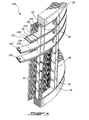
Figure 1 is a perspective view of a demountable screen basket according to a first embodiment; -
Figure 2 is a perspective partly sectional view ofFigure 1 ; -
Figures 3A to 3C are top-plan cross-sections illustrating back contours for the locking portions and for the corresponding complementary grooves of the support ring assemblies of screen baskets according to first, second and third embodiments; -
Figure 4 is a perspective partly sectional view of a screen basket according to a fourth embodiment; -
Figure 5 is an exploded view of the ring assembly fromFigure 4 ; -
Figure 6 is a perspective partly sectional view of a screen basket according to a fifth embodiment; -
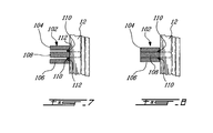
Figure 7 is an isolated radial cross-sections of the assembly of a profiled bar and a support ring assembly of the screen basket ofFigure 6 , illustrating the compressible inserts before being compressed; -
Figure 8 is an isolated radial cross-sections of the assembly of a profiled bar and a support ring assembly of the screen basket ofFigure 6 , illustrating the compressible inserts compressed; -
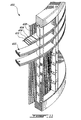
Figure 9 is a perspective partly sectional view of a screen basket according to a sixth embodiment; -
Figure 10 is a perspective partly sectional view of a screen basket according to an seventh embodiment; -
Figure 11 is a perspective partly sectional view of a screen basket according to an eight embodiment; -
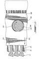
Figure 12 is a sectional top plan view of a mounting mechanism used to mount the profiled bars to the support ring assembly; the mounting mechanism being illustrating in a non tensioning position; -
Figure 13 is a sectional top plan view of the mounting mechanism ofFigure 12 illustrated in a tensioning position; -
Figure 14 is a sectional side elevational view of an alternative mounting mechanism used to mount the profiled bars to the support ring assembly; the mounting mechanism being illustrating in a non tensioning position; and -
Figure 15 is a sectional side elevational view of the alternative mounting mechanism ofFigure 14 illustrated in a tensioning position. - Generally stated, according to illustrative embodiments, there is provided a screen basket including profiled bars evenly spaced circumferentially to form a plurality of continuous slots that covers the whole basket length. The profiled bars are fixed in place by support rings which formed a backing structure for the profiled bars. The support rings and/or the groove disk(s) are made of at least two sections.
- In the following description, similar features in the drawings have been given similar reference numerals, and in order not to weigh down the figures, some elements are not referred to in some figures if they were already identified in a precedent figure.
- Turning now to
Figures 1-2 of the appended drawings, ascreen basket 10 according to a first embodiment will be described. - The
demountable screen basket 10 comprises a plurality of profiledbars 12 aligned along alongitudinal axis 14 and positioned so as to define a slottedcylindrical wall 15 having aninner side 16, defining a screening surface, and anouter side 18. The profiledbars 12 extend between twolongitudinal ends 20. Thebasket 10 also includes a plurality ofsupport ring assemblies 22 mounted to the plurality of profiledbars 12, transversally therefrom, for assembling the plurality of profiledbars 12 into the slottedcylindrical wall 15, a pair ofannular end flanges 24, and a plurality ofclamping posts 26 for positioning and contributing to securing thesupport ring assemblies 22. - As can be better seen from
Figure 2 , each profiledbar 12 has adovetail portion 28 configured to be mounted to thesupport ring assemblies 22 as will be described hereinbelow. - Each
support ring assembly 22 includes a topsectional support ring 30 and a bottomsectional support ring 32. Bothsupport rings grooves 34 complementary to thedovetail portion 28 of the profiledbars 12. Accordingly, the profiledbars 12 are prevented from being released radially. Each profiledbar 12 is however slidable along the support ring assemblies 22 and therefore removably mounted thereto. Indeed, to ease the mounting of the profiledbars 12 into thegrooves 34, thedovetail portions 28 andgrooves 34 are so dimensioned as to yield a clearance therebetween. - The
grooves 34 are located on the inner side diameter of therings screen basket 10. For inward flow screen basket configuration (not illustrated), thegrooves 34 are located on the outer side diameter of therings clamping posts 26 are positioned on the inner side of the basket. - It should be noted that the
rings assembly grooves 34. - As mentioned hereinabove, the top and
bottom rings ring ring sections 36, 36'. Of course, the number of ring sections may vary. - The
rings sections 36 or 36'. - To press the stack of support rings 30, 32, each pair of rings are clamped together for example at equally spaced circumferential locations by the clamping posts 26. The clamping posts 26 are in the form of combs provided with
longitudinal notches 40 for receiving the pair of rings 30-32. - Even though the clamping combs 26 are illustrated as V or U-shaped elongated members, they can also be tubular for example. The clamping combs 26 can further be in the form of elongated beam-like members provided with V-shaped brackets (not shown) mounted thereon for receiving the
support ring assemblies 22. - The
notches 40 are distributed to locate thesupport ring assemblies 22 at desired locations along the basket length with uniform or variable spacing, to have for example tighter ring pair spacing in a more critical region of thebasket 10. - More specifically, the
support ring assemblies 22 are provided with respectiveco-axial holes 38 receiving therods 42. - Still referring to
Figure 2 , thebasket 10 also includes end rings 52 that are mounted at each of the longitudinal end of the clamping combs 26 so as to abut theflanges 24. Eachend ring 52 is a grooved ring contacting thecombs 26 - The
rods 42 are inserted intoholes 38 in the top and bottom rings 52. - The bottom rings 52 also include fastener's holes (not shown) to allow a threaded fastener to enter a threaded aperture (not shown) of the
flange 24. - Also, the clamping combs 26 can alternatively be positioned so as to show an angle with both the
support ring assemblies 22 and the profiled bars 12 and are thus not limited to the position aligned with the profiled bars 12 illustrated for example inFigures 1-2 . - Even though the
basket 10 is illustrated with equally distanced clamping combs 26, it can be provided with unequally spaced clamping combs 26. - Also, the number of profiled
bars 12,support ring assemblies 22, and clamping combs 26 may vary. - Furthermore, even though the
screen basket 10 has been described as a screen suitable for outward flow, it is believed to be within the reach of a person skilled in the art to adapt the present teaching for an inward flow application. For example, in such a case, thesupport ring assemblies 22, the end rings 52 and the clamping combs 26 are positioned on the inner side of the cylinder formed by the profiled bars 12, with the profiled portions thereof located on the outside of the cylinder. - It is also to be noted that the clamping combs 26 could be replaced by spacer blocks (not shown), that would be used to determine the axial separation between the
support ring assemblies 22. - As will be illustrated hereinbelow, other securing means than the clamping combs 26 can also be used to assemble the profiled
bars 12 to therings - Even though the
basket 10 has been described equipped with profiledbars 12 having a dovetail portion configured to be mounted to the support ring assemblies 22 (seeFigure 3A for example), it is not limited to such shape. - For example,
Figure 3B illustrates profiledbars 56 according to a second embodiment including lockingportions 58 having a tapered shape. The support rings 60 have acomplementary portion 62 which allows easy insertion of the locking portion therein. -
Figure 3C illustrates profiledbars 64 according to a third embodiment, including straight mountingportions 66. The support rings 68 according to this third illustrative embodiment have a complementary rectangular-shaped receivingportion 70. According to this third embodiment, the profiled bars 64 and support rings 68 are further assembled using glue, welding, brazing or other equivalent methods. - Turning now to
Figure 4 ascreen basket 80 according to a fourth embodiment will now be described. Since thescreen basket 80 is similar to thescreen basket 10, and for concision purposes, only the differences between the two screen baskets will be described herein. - The
screen basket 80 comprises a plurality of profiledbars 12 positioned so as to define a slottedcylindrical wall 15. The profiled bars 12 extend between two longitudinal ends 20. Thebasket 80 also includes a plurality ofsupport ring assemblies 82 mounted to the plurality of profiledbars 12, transversally therefrom, for assembling the plurality of profiledbars 12 into the slottedcylindrical wall 15. - Turning now briefly to
Figure 5 , eachsupport ring assembly 82 includes a pair of sectional rings 84. Each of the sectional rings 84 is assembled from a plurality of ring sections 86 (four illustrated for each ring 84). Thering sections 86 may have the same arc length, for example to simplify the manufacturing process of thesupport ring 84. Of course, the number of ring sections may vary. - The support rings 84 are provided with identical equi-distanced
grooves 88 complementary to thedovetail portion 28 of the profiled bars 12. - It should be noted that the
rings 84 are manufactured before assembly and already include theassembly grooves 88. According to this fourth embodiment, thering sections 86 are permanently secured end-to-end using glue or welding. According to further embodiments (not shown), thering sections 86 are assembled using fasteners. A combination of fastening methods can also be used. - The plurality of profiled
bars 12 are also permanently secured to the support rings 84 using glue, welding or brazing, no other securing means being used to assemble thebasket 80. However, as a person skilled in the art would now appreciate, eachring assembly 82 needs not to be secured to each profiledbar 12 to yield abasket 80 having sufficient rigidity in most applications. - Contrarily to the
ring sections 36 and 36' of thering assembly 22 according to the first illustrative embodiment, the tworings 84 can be assembled so that theirrespective sections 86 are aligned. Moreover, when therings 84 are secured for example by welding to the profiled bars 12, asingle ring 84 perring assembly 82 can be used. - Turning now to
Figures 6 to 8 of the appended drawings, abasket 100 according to a fifth embodiment will be described. Since thescreen basket 100 is very similar to thescreen basket 10, and for concision purposes, only the differences between thebaskets - Generally stated, the main difference between the two
baskets support ring assemblies 102 of thescreen basket 100 which differ from thesupport ring assemblies 22 of thescreen basket 10. The means for securing thesupport ring assemblies 102 also differ. - Each
support ring assembly 102 includes top and bottom sectional rings 104, 106 which extend along the periphery of thebasket 100. The top and bottom sectional rings 104 and 106 are each made of at least two angular segments. Thesupport ring assembly 102 also includes an intermediate sectionalgrooved disk 108, which is made of at least two angular segments, mounted between the top and bottom sectional rings 104 and 106. The intermediatesectional groove disk 108 is similar to thegroove disks Figure 2 . - The
grooved disk 108 includesgrooves 34 for complementary receiving thedovetail portions 28 of the profiled bars 12 as discussed hereinbelow in more detail. - The
support ring assembly 102 further comprises two compressible inserts in the form ofrings 110 positioned between arespective support ring grooved disk 108 adjacent to the profiled bars 12. The inner side of eachsupport ring chamfer 112 for biasing theinserts 110 towards profiledbars 12 when thesupport ring assembly 102 is compressed as illustrated inFigures 7 and 8 . Also, as illustrated inFigures 7 and 8 , thesupport ring assembly 102 allows forcing the dovetail portion of thebars 12 towards thegrooves 34, providing a locking effect. This locking effect is discussed in aPCT patent application no. WO 2006/119614, published on November 16, 2006 and entitled Screen Basket with Replaceable Profiled Bars. - It has been found that any elastomeric material having a Young's modulus lower than about 20 GPa is suitable to be used as the
inserts 110. - Of course, the support rings 104, 106 and the intermediate
grooved disk 108 are provided withholes 114 to allow therods 42 therethrough. To provide better stability, theholes 114 are positioned so that each section of the support rings 104, 106 and of theintermediate groove disk 108 include at least onesuch hole 114 and therefore receives at least onerod 42. It is to be noted that the joints of the two support rings 104, 106 and of theintermediate groove disk 108 forming onesupport ring assembly 102 are offset to improve the structural integrity of thesupport ring assembly 102. - The number of sections forming the segmented support rings 104 and 106 and the segmented
grooved disk 108 may of course vary. Typically, six angular segments are used for each element. - Turning now to
Figure 9 of the appended drawings, ascreen basket 200 according to a sixth embodiment will now be described. For concision purpose, and since thescreen basket 200 is similar to thescreen basket 100 described hereinabove, only the differences between these screen baskets will be described hereinbelow. - Generally stated, the main difference between the
screen basket 200 and thescreen basket 100 concerns thesupport ring assembly 202. Thisassembly 202 includes two segmentedintermediate groove disks segmented support disks - The other features and the operation of the
screen basket 200 are similar to thescreen basket 100. - Turning now to
Figure 10 of the appended drawings, ascreen basket 300 according to a seventh embodiment will be described. For concision purpose, and since thescreen basket 300 is similar to thescreen baskets - Generally stated, the main difference between the
screen basket 300 and thescreen basket 200 concerns thesupport ring assembly 302. Thisassembly 302 includes two segmentedintermediate groove disks bottom support disk 308 and a non-segmentedtop support disk 310. - Of course, one skilled in the art will understand that, in a non-illustrated embodiment, the bottom support disk could be non-segmented and the top support disk could be segmented.
- The other features and the operation of the
screen basket 300 are similar to thescreen basket 100. - Turning now to
Figure 11 of the appended drawings, ascreen basket 400 according to an eight embodiment will be described. For concision purpose, and since thescreen basket 400 is similar to thescreen baskets - Generally stated, the main difference between the
screen basket 400 and thescreen basket 300 concerns thesupport ring assembly 402. Thisassembly 402 includes two segmentedintermediate groove disks 404 and 406 sandwiched between twonon-segmented support disks - The other features and the operation of the
screen basket 400 are similar to thescreen basket 100. - Turning now to
Figures 12 and13 of the appended drawings, a method and mechanism to releasably mount the profiledbars 12 to the clamping combs 26 will be described. It is to be noted that this method and mechanism could be used with any of the embodiments described hereinabove which includes clamping combs 26 or similar mechanisms and with non-illustrated embodiments mixing features of the described embodiments. - Generally stated, the mounting mechanism uses a cam action to maintain the
dovetail portion 28 of the profiled bars 12 on thegrooves 34 of thegrooved disk 502. - Accordingly the mounting
rod 504, which corresponds to the mountingrod 42 ofFigure 2 , has an oval shape and theapertures 506 of thesupport disk 508 are generally D-shaped. -
Figure 12 illustrates this assembly in a non-tensioning position. In this position, the greater diameter of therod 504 is aligned with the flat portion of the hole. - When the
rod 504 is rotated (seearrow 510 inFigure 13 ), theoval rod 504 contacts theflat portion 512 of theaperture 506 to radially displace the support disk (see arrows 514) and therefore force the contact between thedovetail portions 28 and the shapedgrooves 34. Accordingly, thebars 12 are maintained to thesupport disks 508 while therod 504 is in the tensioning position illustrated inFigure 10 . It is to be noted that the dashed lines ofFigure 13 illustrate the initial position of thesupport disk 508 and of thebars 12. - Turning now to
Figures 14 and 15 of the appended drawings, another method and mechanism to releasably mount the profiledbars 12 to the clamping combs 26 will be described. It is to be noted that this method and mechanism could be used with any of the illustrative embodiments described hereinabove which includes clamping combs 26 or similar mechanisms and with non-illustrated embodiments mixing features of the described embodiments. - Generally stated, the mounting mechanism illustrated in
Figures 14 and 15 uses a cam action to maintain thedovetail portion 28 of the profiled bars 12 on thegrooves 34 of thegrooved disk Figures 12 and13 where it is the rod that is not circular, thepins 612 used are circular and are inserted inapertures 614 of the pushingdisks apertures 616 of thegroove disks - Accordingly, when the round pins 612 are inserted in the apertures (see
Figure 15 ) theapertures 614 are forced into alignment with theapertures 616 thereby radially moving the pushingdisks 608 and 610 (see arrows 618) to again forcing the contact between thedovetail portions 28 and the shapedgrooves 34. - It is to be noted that the
pins 612 have a light chamfer to ease their insertion in theapertures pins 612 could be tapered (not shown). - According to still a further embodiment, rods or combs or any other equivalent means are used to force the
dovetail portions 28 of the profiled bars 12 into thegrooves 34 while the sections 36-36' or the rings are assembled using welding, gluing or brazing for example. - The above described screen baskets can be used in a screening apparatus either held fixed or put in constant or intermittent rotation along an axis, or put under constant or intermittent vibration or displacement.
- The profiled bars, support ring assemblies and support can be made to conform to any shape or contour and clamping posts so configured and sized as to yield a screening surface which is flat, curved, stepped, conical, etc.
Claims (6)
- A screen basket comprising:a plurality of profiled bars (12, 56, 64) generally aligned along a longitudinal axis so as to define a slotted cylindrical wall (15) having an inner side and an outer side extending between two longitudinal ends; each of the profiled bars (12, 56, 64) having a radial profiled portion and a radial locking portion (28, 58, 70); anda plurality of support ring assemblies (22, 102, 202, 302, 402), comprising respective first support rings (30, 32, 104, 106), each mounted to at least some of the plurality of profiled bars substantially transversally therefrom, for assembling the plurality of profiled bars (12, 56, 64) into the slotted cylindrical wall; each of the plurality of first support rings (30, 32) including a plurality of grooves (34); each of the plurality of grooves (34) being configured and sized for complementary receiving the radial locking portion (28, 58, 70) of a respective one of the profiled bars; characterized in that the plurality of first support rings are assembled from a plurality of sections; and at least one of the support ring assemblies further includes a movable support or pushing disk (508, 608), the disk having an aperture (506, 614) therein, and a rod (504) or pin (612) arranged to be inserted into the aperture and to move the movable disk to force contact between the locking portions and the grooves.
- A screen basket as recited in claim 1, wherein the plurality of sections of each of the first support rings (30, 32) are assembled using fastening means selected from the group consisting of welding, gluing and fasteners.
- A screen basket as recited in claim 1 or claim 2, further comprising a plurality of second support rings (30, 32, 104, 106); each one of the plurality of second support rings being mounted to a corresponding one of the plurality of first support rings in a stacked relationship so as to define together one of thesupport ring assemblies.
- A screen basket as recited in claim 3, wherein each of the second support rings is configured and sized for complementary receiving the radial locking portion of a respective one of the profiled bars and being mounted to at least some of the plurality of profiled bars substantially transversally therefrom.
- A screen basket as recited in claim 3 or claim 4, further comprising top and bottom flanges (24), each mounted to a respective one of the two longitudinal ends of the slotted cylindrical wall (15); the support ring assemblies (22, 102, 202, 302, 402) being secured to the plurality of profiled bars using a plurality of combs (26) spaced around the slotted cylindrical wall (15); each of the plurality of combs being further for longitudinally positioning the support ring assemblies along the slotted cylindrical wall; the combs being secured to both top and bottom flanges (24) therebetween and including longitudinal notches (40) to receive the support ring assemblies.
- A screen basket as recited in claim 5, wherein the clamping combs are secured to the top and bottom flanges via the rod (42, 504); the first and second support rings being provided with holes to receive the the rod.
Applications Claiming Priority (2)
| Application Number | Priority Date | Filing Date | Title |
|---|---|---|---|
| US98781807P | 2007-11-14 | 2007-11-14 | |
| PCT/CA2008/001882 WO2009062287A1 (en) | 2007-11-14 | 2008-10-24 | Screen basket |
Publications (3)
| Publication Number | Publication Date |
|---|---|
| EP2222916A1 EP2222916A1 (en) | 2010-09-01 |
| EP2222916A4 EP2222916A4 (en) | 2014-06-25 |
| EP2222916B1 true EP2222916B1 (en) | 2015-06-24 |
Family
ID=40638276
Family Applications (1)
| Application Number | Title | Priority Date | Filing Date |
|---|---|---|---|
| EP08850348.7A Active EP2222916B1 (en) | 2007-11-14 | 2008-10-24 | Screen basket |
Country Status (8)
| Country | Link |
|---|---|
| US (1) | US8297445B2 (en) |
| EP (1) | EP2222916B1 (en) |
| JP (1) | JP5465181B2 (en) |
| CN (1) | CN101910509B (en) |
| BR (1) | BRPI0819362B1 (en) |
| CA (1) | CA2705475C (en) |
| MX (1) | MX2010005202A (en) |
| WO (1) | WO2009062287A1 (en) |
Families Citing this family (15)
| Publication number | Priority date | Publication date | Assignee | Title |
|---|---|---|---|---|
| CA2609881C (en) | 2005-05-09 | 2012-05-29 | Marc-Andre Hetu | Screen basket with replaceable profiled bars |
| CA2705475C (en) | 2007-11-14 | 2015-05-05 | Filtration Fibrewall Inc. | Screen basket |
| DE102014209200B3 (en) * | 2014-05-15 | 2015-04-09 | Voith Patent Gmbh | Method for producing a screening device |
| JP6460741B2 (en) * | 2014-08-06 | 2019-01-30 | 相川鉄工株式会社 | Papermaking strainer and papermaking foreign matter separating device |
| CN106079209B (en) * | 2016-06-06 | 2019-06-25 | 北京斯克瑞科技有限公司 | A kind of polyurethane basket and its forming method |
| CN109641240B (en) * | 2016-08-30 | 2022-04-01 | 施玛克投资私人有限公司 | Wire member and method of manufacturing wire member |
| CN107142771A (en) * | 2017-05-31 | 2017-09-08 | 瑞安市金邦喷淋技术有限公司 | The screen cylinder of paper machine |
| CN107142770A (en) * | 2017-05-31 | 2017-09-08 | 瑞安市金邦喷淋技术有限公司 | The ring flange of paper machine screen cylinder and the attachment structure of diversion screen rod |
| CN109453551A (en) * | 2017-09-06 | 2019-03-12 | 欧盛腾集团有限公司 | Sieve bend |
| US10411448B1 (en) * | 2018-08-20 | 2019-09-10 | Siemens Industry, Inc. | Ring assembly of radially-concentric rings with quick fastening mechanism to detachably connect such rings to one another |
| DE102018007294A1 (en) * | 2018-09-14 | 2020-03-19 | Guntram Krettek | Process for fixing a sheet and filter device produced therewith |
| DE102019107261B3 (en) * | 2019-03-21 | 2020-03-26 | Voith Patent Gmbh | SCREENING PROCESS |
| DE102019107693A1 (en) * | 2019-03-26 | 2020-10-01 | Voith Patent Gmbh | Pressure sorter |
| CN110387762B (en) * | 2019-07-29 | 2024-11-12 | 欧佩德伺服电机节能系统有限公司 | Screen bars, screen drums and pressure screens |
| CN115848779B (en) * | 2023-01-30 | 2024-12-10 | 花园新材料股份有限公司 | A light paper basket |
Citations (4)
| Publication number | Priority date | Publication date | Assignee | Title |
|---|---|---|---|---|
| US2167910A (en) | 1936-11-06 | 1939-08-01 | Rottenburg Henry | Threaded and other bolts, pins, and the like |
| US3604298A (en) | 1969-07-07 | 1971-09-14 | Chester Dekiel | Die set for punch press having adjustable die aligning means |
| DE10247166A1 (en) | 2002-10-10 | 2004-04-22 | Voith Paper Patent Gmbh | Process to make paper sorting sieve with three parallel rods separated by narrow gap and transposed and tensioned in position prior to welding |
| WO2006119614A1 (en) | 2005-05-09 | 2006-11-16 | Hetu Marc-Andre | Screen basket with replaceable profiled bars |
Family Cites Families (91)
| Publication number | Priority date | Publication date | Assignee | Title |
|---|---|---|---|---|
| US689934A (en) | 1901-09-28 | 1901-12-31 | Nathaniel L Vrooman | Paper-pulp strainer. |
| US703682A (en) | 1902-02-18 | 1902-07-01 | Nathaniel L Vrooman | Paper-pulp strainer. |
| US2065263A (en) | 1932-03-22 | 1936-12-22 | Beldam William Robert | Filtering or straining apparatus |
| SE304439B (en) | 1962-09-28 | 1968-09-23 | Ekstroemsmaskinaffaer A Ab | |
| US3515281A (en) | 1968-05-09 | 1970-06-02 | Improved Machinery Inc | Backing wire for rotary drum filters |
| US3837499A (en) | 1971-03-29 | 1974-09-24 | Improved Machinery Inc | Drum structure for rotary drum filtering apparatus |
| US3962091A (en) | 1973-01-04 | 1976-06-08 | Dorr-Oliver Incorporated | Rotary drum filter with wire deck, apparatus and method |
| GB1472547A (en) | 1973-12-11 | 1977-05-04 | Bekaert Sa Nv | Wire screens |
| US4002540A (en) | 1974-08-09 | 1977-01-11 | Hendrick Manufacturing Company | Screen having parallel slots |
| GB2033242A (en) | 1978-10-20 | 1980-05-21 | Greening N Ltd | Screening Apparatus |
| US4410424A (en) | 1980-05-02 | 1983-10-18 | The Black Clawson Company | Screening apparatus for paper making stock |
| WO1988009843A1 (en) | 1987-06-11 | 1988-12-15 | A. Ahlstrom Corporation | Pulp screening apparatus |
| FR2572950B1 (en) | 1984-11-12 | 1987-01-23 | Lamort E & M | IMPROVEMENTS ON SCREENS FOR CLEANERS AND THEIR MANUFACTURE |
| US4855038A (en) | 1985-06-20 | 1989-08-08 | Beloit Corporation | High consistency pressure screen and method of separating accepts and rejects |
| JPS62156493A (en) | 1985-12-27 | 1987-07-11 | 永岡金網株式会社 | Double cylinder screen |
| FR2612081B1 (en) | 1987-03-13 | 1991-02-08 | Lamort E & M | IMPROVEMENT IN SCREENS FOR PURIFIER AND THEIR MANUFACTURE |
| DE3816152A1 (en) | 1987-11-14 | 1989-11-23 | Voith Gmbh J M | SCREEN BASKET AND METHOD FOR THE PRODUCTION THEREOF |
| US5285560A (en) | 1988-06-10 | 1994-02-15 | Beloit Technologies, Inc. | Method for repairing a screen plate assembly |
| US4822488A (en) | 1988-10-19 | 1989-04-18 | Lavalley Industries, Inc. | Vacuum discharge assembly for rotary drum filters |
| FI80736B (en) | 1989-02-16 | 1990-03-30 | Tampella Oy Ab | FOERFARANDE FOER SORTERING AV MASSASUSPENSION OCH SORTERINGSAPPARAT. |
| US4986900A (en) | 1989-04-04 | 1991-01-22 | A. Ahlstrom Corporation | Sectional screen cylinder |
| DE3927748C2 (en) | 1989-08-23 | 1994-03-10 | Voith Gmbh J M | Process for producing a screen basket and screen basket produced according to this method |
| DE3942591A1 (en) | 1989-12-22 | 1991-06-27 | Voith Gmbh J M | Fibre suspension sorting sieve body - has carrier rings with grooves to hold the sieve rods for strength with simple assembly |
| US5139154A (en) | 1989-12-27 | 1992-08-18 | Beloit Corporation | Wear screen plate and method of manufacture thereof |
| US5061370A (en) | 1990-03-20 | 1991-10-29 | Quebec And Ontario Paper Company Ltd. | Screening device for slurries with improved rotor and hub design |
| US5200072A (en) | 1990-08-16 | 1993-04-06 | Ahlstrom Screen Plates Inc. | Screen plates and methods of manufacture |
| DE4121897A1 (en) * | 1991-07-02 | 1993-01-07 | Fiedler Heinrich Gmbh | SCREEN ELEMENT |
| DE4121896A1 (en) | 1991-07-02 | 1993-01-07 | Fiedler Heinrich Gmbh | SCREEN ELEMENT |
| US5221437A (en) | 1991-07-08 | 1993-06-22 | The Black Clawson Company | Screening apparatus for paper making stock |
| DE4224727A1 (en) | 1992-07-27 | 1994-02-03 | Voith Gmbh J M | Sieve basket for processing suspensions and pulps, e.g. in paper making - has pressure welded mounting points for the rings at the sieve rods for min. blockage |
| SE501110C2 (en) | 1993-04-21 | 1994-11-14 | Kvaerner Pulping Tech | Screening means with a screen body and method and apparatus for the screen body manufacture |
| US5387340A (en) | 1993-07-15 | 1995-02-07 | Ackerman; Carl D. | Wire filter element and method of manufacture |
| US5394600A (en) | 1994-02-14 | 1995-03-07 | Chen; Chao-Ho | Method for making a screen |
| US5611925A (en) | 1994-03-23 | 1997-03-18 | Filtration Systems, Inc. | Hub ring and supporting plate for a filter and methods for manufacturing these members |
| US5513757A (en) | 1994-06-02 | 1996-05-07 | Sulzer Papertec Mansfield Inc. | Continuous cut slotted screen basket |
| FI96701B (en) | 1994-09-27 | 1996-04-30 | Tampella Oy Valmet | Process for making screen cylinder and screen cylinder |
| FR2725737B1 (en) | 1994-10-14 | 1997-01-31 | Lamort E & M | IMPROVEMENTS ON PURIFICATION SIEVES, ESPECIALLY FOR PAPER PULP |
| JP2968696B2 (en) | 1994-12-28 | 1999-10-25 | 相川鉄工株式会社 | Method of manufacturing screen plate for papermaking and screen plate for papermaking |
| JPH08209574A (en) | 1995-01-27 | 1996-08-13 | Aikawa Iron Works Co Ltd | Screen plate for papermaking |
| US5823355A (en) | 1995-03-29 | 1998-10-20 | Beloit Technologies, Inc. | Fibresaver screen basket support |
| US5718826A (en) | 1995-05-26 | 1998-02-17 | Cae Screen Plates, Inc. | Screen and method of manufacture |
| FI960438A7 (en) | 1995-09-11 | 1997-03-12 | Ahlstrom Machinery Oy | Apparatus and method for cleaning a pulp washer from sticky substances |
| JP3190234B2 (en) | 1995-09-21 | 2001-07-23 | 相川鉄工株式会社 | Papermaking screen |
| FI100344B (en) | 1995-11-28 | 1997-11-14 | Ahlstrom Machinery Oy | Process for making a sieve product and sieve product |
| US5791495A (en) | 1996-03-11 | 1998-08-11 | Beloit Technologies, Inc. | Paper pulp screen cylinder |
| ATE210756T1 (en) | 1996-05-24 | 2001-12-15 | Voith Sulzer Stoffaufbereitung | METHOD FOR PRODUCING A SCREENING DEVICE WITH GAP-SHAPED OPENINGS AND SCREENING DEVICE PRODUCED THEREFROM |
| JP3190254B2 (en) | 1996-06-20 | 2001-07-23 | 相川鉄工株式会社 | Screen for papermaking |
| US5799798A (en) | 1996-08-23 | 1998-09-01 | Chen; Chao-Ho | Screen cylinder for screening high consistency pulp |
| DE19635189C2 (en) | 1996-08-30 | 1999-01-28 | Voith Sulzer Stoffaufbereitung | Process for the production of sieves |
| US7188733B2 (en) | 1996-10-03 | 2007-03-13 | Advanced Fiber Technologies (Aft) Trust | Screening device, such as a screen cylinder, and method of manufacture of the screening device |
| US20020130075A1 (en) | 1999-08-19 | 2002-09-19 | Cae Screenplates Oy | Screening device, such as a screen cylinder, and method of manufacture of the screening device |
| CN1080350C (en) | 1996-10-03 | 2002-03-06 | Cae筛板公司 | Screening device, such as screen cylinder, and method of manufacture of screen device |
| DE19651643A1 (en) | 1996-12-12 | 1998-06-18 | Voith Sulzer Stoffaufbereitung | Sieve for sorting out suspended fibres |
| US5798025A (en) | 1997-03-13 | 1998-08-25 | Ishikawajima-Harima Jukogyo Kabushiki Kaisha | Apparatus for screening waste paper pulp |
| US6131743A (en) | 1997-06-18 | 2000-10-17 | Hermann Finckh Maschinenfabrik Gmbh & Co. | Screen basket for fiber suspensions and method for the production thereof |
| US5954956A (en) | 1997-07-22 | 1999-09-21 | J&L Fiber Services | Modular screen cylinder and a method for its manufacture |
| FI103208B (en) | 1997-10-29 | 1999-05-14 | Valmet Corp | A method of making a screen cylinder and a screen cylinder |
| JP3286592B2 (en) | 1997-12-25 | 2002-05-27 | 相川鉄工株式会社 | Screening equipment for papermaking |
| SE515006C2 (en) | 1998-01-29 | 2001-05-28 | Gl & V Celleco Ab | Cylindrical screen and method of producing a cylindrical screen with formed projections |
| US6138838A (en) | 1998-05-29 | 2000-10-31 | J&L Fiber Services, Inc. | Screen media and a screening passage therefore |
| US6109452A (en) * | 1998-06-04 | 2000-08-29 | Baker Hughes Incorporated | Centrifuge with partial wear resistant basket |
| US5968357A (en) | 1998-08-27 | 1999-10-19 | Voith Sulzer Paper Technology North America, Inc. | Screen basket having a removable and replaceable cylindrical mesh liner |
| DE19842042A1 (en) | 1998-09-14 | 2000-03-23 | Fiedler Heinrich Gmbh | Sieve assembly for fiber suspensions to give papermaking pulp has an exchangeable sieve unit clamped to the reinforcement structure so that components which are not worn can be used again |
| WO2000065151A1 (en) | 1999-04-27 | 2000-11-02 | Cae Screenplates, Inc. | Edge wire contour with enhanced functionality |
| SE515902C2 (en) | 1999-05-26 | 2001-10-29 | Kvaerner Pulping Tech | Screen cylinder for screw press and method for manufacturing the screen cylinder |
| FR2794478B1 (en) | 1999-06-04 | 2001-08-03 | Lamort E & M | CYLINDRICAL SIEVES, ESPECIALLY FOR PAPER PULP |
| US7125491B2 (en) | 2000-02-03 | 2006-10-24 | Andritz Ag | Screen and process for manufacturing a screen of this kind |
| JP3396456B2 (en) | 2000-02-04 | 2003-04-14 | 三菱重工業株式会社 | Stock selection equipment |
| CA2403127A1 (en) | 2000-02-19 | 2002-10-11 | Voith Finckh Fiber Systems Gmbh & Co. Kg | Sieve for fibre suspensions and a method for producing same |
| US6491168B1 (en) | 2000-04-23 | 2002-12-10 | J + L Fiber Services, Inc. | Pulp screen basket |
| FR2809029B1 (en) | 2000-05-16 | 2002-06-21 | Johnson Filtration Systems | METHOD FOR MANUFACTURING A MECHANICAL FILTRATION BASKET |
| JP2001347108A (en) | 2000-06-06 | 2001-12-18 | Aikawa Iron Works Co Ltd | Method of forming cylindrical screen and ring piece |
| US6649068B2 (en) | 2000-06-14 | 2003-11-18 | Andritz Inc. | Filtration of pulp mill liquids |
| DE10052715A1 (en) | 2000-10-24 | 2002-05-02 | Fiedler Heinrich Gmbh | slotted screen |
| CA2444486C (en) | 2001-04-16 | 2013-04-02 | J & L Fiber Services, Inc. | Screen cylinder and method |
| SE519079C2 (en) | 2001-05-30 | 2003-01-07 | Metso Paper Inc | Screen for screening pulp suspensions including a conical surface support ring |
| JP2003010608A (en) | 2001-07-05 | 2003-01-14 | Aikawa Iron Works Co Ltd | Cylindrical screen |
| GB0120862D0 (en) | 2001-08-29 | 2001-10-17 | United Wire Ltd | Method and device for joining screens |
| US7168570B2 (en) | 2001-10-24 | 2007-01-30 | Advanced Fiber Technologies | Screen cylinder with performance boosting configuration |
| FI119387B (en) | 2003-08-22 | 2008-10-31 | Metso Paper Inc | Process for manufacturing a screen cylinder and screen cylinder |
| SE0303260D0 (en) | 2003-12-04 | 2003-12-04 | Metso Paper Inc | Screening apparatus for screening pulp suspensions with monitoring means |
| US7374050B2 (en) | 2004-04-23 | 2008-05-20 | Andritz Inc. | High capacity and high efficiency filter deck assembly |
| ITVI20040139A1 (en) * | 2004-06-10 | 2004-09-10 | Comer Spa | METHOD FOR THE MANUFACTURE OF FILTER BASKETS IN FIBER SUSPENSION AND FILTER BASKET MANUFACTURED USING THE METHOD |
| FI119440B (en) | 2004-07-16 | 2008-11-14 | Advanced Fiber Tech Aft Trust | Process for manufacturing a screen cylinder and a screen cylinder |
| DE102004057859A1 (en) | 2004-11-30 | 2006-06-01 | Siebtechnik Gmbh | Centrifuge basket comprises an outer conical basket and sieve elements which are fixed to it using clamping members |
| US20070074998A1 (en) | 2005-10-04 | 2007-04-05 | Langner Herbert Gunther Joachi | Method and apparatus for screening kaolin |
| FI122697B (en) | 2005-11-02 | 2012-05-31 | Metso Paper Inc | visibility Cylinder |
| DE102006008172A1 (en) | 2006-02-22 | 2007-08-23 | Voith Patent Gmbh | Producing a screen for use in a papermaking pressure sorter comprises inserting profile bars into peripheral recesses in a curved bar holder and forming the holder into a ring |
| DE102006007660A1 (en) | 2006-02-22 | 2007-08-23 | Voith Patent Gmbh | Producing a screen for use in a papermaking pressure sorter comprises inserting profile bars into peripheral recesses in a bar holder and forming the holder into a ring with the recesses on the inside |
| TW200736458A (en) | 2006-03-24 | 2007-10-01 | Slit And Hole Industry Co Ltd | A sieve (screen) can prevent sieve bars from falling off |
| CA2705475C (en) | 2007-11-14 | 2015-05-05 | Filtration Fibrewall Inc. | Screen basket |
-
2008
- 2008-10-24 CA CA2705475A patent/CA2705475C/en active Active
- 2008-10-24 WO PCT/CA2008/001882 patent/WO2009062287A1/en not_active Ceased
- 2008-10-24 CN CN200880124749XA patent/CN101910509B/en active Active
- 2008-10-24 BR BRPI0819362A patent/BRPI0819362B1/en active IP Right Grant
- 2008-10-24 US US12/734,628 patent/US8297445B2/en active Active
- 2008-10-24 JP JP2010533393A patent/JP5465181B2/en active Active
- 2008-10-24 MX MX2010005202A patent/MX2010005202A/en active IP Right Grant
- 2008-10-24 EP EP08850348.7A patent/EP2222916B1/en active Active
Patent Citations (4)
| Publication number | Priority date | Publication date | Assignee | Title |
|---|---|---|---|---|
| US2167910A (en) | 1936-11-06 | 1939-08-01 | Rottenburg Henry | Threaded and other bolts, pins, and the like |
| US3604298A (en) | 1969-07-07 | 1971-09-14 | Chester Dekiel | Die set for punch press having adjustable die aligning means |
| DE10247166A1 (en) | 2002-10-10 | 2004-04-22 | Voith Paper Patent Gmbh | Process to make paper sorting sieve with three parallel rods separated by narrow gap and transposed and tensioned in position prior to welding |
| WO2006119614A1 (en) | 2005-05-09 | 2006-11-16 | Hetu Marc-Andre | Screen basket with replaceable profiled bars |
Also Published As
| Publication number | Publication date |
|---|---|
| US8297445B2 (en) | 2012-10-30 |
| US20100263819A1 (en) | 2010-10-21 |
| EP2222916A4 (en) | 2014-06-25 |
| MX2010005202A (en) | 2010-11-12 |
| CN101910509B (en) | 2012-08-08 |
| JP5465181B2 (en) | 2014-04-09 |
| BRPI0819362B1 (en) | 2018-12-26 |
| EP2222916A1 (en) | 2010-09-01 |
| CA2705475A1 (en) | 2009-05-22 |
| CA2705475C (en) | 2015-05-05 |
| BRPI0819362A2 (en) | 2015-04-22 |
| CN101910509A (en) | 2010-12-08 |
| WO2009062287A1 (en) | 2009-05-22 |
| JP2011503380A (en) | 2011-01-27 |
Similar Documents
| Publication | Publication Date | Title |
|---|---|---|
| CA2705475C (en) | Screen basket | |
| US8469198B2 (en) | Screen basket with replaceable profiled bars | |
| CA2049279C (en) | Screen plates and methods of manufacture | |
| US6579458B2 (en) | Screening device | |
| PL153440B1 (en) | Rotary shapt assembly, in particular for a disc-type sifter | |
| US6056126A (en) | Screen device with slot-shaped openings | |
| KR101120416B1 (en) | A method of manufacturing a screen cylinder and a screen cylinder | |
| EP2089572B1 (en) | A press roll for washing and/or dewatering pulp, and a method for manufacturing or repairing such a press roll | |
| US9290886B2 (en) | Method of manufacturing a screen cylinder and a screen cylinder | |
| CN114616057B (en) | Screen drum | |
| FI3723916T3 (en) | Screen cylinder | |
| FI119942B (en) | Process for manufacturing a screen cylinder and a screen cylinder | |
| CN112243390A (en) | Method for producing a screen for a tubular screen device and tubular screen device | |
| CA2478566A1 (en) | Screen |
Legal Events
| Date | Code | Title | Description |
|---|---|---|---|
| PUAI | Public reference made under article 153(3) epc to a published international application that has entered the european phase |
Free format text: ORIGINAL CODE: 0009012 |
|
| 17P | Request for examination filed |
Effective date: 20100609 |
|
| AK | Designated contracting states |
Kind code of ref document: A1 Designated state(s): AT BE BG CH CY CZ DE DK EE ES FI FR GB GR HR HU IE IS IT LI LT LU LV MC MT NL NO PL PT RO SE SI SK TR |
|
| AX | Request for extension of the european patent |
Extension state: AL BA MK RS |
|
| DAX | Request for extension of the european patent (deleted) | ||
| RAP1 | Party data changed (applicant data changed or rights of an application transferred) |
Owner name: KADANT CANADA CORP. |
|
| A4 | Supplementary search report drawn up and despatched |
Effective date: 20140523 |
|
| RIC1 | Information provided on ipc code assigned before grant |
Ipc: B07B 1/18 20060101ALI20140519BHEP Ipc: B03B 5/00 20060101ALI20140519BHEP Ipc: D21D 5/16 20060101AFI20140519BHEP |
|
| 17Q | First examination report despatched |
Effective date: 20140606 |
|
| GRAP | Despatch of communication of intention to grant a patent |
Free format text: ORIGINAL CODE: EPIDOSNIGR1 |
|
| GRAS | Grant fee paid |
Free format text: ORIGINAL CODE: EPIDOSNIGR3 |
|
| RIC1 | Information provided on ipc code assigned before grant |
Ipc: B07B 1/18 20060101ALI20150416BHEP Ipc: D21D 5/16 20060101AFI20150416BHEP |
|
| INTG | Intention to grant announced |
Effective date: 20150429 |
|
| GRAA | (expected) grant |
Free format text: ORIGINAL CODE: 0009210 |
|
| AK | Designated contracting states |
Kind code of ref document: B1 Designated state(s): AT BE BG CH CY CZ DE DK EE ES FI FR GB GR HR HU IE IS IT LI LT LU LV MC MT NL NO PL PT RO SE SI SK TR |
|
| REG | Reference to a national code |
Ref country code: GB Ref legal event code: FG4D |
|
| REG | Reference to a national code |
Ref country code: CH Ref legal event code: EP |
|
| REG | Reference to a national code |
Ref country code: AT Ref legal event code: REF Ref document number: 732936 Country of ref document: AT Kind code of ref document: T Effective date: 20150715 |
|
| REG | Reference to a national code |
Ref country code: IE Ref legal event code: FG4D |
|
| REG | Reference to a national code |
Ref country code: DE Ref legal event code: R096 Ref document number: 602008038723 Country of ref document: DE |
|
| REG | Reference to a national code |
Ref country code: SE Ref legal event code: TRGR |
|
| REG | Reference to a national code |
Ref country code: FR Ref legal event code: PLFP Year of fee payment: 8 |
|
| PG25 | Lapsed in a contracting state [announced via postgrant information from national office to epo] |
Ref country code: NO Free format text: LAPSE BECAUSE OF FAILURE TO SUBMIT A TRANSLATION OF THE DESCRIPTION OR TO PAY THE FEE WITHIN THE PRESCRIBED TIME-LIMIT Effective date: 20150924 Ref country code: LT Free format text: LAPSE BECAUSE OF FAILURE TO SUBMIT A TRANSLATION OF THE DESCRIPTION OR TO PAY THE FEE WITHIN THE PRESCRIBED TIME-LIMIT Effective date: 20150624 Ref country code: HR Free format text: LAPSE BECAUSE OF FAILURE TO SUBMIT A TRANSLATION OF THE DESCRIPTION OR TO PAY THE FEE WITHIN THE PRESCRIBED TIME-LIMIT Effective date: 20150624 |
|
| REG | Reference to a national code |
Ref country code: LT Ref legal event code: MG4D |
|
| PG25 | Lapsed in a contracting state [announced via postgrant information from national office to epo] |
Ref country code: LV Free format text: LAPSE BECAUSE OF FAILURE TO SUBMIT A TRANSLATION OF THE DESCRIPTION OR TO PAY THE FEE WITHIN THE PRESCRIBED TIME-LIMIT Effective date: 20150624 Ref country code: GR Free format text: LAPSE BECAUSE OF FAILURE TO SUBMIT A TRANSLATION OF THE DESCRIPTION OR TO PAY THE FEE WITHIN THE PRESCRIBED TIME-LIMIT Effective date: 20150925 Ref country code: BG Free format text: LAPSE BECAUSE OF FAILURE TO SUBMIT A TRANSLATION OF THE DESCRIPTION OR TO PAY THE FEE WITHIN THE PRESCRIBED TIME-LIMIT Effective date: 20150924 |
|
| REG | Reference to a national code |
Ref country code: NL Ref legal event code: MP Effective date: 20150624 |
|
| PG25 | Lapsed in a contracting state [announced via postgrant information from national office to epo] |
Ref country code: EE Free format text: LAPSE BECAUSE OF FAILURE TO SUBMIT A TRANSLATION OF THE DESCRIPTION OR TO PAY THE FEE WITHIN THE PRESCRIBED TIME-LIMIT Effective date: 20150624 |
|
| REG | Reference to a national code |
Ref country code: AT Ref legal event code: UEP Ref document number: 732936 Country of ref document: AT Kind code of ref document: T Effective date: 20150624 |
|
| PG25 | Lapsed in a contracting state [announced via postgrant information from national office to epo] |
Ref country code: PT Free format text: LAPSE BECAUSE OF FAILURE TO SUBMIT A TRANSLATION OF THE DESCRIPTION OR TO PAY THE FEE WITHIN THE PRESCRIBED TIME-LIMIT Effective date: 20151026 Ref country code: SK Free format text: LAPSE BECAUSE OF FAILURE TO SUBMIT A TRANSLATION OF THE DESCRIPTION OR TO PAY THE FEE WITHIN THE PRESCRIBED TIME-LIMIT Effective date: 20150624 Ref country code: CZ Free format text: LAPSE BECAUSE OF FAILURE TO SUBMIT A TRANSLATION OF THE DESCRIPTION OR TO PAY THE FEE WITHIN THE PRESCRIBED TIME-LIMIT Effective date: 20150624 Ref country code: RO Free format text: LAPSE BECAUSE OF NON-PAYMENT OF DUE FEES Effective date: 20150624 Ref country code: IS Free format text: LAPSE BECAUSE OF FAILURE TO SUBMIT A TRANSLATION OF THE DESCRIPTION OR TO PAY THE FEE WITHIN THE PRESCRIBED TIME-LIMIT Effective date: 20151024 Ref country code: ES Free format text: LAPSE BECAUSE OF FAILURE TO SUBMIT A TRANSLATION OF THE DESCRIPTION OR TO PAY THE FEE WITHIN THE PRESCRIBED TIME-LIMIT Effective date: 20150624 Ref country code: PL Free format text: LAPSE BECAUSE OF FAILURE TO SUBMIT A TRANSLATION OF THE DESCRIPTION OR TO PAY THE FEE WITHIN THE PRESCRIBED TIME-LIMIT Effective date: 20150624 |
|
| REG | Reference to a national code |
Ref country code: DE Ref legal event code: R026 Ref document number: 602008038723 Country of ref document: DE |
|
| PLBI | Opposition filed |
Free format text: ORIGINAL CODE: 0009260 |
|
| 26 | Opposition filed |
Opponent name: AIKAWA FIBER TECHNOLOGIES TRUST Effective date: 20160321 |
|
| PLAX | Notice of opposition and request to file observation + time limit sent |
Free format text: ORIGINAL CODE: EPIDOSNOBS2 |
|
| PG25 | Lapsed in a contracting state [announced via postgrant information from national office to epo] |
Ref country code: DK Free format text: LAPSE BECAUSE OF FAILURE TO SUBMIT A TRANSLATION OF THE DESCRIPTION OR TO PAY THE FEE WITHIN THE PRESCRIBED TIME-LIMIT Effective date: 20150624 |
|
| PG25 | Lapsed in a contracting state [announced via postgrant information from national office to epo] |
Ref country code: LU Free format text: LAPSE BECAUSE OF FAILURE TO SUBMIT A TRANSLATION OF THE DESCRIPTION OR TO PAY THE FEE WITHIN THE PRESCRIBED TIME-LIMIT Effective date: 20151024 |
|
| REG | Reference to a national code |
Ref country code: CH Ref legal event code: PL |
|
| PG25 | Lapsed in a contracting state [announced via postgrant information from national office to epo] |
Ref country code: MC Free format text: LAPSE BECAUSE OF FAILURE TO SUBMIT A TRANSLATION OF THE DESCRIPTION OR TO PAY THE FEE WITHIN THE PRESCRIBED TIME-LIMIT Effective date: 20150624 |
|
| REG | Reference to a national code |
Ref country code: IE Ref legal event code: MM4A |
|
| PG25 | Lapsed in a contracting state [announced via postgrant information from national office to epo] |
Ref country code: LI Free format text: LAPSE BECAUSE OF NON-PAYMENT OF DUE FEES Effective date: 20151031 Ref country code: CH Free format text: LAPSE BECAUSE OF NON-PAYMENT OF DUE FEES Effective date: 20151031 |
|
| PG25 | Lapsed in a contracting state [announced via postgrant information from national office to epo] |
Ref country code: SI Free format text: LAPSE BECAUSE OF FAILURE TO SUBMIT A TRANSLATION OF THE DESCRIPTION OR TO PAY THE FEE WITHIN THE PRESCRIBED TIME-LIMIT Effective date: 20150624 |
|
| PLBB | Reply of patent proprietor to notice(s) of opposition received |
Free format text: ORIGINAL CODE: EPIDOSNOBS3 |
|
| REG | Reference to a national code |
Ref country code: FR Ref legal event code: PLFP Year of fee payment: 9 |
|
| PG25 | Lapsed in a contracting state [announced via postgrant information from national office to epo] |
Ref country code: IE Free format text: LAPSE BECAUSE OF NON-PAYMENT OF DUE FEES Effective date: 20151024 |
|
| PG25 | Lapsed in a contracting state [announced via postgrant information from national office to epo] |
Ref country code: BE Free format text: LAPSE BECAUSE OF FAILURE TO SUBMIT A TRANSLATION OF THE DESCRIPTION OR TO PAY THE FEE WITHIN THE PRESCRIBED TIME-LIMIT Effective date: 20150624 |
|
| PG25 | Lapsed in a contracting state [announced via postgrant information from national office to epo] |
Ref country code: HU Free format text: LAPSE BECAUSE OF FAILURE TO SUBMIT A TRANSLATION OF THE DESCRIPTION OR TO PAY THE FEE WITHIN THE PRESCRIBED TIME-LIMIT; INVALID AB INITIO Effective date: 20081024 |
|
| PG25 | Lapsed in a contracting state [announced via postgrant information from national office to epo] |
Ref country code: CY Free format text: LAPSE BECAUSE OF FAILURE TO SUBMIT A TRANSLATION OF THE DESCRIPTION OR TO PAY THE FEE WITHIN THE PRESCRIBED TIME-LIMIT Effective date: 20150624 Ref country code: NL Free format text: LAPSE BECAUSE OF FAILURE TO SUBMIT A TRANSLATION OF THE DESCRIPTION OR TO PAY THE FEE WITHIN THE PRESCRIBED TIME-LIMIT Effective date: 20150624 |
|
| PG25 | Lapsed in a contracting state [announced via postgrant information from national office to epo] |
Ref country code: TR Free format text: LAPSE BECAUSE OF FAILURE TO SUBMIT A TRANSLATION OF THE DESCRIPTION OR TO PAY THE FEE WITHIN THE PRESCRIBED TIME-LIMIT Effective date: 20150624 Ref country code: MT Free format text: LAPSE BECAUSE OF FAILURE TO SUBMIT A TRANSLATION OF THE DESCRIPTION OR TO PAY THE FEE WITHIN THE PRESCRIBED TIME-LIMIT Effective date: 20150624 |
|
| REG | Reference to a national code |
Ref country code: FR Ref legal event code: PLFP Year of fee payment: 10 |
|
| REG | Reference to a national code |
Ref country code: DE Ref legal event code: R100 Ref document number: 602008038723 Country of ref document: DE |
|
| PLCK | Communication despatched that opposition was rejected |
Free format text: ORIGINAL CODE: EPIDOSNREJ1 |
|
| STAA | Information on the status of an ep patent application or granted ep patent |
Free format text: STATUS: THE PATENT HAS BEEN GRANTED |
|
| PLBN | Opposition rejected |
Free format text: ORIGINAL CODE: 0009273 |
|
| STAA | Information on the status of an ep patent application or granted ep patent |
Free format text: STATUS: OPPOSITION REJECTED |
|
| 27O | Opposition rejected |
Effective date: 20180124 |
|
| REG | Reference to a national code |
Ref country code: FR Ref legal event code: PLFP Year of fee payment: 11 |
|
| P01 | Opt-out of the competence of the unified patent court (upc) registered |
Effective date: 20230503 |
|
| PGFP | Annual fee paid to national office [announced via postgrant information from national office to epo] |
Ref country code: FI Payment date: 20250923 Year of fee payment: 18 |
|
| PGFP | Annual fee paid to national office [announced via postgrant information from national office to epo] |
Ref country code: IT Payment date: 20250923 Year of fee payment: 18 |
|
| PGFP | Annual fee paid to national office [announced via postgrant information from national office to epo] |
Ref country code: GB Payment date: 20250923 Year of fee payment: 18 |
|
| PGFP | Annual fee paid to national office [announced via postgrant information from national office to epo] |
Ref country code: FR Payment date: 20250923 Year of fee payment: 18 |
|
| PGFP | Annual fee paid to national office [announced via postgrant information from national office to epo] |
Ref country code: SE Payment date: 20250923 Year of fee payment: 18 |
|
| PGFP | Annual fee paid to national office [announced via postgrant information from national office to epo] |
Ref country code: DE Payment date: 20250923 Year of fee payment: 18 |
|
| PGFP | Annual fee paid to national office [announced via postgrant information from national office to epo] |
Ref country code: AT Payment date: 20250926 Year of fee payment: 18 |