EP2222265B1 - Wheelchair frame and wheelchair with cross-brace - Google Patents
Wheelchair frame and wheelchair with cross-brace Download PDFInfo
- Publication number
- EP2222265B1 EP2222265B1 EP08863436.5A EP08863436A EP2222265B1 EP 2222265 B1 EP2222265 B1 EP 2222265B1 EP 08863436 A EP08863436 A EP 08863436A EP 2222265 B1 EP2222265 B1 EP 2222265B1
- Authority
- EP
- European Patent Office
- Prior art keywords
- cross
- wheelchair
- brace
- frame members
- section
- Prior art date
- Legal status (The legal status is an assumption and is not a legal conclusion. Google has not performed a legal analysis and makes no representation as to the accuracy of the status listed.)
- Active
Links
Images


Classifications
-
- A—HUMAN NECESSITIES
- A61—MEDICAL OR VETERINARY SCIENCE; HYGIENE
- A61G—TRANSPORT, PERSONAL CONVEYANCES OR ACCOMMODATION SPECIALLY ADAPTED FOR PATIENTS OR DISABLED PERSONS; OPERATING TABLES OR CHAIRS; CHAIRS FOR DENTISTRY; FUNERAL DEVICES
- A61G5/00—Chairs or personal conveyances specially adapted for patients or disabled persons, e.g. wheelchairs
- A61G5/02—Chairs or personal conveyances specially adapted for patients or disabled persons, e.g. wheelchairs propelled by the patient or disabled person
-
- A—HUMAN NECESSITIES
- A61—MEDICAL OR VETERINARY SCIENCE; HYGIENE
- A61G—TRANSPORT, PERSONAL CONVEYANCES OR ACCOMMODATION SPECIALLY ADAPTED FOR PATIENTS OR DISABLED PERSONS; OPERATING TABLES OR CHAIRS; CHAIRS FOR DENTISTRY; FUNERAL DEVICES
- A61G5/00—Chairs or personal conveyances specially adapted for patients or disabled persons, e.g. wheelchairs
- A61G5/10—Parts, details or accessories
Definitions
- the invention relates to a wheelchair frame, according to the preamble of claim 1.
- the invention also relates to a wheelchair.
- the Off Carr Fenice has a frame with a backrest that can be folded down and a cross-brace underneath the seat. The rear wheels can be removed, so that the remainder of the wheelchair takes up less space.
- WO 2007/112508 A1 refers to a wheelchair with 3 interchangeable cross-bracing tubes between 2 frame tubes and 1 backrest-stabilizing cross-brace between 2 backrest tubes.
- US 4,858,260 discloses a patient transport apparatus including Trendelenburg mechanism and guard rail. Said apparatus makes usage of a steel channel U-shaped push bar.
- EP 1 155 669 A2 teaches a wheelchair with adjustment of the position of the supporting wheels.
- EP 1 116 480 A1 describes a wheelchair allowing modifications to individual adaptions. Cross-braces in the form of bended bars are depicted.
- a problem of the known wheelchair is that it is difficult to grasp hold of the remainder of the wheelchair after removal of the rear wheels, e.g. when loading it into a car.
- a wheelchair according to the invention comprises a wheelchair frame according to the invention.
- the wheelchair may further include a footrest assembly including left and right members, removably attached to, in particular insertable in, the second legs.
- the wheelchair may also include left and right supports, each attached to a respective one of the first legs and extending transversely to that first leg, and housings, attached to the left and right supports, for removably accommodating rear wheel axles.
- a cross-brace that provides additional support to keep the first legs of the left and right frame members at the intended separation when the occupant is in the wheelchair can be provided with an additional function in that it provides a convenient handle for carrying the wheelchair frame. Because it connects the first legs of the left and right frame members, it is positioned under the seat, and thus relatively close to the centre of gravity of the frame, at least in longitudinal direction (i.e. parallel to the direction of displacement of the wheelchair, in use). It is unlikely to be exactly at the centre of gravity of the wheelchair frame, so that, when held by the cross-brace, the frame would tend to turn under the effect of gravity.
- the wheelchair frame can be carried more comfortably, particularly if the rear wheels are removed.
- the frame including left and right frame members, each including at least a first leg for supporting a seat, arranged on opposite sides of a central axis aligned with a direction of displacement of the wheelchair, and further including: left and right second frame members, pivotably connected to the left and right frame members and arrestable in a position in which they are oriented in a direction predominantly parallel to the first legs of the left and right frame members; and at least one cross-brace connected to the left and right second frame members at its ends and having a non-circular cross-section along at least a section between its ends.
- the left and right second frame members can be folded to a position in which they lie essentially alongside the first legs of the left and right frame members. Since they are arrestable in this position, the entire frame can be lifted up by the cross-brace connected to the left and right second frame members at its ends.
- This cross-brace will also be close to the centre of gravity, at least in longitudinal direction. It is also unlikely to be exactly at the centre of gravity of the wheelchair frame, so that, when held by the cross-brace, the frame would tend to turn under the effect of gravity.
- the wheelchair frame can be carried more comfortably, particularly if the rear wheels are removed.
- the second frame members are arranged to support at least one backrest.
- frame members arranged to support at least one backrest are already pivotable in order at least to adjust the backrest angle to the seat support, i.e. to the first legs of the left and right frame members.
- the folding down of a backrest is generally desirable to transform the wheelchair frame into a more compact package for transport, e.g. in a car.
- it is more difficult to construct a frame such that the footrest is folded under the seat because axle plates would generally be in the way.
- a cross-brace on a backrest is in a good position, when the backrest is folded down, for carrying the wheelchair frame.
- the non-circular cross-section is round, in particular oval in shape, then the cross-brace will fit more comfortably in the hand. There is also less risk of damage or injury when the wheelchair frame is in a configuration in which the cross-brace is exposed. This effect is achievable either with a cross-section that is round, but not oval, or with a cross-section that is oval.
- the grip can be further increased by an appropriate choice of material.
- This can be a material that inherently provides more friction or a material that is easier to provide with a surface texture that enhances the grip.
- a rubber or plastic material would provide these properties, with the added effect of providing thermal insulation in cold weather and generally providing a more pleasant haptic experience than e.g. bare or merely painted metal.
- the cross-brace includes at its ends sections angled away from a plane defined by the left and right frame members to which it is connected, then the cross-brace is easier to grab hold off, because it is at a distance from the seat or backrest. There is more space for an arm or hand. Generally, stiffness is provided by the longitudinal incompressibility of the cross-brace, so that the provision of the angled sections does not have any significant impact on this function provided by the cross-brace.
- the overall wheelchair frame is lighter whilst still providing a section that is easy to grab hold off.
- the non-circular cross-section can have a maximum diameter that is large than would be required merely from the point of view of providing strength to the wheelchair frame.
- the left and right frame members including a first leg each include a second leg, oriented at an angle to the first leg and transitioning into the first leg via a curved section of the respective frame member, then the left and right frame members are generally L-shaped.
- a wheelchair with such an open side frame is more compact, in particular when the main wheels of the wheelchair are removed, than a wheelchair with a closed side frame.
- an additional effect is that the cross-brace is more accessible, at least when the main wheels are removed.
- the wheelchair frame includes front wheel supports, each with an end attached to a respective second leg and oriented at an angle to the second leg so as to be oriented at least partly in a direction opposite to the direction of displacement, then weight is moved towards the longitudinal centre of the wheelchair frame, i.e. towards a position closer (at least in longitudinal direction) to the position of the cross-brace.
- the wheelchair frame When carried by the cross-brace, the wheelchair frame will have relatively little tendency to rotate in the hand.
- the wheelchair frame is shorter in the direction parallel to the direction of displacement, and thus more compact overall.
- the position of the front wheels closer to the rear wheels also has the effect of making the wheelchair easier to manoeuvre, because the wheelbase is shorter.
- the wheelchair including the wheelchair frame further includes a footrest assembly including left and right members, removably attached to, in particular insertable in, the second legs of the left and right frame members, then the left and right members of the footrest assembly extend the second legs, in use.
- the second legs can therefore be shorter. Since the second legs carry more weight and transmit larger forces, they must be stronger and heavier per unit length. Shortening them saves weight.
- the shorter second legs have the effect of positioning the centre of gravity of the wheelchair frame even closer to a position under or along the first legs, and thus closer to the cross-brace connecting the first legs or the cross-brace positioned alongside the first legs.
- the wheelchair further includes left and right supports, each attached to a respective one of the first legs and extending transversely to that first leg, and housings, attached to the left and right supports, for removably accommodating rear wheel axles, then the rear wheels can be easily taken off, making the cross-brace under the seat more accessible.
- the remainder of the wheelchair frame is also easier to handle. It is observed that this embodiment can be implemented by accommodating the wheel axles in camber tubes that are removably inserted in housings, e.g. provided by an axle tube, or by providing axles that are removably insertable into housings that are not intended for removal from the wheelchair frame.
- a wheelchair 1 shown here by way of example is supported by left and right rear main wheels 2,3 and left and right caster wheel assemblies 4,5, comprising caster wheels 6,7.
- the wheelchair 1 comprises a base frame and backrest frame 8.
- the base frame comprises left and right side frame members 9,10, arranged on opposite sides of a central axis (not shown) aligned with a direction d of forward displacement of the wheelchair 1.
- the left and right side frame members 9,10 are generally L-shaped. In other words, the wheelchair 1 has an open frame.
- the side frame members 9,10 each terminate longitudinally in a first leg 11,12 and a second leg 13,14. Each first leg 11,12 transitions into a second leg 13,14 via a respective curved section 15,16.
- the first legs 11,12 extend generally horizontally, and the second legs 13,14 depend downwardly. It is noted that the angle of the first legs 11,12 to the horizontal can be adjusted by adjusting the rear height of the first legs 11,12 above ground. They are thus only predominantly oriented in a horizontal direction, not exclusively.
- the first legs 11,12 are arranged for supporting a seat (not shown) of the wheelchair 1.
- a seat sling (not shown) can be slung between the first legs 11,12 of the side frame members 9,10, on top of which a seat cushion (not shown) of any shape or configuration can be placed.
- the curved sections 15,16 of the side frame members 9,10 are curved in multiple planes, such that the second legs 13,14 are separated from each other by a shorter distance than the first legs 11,12 of the side frame members 9,10.
- the seat can be relatively wide, whereas the second legs 13,14 of the side frame members 9,10 provide support for the wheelchair occupant's legs.
- the second legs 13,14 are supported by the caster wheel assemblies 4,5 via caster struts 17,18 in which the caster wheel assemblies 4,5 are partially accommodated.
- the caster struts 17,18 are attached with respective longitudinal ends to the sides of the respective second legs 13,14 at a position removed from the (lower) ends of the second legs 13,14 corresponding to the ends of the side frame members 9,10.
- the caster struts 17,18 place the caster wheels 6,7 at a wider distance from the longitudinal central axis of the wheelchair 1, to provide stability. They are also attached to second legs 13,14 of the side frame members 9,10 at an angle thereto so as to be oriented at least partly in a direction opposite to the direction d of displacement of the wheelchair 1, i.e. closer to the rear wheels 2,3.
- the wheelchair 1 has an open frame, it is supported by the caster wheels 6,7 only via the caster struts 17,18 and second legs 13,14. There is no other connection between the caster wheel assemblies 4,5 and the first legs 11,12 of the side frame members 9,10. Similarly, the caster struts 17,18 form the only connections between the caster wheel assemblies 4,5 and the side frame members 9,10.
- the seat should be wide enough to accommodate an occupant comfortably, but, overall, the wheelchair 1 should be narrow for better manoeuvrability and access to buildings, transport means and the like. This is only possible if the set camber of the rear wheels 2,3 is maintained when the wheelchair 1 is occupied. There must be no "sagging" of the frame, in particular rotation or torsion of the side frame members 9,10, under the weight of the occupant. Otherwise, the wheels 2,3 would angle inwards at the top towards the first legs 11,12, and run against them or against side guards (not shown) mounted to the first legs 11,12 of the side frame members 9,10.
- first legs 11,12 are directly connected by a first cross-brace 19, and indirectly by an axle tube 20.
- a foot rest assembly with left and right foot rest frame members 21,22 in general alignment with and connected to the second legs 13,14, includes at least one cross-member 23 interconnecting the left and right foot rest frame members 21,22.
- a further cross-member (not clearly visible in Fig. 1 ) is situated below a foot plate 24.
- the left and right foot rest frame members 21,22 of the foot rest assembly be accommodated within the second legs 13,14 in telescoping manner.
- Means for arresting telescopic movement of the left and right foot rest frame members 21,22 in one of a number of positions will generally be provided, e.g. in the form of biased pins in the foot rest frame members 21,22, arranged to co-operate with any of a series of holes in the second legs 13,14 of the side frame members 9,10.
- the first legs 11,12 of the side frame members 9,10 are each linked to the axle tube 20 by a respective axle plate 25,26 to which a respective axle tube clamp 27,28 ( Fig. 2 ) is connected in one of a number of pre-determined positions on the axle plate 25,26.
- the interconnection between the axle tube clamp 27,28 and the axle plate 25,26 allows for movement of the axle tube 20 between the different pre-determined positions at varying distances to the first legs 11,12 of the side frame members 9.
- the positions are at varying distances to the seat. In this manner, the rear seat height can be adjusted, because the axle tube 20 accommodates camber tubes (not shown in detail) for holding axles of the rear wheels 2,3.
- At least one of the camber tube and the axle is removable from the axle tube 20, so that the rear wheels 2,3 can be taken off the wheelchair frame when the wheelchair 1 needs to be transported, as is shown in Fig. 2 .
- the (open) ends of the axle tube 20 provide housings for removably accommodating rear wheel axles.
- the backrest frame 8 is pivotably connected to the base frame by a connection mechanism that enables left and right backrest frame members 29,30 to be arrested at any of several angles to the first legs 11,12 of the side frame members 9,10.
- left and right angle plates 31,32 are comprised in the connection mechanism. These define multiple orientations in which the left and right backrest frame members 29,30 can be arrested.
- the backrest frame members 29,30 can be folded and arrested in a position in which their longitudinal central axes are predominantly aligned with longitudinal central axes of the first legs 11,12 of the side frame members 9,10.
- the wheelchair can be transported easily, e.g. in the boot of a car. It can be carried with one hand by the first cross brace 19 between the side frame members 9,10 or a similar second cross-brace 33 provided between the backrest frame members 29,30.
- the first cross-brace 19 is comprised of a tubular structure having, seen in longitudinal direction, a central section 34 and first and second end sections 35,36.
- the end sections 35,36 terminate at the ends of the cross-brace 19 with which it is connected to the left and right side frame members 9,10. They each have a central longitudinal axis angled away from a plane defined by the first legs 11,12 of the left and right side frame members 9,10, at least where they join the left and right side frame members 9,10.
- the central section 34 lies in a plane parallel to the plane defined by the first legs 11,12. There is therefore space between the central section 34 and a seat supported by the left and right first legs 11,12.
- the central section 34 can be relatively long, and need not be held exactly under the middle of the seat.
- the end sections 35,36 are in the plane of the left and right first legs 11,12 and curved sections angling out of this plane are provided between the central section 34 and the end sections 35,36.
- the second cross-brace 33 is comprised of a tubular structure having, seen in longitudinal direction, a central section 37 and first and second end sections 38, 39.
- the end sections 38, 39 terminate at the ends of the cross-brace 19 with which it is connected to the left and right side backrest frame members 29, 30. They each have a central longitudinal axis angled away from a plane defined by the backrest frame members 29, 30, at least where they join the left and right backrest frame members 29, 30.
- the central section 37 lies in a plane parallel to the plane defined by the backrest frame members 29, 30. There is therefore space between the central section 37 and a backrest (not shown) supported by the left and right backrest frame members 29, 30.
- the central sections 34, 37 of the cross-braces 19, 33 have a non-circular cross-sectional shape.
- the cross-sectional shapes are oval. In alternative embodiments they are of another round, non-circular shape, e.g. tear-drop.
- the first and second end sections 35, 36, 38, 39 are generally circular in cross-section in this particular embodiment. They may have another cross-sectional shape that is different from that of the central section 34, 37 in another embodiment, or they may also have an oval cross-section.
- the oval cross-sections of the central sections 34, 37 have respective maximum diameters a 1 ,a 2 along major axes 40, 41 oriented generally parallel to the plane defined by the first legs 11, 12 and the plane defined by the left and right backrest frame members 29, 30 respectively. This is contrary to what one might expect if the function of the oval cross-section were primarily to provide extra strength. However, referring again to Fig. 2 in particular, it makes sense if one realises that the central sections 34, 37 are thus somewhat flattened, with the flat part lying in the hand of the person picking up the wheelchair frame by one of the cross-braces 19, 33. This will help the person carrying it to prevent the wheelchair frame from swinging and potentially causing damages as it is being handled.
- the central sections 34, 37 are covered by coverings 42, 43 made of a material for enhancing the grip of the user on the cross-brace 19, 33.
- This material can be rubber or plastic, optionally textured with a pattern that further increases friction between the hand and the cross-brace 19, 33.
- This material can be glued on as patches or completely surround the central section 34, 37. It need not be provided along the entire length of the central section 34, 37 concerned.
- Fig. 2 further shows that the maximum diameter a 1 ,a 2 of each central section 34, 37 is generally larger than the diameter of the first and second end sections 35-39.
- the minimum diameter can also be larger than that of the end sections 35-39.
- one method starts with a piece of tubing, generally straight.
- the ends of the piece of tubing that will form the end sections 35-39 are reduced in diameter.
- the central sections 34, 37 are ovalised.
- the end sections 35-39 are then bent to the required angles, whereupon the ends of the first cross-brace 19 are bonded, chemically or thermally, e.g. welded, to the first legs 11, 12 of the side frame members 9, 10.
- the ends of the second cross-brace 33 are bonded to the left and right backrest frame members 29, 30.
- the cross-braces 19, 33 can be made of a composite material or a metal or metal alloy. Suitable materials include aluminium-scandium alloys, aluminium alloys from the 7000 series, particularly aluminium 7003, or aluminium from the 6000 series. Aluminium 7000 has a relatively high tensile strength.
- the cross-braces 19, 33 contribute to a strong frame that can be handled relatively easily and comfortably.
- the wheelchair frame such that the second legs 13, 14 are pivotable relative to the first legs 11, 12 and arrestable in a position in which they are oriented in a direction predominantly parallel to the first legs 11, 12, in which case a cross-brace of the kind described above may be provided between the second legs 13, 14.
- the end sections must then be angled sharply away from the plane defined by the second legs 13, 14, or else be made relatively long, in order to move at least the central section of the cross-brace out of the way of the wheelchair occupant's legs.
Landscapes
- Health & Medical Sciences (AREA)
- Life Sciences & Earth Sciences (AREA)
- Animal Behavior & Ethology (AREA)
- General Health & Medical Sciences (AREA)
- Public Health (AREA)
- Veterinary Medicine (AREA)
- Handcart (AREA)
- Carriages For Children, Sleds, And Other Hand-Operated Vehicles (AREA)
- Tents Or Canopies (AREA)
Abstract
Description
- The invention relates to a wheelchair frame, according to the preamble of
claim 1. - The invention also relates to a wheelchair.
- An example of such a wheelchair frame and wheelchair is known. The Off Carr Fenice has a frame with a backrest that can be folded down and a cross-brace underneath the seat. The rear wheels can be removed, so that the remainder of the wheelchair takes up less space.
-
WO 2007/112508 A1 refers to a wheelchair with 3 interchangeable cross-bracing tubes between 2 frame tubes and 1 backrest-stabilizing cross-brace between 2 backrest tubes. -
US 4,858,260 discloses a patient transport apparatus including Trendelenburg mechanism and guard rail. Said apparatus makes usage of a steel channel U-shaped push bar. -
EP 1 155 669 A2 -
EP 1 116 480 A1 - A problem of the known wheelchair is that it is difficult to grasp hold of the remainder of the wheelchair after removal of the rear wheels, e.g. when loading it into a car.
- It is an object of the invention to further develop the known wheelchair frame such that it does not sag under the weight of the occupant and that it can be handled comfortably when being transported.
- This object is solved by the features of the characterizing portion of
claim 1. -
Claims 2 to 9 describe preferred wheelchair frames of the invention. - According to another aspect, a wheelchair according to the invention comprises a wheelchair frame according to the invention.
- The wheelchair may further include a footrest assembly including left and right members, removably attached to, in particular insertable in, the second legs.
- The wheelchair may also include left and right supports, each attached to a respective one of the first legs and extending transversely to that first leg, and housings, attached to the left and right supports, for removably accommodating rear wheel axles.
- A cross-brace that provides additional support to keep the first legs of the left and right frame members at the intended separation when the occupant is in the wheelchair can be provided with an additional function in that it provides a convenient handle for carrying the wheelchair frame. Because it connects the first legs of the left and right frame members, it is positioned under the seat, and thus relatively close to the centre of gravity of the frame, at least in longitudinal direction (i.e. parallel to the direction of displacement of the wheelchair, in use). It is unlikely to be exactly at the centre of gravity of the wheelchair frame, so that, when held by the cross-brace, the frame would tend to turn under the effect of gravity. To prevent the cross-brace from rotating in this manner in a person's hand or hands, when carried, it has a non-circular cross-section along at least a section between the ends. Thus, the wheelchair frame can be carried more comfortably, particularly if the rear wheels are removed.
- The same insight leads to the provision of a wheelchair frame according to a second aspect of the invention, the frame including left and right frame members, each including at least a first leg for supporting a seat, arranged on opposite sides of a central axis aligned with a direction of displacement of the wheelchair, and further including: left and right second frame members, pivotably connected to the left and right frame members and arrestable in a position in which they are oriented in a direction predominantly parallel to the first legs of the left and right frame members; and at least one cross-brace connected to the left and right second frame members at its ends and having a non-circular cross-section along at least a section between its ends. The left and right second frame members can be folded to a position in which they lie essentially alongside the first legs of the left and right frame members. Since they are arrestable in this position, the entire frame can be lifted up by the cross-brace connected to the left and right second frame members at its ends. This cross-brace will also be close to the centre of gravity, at least in longitudinal direction. It is also unlikely to be exactly at the centre of gravity of the wheelchair frame, so that, when held by the cross-brace, the frame would tend to turn under the effect of gravity. To prevent the cross-brace from rotating in this manner in a person's hand or hands, when carried, it has a non-circular cross-section along at least a section between the ends. Thus, the wheelchair frame can be carried more comfortably, particularly if the rear wheels are removed.
- In an embodiment, the second frame members are arranged to support at least one backrest. In general, frame members arranged to support at least one backrest are already pivotable in order at least to adjust the backrest angle to the seat support, i.e. to the first legs of the left and right frame members. Similarly, the folding down of a backrest is generally desirable to transform the wheelchair frame into a more compact package for transport, e.g. in a car. By contrast, it is more difficult to construct a frame such that the footrest is folded under the seat, because axle plates would generally be in the way. It is also not generally desirable to provide a cross-brace at a position along a front member of the wheelchair frame, because it would be in the way of the occupant's legs. Conversely, a cross-brace on a backrest is in a good position, when the backrest is folded down, for carrying the wheelchair frame.
- If the non-circular cross-section is round, in particular oval in shape, then the cross-brace will fit more comfortably in the hand. There is also less risk of damage or injury when the wheelchair frame is in a configuration in which the cross-brace is exposed. This effect is achievable either with a cross-section that is round, but not oval, or with a cross-section that is oval.
- If at least part of at least the section of the cross-brace having a non-circular cross-section is covered with a material different from the material of the cross-brace, then the grip can be further increased by an appropriate choice of material. This can be a material that inherently provides more friction or a material that is easier to provide with a surface texture that enhances the grip. Generally, a rubber or plastic material would provide these properties, with the added effect of providing thermal insulation in cold weather and generally providing a more pleasant haptic experience than e.g. bare or merely painted metal.
- If the cross-brace includes at its ends sections angled away from a plane defined by the left and right frame members to which it is connected, then the cross-brace is easier to grab hold off, because it is at a distance from the seat or backrest. There is more space for an arm or hand. Generally, stiffness is provided by the longitudinal incompressibility of the cross-brace, so that the provision of the angled sections does not have any significant impact on this function provided by the cross-brace.
- As the cross-brace is provided with sections having a reduced diameter relative to the sections with the non-circular cross-section, the overall wheelchair frame is lighter whilst still providing a section that is easy to grab hold off. The non-circular cross-section can have a maximum diameter that is large than would be required merely from the point of view of providing strength to the wheelchair frame.
- If the left and right frame members including a first leg each include a second leg, oriented at an angle to the first leg and transitioning into the first leg via a curved section of the respective frame member, then the left and right frame members are generally L-shaped. A wheelchair with such an open side frame is more compact, in particular when the main wheels of the wheelchair are removed, than a wheelchair with a closed side frame. In the context of the use of a cross-brace for carrying the wheelchair frame, an additional effect is that the cross-brace is more accessible, at least when the main wheels are removed.
- If the wheelchair frame includes front wheel supports, each with an end attached to a respective second leg and oriented at an angle to the second leg so as to be oriented at least partly in a direction opposite to the direction of displacement, then weight is moved towards the longitudinal centre of the wheelchair frame, i.e. towards a position closer (at least in longitudinal direction) to the position of the cross-brace. When carried by the cross-brace, the wheelchair frame will have relatively little tendency to rotate in the hand. Furthermore, the wheelchair frame is shorter in the direction parallel to the direction of displacement, and thus more compact overall. Of course, the position of the front wheels closer to the rear wheels also has the effect of making the wheelchair easier to manoeuvre, because the wheelbase is shorter.
- If the wheelchair including the wheelchair frame further includes a footrest assembly including left and right members, removably attached to, in particular insertable in, the second legs of the left and right frame members, then the left and right members of the footrest assembly extend the second legs, in use. The second legs can therefore be shorter. Since the second legs carry more weight and transmit larger forces, they must be stronger and heavier per unit length. Shortening them saves weight. When the footrest members are removed, the shorter second legs have the effect of positioning the centre of gravity of the wheelchair frame even closer to a position under or along the first legs, and thus closer to the cross-brace connecting the first legs or the cross-brace positioned alongside the first legs.
- If the wheelchair further includes left and right supports, each attached to a respective one of the first legs and extending transversely to that first leg, and housings, attached to the left and right supports, for removably accommodating rear wheel axles, then the rear wheels can be easily taken off, making the cross-brace under the seat more accessible. The remainder of the wheelchair frame is also easier to handle. It is observed that this embodiment can be implemented by accommodating the wheel axles in camber tubes that are removably inserted in housings, e.g. provided by an axle tube, or by providing axles that are removably insertable into housings that are not intended for removal from the wheelchair frame.
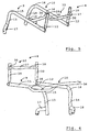
- The invention will be explained in further detail with reference to the accompanying drawings, in which:
- Fig. 1
- is a perspective view of a wheelchair, with certain parts omitted for clarity;
- Fig. 2
- is a side view of the wheelchair's frame in folded condition with rear wheels removed;
- Fig. 3
- is a first perspective view of parts of the wheelchair frame;
- Fig. 4
- is a second perspective view of parts of the wheelchair frame;
- Fig. 5
- is a third perspective view of parts of the wheelchair frame; and
- Fig. 6
- is a fourth perspective view of parts of the wheelchair frame.
- Referring to
Fig. 1 , awheelchair 1 shown here by way of example is supported by left and right rearmain wheels caster wheel assemblies caster wheels wheelchair 1 comprises a base frame andbackrest frame 8. - The base frame comprises left and right
side frame members wheelchair 1. The left and rightside frame members wheelchair 1 has an open frame. Theside frame members first leg second leg first leg second leg curved section first legs second legs first legs first legs - The
first legs wheelchair 1. In particularly, a seat sling (not shown) can be slung between thefirst legs side frame members - The
curved sections side frame members second legs first legs side frame members second legs side frame members - The
second legs caster wheel assemblies caster wheel assemblies second legs second legs side frame members caster wheels wheelchair 1, to provide stability. They are also attached tosecond legs side frame members wheelchair 1, i.e. closer to therear wheels wheelchair 1 relatively good, by shortening the wheelbase. Because thewheelchair 1 has an open frame, it is supported by thecaster wheels second legs caster wheel assemblies first legs side frame members caster wheel assemblies side frame members - It is desirable to place the
rear wheels side frame members wheelchair 1 should be narrow for better manoeuvrability and access to buildings, transport means and the like. This is only possible if the set camber of therear wheels wheelchair 1 is occupied. There must be no "sagging" of the frame, in particular rotation or torsion of theside frame members wheels first legs first legs side frame members first legs first cross-brace 19, and indirectly by anaxle tube 20. Additionally, a foot rest assembly with left and right footrest frame members second legs rest frame members Fig. 1 ) is situated below afoot plate 24. - For adjustment of the height of the
foot plate 24, it is contemplated that the left and right footrest frame members second legs rest frame members rest frame members second legs side frame members - The
first legs side frame members axle tube 20 by arespective axle plate axle tube clamp 27,28 (Fig. 2 ) is connected in one of a number of pre-determined positions on theaxle plate axle tube clamp axle plate axle tube 20 between the different pre-determined positions at varying distances to thefirst legs side frame members 9. The positions are at varying distances to the seat. In this manner, the rear seat height can be adjusted, because theaxle tube 20 accommodates camber tubes (not shown in detail) for holding axles of therear wheels - At least one of the camber tube and the axle is removable from the
axle tube 20, so that therear wheels wheelchair 1 needs to be transported, as is shown inFig. 2 . Thus, the (open) ends of theaxle tube 20 provide housings for removably accommodating rear wheel axles. - The
backrest frame 8 is pivotably connected to the base frame by a connection mechanism that enables left and rightbackrest frame members first legs side frame members right angle plates backrest frame members Fig. 2 , thebackrest frame members first legs side frame members first cross brace 19 between theside frame members second cross-brace 33 provided between thebackrest frame members - The
first cross-brace 19 is comprised of a tubular structure having, seen in longitudinal direction, acentral section 34 and first andsecond end sections end sections side frame members first legs side frame members side frame members central section 34 lies in a plane parallel to the plane defined by thefirst legs central section 34 and a seat supported by the left and rightfirst legs end sections central section 34 can be relatively long, and need not be held exactly under the middle of the seat. In an alternative embodiment, theend sections first legs central section 34 and theend sections - In a similar manner to the
first cross-brace 19, thesecond cross-brace 33 is comprised of a tubular structure having, seen in longitudinal direction, acentral section 37 and first andsecond end sections end sections backrest frame members backrest frame members backrest frame members central section 37 lies in a plane parallel to the plane defined by thebackrest frame members central section 37 and a backrest (not shown) supported by the left and rightbackrest frame members end sections central section 37 can again be relatively long. - Referring to
Fig. 2 , it can be seen that thecentral sections second end sections central section - The oval cross-sections of the
central sections major axes first legs backrest frame members Fig. 2 in particular, it makes sense if one realises that thecentral sections - Referring to
Fig. 1 , thecentral sections coverings cross-brace central section central section -
Fig. 2 further shows that the maximum diameter a1,a2 of eachcentral section - To produce the cross-braces 19, 33, one method starts with a piece of tubing, generally straight. The ends of the piece of tubing that will form the end sections 35-39 are reduced in diameter. Next, the
central sections first cross-brace 19 are bonded, chemically or thermally, e.g. welded, to thefirst legs side frame members second cross-brace 33 are bonded to the left and rightbackrest frame members - Like the other members of the wheelchair frame, the cross-braces 19, 33 can be made of a composite material or a metal or metal alloy. Suitable materials include aluminium-scandium alloys, aluminium alloys from the 7000 series, particularly aluminium 7003, or aluminium from the 6000 series. Aluminium 7000 has a relatively high tensile strength.
- The cross-braces 19, 33 contribute to a strong frame that can be handled relatively easily and comfortably.
- The features mentioned in the description, claims and drawings can be essential to the invention in its various implementations both individually and in any combination.
- It is, for example, possible to provide more than one cross-brace 19 between the
first legs side frame members backrest frame members second legs first legs first legs second legs second legs
Claims (12)
- Wheelchair frame, including• left and right first frame members (9,10), each including at least a first leg (11,12) for supporting a seat, arranged on opposite sides of a central axis aligned with a direction of displacement (d) of the wheelchair, in use, wherein the left and right first frame members (9, 10) including a first leg (11, 12) each include a second leg (13, 14) oriented at an angle to the first leg (11, 12) and transitioning into the first leg (11, 12) via a curved section (15, 16) of the respective first frame member (9, 10), and• left and right second frame members (29, 30) pivotably connected to the left and right first frame members (9, 10) and arrestable in a position in which they are oriented in a direction predominantly parallel to the first legs (11, 12) of the left and right first frame members (9, 10),• at least one first cross-brace (19)- being connected to the first legs (11,12) of the left and right first frame members (9,10) at its ends, characterised in that said at least one first cross-brace further comprises- a non-circular cross-section along at least one section (34) between the ends, and- sections (35,36) having a diameter smaller than at least a maximum diameter of the at least one section (34) with the non-circular cross-section.
- Wheelchair frame according to claim 1, characterised by
at least one second cross-brace (33) connected to the left and right second frame members (29, 30) at its ends and having a non-circular cross-section along at least one section (37) between its end,
preferably with the second cross-brace (33) including sections (38,39)- angled away from a plane defined by the left and right second frame members (29,30) to which the second cross-brace (33) is connected and/or- having a diameter smaller than at least a maximum diameter of the at least one section (37) with the non-circular cross-section. - Wheelchair frame according to claim 1 or 2, wherein
the second frame members (29,30) are arranged to support at least one backrest. - Wheelchair frame according to any one of the preceding claims, wherein
the non-circular cross-section (34, 37) is round, in particular oval in shape. - Wheelchair frame according to claim 1 or any one of the preceding claims, wherein the non-circular cross section (34) of the first cross-brace (19) has a maximum diameter in a direction (40) generally parallel to a plane defined by the first legs (11,12) of the left and right first frame members (9,10).
- Wheelchair frame according to any one of the claims 2 to 5, wherein
the non-circular cross section (37) of the second cross-brace (33) has a maximum diameter in a direction (41) generally parallel to a plane defined by the left and right second frame members (29,30). - Wheelchair frame according to any one of the preceding claims, wherein
at least part of at least the section (34,37) of the cross-brace (19,33) having a non-circular cross-section is covered with a material different from the material of the cross-brace (19,33). - Wheelchair frame according to any one of the preceding claims, wherein
the sections (35,36) of the first cross-brace (19) are angled away from a plane defined by the first left and right frame members (9,10) to which the first cross-brace (19) is connected. - Wheelchair frame according to any of the preceding claims,
including front wheel supports (17,18), each with an end attached to a respective second leg (13,14) and oriented at an angle to the second leg (13,14) so as to be oriented at least partly in a direction opposite to the direction (d) of displacement. - Wheelchair comprising a wheelchair frame according to any one of the preceding claims.
- Wheelchair according to claim 10, including a footrest assembly including left and right members (21,22), removably attached to, in particular insertable in, the second legs (13,14).
- Wheelchair according to claim 10 or 11, further including
left and right supports (25,26), each attached to a respective one of the first legs (11,12) and extending transversely to that first leg (11,12), and
housings (20), attached to the left and right supports (25,26), for removably accommodating rear wheel axles.
Applications Claiming Priority (2)
| Application Number | Priority Date | Filing Date | Title |
|---|---|---|---|
| US880607P | 2007-12-21 | 2007-12-21 | |
| PCT/EP2008/011016 WO2009080347A2 (en) | 2007-12-21 | 2008-12-22 | Wheelchair frame and wheelchair with cross-brace |
Publications (2)
| Publication Number | Publication Date |
|---|---|
| EP2222265A2 EP2222265A2 (en) | 2010-09-01 |
| EP2222265B1 true EP2222265B1 (en) | 2016-11-09 |
Family
ID=40481985
Family Applications (2)
| Application Number | Title | Priority Date | Filing Date |
|---|---|---|---|
| EP08865537A Active EP2219582B1 (en) | 2007-12-21 | 2008-12-22 | Caster strut, wheelchair frame and wheelchair |
| EP08863436.5A Active EP2222265B1 (en) | 2007-12-21 | 2008-12-22 | Wheelchair frame and wheelchair with cross-brace |
Family Applications Before (1)
| Application Number | Title | Priority Date | Filing Date |
|---|---|---|---|
| EP08865537A Active EP2219582B1 (en) | 2007-12-21 | 2008-12-22 | Caster strut, wheelchair frame and wheelchair |
Country Status (5)
| Country | Link |
|---|---|
| US (2) | US8490994B2 (en) |
| EP (2) | EP2219582B1 (en) |
| AT (1) | ATE553737T1 (en) |
| DE (1) | DE202008017981U1 (en) |
| WO (3) | WO2009080346A1 (en) |
Cited By (1)
| Publication number | Priority date | Publication date | Assignee | Title |
|---|---|---|---|---|
| US12409085B2 (en) | 2022-07-07 | 2025-09-09 | Permobil Ab | Powered midwheel drive wheelchair with standing capability |
Families Citing this family (9)
| Publication number | Priority date | Publication date | Assignee | Title |
|---|---|---|---|---|
| EP2606868A1 (en) * | 2011-12-21 | 2013-06-26 | Invacare International Sàrl | Easily dissociable wheelchair |
| CN102864352B (en) * | 2012-09-04 | 2014-02-26 | 古交市银河镁业有限公司 | Magnesium alloy and device and method for machining magnesium alloy handrail ring of wheelchair |
| CA3015844C (en) * | 2016-03-01 | 2022-04-12 | Motion Composites Inc | Wheelchair frame |
| CN106038109A (en) * | 2016-08-15 | 2016-10-26 | 江阴市新盛医疗器材设备有限公司 | Wheelchair supporting frame |
| CN210494426U (en) | 2019-05-08 | 2020-05-12 | 明门(中国)幼童用品有限公司 | Backrest adjusting mechanism and nursing vehicle with same |
| US12508179B2 (en) | 2022-01-26 | 2025-12-30 | Permobil, Inc. | Wheelchair |
| USD1054330S1 (en) | 2022-01-26 | 2024-12-17 | Permobil, Inc. | Wheelchair |
| USD1054331S1 (en) | 2022-01-26 | 2024-12-17 | Permobil, Inc. | Wheelchair |
| CA3168572C (en) | 2022-07-13 | 2025-08-05 | Invacare Corporation | Wheelchair and suspension systems |
Citations (2)
| Publication number | Priority date | Publication date | Assignee | Title |
|---|---|---|---|---|
| EP1116480A1 (en) * | 1999-10-11 | 2001-07-18 | Invacare Rea AB | A wheel chair |
| WO2007112508A1 (en) * | 2006-04-04 | 2007-10-11 | Lu Papi & Associates Pty Ltd | Wheelchair |
Family Cites Families (58)
| Publication number | Priority date | Publication date | Assignee | Title |
|---|---|---|---|---|
| BE529233A (en) | ||||
| GB758830A (en) * | 1953-09-12 | 1956-10-10 | Edwin Stanley Freeman | A new or improved process of bending tubes |
| US4592570A (en) * | 1983-10-27 | 1986-06-03 | Everest & Jennings | Ultra light wheelchair |
| CH671332A5 (en) | 1986-07-31 | 1989-08-31 | Rainer Kueschall C O Paratec A | |
| US4966379A (en) | 1987-10-19 | 1990-10-30 | Mulholland Designs, Inc. | Reclinable wheelchair |
| US5020817A (en) * | 1987-10-30 | 1991-06-04 | Rober K. Leib | Wheelchair |
| US4858260A (en) * | 1988-03-11 | 1989-08-22 | Hausted, Inc. | Patient transport apparatus including Trendelenburg mechanism and guard rail |
| DE8906096U1 (en) | 1989-05-17 | 1989-07-13 | Günter Meier GmbH, 4952 Porta Westfalica | Wheelchair for disabled and sick people |
| US5131672A (en) | 1990-04-27 | 1992-07-21 | Medical Composite Technology | Camber adjustment fitting for a wheelchair |
| WO1991017077A1 (en) | 1990-04-27 | 1991-11-14 | Medical Composite Technology | Modular wheelchair |
| US5176393A (en) | 1990-04-27 | 1993-01-05 | Medical Composite Technology | Modular wheelchair |
| US5076602A (en) * | 1990-04-27 | 1991-12-31 | Medical Composite Technology | Seating system for a wheel chair |
| US5143391A (en) * | 1990-04-27 | 1992-09-01 | Medical Composite Technology | Modular wheelchair |
| US5076390A (en) * | 1990-07-03 | 1991-12-31 | Haskins John T | Multiple mode wheelchair construction |
| US5152543A (en) * | 1990-11-15 | 1992-10-06 | Everest & Jennings, Inc | Composite frame wheelchair |
| US5421598A (en) | 1991-04-26 | 1995-06-06 | Everest & Jennings International, Ltd. | Modular wheelchair |
| US5267745A (en) * | 1991-11-08 | 1993-12-07 | Medical Composite Technology, Inc. | Wheelchair and wheelchair frame |
| JP3449491B2 (en) * | 1992-10-06 | 2003-09-22 | 臼井国際産業株式会社 | How to bend a metal tube with a small radius of curvature |
| NL1001164C2 (en) | 1995-09-08 | 1997-03-11 | Revab Bv | Multifunctional wheelchair. |
| JP3587621B2 (en) * | 1996-04-25 | 2004-11-10 | 株式会社日立製作所 | Standing walking motion assist device |
| US6464243B2 (en) * | 1996-10-15 | 2002-10-15 | James Roche | Wheel chair |
| JPH10175026A (en) * | 1996-12-17 | 1998-06-30 | Nippon Steel Corp | Pipe hydroforming method |
| US5957474A (en) * | 1997-02-24 | 1999-09-28 | Pdg Inc. | Wheelchair for large individuals |
| DE29705494U1 (en) | 1997-03-26 | 1997-05-22 | MEYRA Wilhelm Meyer GmbH & Co KG, 32689 Kalletal | Sports wheelchair |
| CH692179A5 (en) * | 1997-06-25 | 2002-03-15 | Kueschall Design Ag | Wheelchair and seat module for the wheelchair, |
| CH689177A5 (en) | 1997-12-23 | 1998-11-30 | Kueschall Design Ag | Wheelchair with a closed three-dimensional frame. |
| DE19821021C2 (en) | 1998-05-11 | 2000-08-31 | Meyra Wilhelm Meyer Gmbh & Co | Framework for a wheelchair |
| US20030006578A1 (en) * | 1998-10-01 | 2003-01-09 | Freedom Designs Incorporated | Size-adjustable laterally-folding tilting-frame wheelchair |
| DE29901471U1 (en) | 1999-01-29 | 1999-07-22 | Sopur Medizintechnik GmbH, 69254 Malsch | Manually operated wheelchair |
| US6309170B1 (en) * | 1999-08-17 | 2001-10-30 | Roger Vartanian | Vehicle wheelchair lift with mutually perpendicular pivot axes and parallelogram transport |
| FR2799641B1 (en) | 1999-10-19 | 2002-01-25 | Serge Klipfel | MANUAL, ERGONOMIC, THREE-WHEEL WHEELCHAIR WITH VARIABLE SUSPENSION AND SEAT HEIGHT |
| US6419253B1 (en) * | 2000-05-01 | 2002-07-16 | Invacare Corporation | Wheelchair having a double turnbuckle height adjustment |
| JP2001314452A (en) * | 2000-05-09 | 2001-11-13 | Bridgestone Cycle Co | Wheelchair brake and wheelchair using the same |
| IT1315695B1 (en) | 2000-05-16 | 2003-03-18 | Vassilli Srl | WHEELCHAIR FOR DISABLED PEOPLE WITH THE ADJUSTMENT OF THE CARRIER OF THE CARRIER WHEELS. |
| US6394476B1 (en) | 2000-08-10 | 2002-05-28 | Invacare Corporation | Wheelchair seat having adjustable telescoping assembly |
| SE523441C2 (en) | 2001-12-11 | 2004-04-20 | Etac Ab | Wheelchair with adjustable upper and lower frame |
| US7353566B2 (en) | 2002-06-05 | 2008-04-08 | Sunrise Medical Hhg Inc. | Adjustable wheel assembly |
| US7231689B2 (en) * | 2002-06-05 | 2007-06-19 | Sunrise Medical Hhg Inc. | Adjustable wheel assembly |
| US20040104321A1 (en) | 2002-08-06 | 2004-06-03 | Marsolais Thomas R. | Adjustable connector for I.V. poles and medical devices |
| DE20316246U1 (en) | 2003-03-04 | 2003-12-18 | Invacare Ag | Wheelchair frame has rear axle suspension system with clamping devices which can be released to allow axle to be pivoted into different position |
| US8474848B2 (en) * | 2003-03-31 | 2013-07-02 | Sunrise Medical (Us) Llc | Personal mobility vehicle with tiltable seat |
| US7007965B2 (en) * | 2003-03-31 | 2006-03-07 | Sunrise Medical Hhg Inc. | Center-of-gravity tilt-in-space wheelchair |
| WO2005067857A1 (en) | 2004-01-14 | 2005-07-28 | Invacare Corporation | Adjustable wheelchair |
| US7360781B2 (en) * | 2004-01-23 | 2008-04-22 | Sunrise Medical Hhg Inc. | Foldable wheelchair and axle plate therefor |
| DE202004007928U1 (en) | 2004-05-17 | 2004-07-22 | Meyra Wilhelm Meyer Gmbh & Co. Kg | wheelchair |
| US7520518B2 (en) * | 2004-10-25 | 2009-04-21 | Invacare Corporation | Wheelchair |
| EP1814502A1 (en) * | 2004-10-29 | 2007-08-08 | R82 A/S | Comfort wheelchair |
| GB0509917D0 (en) | 2005-05-14 | 2005-06-22 | Specialised Orthotic Services | Wheelchairs |
| US7455362B2 (en) * | 2005-07-14 | 2008-11-25 | Kids Up, Inc. | Adjustable motion wheel chair |
| CH698713B1 (en) | 2006-04-26 | 2009-10-15 | Heinz Duerst | Wheelchair. |
| EP1900349A1 (en) | 2006-09-18 | 2008-03-19 | Invacare International Sàrl | Support device for wheelchair |
| CA2581578A1 (en) * | 2006-09-22 | 2008-03-22 | Mike Ehman | Step climbing wheelchair |
| US7950684B2 (en) * | 2006-10-25 | 2011-05-31 | Jaimie Borisoff | Wheelchair side guards |
| JP4616865B2 (en) * | 2007-07-20 | 2011-01-19 | 英一 元田 | Driving force automatic release type unidirectional rotation drive device |
| US7896385B2 (en) * | 2007-09-21 | 2011-03-01 | Michael Every | Foldable wheelchair |
| US8002300B2 (en) * | 2007-09-28 | 2011-08-23 | Tisport, Llc | Rear wheel mounting assembly for a wheelchair |
| US7810613B2 (en) * | 2007-11-29 | 2010-10-12 | Ching-Sung Lin | Cart braking device |
| US7891696B2 (en) * | 2008-06-17 | 2011-02-22 | Hanson Wayne H | Multifunctional foldable mobility base |
-
2008
- 2008-12-22 AT AT08865537T patent/ATE553737T1/en active
- 2008-12-22 DE DE202008017981U patent/DE202008017981U1/en not_active Expired - Lifetime
- 2008-12-22 US US12/809,818 patent/US8490994B2/en active Active
- 2008-12-22 WO PCT/EP2008/011015 patent/WO2009080346A1/en not_active Ceased
- 2008-12-22 EP EP08865537A patent/EP2219582B1/en active Active
- 2008-12-22 WO PCT/EP2008/011016 patent/WO2009080347A2/en not_active Ceased
- 2008-12-22 US US12/809,807 patent/US20110018222A1/en not_active Abandoned
- 2008-12-22 EP EP08863436.5A patent/EP2222265B1/en active Active
- 2008-12-22 WO PCT/EP2008/011017 patent/WO2009080348A1/en not_active Ceased
Patent Citations (2)
| Publication number | Priority date | Publication date | Assignee | Title |
|---|---|---|---|---|
| EP1116480A1 (en) * | 1999-10-11 | 2001-07-18 | Invacare Rea AB | A wheel chair |
| WO2007112508A1 (en) * | 2006-04-04 | 2007-10-11 | Lu Papi & Associates Pty Ltd | Wheelchair |
Cited By (1)
| Publication number | Priority date | Publication date | Assignee | Title |
|---|---|---|---|---|
| US12409085B2 (en) | 2022-07-07 | 2025-09-09 | Permobil Ab | Powered midwheel drive wheelchair with standing capability |
Also Published As
| Publication number | Publication date |
|---|---|
| US20110018222A1 (en) | 2011-01-27 |
| EP2219582A1 (en) | 2010-08-25 |
| WO2009080347A2 (en) | 2009-07-02 |
| DE202008017981U1 (en) | 2011-02-17 |
| WO2009080346A4 (en) | 2009-09-11 |
| WO2009080346A1 (en) | 2009-07-02 |
| EP2219582B1 (en) | 2012-04-18 |
| US20110025014A1 (en) | 2011-02-03 |
| WO2009080347A4 (en) | 2009-11-12 |
| ATE553737T1 (en) | 2012-05-15 |
| US8490994B2 (en) | 2013-07-23 |
| EP2222265A2 (en) | 2010-09-01 |
| WO2009080347A3 (en) | 2009-09-03 |
| WO2009080348A4 (en) | 2009-10-22 |
| WO2009080348A1 (en) | 2009-07-02 |
Similar Documents
| Publication | Publication Date | Title |
|---|---|---|
| WO2009080347A2 (en) | Wheelchair frame and wheelchair with cross-brace | |
| EP2213270B1 (en) | Assembly including a frame and wheelchair including such an assembly | |
| EP2007337B1 (en) | Wheelchair | |
| CA2198643C (en) | Wheelchair for large individuals | |
| CN203619856U (en) | foldable rollator | |
| US7302718B2 (en) | Multiple level roll-in cot | |
| EP2213269B1 (en) | Personal conveyance, e.g. wheelchair, and frame assembly therefor | |
| AU2010319339B2 (en) | Wheelchair | |
| US5480179A (en) | Wheelchair chassis | |
| EP1981462B1 (en) | Ambulance cot with improved drop frame | |
| AU2001281097B2 (en) | A wheelchair seat having adjustable telescoping assembly | |
| US7364184B2 (en) | Mobility assist devices | |
| AU2001281097A1 (en) | A wheelchair seat having adjustable telescoping assembly | |
| EP2213268B1 (en) | Frame member and frame for a personal conveyance, e.g. a wheelchair | |
| EP1295582B1 (en) | Wheelchair with a self-supporting sitting support and method for manufacturing same | |
| US20070102901A1 (en) | Body frame for wheelchair | |
| JP2025517029A (en) | Folding stretcher with wheels | |
| RU89382U1 (en) | FOLDING CHAIR | |
| JP3231125U (en) | Chair | |
| EP2263630A1 (en) | Wheelchairs | |
| AU661936B2 (en) | Improvements in, or relating to wheelchairs | |
| GB2304314A (en) | Collapsible wheelchair | |
| WO1995006581A1 (en) | Folding wheelchair | |
| WO2004112674A2 (en) | Improvements in or relating to disability vehicles and fastening devices | |
| AU2013221981A1 (en) | Wheelchair |
Legal Events
| Date | Code | Title | Description |
|---|---|---|---|
| PUAI | Public reference made under article 153(3) epc to a published international application that has entered the european phase |
Free format text: ORIGINAL CODE: 0009012 |
|
| 17P | Request for examination filed |
Effective date: 20100617 |
|
| AK | Designated contracting states |
Kind code of ref document: A2 Designated state(s): AT BE BG CH CY CZ DE DK EE ES FI FR GB GR HR HU IE IS IT LI LT LU LV MC MT NL NO PL PT RO SE SI SK TR |
|
| AX | Request for extension of the european patent |
Extension state: AL BA MK RS |
|
| DAX | Request for extension of the european patent (deleted) | ||
| 17Q | First examination report despatched |
Effective date: 20110302 |
|
| REG | Reference to a national code |
Ref country code: DE Ref legal event code: R079 Ref document number: 602008047329 Country of ref document: DE Free format text: PREVIOUS MAIN CLASS: A61G0005000000 Ipc: A61G0005020000 |
|
| RIC1 | Information provided on ipc code assigned before grant |
Ipc: A61G 5/10 20060101ALI20160310BHEP Ipc: A61G 5/02 20060101AFI20160310BHEP |
|
| GRAP | Despatch of communication of intention to grant a patent |
Free format text: ORIGINAL CODE: EPIDOSNIGR1 |
|
| INTG | Intention to grant announced |
Effective date: 20160601 |
|
| GRAS | Grant fee paid |
Free format text: ORIGINAL CODE: EPIDOSNIGR3 |
|
| GRAA | (expected) grant |
Free format text: ORIGINAL CODE: 0009210 |
|
| AK | Designated contracting states |
Kind code of ref document: B1 Designated state(s): AT BE BG CH CY CZ DE DK EE ES FI FR GB GR HR HU IE IS IT LI LT LU LV MC MT NL NO PL PT RO SE SI SK TR |
|
| REG | Reference to a national code |
Ref country code: GB Ref legal event code: FG4D |
|
| REG | Reference to a national code |
Ref country code: AT Ref legal event code: REF Ref document number: 843202 Country of ref document: AT Kind code of ref document: T Effective date: 20161115 Ref country code: CH Ref legal event code: EP |
|
| REG | Reference to a national code |
Ref country code: IE Ref legal event code: FG4D |
|
| REG | Reference to a national code |
Ref country code: DE Ref legal event code: R096 Ref document number: 602008047329 Country of ref document: DE |
|
| REG | Reference to a national code |
Ref country code: FR Ref legal event code: PLFP Year of fee payment: 9 |
|
| REG | Reference to a national code |
Ref country code: NL Ref legal event code: FP |
|
| PG25 | Lapsed in a contracting state [announced via postgrant information from national office to epo] |
Ref country code: LV Free format text: LAPSE BECAUSE OF FAILURE TO SUBMIT A TRANSLATION OF THE DESCRIPTION OR TO PAY THE FEE WITHIN THE PRESCRIBED TIME-LIMIT Effective date: 20161109 |
|
| REG | Reference to a national code |
Ref country code: LT Ref legal event code: MG4D |
|
| REG | Reference to a national code |
Ref country code: DE Ref legal event code: R081 Ref document number: 602008047329 Country of ref document: DE Owner name: SUNRISE MEDICAL GMBH, DE Free format text: FORMER OWNER: SUNRISE MEDICAL GMBH & CO. KG, 69254 MALSCH, DE Ref country code: DE Ref legal event code: R082 Ref document number: 602008047329 Country of ref document: DE Representative=s name: JONES DAY RECHTSANWAELTE PATENTANWAELTE, DE |
|
| REG | Reference to a national code |
Ref country code: AT Ref legal event code: MK05 Ref document number: 843202 Country of ref document: AT Kind code of ref document: T Effective date: 20161109 |
|
| PG25 | Lapsed in a contracting state [announced via postgrant information from national office to epo] |
Ref country code: LT Free format text: LAPSE BECAUSE OF FAILURE TO SUBMIT A TRANSLATION OF THE DESCRIPTION OR TO PAY THE FEE WITHIN THE PRESCRIBED TIME-LIMIT Effective date: 20161109 Ref country code: GR Free format text: LAPSE BECAUSE OF FAILURE TO SUBMIT A TRANSLATION OF THE DESCRIPTION OR TO PAY THE FEE WITHIN THE PRESCRIBED TIME-LIMIT Effective date: 20170210 Ref country code: NO Free format text: LAPSE BECAUSE OF FAILURE TO SUBMIT A TRANSLATION OF THE DESCRIPTION OR TO PAY THE FEE WITHIN THE PRESCRIBED TIME-LIMIT Effective date: 20170209 Ref country code: SE Free format text: LAPSE BECAUSE OF FAILURE TO SUBMIT A TRANSLATION OF THE DESCRIPTION OR TO PAY THE FEE WITHIN THE PRESCRIBED TIME-LIMIT Effective date: 20161109 |
|
| PG25 | Lapsed in a contracting state [announced via postgrant information from national office to epo] |
Ref country code: BE Free format text: LAPSE BECAUSE OF NON-PAYMENT OF DUE FEES Effective date: 20161231 Ref country code: ES Free format text: LAPSE BECAUSE OF FAILURE TO SUBMIT A TRANSLATION OF THE DESCRIPTION OR TO PAY THE FEE WITHIN THE PRESCRIBED TIME-LIMIT Effective date: 20161109 Ref country code: AT Free format text: LAPSE BECAUSE OF FAILURE TO SUBMIT A TRANSLATION OF THE DESCRIPTION OR TO PAY THE FEE WITHIN THE PRESCRIBED TIME-LIMIT Effective date: 20161109 Ref country code: IS Free format text: LAPSE BECAUSE OF FAILURE TO SUBMIT A TRANSLATION OF THE DESCRIPTION OR TO PAY THE FEE WITHIN THE PRESCRIBED TIME-LIMIT Effective date: 20170309 Ref country code: PT Free format text: LAPSE BECAUSE OF FAILURE TO SUBMIT A TRANSLATION OF THE DESCRIPTION OR TO PAY THE FEE WITHIN THE PRESCRIBED TIME-LIMIT Effective date: 20170309 Ref country code: PL Free format text: LAPSE BECAUSE OF FAILURE TO SUBMIT A TRANSLATION OF THE DESCRIPTION OR TO PAY THE FEE WITHIN THE PRESCRIBED TIME-LIMIT Effective date: 20161109 Ref country code: HR Free format text: LAPSE BECAUSE OF FAILURE TO SUBMIT A TRANSLATION OF THE DESCRIPTION OR TO PAY THE FEE WITHIN THE PRESCRIBED TIME-LIMIT Effective date: 20161109 Ref country code: FI Free format text: LAPSE BECAUSE OF FAILURE TO SUBMIT A TRANSLATION OF THE DESCRIPTION OR TO PAY THE FEE WITHIN THE PRESCRIBED TIME-LIMIT Effective date: 20161109 |
|
| PG25 | Lapsed in a contracting state [announced via postgrant information from national office to epo] |
Ref country code: CZ Free format text: LAPSE BECAUSE OF FAILURE TO SUBMIT A TRANSLATION OF THE DESCRIPTION OR TO PAY THE FEE WITHIN THE PRESCRIBED TIME-LIMIT Effective date: 20161109 Ref country code: RO Free format text: LAPSE BECAUSE OF FAILURE TO SUBMIT A TRANSLATION OF THE DESCRIPTION OR TO PAY THE FEE WITHIN THE PRESCRIBED TIME-LIMIT Effective date: 20161109 Ref country code: EE Free format text: LAPSE BECAUSE OF FAILURE TO SUBMIT A TRANSLATION OF THE DESCRIPTION OR TO PAY THE FEE WITHIN THE PRESCRIBED TIME-LIMIT Effective date: 20161109 Ref country code: DK Free format text: LAPSE BECAUSE OF FAILURE TO SUBMIT A TRANSLATION OF THE DESCRIPTION OR TO PAY THE FEE WITHIN THE PRESCRIBED TIME-LIMIT Effective date: 20161109 Ref country code: SK Free format text: LAPSE BECAUSE OF FAILURE TO SUBMIT A TRANSLATION OF THE DESCRIPTION OR TO PAY THE FEE WITHIN THE PRESCRIBED TIME-LIMIT Effective date: 20161109 |
|
| REG | Reference to a national code |
Ref country code: CH Ref legal event code: PL |
|
| REG | Reference to a national code |
Ref country code: DE Ref legal event code: R097 Ref document number: 602008047329 Country of ref document: DE |
|
| PG25 | Lapsed in a contracting state [announced via postgrant information from national office to epo] |
Ref country code: BG Free format text: LAPSE BECAUSE OF FAILURE TO SUBMIT A TRANSLATION OF THE DESCRIPTION OR TO PAY THE FEE WITHIN THE PRESCRIBED TIME-LIMIT Effective date: 20170209 Ref country code: BE Free format text: LAPSE BECAUSE OF FAILURE TO SUBMIT A TRANSLATION OF THE DESCRIPTION OR TO PAY THE FEE WITHIN THE PRESCRIBED TIME-LIMIT Effective date: 20161109 |
|
| PLBE | No opposition filed within time limit |
Free format text: ORIGINAL CODE: 0009261 |
|
| STAA | Information on the status of an ep patent application or granted ep patent |
Free format text: STATUS: NO OPPOSITION FILED WITHIN TIME LIMIT |
|
| PG25 | Lapsed in a contracting state [announced via postgrant information from national office to epo] |
Ref country code: MC Free format text: LAPSE BECAUSE OF FAILURE TO SUBMIT A TRANSLATION OF THE DESCRIPTION OR TO PAY THE FEE WITHIN THE PRESCRIBED TIME-LIMIT Effective date: 20161109 |
|
| REG | Reference to a national code |
Ref country code: IE Ref legal event code: MM4A |
|
| 26N | No opposition filed |
Effective date: 20170810 |
|
| PG25 | Lapsed in a contracting state [announced via postgrant information from national office to epo] |
Ref country code: LU Free format text: LAPSE BECAUSE OF NON-PAYMENT OF DUE FEES Effective date: 20161222 Ref country code: CH Free format text: LAPSE BECAUSE OF NON-PAYMENT OF DUE FEES Effective date: 20161231 Ref country code: LI Free format text: LAPSE BECAUSE OF NON-PAYMENT OF DUE FEES Effective date: 20161231 |
|
| PG25 | Lapsed in a contracting state [announced via postgrant information from national office to epo] |
Ref country code: SI Free format text: LAPSE BECAUSE OF FAILURE TO SUBMIT A TRANSLATION OF THE DESCRIPTION OR TO PAY THE FEE WITHIN THE PRESCRIBED TIME-LIMIT Effective date: 20161109 Ref country code: IE Free format text: LAPSE BECAUSE OF NON-PAYMENT OF DUE FEES Effective date: 20161222 |
|
| REG | Reference to a national code |
Ref country code: FR Ref legal event code: PLFP Year of fee payment: 10 |
|
| PG25 | Lapsed in a contracting state [announced via postgrant information from national office to epo] |
Ref country code: HU Free format text: LAPSE BECAUSE OF FAILURE TO SUBMIT A TRANSLATION OF THE DESCRIPTION OR TO PAY THE FEE WITHIN THE PRESCRIBED TIME-LIMIT; INVALID AB INITIO Effective date: 20081222 Ref country code: CY Free format text: LAPSE BECAUSE OF FAILURE TO SUBMIT A TRANSLATION OF THE DESCRIPTION OR TO PAY THE FEE WITHIN THE PRESCRIBED TIME-LIMIT Effective date: 20161109 |
|
| PG25 | Lapsed in a contracting state [announced via postgrant information from national office to epo] |
Ref country code: TR Free format text: LAPSE BECAUSE OF FAILURE TO SUBMIT A TRANSLATION OF THE DESCRIPTION OR TO PAY THE FEE WITHIN THE PRESCRIBED TIME-LIMIT Effective date: 20161109 |
|
| PG25 | Lapsed in a contracting state [announced via postgrant information from national office to epo] |
Ref country code: MT Free format text: LAPSE BECAUSE OF NON-PAYMENT OF DUE FEES Effective date: 20161222 |
|
| P01 | Opt-out of the competence of the unified patent court (upc) registered |
Effective date: 20230619 |
|
| PGFP | Annual fee paid to national office [announced via postgrant information from national office to epo] |
Ref country code: GB Payment date: 20251218 Year of fee payment: 18 |
|
| PGFP | Annual fee paid to national office [announced via postgrant information from national office to epo] |
Ref country code: FR Payment date: 20251217 Year of fee payment: 18 Ref country code: NL Payment date: 20251217 Year of fee payment: 18 |
|
| PGFP | Annual fee paid to national office [announced via postgrant information from national office to epo] |
Ref country code: DE Payment date: 20251222 Year of fee payment: 18 |
|
| PGFP | Annual fee paid to national office [announced via postgrant information from national office to epo] |
Ref country code: IT Payment date: 20251231 Year of fee payment: 18 |