EP2221958A1 - Wind power generation system and its operation control method - Google Patents
Wind power generation system and its operation control method Download PDFInfo
- Publication number
- EP2221958A1 EP2221958A1 EP07850625A EP07850625A EP2221958A1 EP 2221958 A1 EP2221958 A1 EP 2221958A1 EP 07850625 A EP07850625 A EP 07850625A EP 07850625 A EP07850625 A EP 07850625A EP 2221958 A1 EP2221958 A1 EP 2221958A1
- Authority
- EP
- European Patent Office
- Prior art keywords
- power
- wind turbines
- factor
- individual
- interconnection node
- Prior art date
- Legal status (The legal status is an assumption and is not a legal conclusion. Google has not performed a legal analysis and makes no representation as to the accuracy of the status listed.)
- Withdrawn
Links
- 238000010248 power generation Methods 0.000 title claims description 28
- 238000000034 method Methods 0.000 title claims description 23
- 238000012937 correction Methods 0.000 claims abstract description 35
- 230000005284 excitation Effects 0.000 description 6
- 238000010586 diagram Methods 0.000 description 4
- 239000003990 capacitor Substances 0.000 description 1
- 238000004891 communication Methods 0.000 description 1
- 238000007796 conventional method Methods 0.000 description 1
- 238000013461 design Methods 0.000 description 1
- 238000001514 detection method Methods 0.000 description 1
Images

Classifications
-
- H—ELECTRICITY
- H02—GENERATION; CONVERSION OR DISTRIBUTION OF ELECTRIC POWER
- H02J—CIRCUIT ARRANGEMENTS OR SYSTEMS FOR SUPPLYING OR DISTRIBUTING ELECTRIC POWER; SYSTEMS FOR STORING ELECTRIC ENERGY
- H02J3/00—Circuit arrangements for ac mains or ac distribution networks
- H02J3/38—Arrangements for parallely feeding a single network by two or more generators, converters or transformers
- H02J3/46—Controlling of the sharing of output between the generators, converters, or transformers
- H02J3/48—Controlling the sharing of the in-phase component
-
- F—MECHANICAL ENGINEERING; LIGHTING; HEATING; WEAPONS; BLASTING
- F03—MACHINES OR ENGINES FOR LIQUIDS; WIND, SPRING, OR WEIGHT MOTORS; PRODUCING MECHANICAL POWER OR A REACTIVE PROPULSIVE THRUST, NOT OTHERWISE PROVIDED FOR
- F03D—WIND MOTORS
- F03D7/00—Controlling wind motors
-
- F—MECHANICAL ENGINEERING; LIGHTING; HEATING; WEAPONS; BLASTING
- F03—MACHINES OR ENGINES FOR LIQUIDS; WIND, SPRING, OR WEIGHT MOTORS; PRODUCING MECHANICAL POWER OR A REACTIVE PROPULSIVE THRUST, NOT OTHERWISE PROVIDED FOR
- F03D—WIND MOTORS
- F03D7/00—Controlling wind motors
- F03D7/02—Controlling wind motors the wind motors having rotation axis substantially parallel to the air flow entering the rotor
- F03D7/028—Controlling wind motors the wind motors having rotation axis substantially parallel to the air flow entering the rotor controlling wind motor output power
-
- F—MECHANICAL ENGINEERING; LIGHTING; HEATING; WEAPONS; BLASTING
- F03—MACHINES OR ENGINES FOR LIQUIDS; WIND, SPRING, OR WEIGHT MOTORS; PRODUCING MECHANICAL POWER OR A REACTIVE PROPULSIVE THRUST, NOT OTHERWISE PROVIDED FOR
- F03D—WIND MOTORS
- F03D7/00—Controlling wind motors
- F03D7/02—Controlling wind motors the wind motors having rotation axis substantially parallel to the air flow entering the rotor
- F03D7/04—Automatic control; Regulation
- F03D7/042—Automatic control; Regulation by means of an electrical or electronic controller
- F03D7/048—Automatic control; Regulation by means of an electrical or electronic controller controlling wind farms
-
- H—ELECTRICITY
- H02—GENERATION; CONVERSION OR DISTRIBUTION OF ELECTRIC POWER
- H02J—CIRCUIT ARRANGEMENTS OR SYSTEMS FOR SUPPLYING OR DISTRIBUTING ELECTRIC POWER; SYSTEMS FOR STORING ELECTRIC ENERGY
- H02J3/00—Circuit arrangements for ac mains or ac distribution networks
- H02J3/18—Arrangements for adjusting, eliminating or compensating reactive power in networks
- H02J3/1885—Arrangements for adjusting, eliminating or compensating reactive power in networks using rotating means, e.g. synchronous generators
-
- H—ELECTRICITY
- H02—GENERATION; CONVERSION OR DISTRIBUTION OF ELECTRIC POWER
- H02J—CIRCUIT ARRANGEMENTS OR SYSTEMS FOR SUPPLYING OR DISTRIBUTING ELECTRIC POWER; SYSTEMS FOR STORING ELECTRIC ENERGY
- H02J3/00—Circuit arrangements for ac mains or ac distribution networks
- H02J3/38—Arrangements for parallely feeding a single network by two or more generators, converters or transformers
- H02J3/381—Dispersed generators
-
- H—ELECTRICITY
- H02—GENERATION; CONVERSION OR DISTRIBUTION OF ELECTRIC POWER
- H02J—CIRCUIT ARRANGEMENTS OR SYSTEMS FOR SUPPLYING OR DISTRIBUTING ELECTRIC POWER; SYSTEMS FOR STORING ELECTRIC ENERGY
- H02J3/00—Circuit arrangements for ac mains or ac distribution networks
- H02J3/38—Arrangements for parallely feeding a single network by two or more generators, converters or transformers
- H02J3/46—Controlling of the sharing of output between the generators, converters, or transformers
- H02J3/50—Controlling the sharing of the out-of-phase component
-
- H—ELECTRICITY
- H02—GENERATION; CONVERSION OR DISTRIBUTION OF ELECTRIC POWER
- H02P—CONTROL OR REGULATION OF ELECTRIC MOTORS, ELECTRIC GENERATORS OR DYNAMO-ELECTRIC CONVERTERS; CONTROLLING TRANSFORMERS, REACTORS OR CHOKE COILS
- H02P23/00—Arrangements or methods for the control of AC motors characterised by a control method other than vector control
- H02P23/26—Power factor control [PFC]
-
- F—MECHANICAL ENGINEERING; LIGHTING; HEATING; WEAPONS; BLASTING
- F05—INDEXING SCHEMES RELATING TO ENGINES OR PUMPS IN VARIOUS SUBCLASSES OF CLASSES F01-F04
- F05B—INDEXING SCHEME RELATING TO WIND, SPRING, WEIGHT, INERTIA OR LIKE MOTORS, TO MACHINES OR ENGINES FOR LIQUIDS COVERED BY SUBCLASSES F03B, F03D AND F03G
- F05B2240/00—Components
- F05B2240/40—Use of a multiplicity of similar components
-
- H—ELECTRICITY
- H02—GENERATION; CONVERSION OR DISTRIBUTION OF ELECTRIC POWER
- H02J—CIRCUIT ARRANGEMENTS OR SYSTEMS FOR SUPPLYING OR DISTRIBUTING ELECTRIC POWER; SYSTEMS FOR STORING ELECTRIC ENERGY
- H02J2300/00—Systems for supplying or distributing electric power characterised by decentralized, dispersed, or local generation
- H02J2300/20—The dispersed energy generation being of renewable origin
- H02J2300/28—The renewable source being wind energy
-
- H—ELECTRICITY
- H02—GENERATION; CONVERSION OR DISTRIBUTION OF ELECTRIC POWER
- H02P—CONTROL OR REGULATION OF ELECTRIC MOTORS, ELECTRIC GENERATORS OR DYNAMO-ELECTRIC CONVERTERS; CONTROLLING TRANSFORMERS, REACTORS OR CHOKE COILS
- H02P2201/00—Indexing scheme relating to controlling arrangements characterised by the converter used
- H02P2201/15—Power factor Correction [PFC] circuit generating the DC link voltage for motor driving inverter
-
- Y—GENERAL TAGGING OF NEW TECHNOLOGICAL DEVELOPMENTS; GENERAL TAGGING OF CROSS-SECTIONAL TECHNOLOGIES SPANNING OVER SEVERAL SECTIONS OF THE IPC; TECHNICAL SUBJECTS COVERED BY FORMER USPC CROSS-REFERENCE ART COLLECTIONS [XRACs] AND DIGESTS
- Y02—TECHNOLOGIES OR APPLICATIONS FOR MITIGATION OR ADAPTATION AGAINST CLIMATE CHANGE
- Y02E—REDUCTION OF GREENHOUSE GAS [GHG] EMISSIONS, RELATED TO ENERGY GENERATION, TRANSMISSION OR DISTRIBUTION
- Y02E10/00—Energy generation through renewable energy sources
- Y02E10/70—Wind energy
- Y02E10/72—Wind turbines with rotation axis in wind direction
-
- Y—GENERAL TAGGING OF NEW TECHNOLOGICAL DEVELOPMENTS; GENERAL TAGGING OF CROSS-SECTIONAL TECHNOLOGIES SPANNING OVER SEVERAL SECTIONS OF THE IPC; TECHNICAL SUBJECTS COVERED BY FORMER USPC CROSS-REFERENCE ART COLLECTIONS [XRACs] AND DIGESTS
- Y02—TECHNOLOGIES OR APPLICATIONS FOR MITIGATION OR ADAPTATION AGAINST CLIMATE CHANGE
- Y02E—REDUCTION OF GREENHOUSE GAS [GHG] EMISSIONS, RELATED TO ENERGY GENERATION, TRANSMISSION OR DISTRIBUTION
- Y02E10/00—Energy generation through renewable energy sources
- Y02E10/70—Wind energy
- Y02E10/76—Power conversion electric or electronic aspects
-
- Y—GENERAL TAGGING OF NEW TECHNOLOGICAL DEVELOPMENTS; GENERAL TAGGING OF CROSS-SECTIONAL TECHNOLOGIES SPANNING OVER SEVERAL SECTIONS OF THE IPC; TECHNICAL SUBJECTS COVERED BY FORMER USPC CROSS-REFERENCE ART COLLECTIONS [XRACs] AND DIGESTS
- Y02—TECHNOLOGIES OR APPLICATIONS FOR MITIGATION OR ADAPTATION AGAINST CLIMATE CHANGE
- Y02E—REDUCTION OF GREENHOUSE GAS [GHG] EMISSIONS, RELATED TO ENERGY GENERATION, TRANSMISSION OR DISTRIBUTION
- Y02E40/00—Technologies for an efficient electrical power generation, transmission or distribution
- Y02E40/30—Reactive power compensation
Definitions
- the present invention relates to wind-power generation systems and operation control methods therefor.
- a predetermined power-factor command value is determined by, for example, consultation with the grid operator so as to satisfy the range of, for example, a leading power factor of 0.95 to a lagging power factor of 0.95, and generation systems of individual wind turbines perform power factor control so as to maintain the determined predetermined power-factor command.
- the power factor at the interconnection node deviates from the above range despite such control, the power factor at the interconnection node is adjusted by the opening/closing of a capacitor bank or reactors at a substation.
- Patent Citation 1 discloses that a central controller for controlling the power at the interconnection node and so on transmits a uniform reactive power command to the individual wind turbines so that the individual wind turbines perform control based on the reactive power command.
- Patent Citation 1 U.S. Pat. No. 7,166,928 , specification
- the accuracy of power factor adjustment at an interconnection node must be improved.
- the conventional technique described above is disadvantageous in that the accuracy of power factor adjustment cannot be further improved because a uniform reactive power command value is provided to the individual wind turbines.
- An object of the present invention is to provide a wind-power generation system and an operation control method therefor in which the accuracy of power factor adjustment can be improved.
- a first aspect of the present invention is an operation control method for a wind-power generation system including a plurality of wind turbines and a central controller for providing control commands to the individual wind turbines, and output powers of the individual wind turbines are supplied to a utility grid via a common interconnection node.
- Power-factor command values corresponding to the individual wind turbines are determined by correcting a predetermined power-factor command value for the interconnection node using power factor correction levels set for the individual wind turbines.
- the predetermined power-factor command value for the interconnection node is corrected using the power factor correction levels corresponding to the individual wind turbines
- different power-factor command values can be set for the individual wind turbines. This allows power factor control of the individual wind turbines based on appropriate power-factor command values taking into account, for example, the properties related to the individual wind turbines, thus improving the accuracy of power factor control at the grid node.
- the power factor correction levels may be determined based on reactance components present between the individual wind turbines and the interconnection node.
- the actual power factor at the interconnection node can be efficiently adjusted to the predetermined power-factor command value. For example, if simple feedback control is performed to adjust the actual power factor at the interconnection node to the power-factor command value without taking into account the reactance components present between the individual wind turbines and the interconnection node, it is possible to adjust the power factors at output ends of generation systems of the individual wind turbines to the power-factor command value provided to the individual wind turbines, although it is difficult to adjust the power factor at the interconnection node to the predetermined power-factor command value.
- the power factor varies depending on, for example, the reactances of power lines connecting the output ends of the wind turbines to the interconnection node.
- the power factor at the interconnection node can be controlled efficiently and accurately because the individual wind turbines are controlled based on the power-factor command values taking into account the reactance components present between the individual wind turbines and the interconnection node.
- a second aspect of the present invention is an operation control method for a wind-power generation system including a plurality of wind turbines and a central controller for providing control commands to the individual wind turbines, and outputs of the individual wind turbines are supplied to a utility grid via a common interconnection node. If the plurality of wind turbines include both variable-speed wind turbines and fixed-speed wind turbines, the overall power factor of the fixed-speed wind turbines at the interconnection node is calculated, the difference between the calculated power factor and a predetermined power-factor command value for the interconnection node is calculated, the predetermined power-factor command value is corrected using the calculated difference, and power-factor command values for the individual variable-speed wind turbines are determined based on the corrected predetermined power-factor command value.
- the power-factor command values for the variable-speed wind turbines are determined by taking into account variations in power factor due to the fixed-speed wind turbines, the variations in power factor due to the fixed-speed wind turbines can be absorbed by power factor control of the variable-speed wind turbines. This improves the accuracy of power factor control at the interconnection node even if fixed-speed wind turbines and variable-speed wind turbines are both present.
- the power-factor command values corresponding to the individual variable-speed wind turbines may be determined by correcting the corrected predetermined power-factor command value using power factor correction levels set for the individual variable-speed wind turbines.
- the power-factor command values for the individual variable-speed wind turbines are determined by further correcting the predetermined power-factor command value for the interconnection node, corrected by taking into account the variations in the power factors of the fixed-speed wind turbines, using the power factor correction levels set for the individual variable-speed wind turbines, different power-factor command values can be set for the individual variable-speed wind turbines.
- This allows power factor control of the individual variable-speed wind turbines based on appropriate power-factor command values taking into account, for example, the properties related to the individual variable-speed wind turbines, thus further improving the accuracy of power factor control at the interconnection node.
- the power factor correction levels corresponding to the individual variable-speed wind turbines may be determined based on reactance components present between the individual variable-speed wind turbines and the interconnection node.
- the power-factor command values for the individual variable-speed wind turbines are determined by taking into account the reactance components present between the wind turbines and the interconnection node, the actual power factor at the interconnection node can be efficiently adjusted to the power-factor command value.
- a third aspect of the present invention is a wind-power generation system including a plurality of wind turbines and a central controller for providing control commands to the individual wind turbines, and output powers of the individual wind turbines are supplied to a utility grid via a common interconnection node.
- Power-factor command values corresponding to the individual wind turbines are determined by correcting a predetermined power-factor command value for the interconnection node using power factor correction levels set for the individual wind turbines.
- a fourth aspect of the present invention is a wind-power generation system including a plurality of wind turbines and a central controller for providing control commands to the individual wind turbines, and outputs of the individual wind turbines are supplied to a utility grid via a common interconnection node. If the plurality of wind turbines include both variable-speed wind turbines and fixed-speed wind turbines, the central controller calculates the overall power factor of the fixed-speed wind turbines at the interconnection node, calculates the difference between the calculated power factor and a predetermined power-factor command value for the interconnection node, corrects the predetermined power-factor command value using the calculated difference, and determines power-factor command values for the individual variable-speed wind turbines based on the corrected predetermined power-factor command value.
- the present invention provides the advantage of improving the accuracy of power factor adjustment.
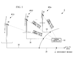
- Fig. 1 is a block diagram showing the entire configuration of a wind-power generation system according to this embodiment.
- a wind-power generation system 1 includes a plurality of wind turbines WTG1, WTG2, ..., WTGn (hereinafter denoted simply by the reference sign "WTG” when all wind turbines are referred to and denoted by the reference signs "WTG1", “WTG2", etc. when the individual wind turbines are referred to) and a central controller 10 for providing control commands to the individual wind turbines WTG.
- all wind-power generators WTG are variable-speed wind turbines.
- Each wind turbine WTG includes a generation system 20.
- the generation system 20 includes, as the main configuration thereof, for example, a generator, a variable-frequency converter excitation system capable of controlling the active power and the reactive power of the generator, and a wind turbine controller for providing a power command value to the variable-frequency converter excitation system.
- the powers output from the generation systems 20 of the individual wind turbines are supplied through respective power lines 30 to a utility grid via a common interconnection node A.
- the central controller 10 sets a power-factor command value for the interconnection node A based on a requested-power-factor command for the interconnection node A provided from a power management room managing grid power (for example, an electric utility).
- the power-factor command value is corrected using power factor correction levels set for the individual wind turbines WTG1, WTG2, ..., WTGn, and the corrected power-factor command values are transmitted to the respective wind turbines.
- WTG1, WTG2, ..., WTGn for example, a power management room managing grid power
- the generation system 20 of each wind turbine WTG1, WTG2, ..., WTGn sets an active-power command value and a reactive-power command value so as to satisfy the power-factor command value provided from the central controller 10.
- the wind turbine controller of the generation system 20 monitors the rotational speed of the generator to set an active-power command value corresponding to the rotational speed.
- a reactive-power command value satisfying the power-factor command value is determined from the active-power command value and the relational expression shown in equation (1) below.
- the wind turbine controller sets the reactive-power command value within the operating range depending on thermal constraints and voltage limitations.
- the setting may be such that the necessary reactive power is supplied by reducing the active power.
- P is the active power
- Q is the reactive power.
- the wind turbine controller provides the set active-power command value and the set reactive-power command value to the variable-frequency converter excitation system.
- the variable-frequency converter excitation system controls the generator based on the active-power command value and the reactive-power command value provided from the wind turbine controller.
- the power factor correction levels set for the individual wind turbines WTG1, WTG2, ..., WTGn described above will be described in detail.
- the above power factor correction levels are determined based on reactance components present between the individual wind turbines WTG1, WTG2, ..., WTGn and the interconnection node A.
- the lengths of the power lines 30 connecting the individual wind turbines WTG1, WTG2, ..., WTGn and the interconnection node A differ largely. Accordingly, the powers output from the wind turbines are affected by the reactances corresponding to the distances over the respective power lines 30 before reaching the interconnection node A.
- this embodiment takes into account the power variations, described above, due to the reactance components of the power lines 30 to correct the power-factor command value provided to the individual wind turbines using the power factor correction levels corresponding to the individual wind turbines, more specifically, the reactance components of the power lines 30 connecting the individual wind turbines and the interconnection node A.
- the reactances of the power lines between the individual wind turbines WTG1, WTG2, ..., WTGn and the interconnection node A be jx 1 , jx 2 , ..., jx i , ..., jx n , respectively, and the powers of the individual wind turbines at the interconnection node A are defined as P 1 '+jQ 1 ', P 2 '+jQ 2 ',..., P i '+jQ i ', ..., P n '+jQ n ', respectively.
- P i and Q i be known
- P i ' and Q i ' can be solved from equation (2) above.
- appropriate values are set by, for example, acquiring the active power P i and the reactive power Q i at the output end of the wind turbine over a past predetermined period of time (for example, one month, three months, or one year) and analyzing the acquired data.
- the power factor pf i at the output end of the wind turbine is represented by equation (3) below, and the power factor pf i ' at the interconnection node A is represented by equation (4) below.
- pf grid is the power-factor command value for the interconnection node A.
- the power factor correction levels ⁇ pf i determined for the individual wind turbines by the method described above are stored in a memory of the central controller 10 in association with the respective wind turbines and are used for correction of the power-factor command value in the operation of the wind turbines.
- the above power factor correction levels stored in the memory may be updated, for example, at predetermined time intervals (for example, every one year or three months).
- the active powers P i and the reactive powers Q i of the wind turbines may be set to appropriate values (for example, as described above, set using the analytical results of data over a past predetermined period of time), and these values may be substituted into the above equations to update the power factor correction levels for the individual wind turbines.
- the central controller 10 reads the power factor correction levels ⁇ pf i corresponding to the individual wind turbines WTG1, WTG2, ..., WTGn from the memory and corrects the power-factor command value pf grid using the power factor correction levels ⁇ pf i (Step SA2).
- the wind turbine controllers of the individual wind turbines WTG1, WTG2, ..., WTGn set active-power command values and reactive-power command values so as to satisfy the respective power-factor command values ⁇ pf 1 , ⁇ pf 2 , ..., ⁇ pf i , ..., ⁇ pf n received from the central controller 10 and provide the set of active-power command values and the set of reactive-power command values to the variable-frequency converter excitation systems.
- the variable-frequency converter excitation systems control the generators based on the provided active-power command values and the provided reactive-power command values.
- the central controller 10 detects the reactive power and the active power at the interconnection node A to calculate the actual power factor pf grid ' from the detected values.
- the difference between the calculated actual power factor pf grid ' and the power-factor command value pf grid is then calculated, and new power-factor command values are calculated so as to offset that difference and are provided as the next power-factor command values to the respective wind turbines (Step SA4) .
- the new power-factor command values are determined by further adding the difference between the actual power factor pf grid ' and the power-factor command value pf grid and the power factor correction levels ⁇ pf i to the power-factor command value pf grid , as in equation (6) below.
- the wind-power generation system 1 and the operation control method therefor determine power-factor command values appropriate for the individual wind turbines by correcting the power-factor command value for the interconnection node A using the power factor correction levels corresponding to the reactances present between the individual wind turbines and the interconnection node A, power factor control taking into account the reactances related to the power lines 30 can be performed in the individual wind turbines. This improves the accuracy of power factor control at the interconnection node A.
- FIG. 4 a second embodiment of the present invention will be described using Fig. 4 . While the case where all wind turbines are variable-speed wind turbines has been described in the first embodiment described above, the case where some wind turbines are fixed-speed wind turbines will be described in this embodiment.
- a wind-power generation system includes at least one fixed-speed wind turbine and at least one variable-speed wind turbine.
- the first to i-th wind turbines are variable-speed wind turbines
- the i+1-th to n-th wind turbines are fixed-speed wind turbines.
- the active powers P i ' and the reactive powers Q i ' at the interconnection node A are determined by power flow calculation based on the same procedure as in the first embodiment described above.
- ⁇ pf pf grid - pf fix ⁇ ⁇
- ⁇ pf a command value correction level
- a value obtained by adding the command value correction level ⁇ pf to the above power-factor command value pf grid is set as a new power-factor command value.
- the power-factor command values for the individual wind turbines are determined using the power factor correction levels ⁇ pf 1 , ⁇ pf 2 , ..., ⁇ pf i corresponding to the individual variable-speed wind turbines WTG1, WTG2, ..., WTGi, and the corrected power-factor command values are transmitted to the respective wind turbines.
- variable-speed wind turbines can absorb the variations in power factor due to the fixed-speed wind turbines. This improves the accuracy of power factor control even if fixed-speed wind turbines are included.
- the overall power factor of the fixed-speed wind turbines is determined and is used to correct the power-factor command value for the interconnection node A, and the corrected power-factor command value is further corrected using the power factor correction levels ⁇ pf i set for the individual variable-speed wind turbines; instead, for example, the power-factor command value corrected using the overall power factor of the fixed-speed wind turbines may be provided as a power-factor command value for the individual variable-speed wind turbines.
- the central controller 10 corrects the power-factor command value in the embodiments described above, the power-factor command value may instead be corrected, for example, in the individual wind turbines.
- a uniform power-factor command value is transmitted from the central controller 10 to the individual wind turbines, and the power-factor command value received from the central controller 10 is corrected in the individual wind turbines using the respective power factor correction levels possessed by the individual wind turbines.
- corrected power-factor command values etc. are transmitted from the central controller 10 by communication in this embodiment, a configuration may be employed in which, for example, the operator manually inputs and sets the power-factor command values to the respective wind turbines
Abstract
Description
- The present invention relates to wind-power generation systems and operation control methods therefor.
- In power factor control at an interconnection node of a wind farm, conventionally, a predetermined power-factor command value is determined by, for example, consultation with the grid operator so as to satisfy the range of, for example, a leading power factor of 0.95 to a lagging power factor of 0.95, and generation systems of individual wind turbines perform power factor control so as to maintain the determined predetermined power-factor command. In addition, if the power factor at the interconnection node deviates from the above range despite such control, the power factor at the interconnection node is adjusted by the opening/closing of a capacitor bank or reactors at a substation.
In addition, Patent Citation 1 discloses that a central controller for controlling the power at the interconnection node and so on transmits a uniform reactive power command to the individual wind turbines so that the individual wind turbines perform control based on the reactive power command. Patent Citation 1:
U.S. Pat. No. 7,166,928 , specification - To increase the voltage stability of a utility grid, the accuracy of power factor adjustment at an interconnection node must be improved. The conventional technique described above, however, is disadvantageous in that the accuracy of power factor adjustment cannot be further improved because a uniform reactive power command value is provided to the individual wind turbines.
- An object of the present invention is to provide a wind-power generation system and an operation control method therefor in which the accuracy of power factor adjustment can be improved.
- To solve the above problem, the present invention employs the following solutions.
A first aspect of the present invention is an operation control method for a wind-power generation system including a plurality of wind turbines and a central controller for providing control commands to the individual wind turbines, and output powers of the individual wind turbines are supplied to a utility grid via a common interconnection node. Power-factor command values corresponding to the individual wind turbines are determined by correcting a predetermined power-factor command value for the interconnection node using power factor correction levels set for the individual wind turbines. - According to the present invention, because the predetermined power-factor command value for the interconnection node is corrected using the power factor correction levels corresponding to the individual wind turbines, different power-factor command values can be set for the individual wind turbines. This allows power factor control of the individual wind turbines based on appropriate power-factor command values taking into account, for example, the properties related to the individual wind turbines, thus improving the accuracy of power factor control at the grid node.
- In the above operation control method for the wind-power generation system, the power factor correction levels may be determined based on reactance components present between the individual wind turbines and the interconnection node.
- Thus, because the power-factor command values for the individual wind turbines are determined using the power factor correction levels taking into account the reactance components present between the wind turbines and the interconnection node, the actual power factor at the interconnection node can be efficiently adjusted to the predetermined power-factor command value.
For example, if simple feedback control is performed to adjust the actual power factor at the interconnection node to the power-factor command value without taking into account the reactance components present between the individual wind turbines and the interconnection node, it is possible to adjust the power factors at output ends of generation systems of the individual wind turbines to the power-factor command value provided to the individual wind turbines, although it is difficult to adjust the power factor at the interconnection node to the predetermined power-factor command value. This is because the power factor varies depending on, for example, the reactances of power lines connecting the output ends of the wind turbines to the interconnection node. In this respect, according to the present invention, the power factor at the interconnection node can be controlled efficiently and accurately because the individual wind turbines are controlled based on the power-factor command values taking into account the reactance components present between the individual wind turbines and the interconnection node. - A second aspect of the present invention is an operation control method for a wind-power generation system including a plurality of wind turbines and a central controller for providing control commands to the individual wind turbines, and outputs of the individual wind turbines are supplied to a utility grid via a common interconnection node. If the plurality of wind turbines include both variable-speed wind turbines and fixed-speed wind turbines, the overall power factor of the fixed-speed wind turbines at the interconnection node is calculated, the difference between the calculated power factor and a predetermined power-factor command value for the interconnection node is calculated, the predetermined power-factor command value is corrected using the calculated difference, and power-factor command values for the individual variable-speed wind turbines are determined based on the corrected predetermined power-factor command value.
- According to the above method, because the power-factor command values for the variable-speed wind turbines are determined by taking into account variations in power factor due to the fixed-speed wind turbines, the variations in power factor due to the fixed-speed wind turbines can be absorbed by power factor control of the variable-speed wind turbines.
This improves the accuracy of power factor control at the interconnection node even if fixed-speed wind turbines and variable-speed wind turbines are both present. - In the above operation control method for the wind-power generation system, the power-factor command values corresponding to the individual variable-speed wind turbines may be determined by correcting the corrected predetermined power-factor command value using power factor correction levels set for the individual variable-speed wind turbines.
- Thus, because the power-factor command values for the individual variable-speed wind turbines are determined by further correcting the predetermined power-factor command value for the interconnection node, corrected by taking into account the variations in the power factors of the fixed-speed wind turbines, using the power factor correction levels set for the individual variable-speed wind turbines, different power-factor command values can be set for the individual variable-speed wind turbines. This allows power factor control of the individual variable-speed wind turbines based on appropriate power-factor command values taking into account, for example, the properties related to the individual variable-speed wind turbines, thus further improving the accuracy of power factor control at the interconnection node.
- In the above operation control method for the wind-power generation system, the power factor correction levels corresponding to the individual variable-speed wind turbines may be determined based on reactance components present between the individual variable-speed wind turbines and the interconnection node.
- Thus, because the power-factor command values for the individual variable-speed wind turbines are determined by taking into account the reactance components present between the wind turbines and the interconnection node, the actual power factor at the interconnection node can be efficiently adjusted to the power-factor command value.
- A third aspect of the present invention is a wind-power generation system including a plurality of wind turbines and a central controller for providing control commands to the individual wind turbines, and output powers of the individual wind turbines are supplied to a utility grid via a common interconnection node. Power-factor command values corresponding to the individual wind turbines are determined by correcting a predetermined power-factor command value for the interconnection node using power factor correction levels set for the individual wind turbines.
- A fourth aspect of the present invention is a wind-power generation system including a plurality of wind turbines and a central controller for providing control commands to the individual wind turbines, and outputs of the individual wind turbines are supplied to a utility grid via a common interconnection node. If the plurality of wind turbines include both variable-speed wind turbines and fixed-speed wind turbines, the central controller calculates the overall power factor of the fixed-speed wind turbines at the interconnection node, calculates the difference between the calculated power factor and a predetermined power-factor command value for the interconnection node, corrects the predetermined power-factor command value using the calculated difference, and determines power-factor command values for the individual variable-speed wind turbines based on the corrected predetermined power-factor command value.
- The present invention provides the advantage of improving the accuracy of power factor adjustment.
-
- [
FIG. 1] Fig. 1 is a diagram showing the entire configuration of a wind-power generation system according to a first embodiment of the present invention. - [
FIG. 2] Fig. 2 is a diagram illustrating power factor correction levels according to the first embodiment of the present invention. - [
FIG. 3] Fig. 3 is a flowchart showing a procedure of an operation control method for the wind-power generation system according to the first embodiment of the present invention. - [
FIG. 4] Fig. 4 is a diagram illustrating an operation control method for a wind-power generation system according to a second embodiment of the present invention. -
- 1: wind-power generation system
- 10: central controller
- 20: generation system
- 30: power line
- WTG1, WTG1, WTGn: wind turbine
- Individual embodiments of wind-power generation systems and operation control methods thereof according to the present invention will be described below with reference to the drawings.
-
Fig. 1 is a block diagram showing the entire configuration of a wind-power generation system according to this embodiment. As shown inFig. 1 , a wind-power generation system 1 includes a plurality of wind turbines WTG1, WTG2, ..., WTGn (hereinafter denoted simply by the reference sign "WTG" when all wind turbines are referred to and denoted by the reference signs "WTG1", "WTG2", etc. when the individual wind turbines are referred to) and acentral controller 10 for providing control commands to the individual wind turbines WTG. In this embodiment, all wind-power generators WTG are variable-speed wind turbines. - Each wind turbine WTG includes a
generation system 20. Thegeneration system 20 includes, as the main configuration thereof, for example, a generator, a variable-frequency converter excitation system capable of controlling the active power and the reactive power of the generator, and a wind turbine controller for providing a power command value to the variable-frequency converter excitation system.
The powers output from thegeneration systems 20 of the individual wind turbines are supplied throughrespective power lines 30 to a utility grid via a common interconnection node A. - The
central controller 10 sets a power-factor command value for the interconnection node A based on a requested-power-factor command for the interconnection node A provided from a power management room managing grid power (for example, an electric utility). The power-factor command value is corrected using power factor correction levels set for the individual wind turbines WTG1, WTG2, ..., WTGn, and the corrected power-factor command values are transmitted to the respective wind turbines. Here the details of the power factor correction levels set for the individual wind turbines will be described later. - The
generation system 20 of each wind turbine WTG1, WTG2, ..., WTGn sets an active-power command value and a reactive-power command value so as to satisfy the power-factor command value provided from thecentral controller 10. Specifically, the wind turbine controller of thegeneration system 20 monitors the rotational speed of the generator to set an active-power command value corresponding to the rotational speed. In addition, a reactive-power command value satisfying the power-factor command value is determined from the active-power command value and the relational expression shown in equation (1) below. At this time, the wind turbine controller sets the reactive-power command value within the operating range depending on thermal constraints and voltage limitations. In addition, if the power-factor command is given priority, the setting may be such that the necessary reactive power is supplied by reducing the active power. -
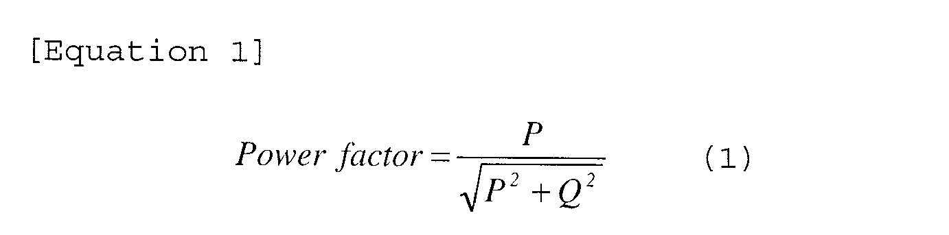
- In equation (1) above, P is the active power, and Q is the reactive power.
The wind turbine controller provides the set active-power command value and the set reactive-power command value to the variable-frequency converter excitation system. The variable-frequency converter excitation system controls the generator based on the active-power command value and the reactive-power command value provided from the wind turbine controller.
With the above power factor control, active powers and reactive powers satisfying the power-factor command values provided to the individual wind turbines are output from the respective wind turbines WTG and are supplied to the common interconnection node A through thepower lines 30. - Next, the power factor correction levels set for the individual wind turbines WTG1, WTG2, ..., WTGn described above will be described in detail.
The above power factor correction levels are determined based on reactance components present between the individual wind turbines WTG1, WTG2, ..., WTGn and the interconnection node A. In a wind farm having many wind turbines, for example, the lengths of thepower lines 30 connecting the individual wind turbines WTG1, WTG2, ..., WTGn and the interconnection node A differ largely. Accordingly, the powers output from the wind turbines are affected by the reactances corresponding to the distances over therespective power lines 30 before reaching the interconnection node A. - As a result, for example, if a uniform power-factor command value is provided to the individual wind turbines, variations in the reactive power at the interconnection node A can occur and decrease the power factor accuracy. In that respect, this embodiment takes into account the power variations, described above, due to the reactance components of the
power lines 30 to correct the power-factor command value provided to the individual wind turbines using the power factor correction levels corresponding to the individual wind turbines, more specifically, the reactance components of thepower lines 30 connecting the individual wind turbines and the interconnection node A. - First, as shown in
Fig. 2 , let the powers at the output ends of the individual wind turbines WTG1, WTG2, ..., WTG1 , ..., WTGn be P1+jQ1, P2+jQ2, ..., Pi+jQi, ..., Pn+jQn, respectively. In addition, let the reactances of the power lines between the individual wind turbines WTG1, WTG2, ..., WTGn and the interconnection node A be jx1, jx2, ..., jxi, ..., jxn, respectively, and the powers of the individual wind turbines at the interconnection node A are defined as P1'+jQ1', P2'+jQ2',..., Pi'+jQi', ..., Pn'+jQn', respectively. - Next, power flow calculation is performed for each wind turbine. Here the i-th wind turbine will be described as an example. For convenience, let interconnection node voltage Vgrid = 1 pu and phase angle δgrid = 0. In addition, let the direction from each wind turbine toward the interconnection node A be positive in sign for both the active power P and the reactive power Q. The sign of the power factor also corresponds thereto; for example, power factor pf > 0 if P > 0 and Q > 0, and power factor pf < 0 if P > 0 and Q < 0.
Under such conditions, the active power Pi and the reactive power Qi at the output end of the wind turbine GTWi and the active power Pi' and the reactive power Qi' at the interconnection node A are represented, respectively, as follows. -

- In this power flow calculation, the active powers have the same value, namely, Pi = Pi', because only the reactance components of the
power lines 30 are taken into account. Letting Pi and Qi be known, Pi' and Qi' can be solved from equation (2) above.
As Pi and Qi, appropriate values (for example, averages) are set by, for example, acquiring the active power Pi and the reactive power Qi at the output end of the wind turbine over a past predetermined period of time (for example, one month, three months, or one year) and analyzing the acquired data. - The power factor pfi at the output end of the wind turbine is represented by equation (3) below, and the power factor pfi' at the interconnection node A is represented by equation (4) below.
-


- As a result, the power factor correction level Δpfi for the i-th wind turbine can be determined by equation (5) below:

In equation (5) above, pfgrid is the power-factor command value for the interconnection node A. - The power factor correction levels Δpfi determined for the individual wind turbines by the method described above are stored in a memory of the
central controller 10 in association with the respective wind turbines and are used for correction of the power-factor command value in the operation of the wind turbines.
The above power factor correction levels stored in the memory may be updated, for example, at predetermined time intervals (for example, every one year or three months). For updating, the active powers Pi and the reactive powers Qi of the wind turbines may be set to appropriate values (for example, as described above, set using the analytical results of data over a past predetermined period of time), and these values may be substituted into the above equations to update the power factor correction levels for the individual wind turbines. - Next, an operation control method for the wind-power generation system having the above configuration will be described.
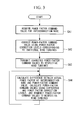
First, upon acquisition of the power-factor command value pfgrid for the interconnection node (Step SA1 inFig. 3 ), thecentral controller 10 reads the power factor correction levels Δpfi corresponding to the individual wind turbines WTG1,
WTG2, ..., WTGn from the memory and corrects the power-factor command value pfgrid using the power factor correction levels Δpfi (Step SA2). The corrected power-factor command values pfi (= pfgrid + Δpfi) are transmitted to the respective wind turbines WTG1, WTG2, ..., WTGn (Step SA3). - The wind turbine controllers of the individual wind turbines WTG1, WTG2, ..., WTGn set active-power command values and reactive-power command values so as to satisfy the respective power-factor command values Δpf1, Δpf2, ..., Δpfi, ..., Δpfn received from the
central controller 10 and provide the set of active-power command values and the set of reactive-power command values to the variable-frequency converter excitation systems. The variable-frequency converter excitation systems control the generators based on the provided active-power command values and the provided reactive-power command values. Thus, the active powers and the reactive powers satisfying the power-factor command values corresponding to the individual wind turbines are output from the respective wind turbines and are supplied to the common interconnection node A through thepower lines 30. - The
central controller 10 detects the reactive power and the active power at the interconnection node A to calculate the actual power factor pfgrid' from the detected values. The difference between the calculated actual power factor pfgrid' and the power-factor command value pfgrid is then calculated, and new power-factor command values are calculated so as to offset that difference and are provided as the next power-factor command values to the respective wind turbines (Step SA4) .
The new power-factor command values are determined by further adding the difference between the actual power factor pfgrid' and the power-factor command value pfgrid and the power factor correction levels Δpfi to the power-factor command value pfgrid, as in equation (6) below. -

In this way, feedback control can be performed to stabilize the power factor at the interconnection node A. - As described above, because the wind-
power generation system 1 and the operation control method therefor according to this embodiment determine power-factor command values appropriate for the individual wind turbines by correcting the power-factor command value for the interconnection node A using the power factor correction levels corresponding to the reactances present between the individual wind turbines and the interconnection node A, power factor control taking into account the reactances related to thepower lines 30 can be performed in the individual wind turbines. This improves the accuracy of power factor control at the interconnection node A. - Next, a second embodiment of the present invention will be described using
Fig. 4 .
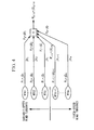
While the case where all wind turbines are variable-speed wind turbines has been described in the first embodiment described above, the case where some wind turbines are fixed-speed wind turbines will be described in this embodiment. - A wind-power generation system according to this embodiment includes at least one fixed-speed wind turbine and at least one variable-speed wind turbine. As shown in
Fig. 4 , for example, the first to i-th wind turbines are variable-speed wind turbines, whereas the i+1-th to n-th wind turbines are fixed-speed wind turbines. In this case, first, the active powers Pi' and the reactive powers Qi' at the interconnection node A are determined by power flow calculation based on the same procedure as in the first embodiment described above. - Subsequently, the sums of the active powers and the reactive powers of the fixed-speed wind turbines alone at the interconnection node A are determined as shown in equations (7) and (8) below.
-


- Subsequently, the above sums of the active powers and the reactive powers are used to calculate the overall power factor affix' of the fixed-speed wind turbines.
-

- Next, the difference between the power-factor command value for the interconnection node A and the above overall power factor pffix' of the fixed-speed wind turbines is calculated.

To absorb that difference in the variable-speed wind turbines, Δpf is set as a command value correction level, and a value obtained by adding the command value correction level Δpf to the above power-factor command value pfgrid is set as a new power-factor command value. Based on the power-factor command value, as in the first embodiment described above, the power-factor command values for the individual wind turbines are determined using the power factor correction levels Δpf1, Δpf2, ..., Δpfi corresponding to the individual variable-speed wind turbines WTG1, WTG2, ..., WTGi, and the corrected power-factor command values are transmitted to the respective wind turbines. - As described above, if fixed-speed wind turbines and variable-speed wind turbines are both present, because the wind-power generation system and the operation control method therefor according to this embodiment determine power-factor command values for the variable-speed wind turbines by taking into account variations in the power factors of the fixed-speed wind turbines, the variable-speed wind turbines can absorb the variations in power factor due to the fixed-speed wind turbines. This improves the accuracy of power factor control even if fixed-speed wind turbines are included.
- In this embodiment, the overall power factor of the fixed-speed wind turbines is determined and is used to correct the power-factor command value for the interconnection node A, and the corrected power-factor command value is further corrected using the power factor correction levels Δpfi set for the individual variable-speed wind turbines; instead, for example, the power-factor command value corrected using the overall power factor of the fixed-speed wind turbines may be provided as a power-factor command value for the individual variable-speed wind turbines. Although in this case variations in power factor due to reactors present between the individual variable-speed wind turbines and the interconnection node A are not offset, a considerable advantage can be achieved in that the variations in power factor due to the fixed-speed wind turbines can be offset.
- Although the embodiments of the present invention have been described above in detail with reference to the drawings, specific configurations are not limited to those of the embodiments; design changes etc. are encompassed without departing from the spirit of the present invention.
- For example, although the
central controller 10 corrects the power-factor command value in the embodiments described above, the power-factor command value may instead be corrected, for example, in the individual wind turbines. In this case, a uniform power-factor command value is transmitted from thecentral controller 10 to the individual wind turbines, and the power-factor command value received from thecentral controller 10 is corrected in the individual wind turbines using the respective power factor correction levels possessed by the individual wind turbines. - In addition, although the corrected power-factor command values etc. are transmitted from the
central controller 10 by communication in this embodiment, a configuration may be employed in which, for example, the operator manually inputs and sets the power-factor command values to the respective wind turbines
Claims (7)
- An operation control method for a wind-power generation system comprising a plurality of wind turbines and a central controller for providing control commands to the individual wind turbines, output powers of the individual wind turbines being supplied to a utility grid via a common interconnection node,
wherein power-factor command values corresponding to the individual wind turbines are determined by correcting a predetermined power-factor command value for the interconnection node using power factor correction levels set for the individual wind turbines. - The operation control method for the wind-power generation system according to Claim 1, wherein the power factor correction levels are determined based on reactance components present between the individual wind turbines and the interconnection node.
- An operation control method for a wind-power generation system comprising a plurality of wind turbines and a central controller for providing control commands to the individual wind turbines, outputs of the individual wind turbines being supplied to a utility grid via a common interconnection node, wherein
if the plurality of wind turbines include both variable-speed wind turbines and fixed-speed wind turbines, the overall power factor of the fixed-speed wind turbines at the interconnection node is calculated;
the difference between the calculated power factor and a predetermined power-factor command value for the interconnection node is calculated;
the predetermined power-factor command value is corrected using the calculated difference; and
power-factor command values for the individual variable-speed wind turbines are determined based on the corrected predetermined power-factor command value. - The operation control method for the wind-power generation system according to Claim 3, wherein the power-factor command values corresponding to the individual variable-speed wind turbines are determined by correcting the corrected predetermined power-factor command value using power factor correction levels set for the individual variable-speed wind turbines.
- The operation control method for the wind-power generation system according to Claim 4, wherein the power factor correction levels corresponding to the individual variable-speed wind turbines are determined based on reactance components present between the individual variable-speed wind turbines and the interconnection node.
- A wind-power generation system comprising a plurality of wind turbines and a central controller for providing control commands to the individual wind turbines, output powers of the individual wind turbines being supplied to a utility grid via a common interconnection node,
wherein power-factor command values corresponding to the individual wind turbines are determined by correcting a predetermined power-factor command value for the interconnection node using power factor correction levels set for the individual wind turbines. - A wind-power generation system comprising a plurality of wind turbines and a central controller for providing control commands to the individual wind turbines, outputs of the individual wind turbines being supplied to a utility grid via a common interconnection node,
wherein, if the plurality of wind turbines include both variable-speed wind turbines and fixed-speed wind turbines,
the central controller:calculates the overall power factor of the fixed-speed wind turbines at the interconnection node;calculates the difference between the calculated power factor and a predetermined power-factor command value for the interconnection node;corrects the predetermined power-factor command value using the calculated difference; anddetermines power-factor command values for the individual variable-speed wind turbines based on the corrected predetermined power-factor command value.
Applications Claiming Priority (1)
| Application Number | Priority Date | Filing Date | Title |
|---|---|---|---|
| PCT/JP2007/074121 WO2009078076A1 (en) | 2007-12-14 | 2007-12-14 | Wind power generation system and its operation control method |
Publications (2)
| Publication Number | Publication Date |
|---|---|
| EP2221958A1 true EP2221958A1 (en) | 2010-08-25 |
| EP2221958A4 EP2221958A4 (en) | 2015-09-02 |
Family
ID=40795202
Family Applications (1)
| Application Number | Title | Priority Date | Filing Date |
|---|---|---|---|
| EP07850625.0A Withdrawn EP2221958A4 (en) | 2007-12-14 | 2007-12-14 | Wind power generation system and its operation control method |
Country Status (9)
| Country | Link |
|---|---|
| US (2) | US8355829B2 (en) |
| EP (1) | EP2221958A4 (en) |
| JP (1) | JP5039793B2 (en) |
| KR (1) | KR101176394B1 (en) |
| CN (1) | CN101809856B (en) |
| AU (1) | AU2007362452B2 (en) |
| BR (1) | BRPI0722046A2 (en) |
| CA (1) | CA2696844A1 (en) |
| WO (1) | WO2009078076A1 (en) |
Cited By (4)
| Publication number | Priority date | Publication date | Assignee | Title |
|---|---|---|---|---|
| WO2015086021A1 (en) * | 2013-12-11 | 2015-06-18 | Vestas Wind Systems A/S | A wind power plant, and a method for increasing the reactive power capability of a wind power plant |
| EP2858199A4 (en) * | 2012-05-31 | 2016-05-11 | Mitsubishi Heavy Ind Ltd | Voltage control device, control method thereof and voltage control program |
| WO2016070882A1 (en) * | 2014-11-03 | 2016-05-12 | Vestas Wind Systems A/S | Method of controlling active power generation of a wind power plant and wind power plant |
| CN105743133A (en) * | 2016-05-03 | 2016-07-06 | 电子科技大学 | Active power control method for wind power plant participated power grid frequency modulation |
Families Citing this family (24)
| Publication number | Priority date | Publication date | Assignee | Title |
|---|---|---|---|---|
| US6911501B1 (en) | 2004-01-21 | 2005-06-28 | Bayer Materialscience Llc | Process for preparing aspartates |
| US7642666B2 (en) * | 2006-11-02 | 2010-01-05 | Hitachi, Ltd. | Wind power generation apparatus, wind power generation system and power system control apparatus |
| US8527104B2 (en) * | 2007-12-14 | 2013-09-03 | Mitsubishi Heavy Industries, Ltd. | Wind turbine generator system and operation control method therefor |
| JP5388769B2 (en) * | 2009-09-09 | 2014-01-15 | 株式会社日立製作所 | Wind power generation system, control method, control device, and program |
| JP5320311B2 (en) * | 2010-01-18 | 2013-10-23 | 三菱重工業株式会社 | Variable speed generator and control method thereof |
| EP2397688A1 (en) * | 2010-06-16 | 2011-12-21 | Siemens Aktiengesellschaft | Electric power control system and electric power facility comprising the electric power control system |
| US8121738B2 (en) * | 2010-08-26 | 2012-02-21 | General Electric Company | Method and apparatus for controlling wind turbine electric power generation |
| JP5627529B2 (en) * | 2011-04-01 | 2014-11-19 | 三菱重工業株式会社 | Wind turbine generator control device, wind turbine generator, wind farm, and wind turbine generator control method |
| GB2493711B (en) * | 2011-08-12 | 2018-04-25 | Openhydro Ip Ltd | Method and system for controlling hydroelectric turbines |
| DK2607692T3 (en) * | 2011-12-22 | 2015-05-04 | Siemens Ag | Method for determining a voltage limiting range |
| JP5886658B2 (en) * | 2012-03-02 | 2016-03-16 | 京セラ株式会社 | Control device and control method |
| WO2014083685A1 (en) * | 2012-11-30 | 2014-06-05 | 三菱重工業株式会社 | Wind farm output control device and output control method |
| EP2908004B1 (en) * | 2013-01-15 | 2016-10-12 | Mitsubishi Heavy Industries, Ltd. | Wind power generation facility, method for operating same, and wind farm control device |
| KR101480533B1 (en) * | 2013-06-28 | 2015-01-08 | 한국전력공사 | Apparatus and method for interconnecting distributed generations into power grid |
| KR102130093B1 (en) * | 2013-07-15 | 2020-07-03 | 두산중공업 주식회사 | Wind Farm Controller and Reactive Power Dispatch Method Thereof, and System using the same |
| DE102013224411A1 (en) * | 2013-11-26 | 2015-05-28 | Siemens Aktiengesellschaft | Method for the computer-aided configuration of an electrical power network |
| CN103605360B (en) * | 2013-12-02 | 2016-08-17 | 国家电网公司 | A kind of test system and method for wind farm power control strategy |
| US10367354B2 (en) * | 2015-01-12 | 2019-07-30 | Dominion Energy, Inc. | Systems and methods for volt-ampere reactive control and optimization |
| US10386395B1 (en) * | 2015-06-03 | 2019-08-20 | University Of Southern California | Subcircuit physical level power monitoring technology for real-time hardware systems and simulators |
| WO2018140794A1 (en) * | 2017-01-27 | 2018-08-02 | Level 3 Communications, Llc | System and method for scrubbing dns in a telecommunications network to mitigate attacks |
| FR3062750B1 (en) * | 2017-02-03 | 2019-06-07 | Moteurs Leroy-Somer | METHOD FOR CONTROLLING ALTERNATORS IN PARALLEL FOR REACTIVE CHARGE DISTRIBUTION |
| US10767630B1 (en) * | 2019-05-28 | 2020-09-08 | General Electric Company | System and method for operating a wind farm during low wind speeds |
| JP7250632B2 (en) * | 2019-06-27 | 2023-04-03 | 株式会社日立製作所 | Integrated control device and integrated control method for renewable energy power generation system |
| EP3852211A1 (en) * | 2020-01-16 | 2021-07-21 | Nordex Energy SE & Co. KG | Method for controlling the output of a wind farm |
Family Cites Families (20)
| Publication number | Priority date | Publication date | Assignee | Title |
|---|---|---|---|---|
| US5083039B1 (en) * | 1991-02-01 | 1999-11-16 | Zond Energy Systems Inc | Variable speed wind turbine |
| JPH08126204A (en) * | 1994-10-21 | 1996-05-17 | Mitsubishi Electric Corp | System stabilizer |
| JPH1141990A (en) * | 1997-07-17 | 1999-02-12 | Mitsubishi Heavy Ind Ltd | Power factor control device for power plant |
| JP2000078896A (en) | 1998-08-28 | 2000-03-14 | Hitachi Engineering & Services Co Ltd | Wind power generating system |
| US6682554B2 (en) * | 1998-09-05 | 2004-01-27 | Jomed Gmbh | Methods and apparatus for a stent having an expandable web structure |
| DE19948196A1 (en) | 1999-10-06 | 2001-05-17 | Aloys Wobben | Process for operating a wind farm |
| JP3607561B2 (en) * | 2000-03-22 | 2005-01-05 | 日本碍子株式会社 | Constant power factor control method for reactive power compensator |
| NO20001641L (en) * | 2000-03-29 | 2001-10-01 | Abb Research Ltd | Wind power plants |
| US7002321B2 (en) * | 2001-06-05 | 2006-02-21 | Mcdaniel William D | Automatic power factor correction using power measurement chip |
| US6924565B2 (en) | 2003-08-18 | 2005-08-02 | General Electric Company | Continuous reactive power support for wind turbine generators |
| US7119452B2 (en) | 2003-09-03 | 2006-10-10 | General Electric Company | Voltage control for wind generators |
| US7288921B2 (en) * | 2004-06-25 | 2007-10-30 | Emerson Process Management Power & Water Solutions, Inc. | Method and apparatus for providing economic analysis of power generation and distribution |
| DE102004048341A1 (en) * | 2004-10-01 | 2006-04-13 | Repower Systems Ag | Wind farm with robust reactive power regulation and method of operation |
| JP4495001B2 (en) | 2005-02-17 | 2010-06-30 | 三菱重工業株式会社 | Power generation system |
| WO2006120033A2 (en) * | 2005-05-13 | 2006-11-16 | Siemens Ag | Wind farm power control system |
| US8649911B2 (en) * | 2005-06-03 | 2014-02-11 | General Electric Company | System and method for operating a wind farm under high wind speed conditions |
| US7573160B2 (en) * | 2005-07-20 | 2009-08-11 | General Electric Company | Methods and apparatus for controlling windfarms and windfarms controlled thereby |
| JP4899800B2 (en) * | 2006-02-28 | 2012-03-21 | 株式会社日立製作所 | Wind turbine generator, wind turbine generator system and power system controller |
| US7505833B2 (en) * | 2006-03-29 | 2009-03-17 | General Electric Company | System, method, and article of manufacture for controlling operation of an electrical power generation system |
| US8527104B2 (en) | 2007-12-14 | 2013-09-03 | Mitsubishi Heavy Industries, Ltd. | Wind turbine generator system and operation control method therefor |
-
2007
- 2007-12-14 EP EP07850625.0A patent/EP2221958A4/en not_active Withdrawn
- 2007-12-14 KR KR1020107005958A patent/KR101176394B1/en not_active IP Right Cessation
- 2007-12-14 CN CN200780100901.6A patent/CN101809856B/en active Active
- 2007-12-14 AU AU2007362452A patent/AU2007362452B2/en not_active Ceased
- 2007-12-14 JP JP2009546090A patent/JP5039793B2/en active Active
- 2007-12-14 US US12/673,889 patent/US8355829B2/en active Active
- 2007-12-14 WO PCT/JP2007/074121 patent/WO2009078076A1/en active Application Filing
- 2007-12-14 BR BRPI0722046-4A2A patent/BRPI0722046A2/en not_active IP Right Cessation
- 2007-12-14 CA CA2696844A patent/CA2696844A1/en not_active Abandoned
-
2012
- 2012-12-10 US US13/709,755 patent/US8676392B2/en not_active Expired - Fee Related
Cited By (10)
| Publication number | Priority date | Publication date | Assignee | Title |
|---|---|---|---|---|
| EP2858199A4 (en) * | 2012-05-31 | 2016-05-11 | Mitsubishi Heavy Ind Ltd | Voltage control device, control method thereof and voltage control program |
| WO2015086021A1 (en) * | 2013-12-11 | 2015-06-18 | Vestas Wind Systems A/S | A wind power plant, and a method for increasing the reactive power capability of a wind power plant |
| CN105850000A (en) * | 2013-12-11 | 2016-08-10 | 维斯塔斯风力系统有限公司 | A wind power plant, and a method for increasing the reactive power capability of a wind power plant |
| EP3080887B1 (en) | 2013-12-11 | 2019-04-03 | Vestas Wind Systems A/S | A wind power plant, and a method for increasing the reactive power capability of a wind power plant |
| CN105850000B (en) * | 2013-12-11 | 2019-05-07 | 维斯塔斯风力系统有限公司 | Increase reactive power capacity method, wind power plant and computer readable storage medium |
| US10320196B2 (en) | 2013-12-11 | 2019-06-11 | Vestas Wind Systems A/S | Wind power plant, and a method for increasing the reactive power capability of a wind power plant |
| EP3080887B2 (en) † | 2013-12-11 | 2023-08-23 | Vestas Wind Systems A/S | A wind power plant, and a method for increasing the reactive power capability of a wind power plant |
| WO2016070882A1 (en) * | 2014-11-03 | 2016-05-12 | Vestas Wind Systems A/S | Method of controlling active power generation of a wind power plant and wind power plant |
| US10968891B2 (en) | 2014-11-03 | 2021-04-06 | Vestas Wind Systems A/S | Method of controlling active power generation of a wind power plant and wind power plant |
| CN105743133A (en) * | 2016-05-03 | 2016-07-06 | 电子科技大学 | Active power control method for wind power plant participated power grid frequency modulation |
Also Published As
| Publication number | Publication date |
|---|---|
| EP2221958A4 (en) | 2015-09-02 |
| AU2007362452A1 (en) | 2009-06-25 |
| CN101809856B (en) | 2014-02-26 |
| JP5039793B2 (en) | 2012-10-03 |
| US8676392B2 (en) | 2014-03-18 |
| JPWO2009078076A1 (en) | 2011-04-28 |
| BRPI0722046A2 (en) | 2014-03-25 |
| CN101809856A (en) | 2010-08-18 |
| CA2696844A1 (en) | 2009-06-25 |
| US20100250012A1 (en) | 2010-09-30 |
| KR101176394B1 (en) | 2012-08-27 |
| WO2009078076A1 (en) | 2009-06-25 |
| AU2007362452B2 (en) | 2012-12-20 |
| KR20100043286A (en) | 2010-04-28 |
| US8355829B2 (en) | 2013-01-15 |
| US20130093186A1 (en) | 2013-04-18 |
Similar Documents
| Publication | Publication Date | Title |
|---|---|---|
| EP2221958A1 (en) | Wind power generation system and its operation control method | |
| EP2221957B1 (en) | Wind power generation system and its operation control method | |
| US8364323B2 (en) | Wind power generation system and operation control method thereof | |
| US9932966B2 (en) | Method for avoiding voltage instability in an electrical grid of an offshore wind park | |
| US9997922B2 (en) | Method for feeding electrical power into an electrical supply network | |
| US20180003153A1 (en) | Calibrating a wind vane of a wind turbine | |
| EP2553788B1 (en) | Method of operating a wind turbine, wind turbine, wind turbine controlling system, and processing system | |
| EP1508951B1 (en) | Continuous reactive power support for wind turbine generators | |
| US8355824B2 (en) | Wind turbine generator and method of controlling the same | |
| US9859710B2 (en) | Line impedance compensation system | |
| EP3669433B1 (en) | Improvements relating to reactive power control in wind power plants |
Legal Events
| Date | Code | Title | Description |
|---|---|---|---|
| PUAI | Public reference made under article 153(3) epc to a published international application that has entered the european phase |
Free format text: ORIGINAL CODE: 0009012 |
|
| 17P | Request for examination filed |
Effective date: 20100216 |
|
| AK | Designated contracting states |
Kind code of ref document: A1 Designated state(s): AT BE BG CH CY CZ DE DK EE ES FI FR GB GR HU IE IS IT LI LT LU LV MC MT NL PL PT RO SE SI SK TR |
|
| AX | Request for extension of the european patent |
Extension state: AL BA HR MK RS |
|
| DAX | Request for extension of the european patent (deleted) | ||
| RA4 | Supplementary search report drawn up and despatched (corrected) |
Effective date: 20150731 |
|
| RIC1 | Information provided on ipc code assigned before grant |
Ipc: H02P 9/00 20060101AFI20150727BHEP Ipc: H02J 3/18 20060101ALI20150727BHEP Ipc: F03D 7/04 20060101ALI20150727BHEP Ipc: H02J 3/38 20060101ALI20150727BHEP Ipc: H02P 23/00 20060101ALI20150727BHEP Ipc: F03D 7/02 20060101ALI20150727BHEP |
|
| 17Q | First examination report despatched |
Effective date: 20160707 |
|
| STAA | Information on the status of an ep patent application or granted ep patent |
Free format text: STATUS: THE APPLICATION IS DEEMED TO BE WITHDRAWN |
|
| 18D | Application deemed to be withdrawn |
Effective date: 20170118 |