EP3852211A1 - Method for controlling the output of a wind farm - Google Patents
Method for controlling the output of a wind farm Download PDFInfo
- Publication number
- EP3852211A1 EP3852211A1 EP20152238.0A EP20152238A EP3852211A1 EP 3852211 A1 EP3852211 A1 EP 3852211A1 EP 20152238 A EP20152238 A EP 20152238A EP 3852211 A1 EP3852211 A1 EP 3852211A1
- Authority
- EP
- European Patent Office
- Prior art keywords
- power
- reactive power
- soll
- wind
- setpoint
- Prior art date
- Legal status (The legal status is an assumption and is not a legal conclusion. Google has not performed a legal analysis and makes no representation as to the accuracy of the status listed.)
- Pending
Links
- 238000000034 method Methods 0.000 title claims abstract description 57
- 230000001105 regulatory effect Effects 0.000 claims abstract description 54
- 238000009434 installation Methods 0.000 claims description 39
- 230000001419 dependent effect Effects 0.000 claims description 3
- 230000005540 biological transmission Effects 0.000 description 6
- 238000013459 approach Methods 0.000 description 4
- 238000006243 chemical reaction Methods 0.000 description 2
- 238000010586 diagram Methods 0.000 description 2
- 230000010355 oscillation Effects 0.000 description 2
- 230000010363 phase shift Effects 0.000 description 2
- 241000881711 Acipenser sturio Species 0.000 description 1
- 230000001276 controlling effect Effects 0.000 description 1
- 230000003247 decreasing effect Effects 0.000 description 1
- 238000006073 displacement reaction Methods 0.000 description 1
- 230000035484 reaction time Effects 0.000 description 1
Images


Classifications
-
- H—ELECTRICITY
- H02—GENERATION; CONVERSION OR DISTRIBUTION OF ELECTRIC POWER
- H02J—CIRCUIT ARRANGEMENTS OR SYSTEMS FOR SUPPLYING OR DISTRIBUTING ELECTRIC POWER; SYSTEMS FOR STORING ELECTRIC ENERGY
- H02J3/00—Circuit arrangements for AC mains or AC distribution networks
- H02J3/18—Arrangements for adjusting, eliminating or compensating reactive power in networks
- H02J3/1885—Arrangements for adjusting, eliminating or compensating reactive power in networks using rotating means, e.g. synchronous generators
-
- H—ELECTRICITY
- H02—GENERATION; CONVERSION OR DISTRIBUTION OF ELECTRIC POWER
- H02J—CIRCUIT ARRANGEMENTS OR SYSTEMS FOR SUPPLYING OR DISTRIBUTING ELECTRIC POWER; SYSTEMS FOR STORING ELECTRIC ENERGY
- H02J3/00—Circuit arrangements for AC mains or AC distribution networks
- H02J3/38—Arrangements for parallely feeding a single network by two or more generators, converters or transformers
- H02J3/381—Dispersed generators
-
- H—ELECTRICITY
- H02—GENERATION; CONVERSION OR DISTRIBUTION OF ELECTRIC POWER
- H02J—CIRCUIT ARRANGEMENTS OR SYSTEMS FOR SUPPLYING OR DISTRIBUTING ELECTRIC POWER; SYSTEMS FOR STORING ELECTRIC ENERGY
- H02J2300/00—Systems for supplying or distributing electric power characterised by decentralized, dispersed, or local generation
- H02J2300/20—The dispersed energy generation being of renewable origin
- H02J2300/28—The renewable source being wind energy
-
- Y—GENERAL TAGGING OF NEW TECHNOLOGICAL DEVELOPMENTS; GENERAL TAGGING OF CROSS-SECTIONAL TECHNOLOGIES SPANNING OVER SEVERAL SECTIONS OF THE IPC; TECHNICAL SUBJECTS COVERED BY FORMER USPC CROSS-REFERENCE ART COLLECTIONS [XRACs] AND DIGESTS
- Y02—TECHNOLOGIES OR APPLICATIONS FOR MITIGATION OR ADAPTATION AGAINST CLIMATE CHANGE
- Y02E—REDUCTION OF GREENHOUSE GAS [GHG] EMISSIONS, RELATED TO ENERGY GENERATION, TRANSMISSION OR DISTRIBUTION
- Y02E40/00—Technologies for an efficient electrical power generation, transmission or distribution
- Y02E40/30—Reactive power compensation
Definitions
- the invention relates to a method for regulating the power output of a wind farm, a control system for carrying out the method, and a wind farm with such a control system.
- a power-related electrical variable is specified by a control unit as a setpoint value for the wind park or the individual wind energy installations of the wind park.
- the power output of the wind farm can thus be adjusted, in particular throttled. This can be useful if, due to certain circumstances, not all of the available power is to be fed into the electrical network.
- a phase shift angle ⁇ arctan (Q / P) is defined as the geometric relationship between the reactive power and the active power.
- Such a procedure is, for example, off EP 1 746 285 A2 famous.
- the wind farm is given a target value for the active power to be output and a target value for the power factor.
- the invention is therefore based on the object of regulating the power output of a wind park or a wind energy installation with the shortest possible response time, in particular in order to be able to react quickly to changes in the network.
- a power factor setpoint value PF should be assumed.
- This target power factor value PF should be the same for all wind energy installations in the wind park.
- this power factor setpoint value PF should not be specified directly to the wind energy installations participating in the method.
- the target power factor value PF is initially based on the current active power P is , i.e. the power that the wind farm is currently feeding in, converted into a reactive power setpoint Q setpoint . This conversion takes place in particular via the relationship between reactive power and active power explained at the beginning.
- This reactive power setpoint Q setpoint is then regulated according to the invention.
- the power factor is not regulated directly, but instead the reactive power determined from the power factor.
- the regulated reactive power setpoint value Q soll, reg is specified for the wind energy installations.
- the reactive power setpoint Q soll, reg can thus be specified as a power-related electrical variable for controlling the power output of the wind farm to the individual wind energy installations as a control variable.
- the reactive power setpoint value can be specified proportionally to all systems participating in the method, the proportionate setpoint value depending on the available reactive power of the respective wind energy system.
- the turned regulated reactive power reference value Q should reg using the current active power P is initially in a the adjusted power factor set value PF should reg converted and then this be regulated power factor set value PF should reg be preset to participating in the procedure wind turbines as a control variable.
- a reactive power target value itself is not specified, but instead a power factor target value determined from this reactive power target value.
- the same power factor setpoint is transmitted to all wind energy installations. The reactive power and not the power factor is still regulated via the control process.
- the fast regulation according to the invention can advantageously be achieved.
- the regulated power factor setpoint PF soll, reg is applied with an offset for each of the wind turbines participating in the method, and the respective regulated power factor setpoints PF soll, disturb, n applied to the offsets are then specified to the wind turbines as control variables.
- the regulated reactive power setpoints Q soll, reg for each of the wind turbines participating in the method can each have an offset applied to them and then these respective regulated reactive power setpoints Q soll, disturb, n to which offsets are applied can be specified to the wind turbines.
- the respective control variables that is to say either the explained regulated reactive power setpoint value or the explained regulated power factor setpoint value, are provided with offsets as control variables to the systems before the actual specification.
- the application of offsets means that the respective control variables are artificially varied to a certain extent.
- the control variables can be increased or decreased somewhat.
- a control variable for the wind power plants is determined by means of the explained method steps, individual control parameters are now generated for each of the individual plants by adding the offset.
- control variables changed by such offsets also contribute to a reduction in the settling time for the individual wind energy installations participating in the method.
- the control variable can be adhered to better over the entire wind farm, especially in the case of a control with low resolution.
- the system controls of the wind energy systems, in particular the converter interfaces often have a resolution of only 16 bits.
- the offsets can in principle be randomly distributed. According to a particularly preferred embodiment, the offsets are applied according to a predetermined, in particular random, distribution such that the mean value over all offsets results in zero. There is therefore no deviation on average across all systems. The offsets thus contribute to the regulation without negatively influencing the power output to be achieved. Alternatively or additionally, according to one embodiment, the offsets are dependent on the operating conditions of the individual wind energy installations, in particular on those influencing the reactive power Operating conditions. Such operating conditions can be, for example, the temperature of the converter or the generator.
- reg to regulate the reactive power target value Q soll on the regulated reactive power target value Q soll, reg a deviation between the reactive power target value Q soll and the current reactive power Q is determined and the regulated reactive power target value Q soll, reg is determined in such a way that the deviation disappears.
- the regulated reactive power setpoint Q setpoint , reg can thus be generated by this control method.
- Corresponding methods are known in the prior art and are not explained further here. [HA2]
- the explained steps of the control method according to the invention can be carried out partially or completely by a central control of the wind farm. This central control can then transmit the determined control variables to the individual wind power plants participating in the method, in particular to the respective plant controls.
- the system controls of the individual wind energy systems can also be designed to carry out the explained steps of the control method according to the invention in each case in part or in full.
- a decentralized control can thus be implemented. Some steps can also be carried out by the central control and some steps by the system controls locally on the systems.
- the system controls of the individual wind energy systems can be set up to determine a value for the available reactive power of the respective system and to transmit it to the central control of the wind park.
- the available reactive power can be dependent on the operating point of the wind energy installation and is in particular limited by the apparent current that the installation can provide at this operating point. Corresponding methods for determining the available reactive power are known in the prior art and are not explained further here.
- a wind turbine 100 comprising a tower 110, a nacelle 120 rotatably arranged at the upper end of the tower 110, a rotor 130 rotatably arranged on the nacelle 120 with a rotor hub 140 and rotor blades 150 extending away from the rotor hub 140.
- the nacelle 120 has a sensor array 160 which is provided with sensors for measuring the wind speed and the wind direction.
- the wind energy installation 100 is suitable for the method according to the invention and in particular forms part of a wind park 200, as in FIG Fig. 2 shown.
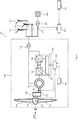
- Fig. 2 shows a total of a wind park 200, the electrical structure of the wind energy installation 100 being particularly emphasized.
- further wind energy installations 201, 202, 203 can be seen, all of which are part of wind farm 200.
- the wind energy installations of the wind farm 200 are connected to a three-phase electrical transmission network 230 via a transfer station 220 and can feed power into this.
- the wind turbines are each via a medium voltage transformer 128, which is shown in Fig. 2 is shown by way of example for the wind energy installation 100, connected to the transfer station 220 and the electrical transmission network 230.
- the rotor 130 of the wind energy installation 100 absorbs a torque from the wind and passes it on via a drive train 121, which includes a gearbox 122, to the rotor of a double-fed asynchronous generator 123, which is set up to convert the kinetic energy absorbed from the wind into electrical energy to convert and feed into the electrical transmission network 230.
- the stator of the generator 123 is connected to the electrical supply network 230 via a three-phase line.
- the rotor of the generator 123 is connected to an AC converter 124 via a three-phase line.
- the AC converter 124 is connected on the network side to the stator of the generator 123 and the electrical supply network 230 via a three-phase line.
- electrical lines are shown in the Fig. 2 shown schematically single-phase.
- the AC converter 124 has a rotor-side converter 125 and a line-side converter 126.
- a DC link is provided between the converters.
- a converter regulator 127 of the AC converter 124 is set up to set a generator torque and thus the power fed in via the stator circuit by regulating the rotor currents in the rotor of the generator 123.
- the converter controller 127 of the AC converter 124 is also set up to set the power fed in via the network-side converter 126.
- the converter controller 127 can specify manipulated variables for currents, voltages, powers and / or the generator torque to the rotor-side and / or the line-side converter 125, 126. Reactive and / or effective variables can be specified for the currents and powers.
- the rotor-side converter 125 sets the rotor currents and thus the generator torque by switching power electronic components.
- the converter controller 127 communicates with a wind turbine controller 129 and receives from the latter in particular a setpoint value for a generator torque or an active power to be output.
- the converter controller 127 provides measured values for currents present on the rotor and mains side and other measured variables to the wind turbine controller 129, which can be used by the latter to determine an available reactive power, that is to say the reactive power that can be provided by the wind turbine.
- the wind energy installation 100 has a speed sensor 161. This can be provided at a point on the drive train 121 that allows the speed of the drive train to be measured, for example on a transmission output shaft that is connected to the rotor of the generator 123.
- Speed values measured by the speed sensor 161 are available as input variables at the wind power plant controller 129.
- variables are present at the wind turbine controller 129, which are detected by means of the sensors of the sensor array 160.
- the wind speed and the wind direction are available as input variables on the wind turbine controller 129.
- Further measured variables such as, for example, the network frequency or the network voltage, are also available as input variables to the wind power installation controller 129 and are taken into account by it when the installation is controlled. These variables can also be taken into account when determining the available reactive power.
- the nacelle 120 of the wind power plant and thus its rotor 130 can be aligned with respect to the wind direction via an azimuth displacement device (not shown).
- the wind power plant controller 129 is also connected to a rotor blade angle adjusting device 151, by means of which the wind power plant controller 129 controls the pitch angles of the rotor blades 150.
- the wind energy installation controller 129 generally serves to regulate the operation of the wind energy installation 100.
- the wind power plant controller 129 can be designed, for example, as a programmable logic controller (PLC) and have software for regulating the wind power plant.
- PLC programmable logic controller
- the wind turbine controller 129 receives signals and control commands from a wind farm controller 210, with which it communicates via a data line.
- the wind farm controller 210 receives signals from the wind turbine controller 129 which serve as input variables for regulating the wind farm, for example information about the active and reactive power currently fed in and information about the available active and reactive power.
- the wind farm controller 210 is set up as a higher-level control unit to at least partially execute at least one of the methods according to the invention.
- the wind farm controller 210 sends signals for regulating the wind farm 200 to the individual wind energy installations 100, 201, 202, 203 or their wind energy installation controllers.
- the wind farm controller 210 can be designed, for example, as a programmable logic controller (PLC) and have software for regulating the wind farm.
- PLC programmable logic controller
- the wind farm controller 210 is connected via a data line to an external control device 211, for example a network control center, and receives from this setpoint specifications for the power to be fed in from the wind farm or the power factor to be set for this power.
- the wind farm controller 210 is set up to adjust the power output of the wind farm as a function of the setpoint values specified by the external control device 211.
- These target value specifications can for example be sent to the external from the wind farm controller 210 on the basis of an Control device 211 reported available power (active power, reactive power, apparent power) of the wind farm and the power requirement of the energy supply network can be specified.
- the power setpoint specification for the wind farm can be carried out by the wind farm controller 210 on the basis of measured values that are recorded by a sensor unit 221 at or near the network connection point of the wind farm and that are present as input variables at the wind farm controller 210.
- the target value specification can be specified based on a measured network frequency, the network voltage and / or the reactive power fed in.
- a corresponding regulation rule is stored in the wind farm controller 210.
- Corresponding methods are known from the prior art.
- measured values for the current output from the wind farm is active power P and reactive power Q is present at the wind farm controller 210th
- a setpoint value for the power factor PF should be specified for the power to be fed in to the wind farm controller 210.
- measured values or input values are understood to mean not only actual measured values, but in particular also those variables that have been calculated from the measured values or combinations of different values. Variables can also be determined as time averages over a suitable period.
- a flow chart can be seen which represents the sequence of one of the methods according to the invention.
- a specified power factor setpoint value PF soll is converted into a reactive power setpoint value Q soll .
- a current active power P ist is used for this, as shown by an arrow.
- the calculated Reactive power setpoint Q soll at reference numeral 320 is regulated to a regulated reactive power setpoint Q soll, reg by means of a current reactive power Q ist.
- This regulated reactive power setpoint value Q soll, reg is then distributed as a control variable to all wind energy installations participating in the method, as can be seen at reference numeral 330.
- the summation takes place over n in each case.
- Other distribution methods can also be combined with the method according to the invention. The method, which is carried out by the wind farm controller 210, can thus already end after this refinement.
- FIG. 3b a flow chart can be seen which shows the sequence of a further method according to the invention.
- the regulated reactive power setpoint Q setpoint , reg - instead of being used directly for the wind energy installations as a control variable - is first converted in step 340 into a set power factor setpoint value PF setpoint , reg .
- PF soll cos (arctan Q soll / P ist ) can be used for this.
- this regulated power factor setpoint value PF setpoint, reg can be specified to the wind energy installations as a control variable according to step 330.
- the established regulated power factor setpoint value PF setpoint, reg can be specified as a setpoint value for all wind energy installations participating in the method.
- the reactive power emitted by the systems is then fed in by the systems depending on the specified power factor and a specified target value for the active power to be delivered.
- FIG. 3c a flow chart can be seen which shows the sequence of a further method according to the invention.
- the regulated power factor setpoint value PF setpoint reg - instead of being specified directly to the wind energy installations as a control variable - is initially acted upon with offsets in step 350 for each of the wind energy installations participating in the method.
- a number of power factor setpoint values PF setpoint, disturbance, n thus arise, which are then specified as default values / control variables for the individual n wind power plants participating in the method in accordance with step 330.
- at least some of the systems can thus receive different power factor setpoints PF soll, stör, n.
- the offsets are randomly specified so that they add up to 0.
- the offsets are specified in such a way that they do not exceed a certain value in each case.
- the value can be based, for example, on the level of the power factor, so that the distribution only contains values that are small compared to the power factor and, for example, amount to a maximum of 20% of the power factor.
- the power factor setpoint can be used over the entire Wind farm can be adhered to better, since due to the control-related discretization occurring control oscillations are minimized, as explained above.
- the distributed offsets are preferably zero, so that the actual power output of the wind farm does not deviate from the specification.
Landscapes
- Engineering & Computer Science (AREA)
- Power Engineering (AREA)
- Supply And Distribution Of Alternating Current (AREA)
Abstract
Die Erfindung betrifft ein Verfahren zur Regelung der Leistungsabgabe eines Windparks mit mehreren Windenergieanlagen, mit den Schritten: Festlegen eines Leistungsfaktorsollwerts, Umrechnen des Leistungsfaktorsollwerts in einen Blindleistungssollwert mittels einer aktuellen Wirkleistung, Regeln des Blindleistungssollwerts mittels einer aktuellen Blindleistung auf einen eingeregelten Blindleistungssollwert.The invention relates to a method for regulating the power output of a wind farm with several wind turbines, with the following steps: setting a power factor nominal value, converting the power factor nominal value into a reactive power nominal value by means of a current active power, regulating the reactive power nominal value by means of a current reactive power to a regulated reactive power nominal value.
Description
Die Erfindung betrifft Verfahren zur Regelung der Leistungsabgabe eines Windparks, ein Steuerungssystem zur Ausführung der Verfahren sowie einen Windpark mit einem solchen Steuerungssystem.The invention relates to a method for regulating the power output of a wind farm, a control system for carrying out the method, and a wind farm with such a control system.
Im Stand der Technik sind verschiedene Verfahren zur Regelung der durch einen Windpark in ein Energieverteilungsnetz abgegebenen Leistung bekannt. Hierzu wird durch eine Steuereinheit eine leistungsbezogene elektrische Größe als Sollwert für den Windpark bzw. die einzelnen Windenergieanlagen des Windparks vorgegeben. Die Leistungsabgabe des Windparks kann somit eingestellt, insbesondere gedrosselt werden. Dies kann sinnvoll sein, wenn aufgrund bestimmter Umstände nicht die gesamte zur Verfügung stehende Leistung in das elektrische Netz eingespeist werden soll.Various methods for regulating the power output by a wind farm into an energy distribution network are known in the prior art. For this purpose, a power-related electrical variable is specified by a control unit as a setpoint value for the wind park or the individual wind energy installations of the wind park. The power output of the wind farm can thus be adjusted, in particular throttled. This can be useful if, due to certain circumstances, not all of the available power is to be fed into the electrical network.
Als leistungsbezogene elektrische Größen sind für den Windpark bzw. eine Windenergieanlage die Scheinleistung (S), die Wirkleistung (P) und die Blindleistung (Q) von Relevanz, wobei die Summe der Quadrate der Wirkleistung und der Blindleistung gleich dem Quadrat der Scheinleistung ist, S2 = P2 + Q2. Als geometrische Beziehung zwischen der Blindleistung und der Wirkleistung ist ein Phasenverschiebungswinkel ϕ = arctan (Q/P) definiert. Bei bekannten Verfahren zur Regelung der Leistungsabgabe eines Windparks wird als leistungsbezogene elektrische Größe zumeist der sogenannte Leistungsfaktor eingestellt und eingeregelt, wobei der Leistungsfaktor PF definiert ist als der Kosinus der Phasenverschiebung, PF = cos(ϕ). Ein solches Verfahren ist beispielsweise aus
Eine direkte Regelung des Leistungsfaktors ist jedoch relativ träge, insbesondere im Bereich um den Wert cos(ϕ) = 1. In diesem Bereich kann es zu einer Einregelzeit von ca. 5 Sekunden kommen, was die kurzfristige Regelbarkeit der Leistungsabgabe des Windparks einschränkt.However, direct control of the power factor is relatively sluggish, especially in the area around the value cos (ϕ) = 1. In this area, there can be a settling time of approx. 5 seconds, which limits the short-term controllability of the power output of the wind farm.
Der Erfindung liegt daher die Aufgabe zugrunde, die Leistungsabgabe eines Windparks bzw. einer Windenergieanlage mit einer möglichst kurzen Reaktionszeit zu regeln, insbesondere um schnell auf Änderungen im Netz reagieren zu können.The invention is therefore based on the object of regulating the power output of a wind park or a wind energy installation with the shortest possible response time, in particular in order to be able to react quickly to changes in the network.
Die Erfindung löst die Aufgabe durch ein Verfahren gemäß Anspruch 1. Vorteilhafte Ausgestaltungen sind Gegenstand der Unteransprüche, der Beschreibung sowie der Figuren.The invention achieves the object by a method according to claim 1. Advantageous configurations are the subject matter of the subclaims, the description and the figures.
Ein erfindungsgemäßes Verfahren zur Regelung der Leistungsabgabe eines Windparks mit mehreren Windenergieanlagen sieht die Schritte vor:
- Festlegen eines Leistungsfaktorsollwerts PFsoll,
- Umrechnen des Leistungsfaktorsollwerts PFsoll in einen Blindleistungssollwert Qsoll mittels einer aktuellen Wirkleistung Pist,
- Regeln des Blindleistungssollwerts Qsoll mittels einer aktuellen Blindleistung Qist auf einen eingeregelten Blindleistungssollwert Qsoll,reg.
- Defining a power factor setpoint PF should ,
- Converting the power factor reference value to PF into a reactive power reference value Q to a current by means of active power P,
- Regulating the reactive power setpoint Q soll by means of a current reactive power Q ist to a regulated reactive power setpoint Q soll, reg .
Nach diesem ersten erfindungsgemäßen Regelungsverfahren wird zunächst auch, wie bei dem eingangs erläuterten bekannten Verfahren, von einem Leistungsfaktorsollwert PFsoll ausgegangen. Dieser Leistungsfaktorsollwert PFsoll kann für alle Windenergieanlagen des Windparks derselbe sein. Im Gegensatz zu dem bekannten Regelverfahren wird jedoch nicht dieser Leistungsfaktorsollwert PFsoll unmittelbar an die an dem Verfahren teilnehmenden Windenergieanlagen vorgegeben. Stattdessen wird der Leistungsfaktorsollwert PFsoll zunächst anhand der aktuellen Wirkleistung Pist, also der Leistung die der Windpark aktuell einspeist, umgerechnet in einen Blindleistungssollwert Qsoll. Diese Umrechnung erfolgt dabei insbesondere über die eingangs erläuterte Relation zwischen Blindleistung und Wirkleistung. So kann sich der Blindleistungssollwert ergeben als Qsoll = Pist · tan (arccos PF). Anschließend wird erfindungsgemäß dieser Blindleistungssollwert Qsoll geregelt. Im Gegensatz zum Stand der Technik wird der Leistungsfaktor also nicht unmittelbar geregelt, sondern stattdessen die aus dem Leistungsfaktor ermittelte Blindleistung.According to this first control method according to the invention, as in the case of the known method explained at the beginning, a power factor setpoint value PF should be assumed. This target power factor value PF should be the same for all wind energy installations in the wind park. In contrast to the known control method, however, this power factor setpoint value PF should not be specified directly to the wind energy installations participating in the method. Instead, the target power factor value PF is initially based on the current active power P is , i.e. the power that the wind farm is currently feeding in, converted into a reactive power setpoint Q setpoint . This conversion takes place in particular via the relationship between reactive power and active power explained at the beginning. The reactive power setpoint can result as Q soll = P ist · tan (arccos PF). This reactive power setpoint Q setpoint is then regulated according to the invention. In contrast to the prior art, the power factor is not regulated directly, but instead the reactive power determined from the power factor.
Wie eingangs erläutert, ist eine direkte Regelung des Leistungsfaktors relativ träge. Insbesondere im Bereich um den Wert cos(ϕ) = 1 kommt es zu unvorteilhaft langen Regelzeiten aufgrund von Nichtlinearitäten. Wenn der Leistungsfaktor gegen 1 geht, also cos(ϕ) → 1, nähert sich die Wirkleistung der Scheinleistung an, also P → S. Damit verschwindet die Blindleistung, also Q → 0. Wie die Erfinder festgestellt haben, lässt sich der Blindleistungssollwert vor allem im Bereich von 0 wesentlich schneller regeln als der Leistungsfaktor im Bereich von 1. Somit erlaubt das erfindungsgemäße Verfahren eine schnelle Steuerung bzw. Regelung der Leistungsabgabe und bietet somit die Möglichkeit auf Änderungen im Netz mit geringer Reaktionszeit reagieren zu können.As explained at the beginning, direct control of the power factor is relatively sluggish. Particularly in the area around the value cos (ϕ) = 1 there are disadvantageously long control times due to non-linearities. When the power factor approaches 1, i.e. cos (ϕ) → 1, the real power approaches the apparent power, i.e. P → S. This means that the reactive power disappears, i.e. Q → 0. As the inventors have established, the reactive power setpoint can be above all regulate much faster in the range of 0 than the power factor in the range of 1. Thus, the method according to the invention allows a fast control or regulation of the power output and thus offers the possibility of being able to react to changes in the network with a short reaction time.
Entsprechend wird nach einer Ausgestaltung der eingeregelte Blindleistungssollwert Qsoll,reg an die Windenergieanlagen vorgegeben. Es kann somit der Blindleistungssollwert Qsoll,reg als leistungsbezogene elektrische Größe zur Steuerung der Leistungsabgabe des Windparks an die einzelnen Windenergieanlagen als Steuergröße vorgegeben werden. Insbesondere kann der Blindleistungssollwert anteilig an alle an dem Verfahren teilnehmenden Anlagen vorgegeben werden, wobei der anteilige Sollwert von der verfügbaren Blindleistung der jeweiligen Windenergieanlage abhängt.Correspondingly, according to one embodiment, the regulated reactive power setpoint value Q soll, reg is specified for the wind energy installations. The reactive power setpoint Q soll, reg can thus be specified as a power-related electrical variable for controlling the power output of the wind farm to the individual wind energy installations as a control variable. In particular, the reactive power setpoint value can be specified proportionally to all systems participating in the method, the proportionate setpoint value depending on the available reactive power of the respective wind energy system.
Auch kann jedoch nach einer Ausgestaltung der eingeregelte Blindleistungssollwert Qsoll,reg anhand der aktuellen Wirkleistung Pist zunächst in einen eingeregelten Leistungsfaktorsollwert PFsoll,reg umgerechnet und anschließend dieser eingeregelte Leistungsfaktorsollwert PFsoll,reg an die an dem Verfahren teilnehmenden Windenergieanlagen als Steuergröße vorgegeben werden. Nach dieser Ausgestaltung wird also nicht ein Blindleistungssollwert selbst vorgegeben sondern stattdessen ein aus diesem Blindleistungssollwert ermittelter Leistungsfaktorsollwert. In dieser Ausgestaltung wird insbesondere derselbe Leistungsfaktorsollwert an alle Windenergieanlagen übermittelt. Über das Regelverfahren eingeregelt wird dabei weiterhin die Blindleistung und nicht der Leistungsfaktor. Somit kann trotz der Vorgabe eines Leistungsfaktorsollwerts mit Vorteil die erfindungsgemäße schnelle Regelung erreicht werden. [HA1]However, may according to an embodiment of the turned regulated reactive power reference value Q should reg using the current active power P is initially in a the adjusted power factor set value PF should reg converted and then this be regulated power factor set value PF should reg be preset to participating in the procedure wind turbines as a control variable. According to this embodiment, a reactive power target value itself is not specified, but instead a power factor target value determined from this reactive power target value. In this embodiment, in particular, the same power factor setpoint is transmitted to all wind energy installations. The reactive power and not the power factor is still regulated via the control process. Thus, despite the specification of a power factor setpoint, the fast regulation according to the invention can advantageously be achieved. [HA1]
Nach einer diesbezüglichen Ausgestaltung wird der eingeregelte Leistungsfaktorsollwert PFsoll,reg für jede der am Verfahren teilnehmenden Windenergieanlagen mit jeweils einem Offset beaufschlagt und es werden anschließend die jeweiligen mit den Offsets beaufschlagten eingeregelten Leistungsfaktorsollwerte PFsoll,stör, n an die Windenergieanlagen als Steuergrößen vorgegeben. Auch können nach einer Ausgestaltung die eingeregelten Blindleistungssollwerte Qsoll,reg für jede der am Verfahren teilnehmenden Windenergieanlagen mit jeweils einem Offset beaufschlagt und anschließend diese jeweiligen mit Offsets beaufschlagten eingeregelten Blindleistungssollwerte Qsoll,stör, n an die Windenergieanlagen vorgegeben werden. Gemäß diesen Ausgestaltungen werden die jeweiligen Steuergrößen, also entweder der erläuterte eingeregelte Blindleistungssollwert oder der erläuterte eingeregelte Leistungsfaktorsollwert, vor der tatsächlichen Vorgabe als Steuergrößen an die Anlagen mit Offsets versehen. Das Beaufschlagen mit Offsets bedeutet dabei, dass die jeweiligen Steuergrößen künstlich in einem gewissen Maße variiert werden. Insbesondere können die Steuergrößen etwas erhöht oder verringert werden. Wurde mittels der erläuterten Verfahrensschritte eine Steuergröße für die Windenergieanlagen ermittelt, werden durch das Aufschlagen des Offsets nun einzelne Steuergrößen für jede der einzelnen Anlagen erzeugt. Wie die Erfinder festgestellt haben, tragen auch um solche Offsets veränderte Steuergrößen für die einzelnen am Verfahren teilnehmenden Windenergieanlagen zu einer Verringerung der Einregelzeit bei. Zudem kann mit so einem Offset die Steuergröße über den gesamten Windpark besser eingehalten werden, insbesondere bei einer Steuerung mit geringer Auflösung. Häufig verfügen die Anlagensteuerungen der Windenergieanlagen, insbesondere die Umrichterschnittstellen, über eine Auflösung von nur 16 Bit. Wird nun die erfindungsgemäß ermittelte Steuergröße den Anlagensteuerungen übermittelt, erfolgt eine Diskretisierung auf beispielsweise auf INT16. Ergibt sich nun eine Steuergröße nahe cos(cp) = 1, so führt aufgrund der Diskretisierung eine kleine Änderung der Steuergröße zu großen tatsächlichen Leistungsabgaben durch die Anlagen. Wird diese Steuergröße an alle Windenergieanlagen im Windpark verteilt, so ergibt sich eine entsprechend skalierte große Blindleistungs- bzw. Leistungsfaktoränderung. Dies kann bei ungünstigen Konstellationen, z.B. bei wenig Wirkleistung, zu Schwingungen führen. Um diese zu minimieren wird daher die Steuergröße nach der erläuterten Ausgestaltung für die einzelnen Windenergieanlagen durch einen Offset so verstellt, dass es im Mittel bei der vorgegebenen Steuergröße bleibt.According to a related embodiment, the regulated power factor setpoint PF soll, reg is applied with an offset for each of the wind turbines participating in the method, and the respective regulated power factor setpoints PF soll, disturb, n applied to the offsets are then specified to the wind turbines as control variables. According to one embodiment, the regulated reactive power setpoints Q soll, reg for each of the wind turbines participating in the method can each have an offset applied to them and then these respective regulated reactive power setpoints Q soll, disturb, n to which offsets are applied can be specified to the wind turbines. According to these refinements, the respective control variables, that is to say either the explained regulated reactive power setpoint value or the explained regulated power factor setpoint value, are provided with offsets as control variables to the systems before the actual specification. The application of offsets means that the respective control variables are artificially varied to a certain extent. In particular, the control variables can be increased or decreased somewhat. Has been a control variable for the wind power plants is determined by means of the explained method steps, individual control parameters are now generated for each of the individual plants by adding the offset. As the inventors have established, control variables changed by such offsets also contribute to a reduction in the settling time for the individual wind energy installations participating in the method. In addition, with such an offset, the control variable can be adhered to better over the entire wind farm, especially in the case of a control with low resolution. The system controls of the wind energy systems, in particular the converter interfaces, often have a resolution of only 16 bits. If the control variable determined according to the invention is now transmitted to the system controls, a discretization takes place on, for example, INT16. If the result is a control variable close to cos (cp) = 1, then, due to the discretization, a small change in the control variable leads to large actual output by the systems. If this control variable is distributed to all wind turbines in the wind farm, a correspondingly scaled large change in reactive power or power factor results. In the case of unfavorable constellations, for example with little real power, this can lead to oscillations. In order to minimize this, the control variable according to the embodiment explained for the individual wind energy installations is adjusted by an offset in such a way that, on average, it remains at the specified control variable.
Die Offsets können dabei grundsätzlich zufällig verteilt sein. Nach einer besonders bevorzugten Ausgestaltung erfolgt die Beaufschlagung mit den Offsets nach einer vorbestimmten, insbesondere zufälligen, Verteilung so, dass der Mittelwert über alle Offsets null ergibt. Über alle Anlagen ergibt sich damit im Mittel keine Abweichung. Die Offsets tragen damit zur Regelung bei ohne die zu erreichende Leistungsabgabe negativ zu beeinflussen. Alternativ oder zusätzlich sind die Offsets nach einer Ausgestaltung abhängig von Betriebsbedingungen der einzelnen Windenergieanlagen, insbesondere von die Blindleistung beeinflussenden Betriebsbedingungen. Derartige Betriebsbedingungen können beispielsweise die Temperatur des Umrichters oder des Generators sein.The offsets can in principle be randomly distributed. According to a particularly preferred embodiment, the offsets are applied according to a predetermined, in particular random, distribution such that the mean value over all offsets results in zero. There is therefore no deviation on average across all systems. The offsets thus contribute to the regulation without negatively influencing the power output to be achieved. Alternatively or additionally, according to one embodiment, the offsets are dependent on the operating conditions of the individual wind energy installations, in particular on those influencing the reactive power Operating conditions. Such operating conditions can be, for example, the temperature of the converter or the generator.
Nach einer Ausgestaltung wird zum Regeln des Blindleistungssollwerts Qsoll auf den eingeregelten Blindleistungssollwert Qsoll,reg eine Abweichung zwischen dem Blindleistungssollwert Qsoll und der aktuellen Blindleistung Q ermittelt wird und der eingeregelte Blindleistungssollwert Qsoll,reg derart festgelegt wird, dass die Abweichung verschwindet. Durch diese Regelungsmethode kann somit der eingeregelte Blindleistungssollwert Qsoll,reg erzeugt werden. Entsprechende Verfahren sind im Stand der Technik bekannt und werden hier nicht weiter erläutert.
[HA2]
Die erläuterten Schritte der erfindungsgemäßen Steuerverfahren können teilweise oder vollständig durch eine zentrale Steuerung des Windparks durchgeführt werden. Diese zentrale Steuerung kann die ermittelten Steuergrößen anschließend an die einzelnen am Verfahren teilnehmenden Windenergieanlagen übermitteln, insbesondere an die jeweiligen Anlagensteuerungen. Auch können jedoch die Anlagensteuerungen der einzelnen Windenergieanlagen dazu ausgebildet sein, die erläuterten Schritte des erfindungsgemäßen Steuerverfahrens jeweils selbst teilweise oder vollständig auszuführen. Es kann somit eine dezentrale Steuerung realisiert sein. Auch können einige Schritte durch die zentrale Steuerung und einige Schritte durch die Anlagensteuerungen lokal an den Anlagen durchgeführt werden. Insbesondere können die Anlagensteuerungen der einzelnen Windenergieanlagen eingerichtet sein, einen Wert für die verfügbare Blindleistung der jeweiligen Anlage zu ermitteln und an die zentrale Steuerung des Windparks zu übermitteln. Die verfügbare Blindleistung kann abhängig sein vom Betriebspunkt der Windenergieanlage und wird insbesondere begrenzt durch den Scheinstrom, den die Anlage in diesem Betriebspunkt bereitstellen kann. Entsprechende Verfahren zum Ermitteln der verfügbaren Blindleistung sind im Stand der Technik bekannt und werden hier nicht weiter erläutert.According to one embodiment, to regulate the reactive power target value Q soll on the regulated reactive power target value Q soll, reg a deviation between the reactive power target value Q soll and the current reactive power Q is determined and the regulated reactive power target value Q soll, reg is determined in such a way that the deviation disappears. The regulated reactive power setpoint Q setpoint , reg can thus be generated by this control method. Corresponding methods are known in the prior art and are not explained further here.
[HA2]
The explained steps of the control method according to the invention can be carried out partially or completely by a central control of the wind farm. This central control can then transmit the determined control variables to the individual wind power plants participating in the method, in particular to the respective plant controls. However, the system controls of the individual wind energy systems can also be designed to carry out the explained steps of the control method according to the invention in each case in part or in full. A decentralized control can thus be implemented. Some steps can also be carried out by the central control and some steps by the system controls locally on the systems. In particular, the system controls of the individual wind energy systems can be set up to determine a value for the available reactive power of the respective system and to transmit it to the central control of the wind park. The available reactive power can be dependent on the operating point of the wind energy installation and is in particular limited by the apparent current that the installation can provide at this operating point. Corresponding methods for determining the available reactive power are known in the prior art and are not explained further here.
Eine Ausgestaltung der Erfindung wird im Folgenden anhand von Figuren erläutert. Es zeigen schematisch:
- Figur 1
- eine Windenergieanlage in seitlicher Ansicht,
- Figur 2
- eine schematisches Diagramm der Windenergieanlage aus
Fig. 1 , und - Figuren 3a-3c
- Ablaufschemata der erfindungsgemäßen Regelungsverfahren.
- Figure 1
- a wind turbine in a side view,
- Figure 2
- a schematic diagram of the wind turbine
Fig. 1 , and - Figures 3a-3c
- Flow diagrams of the control method according to the invention.
Soweit nichts anderes angegeben ist, bezeichnen im Folgenden gleiche Bezugszeichen gleiche Gegenstände.Unless stated otherwise, the same reference symbols denote the same items in the following.
In
Der Rotor 130 der Windenergieanlage 100 nimmt ein Drehmoment aus dem Wind auf und leitet dieses über einen Antriebsstrang 121, der ein Getriebe 122 umfasst, an den Rotor eines doppeltgespeisten Asynchrongenerators 123 weiter, welcher eingerichtet ist, die aus dem Wind aufgenommene kinetische Energie in elektrische Energie umzuwandeln und in das elektrische Übertragungsnetz 230 einzuspeisen. Der Stator des Generators 123 ist über eine dreiphasige Leitung mit dem elektrischen Versorgungsnetz 230 verbunden. Der Rotor des Generators 123 ist über eine dreiphasige Leitung mit einem Wechselstrom-Umrichter 124 verbunden. Der Wechselstrom-Umrichter 124 ist netzseitig über eine dreiphasige Leitung mit dem Stator des Generators 123 und dem elektrischen Versorgungsnetz 230 verbunden. Zur besseren Übersicht werden elektrische Leitungen in der
Der Wechselstrom-Umrichter 124 weist einen rotorseitigen Umrichter 125 und einen netzseitigen Umrichter 126 auf. Zwischen den Umrichtern ist ein Gleichstromzwischenkreis vorgesehen. Ein Umrichterregler 127 des Wechselstrom-Umrichters 124 ist dazu eingerichtet, über eine Regelung der Rotorströme in dem Rotor des Generators 123 ein Generatormoment und damit die über den Statorkreis eingespeiste Leistung einzustellen. Der Umrichterregler 127 des Wechselstrom-Umrichters 124 ist weiterhin dazu eingerichtet, die über den netzseitigen Umrichter 126 eingespeiste Leistung einzustellen. Hierzu kann der Umrichterregler 127 dem rotorseitigen und/oder dem netzseitigen Umrichter 125, 126 Stellgrößen, für Ströme, Spannungen, Leistungen und/oder das Generatormoment vorgeben. Für die Ströme und Leistungen können Blind- und/oder Wirkgrößen vorgegeben werden. Entsprechende Regelungsverfahren sind allgemein für doppelt-gespeiste Asynchronmaschinen bekannt. Der rotorseitige Umrichter 125 stellt die Rotorströme und damit das Generatormoment durch die Schaltung von leistungselektronischen Bauelementen ein. Zur Regelung des Generatormoments kommuniziert der Umrichterregler 127 mit einem Windenergieanlagenregler 129 und erhält von diesem insbesondere einen Sollwert für ein Generatormoment oder eine abzugebende Wirkleistung. Der Umrichterregler 127 stellt Messwerte für rotor- und netzseitig vorliegende Ströme und weitere Messgrößen an den Windenergieanlagenregler 129, die durch diesen für die Bestimmung einer verfügbaren Blindleistung, also der durch die Windenergieanlage bereitstellbaren Blindleistung, verwendet werden können.The
Die Windenergieanlage 100 weist einen Drehzahlsensor 161 auf. Dieser kann an einer Stelle an dem Antriebsstrang 121 vorgesehen sein, der eine Messung der Drehzahl des Antriebstrangs zulässt, beispielsweise an einer Getriebeausgangswelle, die mit dem Rotor des Generators 123 verbunden ist. Von dem Drehzahlsensor 161 gemessene Drehzahlwerte liegen als Eingangsgröße an dem Windenergieanlagenregler 129 an. Weiterhin liegen an dem Windenergieanlagenregler 129 Größen an, die mittels der Sensoren des Sensorarrays 160 erfasst werden. Beispielsweise liegen die Windgeschwindigkeit und die Windrichtung als Eingangsgrößen an dem Windenergieanlagenregler 129 an. Auch weitere Messgrößen, wie beispielsweise die Netzfrequenz oder die Netzspannung liegen als Eingangsgrößen an dem Windenergieanlagenregler 129 und werden durch diesen bei der Regelung der Anlage berücksichtigt. Ebenso können diese Größen bei der Ermittlung der verfügbaren Blindleistung berücksichtigt werden. Die Gondel 120 der Windenergieanlage und damit ihr Rotor 130 kann über eine Azimutverfahreinrichtung (nicht gezeigt) gegenüber der Windrichtung ausgerichtet werden.The
Der Windenergieanlagenregler 129 ist weiterhin mit einer Rotorblattwinkelstellvorrichtung 151 verbunden, mittels derer der Windenergieanlagenregler 129 die Pitchwinkel der Rotorblätter 150 steuert. Der Windenergieanlagenregler 129 dient generell dazu, die Windenergieanlage 100 in ihrem Betrieb zu regeln. Der Windenergieanlagenregler 129 kann beispielsweise als speicherprogrammierbare Steuerung (SPS) ausgebildet sein und eine Software zur Regelung der Windenergieanlage aufweisen. Beispielsweise empfängt der Windenergieanlagenregler 129 Signale und Steuerbefehle von einem Windparkregler 210, mit welchem er über eine Datenleitung kommuniziert. Der Windparkregler 210 erhält von dem Windenergieanlagenregler 129 Signale, die als Eingangsgrößen für die Regelung des Windparks dienen, beispielsweise Informationen über die aktuell eingespeiste Wirk- und Blindleistung sowie Informationen über die verfügbare Wirk- und Blindleistung.The wind
In dem vorliegenden Ausführungsbeispiel ist der Windparkregler 210 als übergeordnete Steuereinheit dazu eingerichtet, zumindest eines der erfindungsgemäßen Verfahren zumindest teilweise auszuführen. Der Windparkregler 210 sendet Signale für die Regelung des Windparks 200 an die einzelnen Windenergieanlagen 100, 201, 202, 203 bzw. deren Windenergieanlagenregler. Der Windparkregler 210 kann beispielsweise als speicherprogrammierbare Steuerung (SPS) ausgebildet sein und eine Software zur Regelung des Windparks aufweisen. Der Windparkregler 210 ist über eine Datenleitung mit einer externen Regelungseinrichtung 211, beispielsweise einer Netzleitstelle, verbunden und erhält von dieser Sollwertvorgaben für die von dem Windpark einzuspeisende Leistung bzw. den für diese Leistung einzustellenden Leistungsfaktor. Der Windparkregler 210 ist eingerichtet, die Leistungsabgabe des Windparks in Abhängigkeit von Sollwertvorgaben der von der externen Regelungseinrichtung 211 einzustellen. Diese Sollwertvorgaben können beispielsweise auf Basis einer von dem Windparkregler 210 an die externe Regelungseinrichtung 211 gemeldeten verfügbaren Leistung (Wirkleistung, Blindleistung, Scheinleistung) des Windparks und dem Leistungsbedarf des Energieversorgungsnetzes vorgegeben sein. Alternativ oder ergänzend dazu kann die Leistungssollwertvorgabe für den Windpark durch den Windparkregler 210 auf Basis von Messwerten erfolgen, die mittels einer Sensoreinheit 221 am oder in der Nähe des Netzverknüpfungspunktes des Windparks erfasst werden und die als Eingangsgrößen an dem Windparkregler 210 anliegen. Die Sollwertvorgabe kann basierend auf einer gemessenen Netzfrequenz, der Netzspannung und/oder der eingespeisten Blindleistung vorgegeben werden. Zur Regelung der von dem Windpark eingespeisten Leistung ist in dem Windparkregler 210 eine entsprechende Regelungsvorschrift hinterlegt. Entsprechende Verfahren sind aus dem Stand der Technik bekannt. Zur Ausführung der erfindungsgemäßen Verfahren liegen insbesondere Messwerte für die aktuell von dem Windpark abgegebene Wirkleistung Pist und Blindleistung Qist an dem Windparkregler 210 an. Dem Windparkregler 210 kann insbesondere ein Sollwert für den Leistungsfaktor PFsoll der einzuspeisenden Leistung vorgegeben sein.In the present exemplary embodiment, the
Unter gemessenen Werten oder Eingangswerten werden im Rahmen dieser Beschreibung nicht nur eigentliche Messwerte verstanden, sondern insbesondere auch solche Größen, die aus den gemessenen Werten oder Verknüpfungen von unterschiedlichen Werten berechnet wurden. Dabei können auch Größen als zeitliche Mittelwerte über einen geeigneten Zeitraum bestimmt werden.In the context of this description, measured values or input values are understood to mean not only actual measured values, but in particular also those variables that have been calculated from the measured values or combinations of different values. Variables can also be determined as time averages over a suitable period.
In
Wie eingangs erläutert, ist eine direkte Regelung des Leistungsfaktors relativ träge. Insbesondere im Bereich um den Wert cos(ϕ) = 1 kommt es zu unvorteilhaft langen Regelzeiten aufgrund von Nichtlinearitäten. Wenn der Leistungsfaktor gegen 1 geht, also cos(ϕ) → 1, nähert sich die Wirkleistung der Scheinleistung an, also P → S. Damit verschwindet die Blindleistung, also Q → 0. Der Blindleistungssollwert lässt sich vor allem im Bereich von 0 jedoch wesentlich schneller regeln als der Leistungsfaktor im Bereich von 1, wie die Erfinder festgestellt haben. Mit den erläuterten Verfahrensschritten kann somit bereits eine schnelle Steuerung der Leistungsabgabe erreicht werden.As explained at the beginning, direct control of the power factor is relatively sluggish. Particularly in the area around the value cos (ϕ) = 1 there are disadvantageously long control times due to non-linearities. When the power factor approaches 1, i.e. cos (ϕ) → 1, the real power approaches the apparent power, i.e. P → S. This means that the reactive power disappears, i.e. Q → 0. However, the reactive power setpoint can be significantly reduced, especially in the range of 0 regulate faster than the power factor in the range of 1, as the inventors have established. With the method steps explained, a quick control of the power output can thus already be achieved.
In
In
Dies trägt ebenfalls zur Verringerung der Regelzeit bei, insbesondere um cos(cp) = 1. Zudem kann mit so einem Offset der Leistungsfaktorsollwert über den gesamten Windpark besser eingehalten werden, da aufgrund der steuerungsbedingten Diskretisierung auftretende Regelschwingungen minimiert werden, wie oben erläutert. Im Mittel sind die verteilten Offsets dabei bevorzugt null, sodass die tatsächliche Leistungsabgabe des Windparks nicht von der Vorgabe abweicht.This also contributes to reducing the control time, in particular by cos (cp) = 1. In addition, with such an offset, the power factor setpoint can be used over the entire Wind farm can be adhered to better, since due to the control-related discretization occurring control oscillations are minimized, as explained above. On average, the distributed offsets are preferably zero, so that the actual power output of the wind farm does not deviate from the specification.
- 100100
- WindenergieanlageWind turbine
- 110110
- Turmtower
- 120120
- Gondelgondola
- 130130
- Rotorrotor
- 140140
- RotornabeRotor hub
- 150150
- RotorblattRotor blade
- 160160
- SensorarraySensor array
- 200200
- WindparkWind farm
- 201, 202, 203201, 202, 203
- WindenergieanlageWind turbine
- 210210
- zentraler Windparkreglercentral wind farm controller
- 211211
- externe Regelungseinrichtung (Netzbetreiber)external control device (network operator)
- 220220
- ÜbergabestationTransfer station
- 221221
- SensoreinheitSensor unit
- 230230
- elektrisches Übertragungsnetzelectrical transmission network
- 121121
- AntriebstrangPowertrain
- 122122
- Getriebetransmission
- 123123
- Generatorgenerator
- 124124
- UmrichterConverter
- 125125
- rotorseitiger Umrichterrotor-side converter
- 126126
- netzseitiger Umrichterline-side converter
- 127127
- UmrichterreglerConverter controller
- 128128
- MittelspannungstransformatorMedium voltage transformer
- 129129
- WindenergieanlagenreglerWind turbine controller
- 151151
- RotorblattwinkelstellvorrichtungRotor blade angle adjustment device
- 161161
- DrehzahlsensorSpeed sensor
- PFsollPFsoll
- LeistungsfaktorsollwertPower factor setpoint
- PistPist
- WirkleistungsistwertActive power actual value
- QistQist
- BlindleistungsistwertReactive power actual value
- QsollQsoll
- BlindleistungssollwertReactive power setpoint
- Qsoll,regQsoll, reg
- geregelter BlindleistungssollwertRegulated reactive power setpoint
- PFsoll,regPFsoll, reg
- geregelter Leistungsfaktorsollwertregulated power factor setpoint
- PFsoll,stör, nPFsoll, sturgeon, n
- geregelter, mit Störgröße beaufschlagter Leistungsfaktorsollwert für die Windenergieanlage nregulated power factor setpoint for the wind turbine n
- 310 - 350310-350
- VerfahrensschritteProcedural steps
Claims (12)
Priority Applications (1)
| Application Number | Priority Date | Filing Date | Title |
|---|---|---|---|
| EP20152238.0A EP3852211A1 (en) | 2020-01-16 | 2020-01-16 | Method for controlling the output of a wind farm |
Applications Claiming Priority (1)
| Application Number | Priority Date | Filing Date | Title |
|---|---|---|---|
| EP20152238.0A EP3852211A1 (en) | 2020-01-16 | 2020-01-16 | Method for controlling the output of a wind farm |
Publications (1)
| Publication Number | Publication Date |
|---|---|
| EP3852211A1 true EP3852211A1 (en) | 2021-07-21 |
Family
ID=69174416
Family Applications (1)
| Application Number | Title | Priority Date | Filing Date |
|---|---|---|---|
| EP20152238.0A Pending EP3852211A1 (en) | 2020-01-16 | 2020-01-16 | Method for controlling the output of a wind farm |
Country Status (1)
| Country | Link |
|---|---|
| EP (1) | EP3852211A1 (en) |
Citations (5)
| Publication number | Priority date | Publication date | Assignee | Title |
|---|---|---|---|---|
| EP1746285A2 (en) | 2005-07-20 | 2007-01-24 | General Electric Company | Method and apparatus for controlling windfarms and windfarms controlled thereby |
| US20100025994A1 (en) * | 2008-07-29 | 2010-02-04 | General Electric Company | Intra-area master reactive controller for tightly coupled windfarms |
| DE102009011053A1 (en) * | 2009-03-02 | 2010-09-16 | Btc Business Technology Consulting Ag | Wind farm regulator |
| US20130093186A1 (en) * | 2007-12-14 | 2013-04-18 | Shinji Arinaga | Wind-power generation system and operation control method therefor |
| US20160237990A1 (en) * | 2015-02-18 | 2016-08-18 | General Electric Company | Determining reactive power capability of a renewable energy system |
-
2020
- 2020-01-16 EP EP20152238.0A patent/EP3852211A1/en active Pending
Patent Citations (5)
| Publication number | Priority date | Publication date | Assignee | Title |
|---|---|---|---|---|
| EP1746285A2 (en) | 2005-07-20 | 2007-01-24 | General Electric Company | Method and apparatus for controlling windfarms and windfarms controlled thereby |
| US20130093186A1 (en) * | 2007-12-14 | 2013-04-18 | Shinji Arinaga | Wind-power generation system and operation control method therefor |
| US20100025994A1 (en) * | 2008-07-29 | 2010-02-04 | General Electric Company | Intra-area master reactive controller for tightly coupled windfarms |
| DE102009011053A1 (en) * | 2009-03-02 | 2010-09-16 | Btc Business Technology Consulting Ag | Wind farm regulator |
| US20160237990A1 (en) * | 2015-02-18 | 2016-08-18 | General Electric Company | Determining reactive power capability of a renewable energy system |
Similar Documents
| Publication | Publication Date | Title |
|---|---|---|
| EP2989708B1 (en) | Method for feeding electrical power into an electrical supply network | |
| EP2411669B1 (en) | Method for operating a wind turbine | |
| EP2093419B1 (en) | Method of controlling a wind turbine and wind turbine | |
| EP2841766B1 (en) | Wind farm with fast local reactive power control | |
| EP3408913B1 (en) | Method for feeding electrical power into an electric supply network | |
| EP2324551B1 (en) | Power control for a wind park | |
| EP1290343B1 (en) | Azimuth drive for wind energy plants | |
| EP3420222B1 (en) | Method and windfarm control module for controlling a windfarm | |
| EP2659137B1 (en) | Wind farm and method for operating a wind farm | |
| EP2244348A2 (en) | Wind farm with multiple wind energy assemblies and method for regulating the feed-in from a wind farm | |
| EP3095168B1 (en) | Method and control device for operating a wind power plant and/or park and wind power plant and wind park | |
| EP1892412A1 (en) | Method for operating wind farms | |
| DE102016007098A1 (en) | Wind farm with fast response to grid parameter changes and method for doing so | |
| DE102016120700A1 (en) | Method for operating a wind energy plant | |
| EP3496227A1 (en) | Wind farm with autonomous phase angle control | |
| EP3754178B1 (en) | Method for operating a wind farm | |
| EP2864631A2 (en) | Wind farm having a plurality of network feed-in points | |
| EP3495656B1 (en) | Method for determining the load dynamics of a wind power station | |
| EP3909107A1 (en) | Wind turbine | |
| EP3852211A1 (en) | Method for controlling the output of a wind farm | |
| EP3848575A1 (en) | Method for operating a wind farm with a plurality of wind turbines and corresponding wind farm | |
| EP3021448B1 (en) | Wind energy system and method for operating a wind energy system | |
| EP3887676A1 (en) | Method for operating a wind power plant | |
| EP3852214A1 (en) | Method for controlling a wind energy system | |
| WO2011085962A2 (en) | Method for reducing the complexity of wind turbines in the wind park network, and arrangement of a wind park |
Legal Events
| Date | Code | Title | Description |
|---|---|---|---|
| PUAI | Public reference made under article 153(3) epc to a published international application that has entered the european phase |
Free format text: ORIGINAL CODE: 0009012 |
|
| STAA | Information on the status of an ep patent application or granted ep patent |
Free format text: STATUS: THE APPLICATION HAS BEEN PUBLISHED |
|
| AK | Designated contracting states |
Kind code of ref document: A1 Designated state(s): AL AT BE BG CH CY CZ DE DK EE ES FI FR GB GR HR HU IE IS IT LI LT LU LV MC MK MT NL NO PL PT RO RS SE SI SK SM TR |
|
| STAA | Information on the status of an ep patent application or granted ep patent |
Free format text: STATUS: REQUEST FOR EXAMINATION WAS MADE |
|
| 17P | Request for examination filed |
Effective date: 20220119 |
|
| RBV | Designated contracting states (corrected) |
Designated state(s): AL AT BE BG CH CY CZ DE DK EE ES FI FR GB GR HR HU IE IS IT LI LT LU LV MC MK MT NL NO PL PT RO RS SE SI SK SM TR |
|
| STAA | Information on the status of an ep patent application or granted ep patent |
Free format text: STATUS: EXAMINATION IS IN PROGRESS |
|
| 17Q | First examination report despatched |
Effective date: 20240522 |