EP2221794A1 - Label sheet and label sheet producing device - Google Patents
Label sheet and label sheet producing device Download PDFInfo
- Publication number
- EP2221794A1 EP2221794A1 EP08711841A EP08711841A EP2221794A1 EP 2221794 A1 EP2221794 A1 EP 2221794A1 EP 08711841 A EP08711841 A EP 08711841A EP 08711841 A EP08711841 A EP 08711841A EP 2221794 A1 EP2221794 A1 EP 2221794A1
- Authority
- EP
- European Patent Office
- Prior art keywords
- label
- backing sheet
- unit
- folding
- sheet
- Prior art date
- Legal status (The legal status is an assumption and is not a legal conclusion. Google has not performed a legal analysis and makes no representation as to the accuracy of the status listed.)
- Granted
Links
Images




Classifications
-
- G—PHYSICS
- G09—EDUCATION; CRYPTOGRAPHY; DISPLAY; ADVERTISING; SEALS
- G09F—DISPLAYING; ADVERTISING; SIGNS; LABELS OR NAME-PLATES; SEALS
- G09F3/00—Labels, tag tickets, or similar identification or indication means; Seals; Postage or like stamps
- G09F3/08—Fastening or securing by means not forming part of the material of the label itself
- G09F3/10—Fastening or securing by means not forming part of the material of the label itself by an adhesive layer
-
- B—PERFORMING OPERATIONS; TRANSPORTING
- B31—MAKING ARTICLES OF PAPER, CARDBOARD OR MATERIAL WORKED IN A MANNER ANALOGOUS TO PAPER; WORKING PAPER, CARDBOARD OR MATERIAL WORKED IN A MANNER ANALOGOUS TO PAPER
- B31D—MAKING ARTICLES OF PAPER, CARDBOARD OR MATERIAL WORKED IN A MANNER ANALOGOUS TO PAPER, NOT PROVIDED FOR IN SUBCLASSES B31B OR B31C
- B31D1/00—Multiple-step processes for making flat articles ; Making flat articles
- B31D1/02—Multiple-step processes for making flat articles ; Making flat articles the articles being labels or tags
- B31D1/021—Making adhesive labels having a multilayered structure, e.g. provided on carrier webs
-
- B—PERFORMING OPERATIONS; TRANSPORTING
- B65—CONVEYING; PACKING; STORING; HANDLING THIN OR FILAMENTARY MATERIAL
- B65H—HANDLING THIN OR FILAMENTARY MATERIAL, e.g. SHEETS, WEBS, CABLES
- B65H29/00—Delivering or advancing articles from machines; Advancing articles to or into piles
- B65H29/24—Delivering or advancing articles from machines; Advancing articles to or into piles by air blast or suction apparatus
- B65H29/241—Suction devices
-
- B—PERFORMING OPERATIONS; TRANSPORTING
- B65—CONVEYING; PACKING; STORING; HANDLING THIN OR FILAMENTARY MATERIAL
- B65H—HANDLING THIN OR FILAMENTARY MATERIAL, e.g. SHEETS, WEBS, CABLES
- B65H37/00—Article or web delivery apparatus incorporating devices for performing specified auxiliary operations
- B65H37/06—Article or web delivery apparatus incorporating devices for performing specified auxiliary operations for folding
-
- B—PERFORMING OPERATIONS; TRANSPORTING
- B65—CONVEYING; PACKING; STORING; HANDLING THIN OR FILAMENTARY MATERIAL
- B65H—HANDLING THIN OR FILAMENTARY MATERIAL, e.g. SHEETS, WEBS, CABLES
- B65H39/00—Associating, collating, or gathering articles or webs
- B65H39/14—Associating sheets with webs
-
- G—PHYSICS
- G09—EDUCATION; CRYPTOGRAPHY; DISPLAY; ADVERTISING; SEALS
- G09F—DISPLAYING; ADVERTISING; SIGNS; LABELS OR NAME-PLATES; SEALS
- G09F3/00—Labels, tag tickets, or similar identification or indication means; Seals; Postage or like stamps
- G09F3/02—Forms or constructions
-
- B—PERFORMING OPERATIONS; TRANSPORTING
- B65—CONVEYING; PACKING; STORING; HANDLING THIN OR FILAMENTARY MATERIAL
- B65H—HANDLING THIN OR FILAMENTARY MATERIAL, e.g. SHEETS, WEBS, CABLES
- B65H2301/00—Handling processes for sheets or webs
- B65H2301/40—Type of handling process
- B65H2301/44—Moving, forwarding, guiding material
- B65H2301/447—Moving, forwarding, guiding material transferring material between transport devices
- B65H2301/4472—Suction grippers, e.g. moved in paths enclosing an area
- B65H2301/44724—Suction grippers, e.g. moved in paths enclosing an area reciprocated in rectilinear paths
-
- B—PERFORMING OPERATIONS; TRANSPORTING
- B65—CONVEYING; PACKING; STORING; HANDLING THIN OR FILAMENTARY MATERIAL
- B65H—HANDLING THIN OR FILAMENTARY MATERIAL, e.g. SHEETS, WEBS, CABLES
- B65H2701/00—Handled material; Storage means
- B65H2701/10—Handled articles or webs
- B65H2701/12—Surface aspects
- B65H2701/124—Patterns, marks, printed information
- B65H2701/1244—RFID [Radio Frequency Identification Data] transponder
-
- B—PERFORMING OPERATIONS; TRANSPORTING
- B65—CONVEYING; PACKING; STORING; HANDLING THIN OR FILAMENTARY MATERIAL
- B65H—HANDLING THIN OR FILAMENTARY MATERIAL, e.g. SHEETS, WEBS, CABLES
- B65H2701/00—Handled material; Storage means
- B65H2701/10—Handled articles or webs
- B65H2701/19—Specific article or web
- B65H2701/192—Labels
-
- B—PERFORMING OPERATIONS; TRANSPORTING
- B65—CONVEYING; PACKING; STORING; HANDLING THIN OR FILAMENTARY MATERIAL
- B65H—HANDLING THIN OR FILAMENTARY MATERIAL, e.g. SHEETS, WEBS, CABLES
- B65H2801/00—Application field
- B65H2801/75—Labelling machines
-
- Y—GENERAL TAGGING OF NEW TECHNOLOGICAL DEVELOPMENTS; GENERAL TAGGING OF CROSS-SECTIONAL TECHNOLOGIES SPANNING OVER SEVERAL SECTIONS OF THE IPC; TECHNICAL SUBJECTS COVERED BY FORMER USPC CROSS-REFERENCE ART COLLECTIONS [XRACs] AND DIGESTS
- Y10—TECHNICAL SUBJECTS COVERED BY FORMER USPC
- Y10T—TECHNICAL SUBJECTS COVERED BY FORMER US CLASSIFICATION
- Y10T428/00—Stock material or miscellaneous articles
- Y10T428/24—Structurally defined web or sheet [e.g., overall dimension, etc.]
- Y10T428/24628—Nonplanar uniform thickness material
Definitions
- the present invention relates to a label sheet consisting of labels which are applied to various sorts of articles and which are temporarily attached to a backing sheet in a detachable manner.
- the present invention relates to a label sheet and a label sheet manufacturing device for manufacturing this label sheet, more particularly, a label which can temporarily be attached to the backing sheet by protruding a portion of the label from the back surface side to the front surface side in a chevron shape, and which can be peeled off from the backing sheet and applied to the article by manual procedures.
- a label L with a portion 2 of the label L protruded by folding the label L from the back surface side to the front surface side in a chevron shape and attached to an article is conventionally known.
- This label L is in a rectangular shape, wherein a folded portion 1 is formed by folding and protruding an intermediate portion of the label from back surface side to front surface side in a chevron shape, having a first side surface 4 (one side surface 4) and a second side surface 5 (other side surface 5) with an apex portion 3 as a border therebetween, and has outer end portions 7 consecutively provided respectively from a base portion of the first side surface 4 and from a base portion of the second side surface 5 of the folded portion 1 via bent portions 6.
- This label L is provided with glue on its back surface.
- a plurality of labels, in planar state are provided in rows on a strip form backing sheet 8, in a form of planar label sheet 9.
- the strip form backing sheet 8 is consisting of a central backing sheet 8a, in the center, where the first side surface 4 and the second side surface 5 are temporarily attached, and a pair of end backing sheets 8b where the both outer end portions 7 are temporarily attached.
- the label sheet of the present invention proposes the following arrangements.
- a label sheet with a label temporarily attached to a backing sheet in a detachable manner wherein, a folded portion of the label is formed by folding and protruding an intermediate portion of the label from back surface side to front surface side in a chevron shape, having a first side surface and a second side surface with an apex portion as a border therebetween, and wherein outer end portions, consecutively provided respectively from a base portion of the first side surface and from a base portion of the second side surface of the folded portion via bent portions, are temporarily attached to the backing sheet with the folded portion in a protruding state.
- the label when attaching a label to an article, the label is peeled off from the backing sheet and then the outer end portions of the label are attached to the article as they are by manual procedures.
- the label is temporarily attached to the backing sheet with the folded portion in a protruding state.
- the attaching procedure of the label it is not required to perform the folding procedure one by one as in the past, but is only required to attach the outer end portions to the article as they are, such that the attaching procedure can be easily performed.
- the label sheet of the present invention is configured to provide: a label sheet manufacturing device manufacturing a label sheet with the label temporarily attached to a backing sheet in a detachable manner, wherein a folded portion of the label is formed by folding and protruding an intermediate portion of the label from back surface side to front surface side in a chevron shape, having a first side surface and a second side surface with an apex portion as a border therebetween, and wherein outer end portions, consecutively provided respectively from a base portion of the first side surface and from a base portion of the second side surface of the folded portion via bent portions, are temporarily attached to the backing sheet with the folded portion in a protruding state
- the label sheet manufacturing device comprising: a label supply unit which supplies planar label; a label holding unit which attracts and holds the label supplied from the label supply unit; a backing sheet conveyance unit which conveys the backing sheet; a folding and temporary attaching unit , wherein a folded portion of the label is formed by folding and protruding a portion of
- the label holding unit holds this label and the folding and temporary attaching unit forms the folded portion formed by folding and protruding a portion of the label from back surface side to front surface side in a chevron shape, having a first side surface and a second side surface with an apex portion as a border therebetween.
- the outer end portions consecutively provided respectively from the folded portion via the bent portions are temporarily attached to the backing sheet conveyed by the backing sheet conveyance unit. Therefore, it is possible to easily manufacture the label sheet with the label, of which the folded portion is temporarily attached to the backing sheet with the folded portion in a protruding state.
- the label When attaching a label manufactured in this manner to an article, as in the same way as above, the label is peeled off from the backing sheet and the outer end portions are attached to the article as they are by manual procedures.
- the label is formed with the apex portion and the bent portions of the label, folded in advance, forming the folded portion, and is temporarily attached to the backing sheet with the folded portion in a protruding state. Therefore, in the attaching procedure of the label, it is not required to perform the folding procedure one by one as in the past, but is only required to attach the outer end portions to the article as they are, such that the attaching procedure can be easily performed.
- the label sheet manufacturing device comprising the label holding unit configured to comprise a pair of divided bodies for attracting and holding the label, and the folding and temporary attaching unit configured to comprise a folding unit which, relatively approaches and separates the each divided bodies, and at approach of the divided bodies, forms the folded portion by pressing the bent portions of the label with the end surfaces of which each divided bodies are opposing and folding a part of the label, and a movement control unit which controls the movement of the divided bodies of the folding unit. Accordingly, when temporarily attaching a label to a backing sheet, a pair of divided bodies of the label holding unit attracts and holds the label, and the pair of divided bodies each approaching the other from the separated position by the folding and temporary attaching unit.
- the bent portions of the label are pressed by the end surfaces opposing each divided bodies, and the portion of the label is folded forming the folded portion. Then, in this state, the label is attached to the backing sheet. Because of this, the folding and temporary attaching procedure can be performed extremely easily by the folding and temporary attaching unit protruding a portion of the label in a chevron shape and automatically temporarily attaching the label to the backing sheet.
- the label sheet manufacturing device is provided with a movement control unit which controls the movement of the divided bodies of the folding unit, at separation of the divided bodies, the portion of the label corresponding to the folded portion may be positioned between the pair of divided bodies. Therefore, at approach, the outer end portions of the label are brought into contact with the divided bodies, thereby the portion of the label may be folded securely at the bent portions, securely performing label attachment.
- the movement control unit position the moving divided bodies at a contacting position where the divided bodies contact each other when the label supplied from the label supplying unit is attracted and held, to a separating position where the divided bodies separate from the other enabling folding of the label, and to a folded portion forming position where the divided bodies approximate/approach the other from the separating position forming the folded portion.
- Ac cording to the setting manner of the folded portion forming position it is possible to change the attaching manner of the label. For example, by attaching the label by forming a space between the first side surface and the second side surface of the label as it were in an inverted V-shape, or by attaching the label by joining the first side surface and the second side surface, etc.
- the label sheet manufacturing device comprising the backing sheet conveyance unit configured to comprise a backing sheet reel holding unit which holds the backing sheet reel with the strip form backing sheet wound around rotatably, and a strip form backing sheet conveyance mechanism which pulls out the strip form backing sheet from the backing sheet reel held by the backing sheet holding unit and conveys the strip form backing sheet. Accordingly, it is possible to sequentially temporarily attach the label to the strip form backing sheet with the folded portion in a protruded state, thereby improving the manufacturing efficiency.
- the label sheet manufacturing device is configured provided with a cutting mechanism, which cuts the strip form backing sheet with the label temporarily attached into a predetermined length. Accordingly, as the label sheet is manufactured with each one label or with each set of plurality of labels, it is possible to facilitate the handling.
- the folding and temporary attaching unit is comprised to configure a transferring unit which transfers the label holding unit to the two positions, the attracting and holding position where the label is attracted and held by the label holding unit, and the temporary attaching position where the attracted and held label is temporarily attached on the backing sheet.
- the folding and temporary attaching unit with a transferring unit which transfers the label holding unit to the two positions, the attracting and holding position where the label is attracted and held, and the temporary attaching position where the attracted and held label is temporarily attached to the strip form backing sheet; to set the temporary attaching position at a downstream side of the conveying direction of the strip form backing sheet with regard to the attracting and holding position; and the transferring unit to transfer the label holding unit from the attracting and holding position towards the temporary attaching position in an oblique direction.
- the label holding unit moves away from the label supplying unit. Therefore, compared to the case where the label holding unit transferred in a vertical direction, it is possible to reliably prevent the interference with the label supplying unit.
- the label when attaching a label to an article, it is possible to peel off the label from the backing sheet and attach the label on the article as they are by manual procedures.
- the label is formed with the apex portion and the bent portions of the label, folded in advance, forming the folded portion, and is temporarily attached to the backing sheet with the folded portion in a protruding state. Therefore, in the attaching procedure of the label, it is not required to perform the folding procedure one by one as in the past, but is only required to attach the outer end portions to the article as they are, such that the attaching procedure can be extremely easily performed and the work efficiency of attaching the label can be improved considerably.
- FIG. 1 , 4 and 6 shows the label sheet LS in the embodiment of the present invention.
- the label LS is formed with a label L temporarily attached to the backing sheet D.
- the label L in this embodiment is a rectangular shape, wherein a folded portion 1 is formed by folding and protruding a portion 2 in the middle of the label from back surface side to front surface side in a chevron shape, having a first side surface 4 and a second side surface 5 with an apex portion 3 as a border therebetween, and has outer end portions 7 consecutively provided respectively from a base portion of the first side surface 4 and from a base portion of the second side surface 5 of the folded portion 1 via bent portions 6.
- the label L is applied with an adhesive only on the back surface side surface of the outer end portions 7 or on the entire back surface side surface.
- the outer end portions 7 are temporarily attached to the backing sheet D with the folded portion 1 in a protruding state. That is, the label is temporarily attached to the backing sheet D in a state with the folded portion 1 folding and uprising in advance.
- an RFID (Radio Frequency Identification) tag T is provided on at least one of either the first side surface 4 or the second side surface 5 of the label L.
- the RFID tag T is comprised of an IC (Integrated Circuit) chip which stores all sorts of information, and an antenna for communication which is connected to the IC chip, and is prevailing in the recent years.
- the label L is not necessarily limited to the label L with an RFID tag T, but it can be a label L without a RFID tag T.
- at the folding lines P of the apex portion 3 and the bent portions 6, perforations may be formed.
- the label L of the label sheet LS of this embodiment is not necessarily in a rectangular shape, but it may be in various types of shape such as a label with an intermediate portion of the label in a variant form.
- the backing sheet D is a backing sheet formed by cutting the strip form backing sheet Da, for example, by each one label L or by each set of plurality of labels L accordingly.
- the backing sheet D is formed at a predetermined length such that some blank space is left, corresponding to each one label L.
- holes d are provided at the both end edge portions along the longitudinal direction of the strip form backing sheet Da, holes d, in which the later mentioned pins of the feed roller are inserted, are provided with predetermined interval.
- the label sheet manufacturing device is provided with a label supplying unit 10 which supplies the planar label L.
- the label L at first, is temporarily attached in a line onto the strip form base backing sheet Dd in a planar state as shown in Figs. 1 and 2 (a) .
- Th e label L is temporarily attached onto the strip form base backing sheet with the folding lines P (shown in Fig. 6 ) of the apex portion 3 and the bent portions 6 perpendicular to the longitudinal direction (the supplying direction R of the label L) of the strip form base backing sheet Dd.
- the label supplying unit 10 as shown in Figs.
- the reference number 12 is the reader/writer which rewrites the data on the IC chip of the RFID tag T and which performs the verification, etc. by writing and reading of information.
- the reference number 13 is the thermal head for printing on the label L and the reference number 14 is the platen.
- the label sheet manufacturing device is provided with a label holding unit 20 which attracts and holds the label L supplied from the label supplying unit 10.
- the label holding unit 20 is provided with an attracting and holding board 21.
- the attracting and holding board 21 attracts and hold the front surface side of the label L peeled off by the peel-off board 11.
- a plurality of small holes (not shown in the diagram) which attracts and holds the surface of the label L by air suction is provided.
- the attracting and holding board 21 is divided and formed by the line perpendicular to the supplying direction R of the label L, in other words, the line parallel to the folding lines P of the apex portion 3 and the bent portions 6 of the label L, and configured and provided with a pair of divided bodies 21 A and 21 B which attracts and holds the label L.
- the label sheet manufacturing device is provided with a folding and temporary attaching unit 30.
- the folding and temporary attaching unit 30 is provided with an air cylinder unit 22, as a transferring unit transferring the attracting and holding board 21 of the label holding unit 20, to the two positions; the attracting and holding position X (in Figs. 1 and 2 ) where the label attracting and holding board 21 of the label holding unit 20 attracts and holds the label L, and to the temporary attaching position Y (in Fig. 3(b) ) where the label L attracted and held at the folded portion forming position K by the divided bodies (a first divided body) 21 A and (a second divided body) 21 B are temporarily attached to the strip form backing sheet Da conveyed by the later mentioned backing sheet conveyance unit.
- the air cylinder unit 22 comprising of a cylinder 22a and a piston 22b
- the attracting and holding board 21 is transferred to the attracting and holding position X (in Figs. 1 and 2 ) at which the label L is attracted and held, and to the temporary attaching position Y (in Fig. 3(b) ) at which the label L is temporarily attached to the strip form backing sheet Da.
- the cylinder 22a of the air cylinder unit 22 is supported by a machine base 15, and a fixing board 23 supporting the attracting and holding board 21 is assembled at the end of the piston 22b.
- the temporary attaching position Y in relation to the attracting and holding position X, is configured at the downstream side of the conveyance direction R of the strip form backing sheet Da.
- the air cylinder unit 22 is supported by the machine base 15 so as to transfer the label holding unit 20 from the attracting and holding position X to the temporary attaching position Y in a oblique direction such that the advancing direction of the piston 22b is oblique.
- the air cylinder 22 transfers the label holding unit 20 from the attracting and holding position X towards the temporary attaching position Y in an oblique direction such that the label holding unit 20 moves away from the label supplying unit 10. Therefore, compared to the case where the label holding unit is transferred in a vertical direction, it is possible to reliably prevent the interference with the label supplying unit 10.
- an air blowing pipe 24 which assists attracting and holding of the label L by the attracting and holding board 21 at the attracting and holding position X of the attracting and holding board 21 is provided.
- the air blowing pipe 24 blows the air towards the attracting and holding board 21 side from the back surface side of the label L peeled off by the peel-off board 11.
- the air blowing pipe 24, at the later mentioned separating position J of the second divided body 21 B (other divided body), also has a function to press the portion 2 of the label L from the back surface side to the front surface side such that the portion 2 of the label L is inserted by protruding in between the first divided body 21 A (one divided body) and the second divided body 21 B.
- the folding and temporary attaching unit 30 at the attracting and holding position X of the attracting and holding board 21 of the label holding unit 20, folds and protrudes a portion of the label L held by the label holding unit 20 from the back surface side to the front surface side in a chevron shape, and forms the folded portion 1 having the first side face 4 and the second side face 5 with the apex portion 3 as a border therebetween.
- the folding and temporary attaching unit 30 also temporarily attaches outer end portions 7 consecutively provided respectively from the base portion of the first side surface 4 and from the base of the second side surface 5 of the folded portion 1 via the bent portions 6 to the strip form backing sheet Da.
- the folding and temporary attaching unit 30 constitutes the attracting and temporary holding board 21 comprising the above-mentioned divided bodies 21A and 21 B.
- the first divided body 2 1 A is supported against the attachment plate 23 via the supporting member 25.
- the second divided body 21 B is supported such that it is movable along the supplying direction R of the label L.
- the folding and temporary attaching unit 30 is provided with the air cylinder unit 31 as the folding unit, which relatively approaches and separates the divided bodies 2 1 A and 21B, and which, at approach of the divided bodies 21A and 21B, forms the folded portion 1 by pressing the bent portions 6 of the label L with the end surfaces 28 at which each divided bodies 21 A and 21 B are opposing the other, and by folding the part 2 of the label L.
- This air cylinder unit 31 approaches and separates the second divided body 21 B to and from the first divided body 21 A.
- the air cylinder unit 31 is comprised of a cylinder 31 a fixed to the attachment plate 23, and a piston 31b on which the second divided body 21B is assembled. This makes the directions, the label L supplying direction R of the label supplying unit 10 and the approaching and separating direction of the divided bodies 21 A and 21B the same.
- the folding and temporary attaching unit 30 is provided with a movement control unit (not shown in the diagram) which is achieved by the function of the CPU, etc. controlling the movement of the divided bodies 21A and 21B of the folding unit.
- the movement control unit positions the moving second divided body 21 B to the contacting position S (in solid lines in Fig. 2 ) where the divided bodies 21 A and 21B contact the other when the label L supplied from the label supplying unit 10 is attracted and held, to the separating position J (in Fig. 2(a) and Fig. 3(c) ) where the divided bodies 21A and 21B separate from the other enabling to fold the label L, from the contacting position S, and to the folded portion forming position K (in Figs.
- the folded portion forming position K is set at the same position as the contacting position S where the first side face 4 and the second side face 5 of the label L are abutted.
- the separating position J of the divided bodies 21 A and 21 B is configured to be at a position where the end portion 28a (in Fig (b)) of the end surfaces 28 of the divided bodies 21 A and 21 B contacting the label L corresponds to the bent portions 6 of the label L.
- the first divided body 21A is prepared with a length corresponding to the length of the outer end portions 7 of the label L.
- the first divided body 21 A is set at the same position as the bent portions 6 of the label L supplied from the label supplying unit 10, at the position where the outer end portions 28a of the end surfaces 28 contacting the label L.
- the second divided body 21B moves as it attracts and holds the label L and is set such that, at the separating position J, the end portions 28a are at the same positions as the bent portions 6 of the label L.
- a space is formed between the first divided body 21 A and the second divided body 21B in which the portion 2 of the label L protruding from the back surface side to the front surface side can be inserted.
- the first divided body 21 A and the second divided body 21 B attract and hold both outer end portions 7 of the label L supplying direction R respectively.
- the label sheet manufacturing device is provided with a backing sheet conveyance unit which conveys the strip form backing sheet Da.
- the backing sheet conveyance unit 40 is configured to comprise backing sheet reel holding unit 42 which holds the backing sheet reel 41 with the strip form backing sheet Da wound around rotatably, a strip form backing sheet conveyance mechanism 43 which conveys the strip form backing sheet Da by pulling out the strip form backing sheet Da from the backing sheet reel 41 held by the backing sheet reel holding unit 42, and a supporting board 44 which supports the strip form backing sheet Da conveyed by the strip form backing sheet conveyance mechanism 43 at temporary attachment of the label L by the folding and temporary attaching unit 30.
- the strip form backing sheet conveyance mechanism 43 is provided at the downstream end side of the supporting board 44.
- the strip form backing sheet conveyance mechanism 43 is also comprises a pair of feeding roller 46 provided with a projecting equally-spaced plurality of pins 45 which are inserted into the holes d at both end edge portions of the strip form backing sheet Da.
- the strip form backing sheet conveyance mechanism 43 is provided with a motor 48 which intermittently rotates and drives the feeding roller 46 via the belt transmission mechanism 47.
- a pair of guide members 49 with openings 49a facing the pins 45 of the feeding roller 46 as shown in Figs 4 and 5 , which guides the strip form backing sheet Da from both sides by slidingly contacting both end edge portions of the strip form backing sheet Da.
- a cutting mechanism 50 which cuts the strip form backing sheet Da with the label L temporarily attached into a predetermined length.
- the cutting mechanism 50 is configured to comprise a rotating blade 51 which cuts the strip form backing sheet Da, a supporting member 52 which can support and move the cutting blade 51 back and forth in the direction perpendicular to the conveying direction of the strip form backing sheet Da, a rail 53 which supports and enables the supporting member 52 to move back and forth, an actuator (not shown in the diagram) which moves the supporting member 52 back and forth, and a fixed blade 54 opposing the rotating blade 51.
- the reference number 55 represents a stacker which stores the cut label sheets LS.
- the process will be as follows. First, as shown in Fig. 2(a) , the attracting and holding plate 21 is positioned at the attracting and holding position X by the air cylinder unit 22, and the second divided body 21 B is positioned at the contacting position S (in solid lines in Fig. 2(a) ) by the air cylinder unit 31. In this state, when the label L is conveyed from the label supplying unit 10 and then the label L is folded back by the peel-off board 11 peeled off from the strip form backing sheet Db, the attracting and holding board 21 attracts and holds the label L at the attracting and holding position X. Next, as shown in Figs.
- the air cylinder 31 operates and moves the second divided body 21 B to the separating position J.
- a space where it is possible to insert a portion 2 of the label L protruding from the back surface side (the adhesive layer side) to the front surface side (the indication layer side) is formed.
- the air cylinder 31 operates and moves the second divided body 21 B from the separating position J to the folded portion forming position K. Furthermore, at this state, the air is blown out from the air blowing pipe 24.
- the folded portion 1 is formed by the first divided body 2 1 A and the second divided body 21B respectively attracting and holding the both outer end portions 7 of the supplying direction R of the label L, and pressing the bent portion 6 of the first side face 4 and the bent portion 6 of the second side face 5 in the direction of which the back surfaces of the first side face 4 and the second side face 5 approach the other.
- the portion 2 of the label L will be securely folded in a chevron shape.
- the air cylinder unit 22 operates and moves the attracting and holding board 21 from the attracting and holding position X to the temporary attaching position Y, thereby the attracted and held label L is temporarily attached to the strip form backing sheet Da.
- the both outer end portions 7 of the folded portion 1, which are the portion 2 of the label L protruded in a chevron shape, are pressed to the strip form backing sheet Da by the first divided body 21 A and the second divided body 21B and the label L is securely temporarily attached to the strip form backing sheet Da.
- the second divided body 2 1 B of the attracting and holding board 21 is positioned at the separating position J. And the attracting and holding board 21 is returned to the attracting and holding position X by the air cylinder unit 22.
- the feeding roller 46 conveys the strip form backing sheet Da for a predetermined length (in the embodiment, it is a predetermined length corresponding to the length of a piece of temporarily attached label L). Then, when the strip form backing sheet Da with the label L temporarily attached reaches the predetermined position of the fixed blade 54, the rotating blade 51 of the cutting mechanism 50 is moved along the fixed blade 54, and the strip form backing sheet Da is cut, and the label sheet LS is produced. In this way, the label sheets LS are sequentially manufactured. The label sheets LS are dropped to the stacker 55 and stored.
- the label L When attaching label L the article using such label sheet LS, the label L is peeled off from the backing sheet D and the outer end portions 7 are attached to the article as it is by manual procedures.
- the label L As shown in Fig. 6 , as the apex portion 3 and the bent portions 6 of the label L are folded in advance forming the folded portion 1, the label L is temporarily attached to the backing sheet D with the folded portion 1 in a protruding state. Therefore, in the attaching procedure of the label L, it is not required to perform the folding procedure one by one as in the past, but is only required to attach the outer end portions 7 to the article as they are, such that the attaching procedure can be easily performed.
- a RFID tag T is provided on the label L of the label sheet LS, it is possible to attach the label L more efficiently and easily by manual procedures on articles which cannot be conveyed by the conveyer, etc. such as containers, drums, and iron poles.
- articles which cannot be conveyed by the conveyer, etc. such as containers, drums, and iron poles.
- the tag T by configuring the tag T at a position away from the both outer end portions 7, in case the article is of metals or contains liquid such as water, as the factors which may decrease the radio waves emitted by the tag T are avoided, it is possible to perform good communication.
- the label L may be temporarily attached to the backing sheet D by folding the folded portion 1 and forming a space between the first side face 4 and the second side face 5 of the label L as it were in an inverted V-shape, and therefore may be changed accordingly.
Landscapes
- Engineering & Computer Science (AREA)
- Physics & Mathematics (AREA)
- General Physics & Mathematics (AREA)
- Theoretical Computer Science (AREA)
- Mechanical Engineering (AREA)
- Making Paper Articles (AREA)
- Labeling Devices (AREA)
- Folding Of Thin Sheet-Like Materials, Special Discharging Devices, And Others (AREA)
Abstract
Description
- The present invention relates to a label sheet consisting of labels which are applied to various sorts of articles and which are temporarily attached to a backing sheet in a detachable manner. The present invention relates to a label sheet and a label sheet manufacturing device for manufacturing this label sheet, more particularly, a label which can temporarily be attached to the backing sheet by protruding a portion of the label from the back surface side to the front surface side in a chevron shape, and which can be peeled off from the backing sheet and applied to the article by manual procedures.
- As shown in
Fig. 7 , a label L with aportion 2 of the label L protruded by folding the label L from the back surface side to the front surface side in a chevron shape and attached to an article is conventionally known. This label L is in a rectangular shape, wherein a foldedportion 1 is formed by folding and protruding an intermediate portion of the label from back surface side to front surface side in a chevron shape, having a first side surface 4 (one side surface 4) and a second side surface 5 (other side surface 5) with anapex portion 3 as a border therebetween, and hasouter end portions 7 consecutively provided respectively from a base portion of thefirst side surface 4 and from a base portion of thesecond side surface 5 of the foldedportion 1 viabent portions 6. - This label L is provided with glue on its back surface. Before being attached to an article, a plurality of labels, in planar state, are provided in rows on a strip form backing sheet 8, in a form of
planar label sheet 9. The strip form backing sheet 8 is consisting of a central backing sheet 8a, in the center, where thefirst side surface 4 and thesecond side surface 5 are temporarily attached, and a pair ofend backing sheets 8b where the bothouter end portions 7 are temporarily attached. - So when attaching this label L to the article, by manual procedures, first, peel off the central backing sheet 8a from the label L, and then sequentially peel off the label L from the
end backing sheets 8b. Then by folding the label L at theapex portion 3 and thebent portions 6, forming a foldedportion 1, it is attached to the article by the outer end portions 7 (for example, in the Japanese Utility Model Application, First Publication No.3073917 - Meanwhile, for such label L, when attaching the label L to an article, it is done by manual procedures. However, as the label L is in a planar shape and temporarily attached to the backing sheet 8, after peeling off the label L from the backing sheet 8, it is necessary, one by one, to fold the label L at the
apex portion 3 and thebent portions 6 to form the foldedportion 1, and then to attach it to the article. T herefore, because of the work to fold the label L, the attaching procedure is made cumbersome and complicated.
Accordingly, the present invention has been made in view of the aforementioned problem. It is an object of the present invention to provide a label sheet, of which the attaching procedure is facilitated such that, when attaching the label to an article, it is possible to attach the label with a portion of the label protruded in a chevron shape towards the article even without performing the folding procedure of the label, and a label sheet manufacturing device of such a label sheet,. - In order to solve the aforementioned problems, the label sheet of the present invention proposes the following arrangements.
A label sheet with a label temporarily attached to a backing sheet in a detachable manner, wherein, a folded portion of the label is formed by folding and protruding an intermediate portion of the label from back surface side to front surface side in a chevron shape, having a first side surface and a second side surface with an apex portion as a border therebetween, and wherein outer end portions, consecutively provided respectively from a base portion of the first side surface and from a base portion of the second side surface of the folded portion via bent portions, are temporarily attached to the backing sheet with the folded portion in a protruding state.
Accordingly, when attaching a label to an article, the label is peeled off from the backing sheet and then the outer end portions of the label are attached to the article as they are by manual procedures. In this case, as the apex portion and the bent portions of the label are folded in advance forming the folded portion the label is temporarily attached to the backing sheet with the folded portion in a protruding state. There fore, in the attaching procedure of the label, it is not required to perform the folding procedure one by one as in the past, but is only required to attach the outer end portions to the article as they are, such that the attaching procedure can be easily performed. - Furthermore, the label sheet of the present invention is configured to provide: a label sheet manufacturing device manufacturing a label sheet with the label temporarily attached to a backing sheet in a detachable manner, wherein a folded portion of the label is formed by folding and protruding an intermediate portion of the label from back surface side to front surface side in a chevron shape, having a first side surface and a second side surface with an apex portion as a border therebetween, and wherein outer end portions, consecutively provided respectively from a base portion of the first side surface and from a base portion of the second side surface of the folded portion via bent portions, are temporarily attached to the backing sheet with the folded portion in a protruding state, the label sheet manufacturing device comprising: a label supply unit which supplies planar label; a label holding unit which attracts and holds the label supplied from the label supply unit; a backing sheet conveyance unit which conveys the backing sheet; a folding and temporary attaching unit , wherein a folded portion of the label is formed by folding and protruding a portion of the label from back surface side to front surface side in a chevron shape, having a first side surface and a second side surface with an apex portion as a border therebetween, and wherein outer end portions, consecutively provided respectively from a base portion of the first side surface and from a base portion of the second side surface of the folded portion via bent portions, are temporarily attached to the backing sheet conveyed by the backing sheet conveyance unit.
- Accordingly, when manufacturing a label sheet, as the planar label is supplied by the label supplying unit, the label holding unit holds this label and the folding and temporary attaching unit forms the folded portion formed by folding and protruding a portion of the label from back surface side to front surface side in a chevron shape, having a first side surface and a second side surface with an apex portion as a border therebetween. Then, the outer end portions consecutively provided respectively from the folded portion via the bent portions are temporarily attached to the backing sheet conveyed by the backing sheet conveyance unit. Therefore, it is possible to easily manufacture the label sheet with the label, of which the folded portion is temporarily attached to the backing sheet with the folded portion in a protruding state.
- When attaching a label manufactured in this manner to an article, as in the same way as above, the label is peeled off from the backing sheet and the outer end portions are attached to the article as they are by manual procedures. In this case, the label is formed with the apex portion and the bent portions of the label, folded in advance, forming the folded portion, and is temporarily attached to the backing sheet with the folded portion in a protruding state. Therefore, in the attaching procedure of the label, it is not required to perform the folding procedure one by one as in the past, but is only required to attach the outer end portions to the article as they are, such that the attaching procedure can be easily performed.
- Furthermore, the label sheet manufacturing device, where necessary, comprising the label holding unit configured to comprise a pair of divided bodies for attracting and holding the label, and the folding and temporary attaching unit configured to comprise a folding unit which, relatively approaches and separates the each divided bodies, and at approach of the divided bodies, forms the folded portion by pressing the bent portions of the label with the end surfaces of which each divided bodies are opposing and folding a part of the label, and a movement control unit which controls the movement of the divided bodies of the folding unit.
Accordingly, when temporarily attaching a label to a backing sheet, a pair of divided bodies of the label holding unit attracts and holds the label, and the pair of divided bodies each approaching the other from the separated position by the folding and temporary attaching unit. At this approach, the bent portions of the label are pressed by the end surfaces opposing each divided bodies, and the portion of the label is folded forming the folded portion. Then, in this state, the label is attached to the backing sheet. Because of this, the folding and temporary attaching procedure can be performed extremely easily by the folding and temporary attaching unit protruding a portion of the label in a chevron shape and automatically temporarily attaching the label to the backing sheet. Particularly, as the label sheet manufacturing device is provided with a movement control unit which controls the movement of the divided bodies of the folding unit, at separation of the divided bodies, the portion of the label corresponding to the folded portion may be positioned between the pair of divided bodies. Therefore, at approach, the outer end portions of the label are brought into contact with the divided bodies, thereby the portion of the label may be folded securely at the bent portions, securely performing label attachment. - In this case, it is effective for the movement control unit to position the moving divided bodies at a contacting position where the divided bodies contact each other when the label supplied from the label supplying unit is attracted and held, to a separating position where the divided bodies separate from the other enabling folding of the label, and to a folded portion forming position where the divided bodies approximate/approach the other from the separating position forming the folded portion. Ac cording to the setting manner of the folded portion forming position it is possible to change the attaching manner of the label. For example, by attaching the label by forming a space between the first side surface and the second side surface of the label as it were in an inverted V-shape, or by attaching the label by joining the first side surface and the second side surface, etc.
- Furthermore, the label sheet manufacturing device, where necessary, comprising the backing sheet conveyance unit configured to comprise a backing sheet reel holding unit which holds the backing sheet reel with the strip form backing sheet wound around rotatably, and a strip form backing sheet conveyance mechanism which pulls out the strip form backing sheet from the backing sheet reel held by the backing sheet holding unit and conveys the strip form backing sheet. Accordingly, it is possible to sequentially temporarily attach the label to the strip form backing sheet with the folded portion in a protruded state, thereby improving the manufacturing efficiency.
- In this case, where necessary, at a downstream side of the strip form backing sheet conveyance mechanism, the label sheet manufacturing device is configured provided with a cutting mechanism, which cuts the strip form backing sheet with the label temporarily attached into a predetermined length. Accordingly, as the label sheet is manufactured with each one label or with each set of plurality of labels, it is possible to facilitate the handling.
- Furthermore, where necessary, the folding and temporary attaching unit is comprised to configure a transferring unit which transfers the label holding unit to the two positions, the attracting and holding position where the label is attracted and held by the label holding unit, and the temporary attaching position where the attracted and held label is temporarily attached on the backing sheet.
In this case, for label sheet manufacturing device using the strip form backing sheet, it is effective, to provide the folding and temporary attaching unit with a transferring unit which transfers the label holding unit to the two positions, the attracting and holding position where the label is attracted and held, and the temporary attaching position where the attracted and held label is temporarily attached to the strip form backing sheet; to set the temporary attaching position at a downstream side of the conveying direction of the strip form backing sheet with regard to the attracting and holding position; and the transferring unit to transfer the label holding unit from the attracting and holding position towards the temporary attaching position in an oblique direction. As the label holding unit is transferred from the attracting and holding position toward the temporary attaching position in an oblique direction, the label holding unit moves away from the label supplying unit. Therefore, compared to the case where the label holding unit transferred in a vertical direction, it is possible to reliably prevent the interference with the label supplying unit. - According to the present invention, when attaching a label to an article, it is possible to peel off the label from the backing sheet and attach the label on the article as they are by manual procedures. In this case, the label is formed with the apex portion and the bent portions of the label, folded in advance, forming the folded portion, and is temporarily attached to the backing sheet with the folded portion in a protruding state. Therefore, in the attaching procedure of the label, it is not required to perform the folding procedure one by one as in the past, but is only required to attach the outer end portions to the article as they are, such that the attaching procedure can be extremely easily performed and the work efficiency of attaching the label can be improved considerably.
-
-
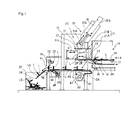
Fig. 1 is a diagram showing an embodiment of the label sheet manufacturing device of the present invention. -
Fig. 2(a) is a diagram showing the operation of the label sheet manufacturing device in the embodiment of the present invention. -
Fig. 2(b) is a diagram showing the operation of the label sheet manufacturing device in the embodiment of the present invention. -
Fig. 2(c) is a diagram showing the operation of the label sheet manufacturing device in the embodiment of the present invention. -
Fig. 3(a) is a diagram showing the operation of the label sheet manufacturing device in the embodiment of the present invention. -
Fig. 3(b) is a diagram showing the operation of the label sheet manufacturing device in the embodiment of the present invention. -
Fig. 3(c) is a diagram showing the operation of the label sheet manufacturing device in the embodiment of the present invention. -
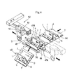
Fig. 4 is a perspective view diagram showing the cutting mechanism of the label sheet manufacturing device in the embodiment of the present invention. -
Fig 5 is a cross-section diagram showing the strip form backing sheet conveyance mechanism of the label sheet manufacturing device in the embodiment of the present invention. -
Fig. 6 is a perspective view diagram showing the label sheet in the embodiment of the present invention. -
Fig. 7 is a diagram showing an example of the conventional label sheet. - Hereinafter, a label sheet manufacturing device according to the embodiments of the present invention is described in detail based on the attached figures.
Figs. 1 ,4 and6 shows the label sheet LS in the embodiment of the present invention. The label LS is formed with a label L temporarily attached to the backing sheet D. The label L in this embodiment is a rectangular shape, wherein a foldedportion 1 is formed by folding and protruding aportion 2 in the middle of the label from back surface side to front surface side in a chevron shape, having afirst side surface 4 and asecond side surface 5 with anapex portion 3 as a border therebetween, and hasouter end portions 7 consecutively provided respectively from a base portion of thefirst side surface 4 and from a base portion of thesecond side surface 5 of the foldedportion 1 viabent portions 6. The label L is applied with an adhesive only on the back surface side surface of theouter end portions 7 or on the entire back surface side surface. Theouter end portions 7 are temporarily attached to the backing sheet D with the foldedportion 1 in a protruding state. That is, the label is temporarily attached to the backing sheet D in a state with the foldedportion 1 folding and uprising in advance. - Furthermore, in the embodiment, on at least one of either the
first side surface 4 or thesecond side surface 5 of the label L, for example, an RFID (Radio Frequency Identification) tag T is provided. The RFID tag T, is comprised of an IC (Integrated Circuit) chip which stores all sorts of information, and an antenna for communication which is connected to the IC chip, and is prevailing in the recent years. In addition, it is needless to mention that, in the present invention, the label L is not necessarily limited to the label L with an RFID tag T, but it can be a label L without a RFID tag T.
Still furthermore, at the folding lines P of theapex portion 3 and thebent portions 6, perforations may be formed. In addition, it is needless to mention that the label L of the label sheet LS of this embodiment is not necessarily in a rectangular shape, but it may be in various types of shape such as a label with an intermediate portion of the label in a variant form. - Furthermore, the backing sheet D is a backing sheet formed by cutting the strip form backing sheet Da, for example, by each one label L or by each set of plurality of labels L accordingly. In this embodiment, the backing sheet D is formed at a predetermined length such that some blank space is left, corresponding to each one label L. At the both end edge portions along the longitudinal direction of the strip form backing sheet Da, holes d, in which the later mentioned pins of the feed roller are inserted, are provided with predetermined interval.
- Next, the label sheet manufacturing device according to the embodiments of the present invention will be described. As shown in
Figs. 1 through 5 , the label sheet manufacturing device is provided with alabel supplying unit 10 which supplies the planar label L.
The label L, at first, is temporarily attached in a line onto the strip form base backing sheet Dd in a planar state as shown inFigs. 1 and2 (a) . Th e label L is temporarily attached onto the strip form base backing sheet with the folding lines P (shown inFig. 6 ) of theapex portion 3 and thebent portions 6 perpendicular to the longitudinal direction (the supplying direction R of the label L) of the strip form base backing sheet Dd.
Thelabel supplying unit 10, as shown inFigs. 1 and2 (a) , sends out the label L by peeling off the label L from the strip form base backing sheet Db on which the label L was temporarily attached in a planar state. Then thelabel supply unit 10, by a peel-offboard 11, peels off the label L from the strip form base backing sheet Db which was supplied to the conveyance route from the not shown supply reel. Then thelabel supplying unit 10 takes up the strip form base backing sheet Db, on which the label L is peeled off, by the not shown take-up reel. The peel-offboard 11, by folding back the strip form base backing sheet Db conveyed through the conveyance route of the strip form base backing sheet Db, peels off the label L, of which the rigidity is larger than that of the strip form base backing sheet Db, from the strip form base backing sheet Db, feeds out and supplies the label L. In the diagram, thereference number 12 is the reader/writer which rewrites the data on the IC chip of the RFID tag T and which performs the verification, etc. by writing and reading of information. In the diagram, thereference number 13 is the thermal head for printing on the label L and thereference number 14 is the platen. - Furthermore, the label sheet manufacturing device is provided with a
label holding unit 20 which attracts and holds the label L supplied from thelabel supplying unit 10. Thelabel holding unit 20 is provided with an attracting and holdingboard 21. The attracting and holdingboard 21 attracts and hold the front surface side of the label L peeled off by the peel-offboard 11. At the attracting and holdingboard 21, a plurality of small holes (not shown in the diagram) which attracts and holds the surface of the label L by air suction is provided. The attracting and holdingboard 21 is divided and formed by the line perpendicular to the supplying direction R of the label L, in other words, the line parallel to the folding lines P of theapex portion 3 and thebent portions 6 of the label L, and configured and provided with a pair of dividedbodies - Still furthermore, the label sheet manufacturing device is provided with a folding and temporary attaching
unit 30. The folding and temporary attachingunit 30 is provided with anair cylinder unit 22, as a transferring unit transferring the attracting and holdingboard 21 of thelabel holding unit 20, to the two positions; the attracting and holding position X (inFigs. 1 and2 ) where the label attracting and holdingboard 21 of thelabel holding unit 20 attracts and holds the label L, and to the temporary attaching position Y (inFig. 3(b) ) where the label L attracted and held at the folded portion forming position K by the divided bodies (a first divided body) 21 A and (a second divided body) 21 B are temporarily attached to the strip form backing sheet Da conveyed by the later mentioned backing sheet conveyance unit. In other words, by theair cylinder unit 22 comprising of acylinder 22a and apiston 22b, the attracting and holdingboard 21 is transferred to the attracting and holding position X (inFigs. 1 and2 ) at which the label L is attracted and held, and to the temporary attaching position Y (inFig. 3(b) ) at which the label L is temporarily attached to the strip form backing sheet Da. Thecylinder 22a of theair cylinder unit 22 is supported by amachine base 15, and a fixingboard 23 supporting the attracting and holdingboard 21 is assembled at the end of thepiston 22b. - Furthermore, the temporary attaching position Y, in relation to the attracting and holding position X, is configured at the downstream side of the conveyance direction R of the strip form backing sheet Da. The
air cylinder unit 22 is supported by themachine base 15 so as to transfer thelabel holding unit 20 from the attracting and holding position X to the temporary attaching position Y in a oblique direction such that the advancing direction of thepiston 22b is oblique. Theair cylinder 22 transfers thelabel holding unit 20 from the attracting and holding position X towards the temporary attaching position Y in an oblique direction such that thelabel holding unit 20 moves away from thelabel supplying unit 10. Therefore, compared to the case where the label holding unit is transferred in a vertical direction, it is possible to reliably prevent the interference with thelabel supplying unit 10. - Furthermore, near the peel-off
board 11, anair blowing pipe 24 which assists attracting and holding of the label L by the attracting and holdingboard 21 at the attracting and holding position X of the attracting and holdingboard 21 is provided. Theair blowing pipe 24 blows the air towards the attracting and holdingboard 21 side from the back surface side of the label L peeled off by the peel-offboard 11. In addition, theair blowing pipe 24, at the later mentioned separating position J of the second dividedbody 21 B (other divided body), also has a function to press theportion 2 of the label L from the back surface side to the front surface side such that theportion 2 of the label L is inserted by protruding in between the first dividedbody 21 A (one divided body) and the second dividedbody 21 B. - Then, the folding and temporary attaching
unit 30, at the attracting and holding position X of the attracting and holdingboard 21 of thelabel holding unit 20, folds and protrudes a portion of the label L held by thelabel holding unit 20 from the back surface side to the front surface side in a chevron shape, and forms the foldedportion 1 having thefirst side face 4 and thesecond side face 5 with theapex portion 3 as a border therebetween. The folding and temporary attachingunit 30 also temporarily attachesouter end portions 7 consecutively provided respectively from the base portion of thefirst side surface 4 and from the base of thesecond side surface 5 of the foldedportion 1 via thebent portions 6 to the strip form backing sheet Da. The folding and temporary attachingunit 30 constitutes the attracting and temporary holdingboard 21 comprising the above-mentioneddivided bodies - In detail, the first divided
body 2 1 A is supported against theattachment plate 23 via the supportingmember 25. The second dividedbody 21 B is supported such that it is movable along the supplying direction R of the label L. And the folding and temporary attachingunit 30 is provided with theair cylinder unit 31 as the folding unit, which relatively approaches and separates the dividedbodies 2 1 A and 21B, and which, at approach of the dividedbodies portion 1 by pressing thebent portions 6 of the label L with the end surfaces 28 at which each dividedbodies part 2 of the label L. Thisair cylinder unit 31 approaches and separates the second dividedbody 21 B to and from the first dividedbody 21 A. Theair cylinder unit 31 is comprised of a cylinder 31 a fixed to theattachment plate 23, and apiston 31b on which the second dividedbody 21B is assembled. This makes the directions, the label L supplying direction R of thelabel supplying unit 10 and the approaching and separating direction of the dividedbodies - Furthermore, the folding and temporary attaching
unit 30 is provided with a movement control unit (not shown in the diagram) which is achieved by the function of the CPU, etc. controlling the movement of the dividedbodies body 21 B to the contacting position S (in solid lines inFig. 2 ) where the dividedbodies label supplying unit 10 is attracted and held, to the separating position J (inFig. 2(a) andFig. 3(c) ) where the dividedbodies Figs. 3(a) and (b) ) where the dividedbodies portion 1, from the separating position J. As the label L is attached by abutting thefirst side face 4 and thesecond side face 5 of the label L, the folded portion forming position K is set at the same position as the contacting position S where thefirst side face 4 and thesecond side face 5 of the label L are abutted. - The separating position J of the divided
bodies bodies bent portions 6 of the label L. The first dividedbody 21A is prepared with a length corresponding to the length of theouter end portions 7 of the label L. The first dividedbody 21 A is set at the same position as thebent portions 6 of the label L supplied from thelabel supplying unit 10, at the position where the outer end portions 28a of the end surfaces 28 contacting the label L. The second dividedbody 21B moves as it attracts and holds the label L and is set such that, at the separating position J, the end portions 28a are at the same positions as thebent portions 6 of the label L. At the separating position J, a space is formed between the first dividedbody 21 A and the second dividedbody 21B in which theportion 2 of the label L protruding from the back surface side to the front surface side can be inserted. Also, at the separating position J, the first dividedbody 21 A and the second dividedbody 21 B attract and hold bothouter end portions 7 of the label L supplying direction R respectively. - In addition, the label sheet manufacturing device is provided with a backing sheet conveyance unit which conveys the strip form backing sheet Da. As shown in
Figs. 1 and5 , the backingsheet conveyance unit 40 is configured to comprise backing sheetreel holding unit 42 which holds thebacking sheet reel 41 with the strip form backing sheet Da wound around rotatably, a strip form backingsheet conveyance mechanism 43 which conveys the strip form backing sheet Da by pulling out the strip form backing sheet Da from thebacking sheet reel 41 held by the backing sheetreel holding unit 42, and a supportingboard 44 which supports the strip form backing sheet Da conveyed by the strip form backingsheet conveyance mechanism 43 at temporary attachment of the label L by the folding and temporary attachingunit 30. - The strip form backing
sheet conveyance mechanism 43, as shown inFigs. 1 and5 , is provided at the downstream end side of the supportingboard 44. The strip form backingsheet conveyance mechanism 43 is also comprises a pair of feedingroller 46 provided with a projecting equally-spaced plurality ofpins 45 which are inserted into the holes d at both end edge portions of the strip form backing sheet Da. Furthermore, the strip form backingsheet conveyance mechanism 43 is provided with amotor 48 which intermittently rotates and drives the feedingroller 46 via thebelt transmission mechanism 47. In addition, at the upper side of the feedingroller 46, provided is a pair ofguide members 49 with openings 49a facing thepins 45 of the feedingroller 46 as shown inFigs 4 and5 , which guides the strip form backing sheet Da from both sides by slidingly contacting both end edge portions of the strip form backing sheet Da. - Furthermore, as shown in
Figs 1 and4 , at the downstream side of the supportingboard 44, acutting mechanism 50 which cuts the strip form backing sheet Da with the label L temporarily attached into a predetermined length, is provided. Thecutting mechanism 50 is configured to comprise arotating blade 51 which cuts the strip form backing sheet Da, a supportingmember 52 which can support and move thecutting blade 51 back and forth in the direction perpendicular to the conveying direction of the strip form backing sheet Da, arail 53 which supports and enables the supportingmember 52 to move back and forth, an actuator (not shown in the diagram) which moves the supportingmember 52 back and forth, and a fixedblade 54 opposing therotating blade 51. InFig. 1 , thereference number 55 represents a stacker which stores the cut label sheets LS. - Therefore, when manufacturing label sheets by the label sheet manufacturing device of the present embodiment, the process will be as follows.
First, as shown inFig. 2(a) , the attracting and holdingplate 21 is positioned at the attracting and holding position X by theair cylinder unit 22, and the second dividedbody 21 B is positioned at the contacting position S (in solid lines inFig. 2(a) ) by theair cylinder unit 31.
In this state, when the label L is conveyed from thelabel supplying unit 10 and then the label L is folded back by the peel-offboard 11 peeled off from the strip form backing sheet Db, the attracting and holdingboard 21 attracts and holds the label L at the attracting and holding position X.
Next, as shown inFigs. 2(a) and 2(b) , theair cylinder 31 operates and moves the second dividedbody 21 B to the separating position J. In this case, between the first dividedbody 21 A and the second dividedbody 21 B, a space where it is possible to insert aportion 2 of the label L protruding from the back surface side (the adhesive layer side) to the front surface side (the indication layer side) is formed. - In this state, as shown in
Figs. 2(c) and3(a) , theair cylinder 31 operates and moves the second dividedbody 21 B from the separating position J to the folded portion forming position K. Furthermore, at this state, the air is blown out from theair blowing pipe 24. Thereby, the foldedportion 1 is formed by the first dividedbody 2 1 A and the second dividedbody 21B respectively attracting and holding the bothouter end portions 7 of the supplying direction R of the label L, and pressing thebent portion 6 of thefirst side face 4 and thebent portion 6 of thesecond side face 5 in the direction of which the back surfaces of thefirst side face 4 and thesecond side face 5 approach the other. In this case, as theportion 2 of the label L is pushed from the back surface side to the front surface side by the air blowing force from theair blowing pipe 24, theportion 2 of the label L will be securely folded in a chevron shape. - Then, as shown in
Fig. 3 (b) , theair cylinder unit 22 operates and moves the attracting and holdingboard 21 from the attracting and holding position X to the temporary attaching position Y, thereby the attracted and held label L is temporarily attached to the strip form backing sheet Da. In this case, the bothouter end portions 7 of the foldedportion 1, which are theportion 2 of the label L protruded in a chevron shape, are pressed to the strip form backing sheet Da by the first dividedbody 21 A and the second dividedbody 21B and the label L is securely temporarily attached to the strip form backing sheet Da. After temporarily attaching the label L, as shown inFig. 3(c) , the second dividedbody 2 1 B of the attracting and holdingboard 21 is positioned at the separating position J. And the attracting and holdingboard 21 is returned to the attracting and holding position X by theair cylinder unit 22. - Meanwhile, at the backing
sheet conveyance unit 40, by intermittently driving themotor 48 of the strip form backingsheet conveyance mechanism 43, the feedingroller 46 conveys the strip form backing sheet Da for a predetermined length (in the embodiment, it is a predetermined length corresponding to the length of a piece of temporarily attached label L). Then, when the strip form backing sheet Da with the label L temporarily attached reaches the predetermined position of the fixedblade 54, therotating blade 51 of thecutting mechanism 50 is moved along the fixedblade 54, and the strip form backing sheet Da is cut, and the label sheet LS is produced. In this way, the label sheets LS are sequentially manufactured. The label sheets LS are dropped to thestacker 55 and stored. - When attaching label L the article using such label sheet LS, the label L is peeled off from the backing sheet D and the
outer end portions 7 are attached to the article as it is by manual procedures. In this case, as shown inFig. 6 , as theapex portion 3 and thebent portions 6 of the label L are folded in advance forming the foldedportion 1, the label L is temporarily attached to the backing sheet D with the foldedportion 1 in a protruding state. Therefore, in the attaching procedure of the label L, it is not required to perform the folding procedure one by one as in the past, but is only required to attach theouter end portions 7 to the article as they are, such that the attaching procedure can be easily performed.
Furthermore, in case a RFID tag T is provided on the label L of the label sheet LS, it is possible to attach the label L more efficiently and easily by manual procedures on articles which cannot be conveyed by the conveyer, etc. such as containers, drums, and iron poles. In addition, as shown inFig. 6 , by configuring the tag T at a position away from the bothouter end portions 7, in case the article is of metals or contains liquid such as water, as the factors which may decrease the radio waves emitted by the tag T are avoided, it is possible to perform good communication. - In addition, in the label sheet manufacturing device of the above embodiment, by changing the stroke of the
air cylinder unit 31 controlled by the movement control unit of theair cylinder 31 accordingly, the label L may be temporarily attached to the backing sheet D by folding the foldedportion 1 and forming a space between thefirst side face 4 and thesecond side face 5 of the label L as it were in an inverted V-shape, and therefore may be changed accordingly. -
- LS
- label sheet
- L
- label
- D
- backing sheet
- Da
- strip form backing sheet
- d
- hole
- Db
- strip form base backing sheet
- 1
- folded portion
- 2
- portion
- 3
- apex portion
- 4
- first side surface (one side surface)
- 5
- second side surface (other side surface)
- 6
- bent portion
- 7
- outer end portion
- T
- RFID tag
- 10
- label supplying unit
- 11
- peel-off board
- 12
- reader/writer
- 13
- thermal head
- 14
- platen
- 15
- machine base
- 20
- label holding unit
- 21
- attracting and holding unit
- 21A
- first divided body (one divided body)
- 21B
- second divided body (other divided body)
- X
- attracting and holding position
- Y
- temporary attaching position
- 22
- air cylinder unit (transferring unit)
- 24
- air blowing pipe
- 30
- folding and temporary attaching unit
- 31
- air cylinder unit (folding unit))
- S
- contacting position
- J
- separation position
- K
- folded portion forming position
- 40
- backing sheet conveyance unit
- 41
- backing sheet reel
- 42
- backing sheet reel holding unit
- 43
- strip form backing sheet conveyance mechanism
- 44
- supporting board
- 45
- pin
- 46
- feeding roller
- 47
- belt transmission mechanism
- 48
- motor
- 49
- guide member
- 50
- cutting mechanism
- 51
- rotating blade
- 52
- supporting member
- 53
- rail
- 54
- fixed blade
- 55
- stacker
- Patent Literature Japanese Utility Model Application, First Publication No.
3073917
Claims (7)
- A label sheet with a label temporarily attached to a backing sheet in a detachable manner, wherein,
a folded portion of the label is formed by folding and protruding an intermediate portion of the label from back surface side to front surface side in a chevron shape, having one side surface and other side surface with an apex portion as a border therebetween, and wherein outer end portions, consecutively provided respectively from a base portion of the one side surface and from a base portion of the other side surface of the folded portion via bent portions, are temporarily attached to the backing sheet with the folded portion in a protruding state. - A label sheet manufacturing device manufacturing a label sheet with the label temporarily attached to a backing sheet in a detachable manner, wherein a folded portion of the label is formed by folding and protruding an intermediate portion of the label from back surface side to front surface side in a chevron shape, having one side surface and other side surface with an apex portion as a border therebetween, and wherein outer end portions, consecutively provided respectively from a base portion of the one side surface and from a base portion of the other side surface of the folded portion via bent portions, are temporarily attached to the backing sheet with the folded portion in a protruding state, the label sheet manufacturing device comprising:a label supply unit which supplies planar label;a label holding unit which attracts and holds the label supplied from the label supply unit;a backing sheet conveyance unit which conveys the backing sheet;a folding and temporary attaching unit , wherein a folded portion of the label is formed by folding and protruding a portion of the label from back surface side to front surface side in a chevron shape, having one side surface and other side surface with an apex portion as a border therebetween, and wherein outer end portions, consecutively provided respectively from a base portion of the one side surface and from a base portion of the other side surface of the folded portion via bent portions, are temporarily attached to the backing sheet conveyed by the backing sheet conveyance unit.
- The label sheet manufacturing device according to claim 2 wherein the label holding unit is configured to comprise a pair of divided bodies which attracts and holds the label; and wherein the folding and temporary attaching unit is configured to comprise a folding unit, which relatively approaches and separates the each divided bodies, and at approach of the divided bodies, forms the folded portion by pressing the bent portions of the label with end surfaces of which each divided bodies are opposing, and folding a part of the label; and a movement control unit which controls the movement of the divided bodies of the folding unit.
- The label sheet manufacturing device according to claim 2 or 3, wherein the backing sheet conveyance unit is configured by a backing sheet reel holding portion which holds the backing sheet reel with the strip form backing sheet wound around rotatably, and a strip form backing sheet conveyance mechanism which pulls out and conveys the strip form backing sheet from the backing sheet reel held by the backing sheet holding unit.
- The label sheet manufacturing device according to claim 4, wherein, at a downstream side of the strip form backing sheet conveyance mechanism, a cutting mechanism, which cuts the strip form backing sheet with the label temporarily attached into a predetermined length, is provided.
- The label sheet manufacturing device according to any of the claims 2 through 5, wherein the folding and temporary attaching unit is provided with a transferring unit which transfers the label holding unit to the two positions, the attracting and holding position where the label is attracted and held by the label holding unit, and the temporary attaching position where the attracted and held label is temporarily attached on the backing sheet.
- The label sheet manufacturing device according to claim 4 or 5, wherein the folding and temporary attaching unit is provided with a transferring unit which transfers the label holding unit to the two positions, the attracting and holding position where the label is attracted and held, and the temporary attaching and holding position where the attracted and held label is temporarily attached to the strip form backing sheet; wherein the temporary attaching position is set at a downstream side of the conveying direction of the strip form backing sheet with regard to the attracting and holding position; and wherein the transferring unit transfers the label holding unit from the attracting and holding position towards the temporary attaching position in an oblique direction.
Applications Claiming Priority (2)
| Application Number | Priority Date | Filing Date | Title |
|---|---|---|---|
| JP2007320123A JP4664960B2 (en) | 2007-12-11 | 2007-12-11 | Label sheet making device |
| PCT/JP2008/053073 WO2009075117A1 (en) | 2007-12-11 | 2008-02-22 | Label sheet and label sheet producing device |
Publications (3)
| Publication Number | Publication Date |
|---|---|
| EP2221794A1 true EP2221794A1 (en) | 2010-08-25 |
| EP2221794A4 EP2221794A4 (en) | 2015-04-29 |
| EP2221794B1 EP2221794B1 (en) | 2018-03-21 |
Family
ID=40755365
Family Applications (1)
| Application Number | Title | Priority Date | Filing Date |
|---|---|---|---|
| EP08711841.0A Not-in-force EP2221794B1 (en) | 2007-12-11 | 2008-02-22 | Label sheet producing device |
Country Status (4)
| Country | Link |
|---|---|
| US (1) | US8695670B2 (en) |
| EP (1) | EP2221794B1 (en) |
| JP (1) | JP4664960B2 (en) |
| WO (1) | WO2009075117A1 (en) |
Families Citing this family (6)
| Publication number | Priority date | Publication date | Assignee | Title |
|---|---|---|---|---|
| JP4733734B2 (en) * | 2008-12-25 | 2011-07-27 | 株式会社サトー知識財産研究所 | Labeling device |
| DE102014102296A1 (en) | 2014-02-21 | 2015-08-27 | Deutsche Telekom Ag | Adhesive label with antenna element and method of shaping |
| JP6132800B2 (en) * | 2014-03-31 | 2017-05-24 | サトーホールディングス株式会社 | IC tag issuing device |
| US20160267818A1 (en) * | 2015-03-12 | 2016-09-15 | Kevin Lindberg | Apparatus and system for the marking and identification of various materials |
| US10399361B2 (en) * | 2017-11-21 | 2019-09-03 | Datamax-O'neil Corporation | Printer, system and method for programming RFID tags on media labels |
| USD959852S1 (en) * | 2017-12-15 | 2022-08-09 | Avery Dennison Retail Information Services Llc | Soccer field label |
Family Cites Families (23)
| Publication number | Priority date | Publication date | Assignee | Title |
|---|---|---|---|---|
| JP2530936Y2 (en) * | 1989-11-20 | 1997-04-02 | 株式会社ニコン | Light leakage prevention device |
| JP2784486B2 (en) | 1989-08-31 | 1998-08-06 | 東芝メカトロニクス株式会社 | Form feeder |
| JPH0388661U (en) * | 1989-12-28 | 1991-09-10 | ||
| GB2289664B (en) * | 1994-05-27 | 1998-04-29 | Instance Ltd David J | Labels and manufacture thereof |
| US6627033B1 (en) * | 1996-05-27 | 2003-09-30 | U-Seal, Inc. | Contact adhesive patterns for sheet stock precluding adhesion of facing sheets in storage |
| JP3088661B2 (en) | 1996-07-23 | 2000-09-18 | 株式会社シマノ | Method and apparatus for transmitting detection signal in bicycle |
| US6350342B1 (en) * | 1996-09-09 | 2002-02-26 | Tamarack Products Inc. | Method of making integrated label products |
| US5800894A (en) * | 1997-09-28 | 1998-09-01 | Brunswick Corporation | Masking device with handle |
| DE69814358T2 (en) * | 1997-12-15 | 2004-04-01 | Engineered Products & Services Inc., Brookfield | HIGH-TEMPERATURE-RESISTANT MASKING DEVICE WITH LASHES |
| JP2000003941A (en) | 1998-06-16 | 2000-01-07 | Seiko Epson Corp | Flexible circuit board |
| JP4262899B2 (en) * | 2000-02-17 | 2009-05-13 | 株式会社日研生物医学研究所 | Seal production tape |
| JP3073917U (en) | 2000-06-08 | 2000-12-15 | 株式会社ともプラン | Advertisement seals such as price tags |
| JP2002001424A (en) | 2000-06-26 | 2002-01-08 | Masaaki Nagakura | Method for manufacturing component for super critical water oxidization treatment |
| JP3088661U (en) * | 2002-03-18 | 2002-09-20 | 株式会社アックスコーポレーション | 3D sign sheet |
| US20040238098A1 (en) * | 2002-05-14 | 2004-12-02 | Bleckmann Frederick August | Method and apparatus for production of RF labels |
| JP2004051180A (en) * | 2002-07-22 | 2004-02-19 | Risu Pack Co Ltd | Label for stretch film |
| GB0308934D0 (en) * | 2003-04-17 | 2003-05-28 | Field Group Plc | Labels and method of manufacture thereof |
| ATE451681T1 (en) * | 2004-09-06 | 2009-12-15 | Upm Raflatac Oy | LABEL |
| JP2006277524A (en) * | 2005-03-30 | 2006-10-12 | Sato Corp | RFID label and its attaching method |
| US7703685B2 (en) * | 2005-04-08 | 2010-04-27 | Kabushiki Kaisha Sato | Label application device |
| WO2007013357A1 (en) * | 2005-07-29 | 2007-02-01 | Kabushiki Kaisha Sato | Rfid label attaching method, rfid label attaching device, and rfid label |
| DE112006002484T5 (en) * | 2005-09-14 | 2009-02-26 | Kabushiki Kaisha Sato | Label affixing apparatus |
| JP2008273569A (en) * | 2007-04-27 | 2008-11-13 | Sato Corp | Labeling device |
-
2007
- 2007-12-11 JP JP2007320123A patent/JP4664960B2/en not_active Expired - Fee Related
-
2008
- 2008-02-22 EP EP08711841.0A patent/EP2221794B1/en not_active Not-in-force
- 2008-02-22 WO PCT/JP2008/053073 patent/WO2009075117A1/en not_active Ceased
- 2008-02-22 US US12/744,209 patent/US8695670B2/en active Active
Non-Patent Citations (1)
| Title |
|---|
| See references of WO2009075117A1 * |
Also Published As
| Publication number | Publication date |
|---|---|
| EP2221794B1 (en) | 2018-03-21 |
| JP2009145428A (en) | 2009-07-02 |
| JP4664960B2 (en) | 2011-04-06 |
| US20100247871A1 (en) | 2010-09-30 |
| EP2221794A4 (en) | 2015-04-29 |
| WO2009075117A1 (en) | 2009-06-18 |
| US8695670B2 (en) | 2014-04-15 |
Similar Documents
| Publication | Publication Date | Title |
|---|---|---|
| EP2221794B1 (en) | Label sheet producing device | |
| KR101119503B1 (en) | Double-face printing label printer | |
| JP5395080B2 (en) | Label separation and application apparatus and method | |
| CN101107641A (en) | Improved label and applicator therefor | |
| CN102815086A (en) | Printing system | |
| JP5390172B2 (en) | Label continuous body without mount and method for producing label continuous without mount | |
| KR101046671B1 (en) | Label sticking device | |
| JP6310685B2 (en) | RFID tag issuing device | |
| WO2008044663A1 (en) | Large-size inlet manufacturing method, inlet-equipped tape, its manufacturing method, and its manufacturing device | |
| JP2002134635A (en) | IC label manufacturing apparatus and manufacturing method | |
| JP2007094977A (en) | Inlet feeder | |
| US20050178037A1 (en) | Hangtags for use with an automatic tag attacher/printer | |
| JP2012218804A (en) | Label attaching system for plate-like member | |
| WO2010035352A1 (en) | Backless label stacker device in printer, and label stacking method | |
| JP2021142630A (en) | Cutting transfer device and label manufacturing device and cutting transfer method and label manufacturing method | |
| JP2011207494A (en) | Label applicator | |
| JP4769071B2 (en) | Labeling device | |
| JP4769066B2 (en) | Labeling device | |
| JP2004075075A (en) | Folding case and its manufacturing method | |
| JP2011121264A (en) | Electronic tag affixing device and method of affixation | |
| JP2001354220A (en) | Automatic sticking device | |
| JP2004001813A (en) | Label separation device | |
| JP2019189246A (en) | Label delivery mechanism, and label sticking apparatus | |
| JPS63272647A (en) | Method and device for manufacturing separable small piece | |
| JP2007168179A (en) | Label continuum manufacturing method and label continuum |
Legal Events
| Date | Code | Title | Description |
|---|---|---|---|
| PUAI | Public reference made under article 153(3) epc to a published international application that has entered the european phase |
Free format text: ORIGINAL CODE: 0009012 |
|
| 17P | Request for examination filed |
Effective date: 20100609 |
|
| AK | Designated contracting states |
Kind code of ref document: A1 Designated state(s): AT BE BG CH CY CZ DE DK EE ES FI FR GB GR HR HU IE IS IT LI LT LU LV MC MT NL NO PL PT RO SE SI SK TR |
|
| AX | Request for extension of the european patent |
Extension state: AL BA MK RS |
|
| RIN1 | Information on inventor provided before grant (corrected) |
Inventor name: HORN, KLAUS Inventor name: WELLSANDT, MARTIN Inventor name: S. BARCZYK, VICTOR |
|
| DAX | Request for extension of the european patent (deleted) | ||
| RA4 | Supplementary search report drawn up and despatched (corrected) |
Effective date: 20150401 |
|
| RIC1 | Information provided on ipc code assigned before grant |
Ipc: B65H 41/00 20060101ALI20150326BHEP Ipc: G09F 3/02 20060101AFI20150326BHEP Ipc: G09F 3/10 20060101ALI20150326BHEP Ipc: B31D 1/02 20060101ALI20150326BHEP |
|
| 17Q | First examination report despatched |
Effective date: 20161011 |
|
| STAA | Information on the status of an ep patent application or granted ep patent |
Free format text: STATUS: EXAMINATION IS IN PROGRESS |
|
| GRAP | Despatch of communication of intention to grant a patent |
Free format text: ORIGINAL CODE: EPIDOSNIGR1 |
|
| STAA | Information on the status of an ep patent application or granted ep patent |
Free format text: STATUS: GRANT OF PATENT IS INTENDED |
|
| INTG | Intention to grant announced |
Effective date: 20170928 |
|
| GRAS | Grant fee paid |
Free format text: ORIGINAL CODE: EPIDOSNIGR3 |
|
| RAP1 | Party data changed (applicant data changed or rights of an application transferred) |
Owner name: SATO HOLDINGS KABUSHIKI KAISHA |
|
| GRAA | (expected) grant |
Free format text: ORIGINAL CODE: 0009210 |
|
| STAA | Information on the status of an ep patent application or granted ep patent |
Free format text: STATUS: THE PATENT HAS BEEN GRANTED |
|
| AK | Designated contracting states |
Kind code of ref document: B1 Designated state(s): AT BE BG CH CY CZ DE DK EE ES FI FR GB GR HR HU IE IS IT LI LT LU LV MC MT NL NO PL PT RO SE SI SK TR |
|
| REG | Reference to a national code |
Ref country code: GB Ref legal event code: FG4D |
|
| REG | Reference to a national code |
Ref country code: CH Ref legal event code: EP |
|
| REG | Reference to a national code |
Ref country code: AT Ref legal event code: REF Ref document number: 981887 Country of ref document: AT Kind code of ref document: T Effective date: 20180415 |
|
| REG | Reference to a national code |
Ref country code: IE Ref legal event code: FG4D |
|
| REG | Reference to a national code |
Ref country code: DE Ref legal event code: R096 Ref document number: 602008054498 Country of ref document: DE |
|
| REG | Reference to a national code |
Ref country code: NL Ref legal event code: MP Effective date: 20180321 |
|
| PG25 | Lapsed in a contracting state [announced via postgrant information from national office to epo] |
Ref country code: HR Free format text: LAPSE BECAUSE OF FAILURE TO SUBMIT A TRANSLATION OF THE DESCRIPTION OR TO PAY THE FEE WITHIN THE PRESCRIBED TIME-LIMIT Effective date: 20180321 Ref country code: CY Free format text: LAPSE BECAUSE OF FAILURE TO SUBMIT A TRANSLATION OF THE DESCRIPTION OR TO PAY THE FEE WITHIN THE PRESCRIBED TIME-LIMIT Effective date: 20180321 Ref country code: LT Free format text: LAPSE BECAUSE OF FAILURE TO SUBMIT A TRANSLATION OF THE DESCRIPTION OR TO PAY THE FEE WITHIN THE PRESCRIBED TIME-LIMIT Effective date: 20180321 Ref country code: NO Free format text: LAPSE BECAUSE OF FAILURE TO SUBMIT A TRANSLATION OF THE DESCRIPTION OR TO PAY THE FEE WITHIN THE PRESCRIBED TIME-LIMIT Effective date: 20180621 Ref country code: FI Free format text: LAPSE BECAUSE OF FAILURE TO SUBMIT A TRANSLATION OF THE DESCRIPTION OR TO PAY THE FEE WITHIN THE PRESCRIBED TIME-LIMIT Effective date: 20180321 |
|
| REG | Reference to a national code |
Ref country code: LT Ref legal event code: MG4D |
|
| REG | Reference to a national code |
Ref country code: AT Ref legal event code: MK05 Ref document number: 981887 Country of ref document: AT Kind code of ref document: T Effective date: 20180321 |
|
| PG25 | Lapsed in a contracting state [announced via postgrant information from national office to epo] |
Ref country code: GR Free format text: LAPSE BECAUSE OF FAILURE TO SUBMIT A TRANSLATION OF THE DESCRIPTION OR TO PAY THE FEE WITHIN THE PRESCRIBED TIME-LIMIT Effective date: 20180622 Ref country code: BG Free format text: LAPSE BECAUSE OF FAILURE TO SUBMIT A TRANSLATION OF THE DESCRIPTION OR TO PAY THE FEE WITHIN THE PRESCRIBED TIME-LIMIT Effective date: 20180621 Ref country code: LV Free format text: LAPSE BECAUSE OF FAILURE TO SUBMIT A TRANSLATION OF THE DESCRIPTION OR TO PAY THE FEE WITHIN THE PRESCRIBED TIME-LIMIT Effective date: 20180321 Ref country code: SE Free format text: LAPSE BECAUSE OF FAILURE TO SUBMIT A TRANSLATION OF THE DESCRIPTION OR TO PAY THE FEE WITHIN THE PRESCRIBED TIME-LIMIT Effective date: 20180321 |
|
| PG25 | Lapsed in a contracting state [announced via postgrant information from national office to epo] |
Ref country code: RO Free format text: LAPSE BECAUSE OF FAILURE TO SUBMIT A TRANSLATION OF THE DESCRIPTION OR TO PAY THE FEE WITHIN THE PRESCRIBED TIME-LIMIT Effective date: 20180321 Ref country code: ES Free format text: LAPSE BECAUSE OF FAILURE TO SUBMIT A TRANSLATION OF THE DESCRIPTION OR TO PAY THE FEE WITHIN THE PRESCRIBED TIME-LIMIT Effective date: 20180321 Ref country code: PL Free format text: LAPSE BECAUSE OF FAILURE TO SUBMIT A TRANSLATION OF THE DESCRIPTION OR TO PAY THE FEE WITHIN THE PRESCRIBED TIME-LIMIT Effective date: 20180321 Ref country code: NL Free format text: LAPSE BECAUSE OF FAILURE TO SUBMIT A TRANSLATION OF THE DESCRIPTION OR TO PAY THE FEE WITHIN THE PRESCRIBED TIME-LIMIT Effective date: 20180321 Ref country code: EE Free format text: LAPSE BECAUSE OF FAILURE TO SUBMIT A TRANSLATION OF THE DESCRIPTION OR TO PAY THE FEE WITHIN THE PRESCRIBED TIME-LIMIT Effective date: 20180321 |
|
| PG25 | Lapsed in a contracting state [announced via postgrant information from national office to epo] |
Ref country code: AT Free format text: LAPSE BECAUSE OF FAILURE TO SUBMIT A TRANSLATION OF THE DESCRIPTION OR TO PAY THE FEE WITHIN THE PRESCRIBED TIME-LIMIT Effective date: 20180321 Ref country code: CZ Free format text: LAPSE BECAUSE OF FAILURE TO SUBMIT A TRANSLATION OF THE DESCRIPTION OR TO PAY THE FEE WITHIN THE PRESCRIBED TIME-LIMIT Effective date: 20180321 Ref country code: SK Free format text: LAPSE BECAUSE OF FAILURE TO SUBMIT A TRANSLATION OF THE DESCRIPTION OR TO PAY THE FEE WITHIN THE PRESCRIBED TIME-LIMIT Effective date: 20180321 |
|
| PG25 | Lapsed in a contracting state [announced via postgrant information from national office to epo] |
Ref country code: PT Free format text: LAPSE BECAUSE OF FAILURE TO SUBMIT A TRANSLATION OF THE DESCRIPTION OR TO PAY THE FEE WITHIN THE PRESCRIBED TIME-LIMIT Effective date: 20180723 |
|
| REG | Reference to a national code |
Ref country code: DE Ref legal event code: R097 Ref document number: 602008054498 Country of ref document: DE |
|
| PLBE | No opposition filed within time limit |
Free format text: ORIGINAL CODE: 0009261 |
|
| STAA | Information on the status of an ep patent application or granted ep patent |
Free format text: STATUS: NO OPPOSITION FILED WITHIN TIME LIMIT |
|
| PG25 | Lapsed in a contracting state [announced via postgrant information from national office to epo] |
Ref country code: DK Free format text: LAPSE BECAUSE OF FAILURE TO SUBMIT A TRANSLATION OF THE DESCRIPTION OR TO PAY THE FEE WITHIN THE PRESCRIBED TIME-LIMIT Effective date: 20180321 |
|
| 26N | No opposition filed |
Effective date: 20190102 |
|
| PG25 | Lapsed in a contracting state [announced via postgrant information from national office to epo] |
Ref country code: IT Free format text: LAPSE BECAUSE OF FAILURE TO SUBMIT A TRANSLATION OF THE DESCRIPTION OR TO PAY THE FEE WITHIN THE PRESCRIBED TIME-LIMIT Effective date: 20180321 |
|
| PG25 | Lapsed in a contracting state [announced via postgrant information from national office to epo] |
Ref country code: SI Free format text: LAPSE BECAUSE OF FAILURE TO SUBMIT A TRANSLATION OF THE DESCRIPTION OR TO PAY THE FEE WITHIN THE PRESCRIBED TIME-LIMIT Effective date: 20180321 |
|
| REG | Reference to a national code |
Ref country code: CH Ref legal event code: PL |
|
| PG25 | Lapsed in a contracting state [announced via postgrant information from national office to epo] |
Ref country code: LU Free format text: LAPSE BECAUSE OF NON-PAYMENT OF DUE FEES Effective date: 20190222 Ref country code: MC Free format text: LAPSE BECAUSE OF FAILURE TO SUBMIT A TRANSLATION OF THE DESCRIPTION OR TO PAY THE FEE WITHIN THE PRESCRIBED TIME-LIMIT Effective date: 20180321 |
|
| REG | Reference to a national code |
Ref country code: BE Ref legal event code: MM Effective date: 20190228 |
|
| REG | Reference to a national code |
Ref country code: IE Ref legal event code: MM4A |
|
| PG25 | Lapsed in a contracting state [announced via postgrant information from national office to epo] |
Ref country code: CH Free format text: LAPSE BECAUSE OF NON-PAYMENT OF DUE FEES Effective date: 20190228 Ref country code: LI Free format text: LAPSE BECAUSE OF NON-PAYMENT OF DUE FEES Effective date: 20190228 |
|
| PG25 | Lapsed in a contracting state [announced via postgrant information from national office to epo] |
Ref country code: IE Free format text: LAPSE BECAUSE OF NON-PAYMENT OF DUE FEES Effective date: 20190222 |
|
| PG25 | Lapsed in a contracting state [announced via postgrant information from national office to epo] |
Ref country code: BE Free format text: LAPSE BECAUSE OF NON-PAYMENT OF DUE FEES Effective date: 20190228 |
|
| PG25 | Lapsed in a contracting state [announced via postgrant information from national office to epo] |
Ref country code: TR Free format text: LAPSE BECAUSE OF FAILURE TO SUBMIT A TRANSLATION OF THE DESCRIPTION OR TO PAY THE FEE WITHIN THE PRESCRIBED TIME-LIMIT Effective date: 20180321 |
|
| PG25 | Lapsed in a contracting state [announced via postgrant information from national office to epo] |
Ref country code: MT Free format text: LAPSE BECAUSE OF NON-PAYMENT OF DUE FEES Effective date: 20190222 |
|
| PG25 | Lapsed in a contracting state [announced via postgrant information from national office to epo] |
Ref country code: IS Free format text: LAPSE BECAUSE OF FAILURE TO SUBMIT A TRANSLATION OF THE DESCRIPTION OR TO PAY THE FEE WITHIN THE PRESCRIBED TIME-LIMIT Effective date: 20180721 |
|
| PG25 | Lapsed in a contracting state [announced via postgrant information from national office to epo] |
Ref country code: HU Free format text: LAPSE BECAUSE OF FAILURE TO SUBMIT A TRANSLATION OF THE DESCRIPTION OR TO PAY THE FEE WITHIN THE PRESCRIBED TIME-LIMIT; INVALID AB INITIO Effective date: 20080222 |
|
| P01 | Opt-out of the competence of the unified patent court (upc) registered |
Effective date: 20230413 |
|
| PGFP | Annual fee paid to national office [announced via postgrant information from national office to epo] |
Ref country code: DE Payment date: 20240219 Year of fee payment: 17 Ref country code: GB Payment date: 20240219 Year of fee payment: 17 |
|
| PGFP | Annual fee paid to national office [announced via postgrant information from national office to epo] |
Ref country code: FR Payment date: 20240221 Year of fee payment: 17 |
|
| REG | Reference to a national code |
Ref country code: DE Ref legal event code: R119 Ref document number: 602008054498 Country of ref document: DE |
|
| GBPC | Gb: european patent ceased through non-payment of renewal fee |
Effective date: 20250222 |
|
| PG25 | Lapsed in a contracting state [announced via postgrant information from national office to epo] |
Ref country code: DE Free format text: LAPSE BECAUSE OF NON-PAYMENT OF DUE FEES Effective date: 20250902 |
|
| PG25 | Lapsed in a contracting state [announced via postgrant information from national office to epo] |
Ref country code: GB Free format text: LAPSE BECAUSE OF NON-PAYMENT OF DUE FEES Effective date: 20250222 |
|
| PG25 | Lapsed in a contracting state [announced via postgrant information from national office to epo] |
Ref country code: FR Free format text: LAPSE BECAUSE OF NON-PAYMENT OF DUE FEES Effective date: 20250228 |