EP2221411A1 - Electric household washing appliance - Google Patents
Electric household washing appliance Download PDFInfo
- Publication number
- EP2221411A1 EP2221411A1 EP09002510A EP09002510A EP2221411A1 EP 2221411 A1 EP2221411 A1 EP 2221411A1 EP 09002510 A EP09002510 A EP 09002510A EP 09002510 A EP09002510 A EP 09002510A EP 2221411 A1 EP2221411 A1 EP 2221411A1
- Authority
- EP
- European Patent Office
- Prior art keywords
- household appliance
- electric household
- source
- casing
- opening
- Prior art date
- Legal status (The legal status is an assumption and is not a legal conclusion. Google has not performed a legal analysis and makes no representation as to the accuracy of the status listed.)
- Withdrawn
Links
- 238000005406 washing Methods 0.000 title claims abstract description 13
- XLYOFNOQVPJJNP-UHFFFAOYSA-N water Substances O XLYOFNOQVPJJNP-UHFFFAOYSA-N 0.000 claims abstract description 18
- 230000003134 recirculating effect Effects 0.000 claims abstract description 10
- 239000000463 material Substances 0.000 claims description 6
- 230000005855 radiation Effects 0.000 claims description 4
- 238000010412 laundry washing Methods 0.000 claims description 3
- 238000003780 insertion Methods 0.000 claims 1
- 230000037431 insertion Effects 0.000 claims 1
- 230000005674 electromagnetic induction Effects 0.000 description 1
- 230000007257 malfunction Effects 0.000 description 1
- 239000012780 transparent material Substances 0.000 description 1
Images


Classifications
-
- D—TEXTILES; PAPER
- D06—TREATMENT OF TEXTILES OR THE LIKE; LAUNDERING; FLEXIBLE MATERIALS NOT OTHERWISE PROVIDED FOR
- D06F—LAUNDERING, DRYING, IRONING, PRESSING OR FOLDING TEXTILE ARTICLES
- D06F39/00—Details of washing machines not specific to a single type of machines covered by groups D06F9/00 - D06F27/00
- D06F39/08—Liquid supply or discharge arrangements
- D06F39/083—Liquid discharge or recirculation arrangements
-
- D—TEXTILES; PAPER
- D06—TREATMENT OF TEXTILES OR THE LIKE; LAUNDERING; FLEXIBLE MATERIALS NOT OTHERWISE PROVIDED FOR
- D06F—LAUNDERING, DRYING, IRONING, PRESSING OR FOLDING TEXTILE ARTICLES
- D06F2103/00—Parameters monitored or detected for the control of domestic laundry washing machines, washer-dryers or laundry dryers
- D06F2103/64—Radiation, e.g. microwaves
- D06F2103/66—Radiation, e.g. microwaves for treatment of laundry otherwise than by drying, e.g. using UV light
-
- D—TEXTILES; PAPER
- D06—TREATMENT OF TEXTILES OR THE LIKE; LAUNDERING; FLEXIBLE MATERIALS NOT OTHERWISE PROVIDED FOR
- D06F—LAUNDERING, DRYING, IRONING, PRESSING OR FOLDING TEXTILE ARTICLES
- D06F34/00—Details of control systems for washing machines, washer-dryers or laundry dryers
- D06F34/10—Power supply arrangements, e.g. stand-by circuits
Definitions
- the present invention relates to an electric household washing appliance, in particular a laundry washing machine or dishwasher.
- the electric household appliance industry manufactures appliances comprising a casing; a wash tub for housing the articles to be washed, and mounted inside the casing; and a hydraulic feed circuit for feeding mains water into the wash tub and draining water from the wash tub into the drains.
- the appliance also comprises a hydraulic recirculating circuit which is normally operated instead of the hydraulic feed circuit; and a processing unit for processing the water drained from the wash tub along the hydraulic recirculating circuit, and which comprises a UV lamp mounted inside the casing to disinfect the water drained from the wash tub.
- UV lamps being mounted in hard-to-reach parts of the casing, known electric household washing appliances of the above type have various drawbacks, mainly due to replacement of the lamps, in the event of a malfunction, and disposal of the lamps, when the appliance is scrapped, having to be carried out by a service engineer, and being a painstaking, relatively time-consuming job.
- an electric household washing appliance as claimed in the accompanying Claims.
- number 1 indicates as a whole an electric household washing appliance defined, in the example shown, by a laundry washing machine comprising a substantially parallelepiped-shaped casing 2 bounded by a front wall 3 and a rear wall 4 substantially parallel to each other, a top wall 5 and a bottom wall 6 substantially parallel to each other and perpendicular to walls 3 and 4, and two lateral walls 7 substantially parallel to each other and perpendicular to walls 3, 4, 5 and 6.
- Washing machine 1 comprises a substantially cylindrical wash tub 8 housed inside casing 2 and accessible from the outside through a loading door 9 formed through front wall 3; and a hydraulic feed circuit (not shown) for feeding mains water into wash tub 8 and draining the water from wash tub 8 into the drains.
- Washing machine 1 also comprises a hydraulic recirculating circuit 10, which is normally operated instead of the hydraulic feed circuit (not shown), and which in turn comprises a pipe 11 extending between an inlet 12, located at the bottom of wash tub 8 to receive the drain water from wash tub 8, and an outlet 13 fitted to the top of wash tub 8 to feed the water back into wash tub 8.
- a hydraulic recirculating circuit 10 which is normally operated instead of the hydraulic feed circuit (not shown), and which in turn comprises a pipe 11 extending between an inlet 12, located at the bottom of wash tub 8 to receive the drain water from wash tub 8, and an outlet 13 fitted to the top of wash tub 8 to feed the water back into wash tub 8.
- a processing unit 14 comprising an elongated UV lamp 15 having a longitudinal axis 16 and fitted removably to two supporting members 17, which are designed to receive and retain the ends of lamp 15, electrically power lamp 15, and are fitted inside a supporting hatch 18 closing an opening 19 in front wall 3 of casing 2.
- Hatch 18 is fitted to casing 2 to rotate, with respect to casing 2 and about a hinge axis 20 substantially parallel to axis 16, between a closed position ( Figure 3 ), in which hatch 18 is coplanar with front wall 3 to close opening 19, and lamp 15 is positioned facing an intermediate portion of pipe 11, and an open position ( Figure 1 ), in which lamp 15 is accessible from outside casing 2 and can be changed quickly and easily by the user or a service engineer.
- the Figure 4-6 variation differs from the Figure 1-3 embodiment by pipe 11 being replaced by a pipe 24 comprising an annular intermediate portion 25, which has a substantially horizontal longitudinal axis 26 perpendicular to front wall 3, is defined between an outer sleeve 27 and a cup-shaped inner body 28 fitted inside sleeve 27 and coaxial with axis 26, and comprises an outlet 25a and an inlet 25b (it is evident that the aperture 25a can be used as an inlet whereas the aperture 25b can be used as an outlet depending on the direction of the stream of the water flowing along the recirculating circuit 10).
- Body 28 is made at least partially of material transparent to UV radiation, is fitted in fluidtight manner to sleeve 27, and has an open end 29 projecting axially outside sleeve 27 and facing hatch 18.
- Pipe 24 comprises an inlet portion (not shown) connected hydraulically to the bottom of wash tub 8 and to portion 25 for example via inlet 25b; and an outlet portion (not shown) connected hydraulically to the top of wash tub 8 and to portion 25 for example via outlet 25a.
- the water fed along pipe 24 is disinfected by a processing unit 30 comprising an elongated UV lamp 31, which slides inside body 28 and is powered electrically by an electric connector 32, which is connected to lamp 31 by an electric cable 33 and slides inside a socket 34 fitted inside casing 2.
- a processing unit 30 comprising an elongated UV lamp 31, which slides inside body 28 and is powered electrically by an electric connector 32, which is connected to lamp 31 by an electric cable 33 and slides inside a socket 34 fitted inside casing 2.
- Unit 30 is therefore connected removably to body 28 and socket 34 through open and 29, and can be changed quickly and easily by the user or a service engineer once hatch 18 is opened.
- the body 28 forms a wall of the annular intermediate portion 25 so that such wall, at least partially in UV transparent material for allowing the UV lamp to radiate the water, separates the UV lamp from the water flowing along the sleeve 27.
Landscapes
- Engineering & Computer Science (AREA)
- Textile Engineering (AREA)
- Apparatus For Disinfection Or Sterilisation (AREA)
- Physical Water Treatments (AREA)
- Detail Structures Of Washing Machines And Dryers (AREA)
Abstract
Description
- The present invention relates to an electric household washing appliance, in particular a laundry washing machine or dishwasher.
- The electric household appliance industry manufactures appliances comprising a casing; a wash tub for housing the articles to be washed, and mounted inside the casing; and a hydraulic feed circuit for feeding mains water into the wash tub and draining water from the wash tub into the drains.
- As disclosed in documents
DE-4342049-A andUS-6253584-A , the appliance also comprises a hydraulic recirculating circuit which is normally operated instead of the hydraulic feed circuit; and a processing unit for processing the water drained from the wash tub along the hydraulic recirculating circuit, and which comprises a UV lamp mounted inside the casing to disinfect the water drained from the wash tub. - The UV lamps being mounted in hard-to-reach parts of the casing, known electric household washing appliances of the above type have various drawbacks, mainly due to replacement of the lamps, in the event of a malfunction, and disposal of the lamps, when the appliance is scrapped, having to be carried out by a service engineer, and being a painstaking, relatively time-consuming job.
- It is an object of the present invention to provide an electric household washing appliance designed to eliminate the above drawbacks, and which is cheap and easy to produce.
- According to the present invention, there is provided an electric household washing appliance as claimed in the accompanying Claims.
- A non-limiting embodiment of the present invention will be described by way of example with reference to the accompanying drawings, in which:
-
Figure 1 shows a schematic view in perspective and enlarged detail of a preferred embodiment of the electric household washing appliance according to the present invention; -
Figure 2 shows a schematic view in perspective of a first detail of theFigure 1 appliance; -
Figure 3 shows a schematic lateral view of a second detail of theFigure 1 appliance; -
Figure 4 shows a schematic view in perspective of a variation of theFigure 1 appliance; -
Figure 5 shows a partly exploded view in perspective of a variation of theFigure 4 appliance; -
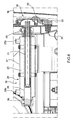
Figure 6 shows a partly sectioned, schematic plan view, with parts removed for clarity, of a detail inFigures 4 and 5 . - With reference to
Figures 1 ,2, and 3 , number 1 indicates as a whole an electric household washing appliance defined, in the example shown, by a laundry washing machine comprising a substantially parallelepiped-shaped casing 2 bounded by afront wall 3 and arear wall 4 substantially parallel to each other, atop wall 5 and abottom wall 6 substantially parallel to each other and perpendicular towalls lateral walls 7 substantially parallel to each other and perpendicular towalls - Washing machine 1 comprises a substantially
cylindrical wash tub 8 housed insidecasing 2 and accessible from the outside through aloading door 9 formed throughfront wall 3; and a hydraulic feed circuit (not shown) for feeding mains water intowash tub 8 and draining the water fromwash tub 8 into the drains. - Washing machine 1 also comprises a hydraulic recirculating
circuit 10, which is normally operated instead of the hydraulic feed circuit (not shown), and which in turn comprises apipe 11 extending between aninlet 12, located at the bottom ofwash tub 8 to receive the drain water fromwash tub 8, and anoutlet 13 fitted to the top ofwash tub 8 to feed the water back intowash tub 8. - The water drained from
wash tub 8 alongpipe 11 is disinfected by aprocessing unit 14 comprising anelongated UV lamp 15 having alongitudinal axis 16 and fitted removably to two supportingmembers 17, which are designed to receive and retain the ends oflamp 15, electricallypower lamp 15, and are fitted inside a supportinghatch 18 closing an opening 19 infront wall 3 ofcasing 2. - Hatch 18 is fitted to
casing 2 to rotate, with respect tocasing 2 and about ahinge axis 20 substantially parallel toaxis 16, between a closed position (Figure 3 ), in whichhatch 18 is coplanar withfront wall 3 to closeopening 19, andlamp 15 is positioned facing an intermediate portion ofpipe 11, and an open position (Figure 1 ), in whichlamp 15 is accessible fromoutside casing 2 and can be changed quickly and easily by the user or a service engineer. - In connection with the above, it should be pointed out that, in the example shown :
- opening 19 is formed through a
bottom portion 21, made of plastic, offront wall 3; - the intermediate portion of
pipe 11 facinglamp 15 is made of material transparent to UV radiation; and -
hatch 18 is symmetrical with ahatch 22 closing anopening 23 formed throughportion 21 to receive a filter (not shown) of washing machine 1. - The
Figure 4-6 variation differs from theFigure 1-3 embodiment bypipe 11 being replaced by apipe 24 comprising an annularintermediate portion 25, which has a substantially horizontallongitudinal axis 26 perpendicular tofront wall 3, is defined between anouter sleeve 27 and a cup-shapedinner body 28 fitted insidesleeve 27 and coaxial withaxis 26, and comprises anoutlet 25a and aninlet 25b (it is evident that theaperture 25a can be used as an inlet whereas theaperture 25b can be used as an outlet depending on the direction of the stream of the water flowing along the recirculating circuit 10). -
Body 28 is made at least partially of material transparent to UV radiation, is fitted in fluidtight manner to sleeve 27, and has anopen end 29 projecting axially outsidesleeve 27 and facinghatch 18. -
Pipe 24 comprises an inlet portion (not shown) connected hydraulically to the bottom ofwash tub 8 and toportion 25 for example viainlet 25b; and an outlet portion (not shown) connected hydraulically to the top ofwash tub 8 and toportion 25 for example viaoutlet 25a. - The water fed along
pipe 24 is disinfected by aprocessing unit 30 comprising anelongated UV lamp 31, which slides insidebody 28 and is powered electrically by anelectric connector 32, which is connected tolamp 31 by anelectric cable 33 and slides inside asocket 34 fitted insidecasing 2. -
Unit 30 is therefore connected removably tobody 28 andsocket 34 through open and 29, and can be changed quickly and easily by the user or a service engineer oncehatch 18 is opened. - In the embodiment described by way of example at
figure 6 , thebody 28 forms a wall of the annularintermediate portion 25 so that such wall, at least partially in UV transparent material for allowing the UV lamp to radiate the water, separates the UV lamp from the water flowing along thesleeve 27. - In variations not shown :
-
hatch 18 and opening 19 are formed inrear wall 4 ofcasing 2; -
hatch 18 and opening 19 are formed in atop control panel 35 or in the upper wall 5 (i.e. in the worktop) of washing machine 1; -
hatch 18 and opening 19 are eliminated, andprocessing unit casing 2 by means ofhatch 22; -
hatch 18 is replaced by a cover fitted preferably, though not necessarily, to one end oflamp casing 2 or defined directly by the same end oflamp hatch 18 shown infigures 4, 5 and6 can be eliminated and theUV lamp 31 is simply removable and insertable through thebody 28 by means of the cover associated to and end of theUV lamp 31 and clearly depicted infigures 4, 5 and particularly infigure 6 ; -
electric cable 33 is eliminated andlamp 31 is powered electrically in a contactless manner (for example via electromagnetic induction); -
hatch 18 is made at least partly of material transparent to visible light but not to UV radiation to allow control of theprocessing unit 14 and/or of the presence oflamp -
lamp
Claims (15)
- An electric household washing appliance, in particular a dishwasher or laundry washing machine, the electric household appliance comprising a wash tub (8) for the articles to be washed; a hydraulic recirculating circuit (10) for feeding water through the wash tub (8); a processing unit (14; 30) for processing the water drained from the wash tub (8) along the hydraulic recirculating circuit (10), the processing unit (14; 30) comprising at least one UV source (15; 31); and a casing (2) housing the wash tub (8) and at least part of the hydraulic recirculating circuit (10); and being characterized in that the casing (2) comprises an opening (19; 23; 29) formed through a wall (3; 4) of the casing (2) and by which to insert and remove the UV source (15; 31) into and from the casing (2).
- An electric household appliance as claimed in Claim 1, and also comprising a hatch (18; 22) or cover closing the opening (19; 23; 29).
- An electric household appliance as claimed in Claim 2, wherein the hatch (18; 22) is fitted to the casing (2) to rotate between an opening position and a closed position opening and closing the opening (19; 23; 29) respectively.
- An electric household appliance as claimed in Claim 2, wherein the cover is fitted removably to the casing (2).
- An electric household appliance as claimed in Claim 2 or 4, wherein the cover is fitted to one end of the UV source (15; 31).
- An electric household appliance as claimed in any one of the foregoing Claims, and also comprising an electric connector (32) for electrically powering the UV source (31); and an electric cable (33) connecting the electric connector (32) to the UV source (31).
- An electric household appliance as claimed in Claim 6, wherein the opening (19; 23) also comprises a socket (34) to which said electric connector (32) is connected.
- An electric household appliance as claimed in any one of Claims 2 to 7, wherein the hatch (18; 22) has at least one fastening member (17) for fastening the UV source (15); the fastening member (17) being designed to power the UV source (15) electrically.
- An electric household appliance as claimed in any one of the foregoing Claims, wherein the opening (23) also permits insertion and removal of a filter into and from the casing (2).
- An electric household appliance as claimed in any one of the foregoing Claims, wherein the hydraulic recirculating circuit (10) comprises a feed pipe (11) for the water drained from the wash tub (8); the UV source (15) being mounted outside the feed pipe (11) and positioned facing the feed pipe (11).
- An electric household appliance as claimed in any one of Claims 1 to 9, wherein the hydraulic recirculating circuit (10) comprises a feed pipe (24) for the water drained from the wash tub (8); and a cup-shaped body (28) al least partially made of material transparent to UV and which extends inside the feed pipe (24) to receive the UV source (31).
- An electric household appliance as claimed in any one of the foregoing Claims, wherein the casing (2) comprises a rear wall (4), two lateral walls (7), an upper wall (5), and a front wall (3) which in turn comprises a top control panel (35) and a base (21) made of plastic material; the opening (19; 23; 29) being formed through the control panel (35), or through the base (21), or through the rear wall (4), or through the upper wall (5), or through one of the lateral walls (7).
- An electric household appliance as claimed in any one of the foregoing Claims, wherein the hatch (18, 22) or the cover closing the aperture (19; 23; 29) is made at least partly of material transparent to visible light but not to UV radiation to allow control of the processing unit (14; 30) and/or of the presence of lamp (15; 31).
- An electric household appliance as claimed in any one of the foregoing Claims, wherein the UV source (15; 31) comprises a UV Light Emitting Diode.
- An electric household appliance as claimed in any one of the foregoing Claims 1-5, 9-14, wherein the UV source (15;31) is powered electrically in a contactless manner;
Priority Applications (4)
| Application Number | Priority Date | Filing Date | Title |
|---|---|---|---|
| EP09002510A EP2221411A1 (en) | 2009-02-23 | 2009-02-23 | Electric household washing appliance |
| PCT/EP2010/000136 WO2010094372A1 (en) | 2009-02-23 | 2010-01-13 | Electric household washing appliance |
| CN2010800087753A CN102325935B (en) | 2009-02-23 | 2010-01-13 | Electric household washing appliance |
| US13/148,604 US20120042914A1 (en) | 2009-02-23 | 2010-01-13 | Electric Household Washing Appliance |
Applications Claiming Priority (1)
| Application Number | Priority Date | Filing Date | Title |
|---|---|---|---|
| EP09002510A EP2221411A1 (en) | 2009-02-23 | 2009-02-23 | Electric household washing appliance |
Publications (1)
| Publication Number | Publication Date |
|---|---|
| EP2221411A1 true EP2221411A1 (en) | 2010-08-25 |
Family
ID=41033437
Family Applications (1)
| Application Number | Title | Priority Date | Filing Date |
|---|---|---|---|
| EP09002510A Withdrawn EP2221411A1 (en) | 2009-02-23 | 2009-02-23 | Electric household washing appliance |
Country Status (4)
| Country | Link |
|---|---|
| US (1) | US20120042914A1 (en) |
| EP (1) | EP2221411A1 (en) |
| CN (1) | CN102325935B (en) |
| WO (1) | WO2010094372A1 (en) |
Cited By (3)
| Publication number | Priority date | Publication date | Assignee | Title |
|---|---|---|---|---|
| WO2015169348A1 (en) * | 2014-05-07 | 2015-11-12 | Electrolux Appliances Aktiebolag | Laundry washing machine with an uv source |
| JP2017108780A (en) * | 2015-12-14 | 2017-06-22 | 青島海爾洗衣机有限公司QingDao Haier Washing Machine Co.,Ltd. | Water storage tank and washing machine for washing machine |
| EP3502337A1 (en) * | 2017-12-21 | 2019-06-26 | E.G.O. ELEKTRO-GERÄTEBAU GmbH | Device for irradiation with uv light, washing machine and method for irradiation with uv light |
Families Citing this family (4)
| Publication number | Priority date | Publication date | Assignee | Title |
|---|---|---|---|---|
| JP6104683B2 (en) * | 2013-04-11 | 2017-03-29 | 東芝ライフスタイル株式会社 | Washing machine |
| US10888632B2 (en) | 2017-10-02 | 2021-01-12 | Mitchell James Masyk | Ultraviolet sanitations system and method |
| KR20200101168A (en) | 2019-02-19 | 2020-08-27 | 엘지전자 주식회사 | Washing machine with improved sterilization performance |
| USD938111S1 (en) * | 2019-08-15 | 2021-12-07 | Beijing Xiaomi Mobile Software Co., Ltd. | Washing machine |
Citations (5)
| Publication number | Priority date | Publication date | Assignee | Title |
|---|---|---|---|---|
| DE7035196U (en) * | 1970-09-16 | 1971-06-03 | Siemens Elektrogeraete Gmbh | LAUNDRY MACHINE. |
| DE4342049A1 (en) | 1993-12-09 | 1995-06-14 | Bauknecht Hausgeraete | Washing machine with UV irradiation source |
| US5664340A (en) * | 1996-03-18 | 1997-09-09 | Brown; Clay A. | Ultravoilet, antibacterial, antifungal dryerlight |
| US6253584B1 (en) | 1998-03-05 | 2001-07-03 | Samsung Electronics Co., Ltd. | Washing machine having a device for filtering dirt in washing water |
| JP2006263202A (en) * | 2005-03-24 | 2006-10-05 | Sanyo Electric Co Ltd | Drum-type washing machine |
Family Cites Families (2)
| Publication number | Priority date | Publication date | Assignee | Title |
|---|---|---|---|---|
| KR200149370Y1 (en) * | 1995-03-31 | 1999-06-15 | 전주범 | The nap collect filter apparatus of a washing machine |
| JP3739377B2 (en) * | 2003-12-10 | 2006-01-25 | シャープ株式会社 | Washing and drying machine |
-
2009
- 2009-02-23 EP EP09002510A patent/EP2221411A1/en not_active Withdrawn
-
2010
- 2010-01-13 WO PCT/EP2010/000136 patent/WO2010094372A1/en not_active Ceased
- 2010-01-13 US US13/148,604 patent/US20120042914A1/en not_active Abandoned
- 2010-01-13 CN CN2010800087753A patent/CN102325935B/en not_active Expired - Fee Related
Patent Citations (5)
| Publication number | Priority date | Publication date | Assignee | Title |
|---|---|---|---|---|
| DE7035196U (en) * | 1970-09-16 | 1971-06-03 | Siemens Elektrogeraete Gmbh | LAUNDRY MACHINE. |
| DE4342049A1 (en) | 1993-12-09 | 1995-06-14 | Bauknecht Hausgeraete | Washing machine with UV irradiation source |
| US5664340A (en) * | 1996-03-18 | 1997-09-09 | Brown; Clay A. | Ultravoilet, antibacterial, antifungal dryerlight |
| US6253584B1 (en) | 1998-03-05 | 2001-07-03 | Samsung Electronics Co., Ltd. | Washing machine having a device for filtering dirt in washing water |
| JP2006263202A (en) * | 2005-03-24 | 2006-10-05 | Sanyo Electric Co Ltd | Drum-type washing machine |
Cited By (4)
| Publication number | Priority date | Publication date | Assignee | Title |
|---|---|---|---|---|
| WO2015169348A1 (en) * | 2014-05-07 | 2015-11-12 | Electrolux Appliances Aktiebolag | Laundry washing machine with an uv source |
| AU2014393062B2 (en) * | 2014-05-07 | 2019-09-19 | Electrolux Appliances Aktiebolag | Laundry washing machine with an UV source |
| JP2017108780A (en) * | 2015-12-14 | 2017-06-22 | 青島海爾洗衣机有限公司QingDao Haier Washing Machine Co.,Ltd. | Water storage tank and washing machine for washing machine |
| EP3502337A1 (en) * | 2017-12-21 | 2019-06-26 | E.G.O. ELEKTRO-GERÄTEBAU GmbH | Device for irradiation with uv light, washing machine and method for irradiation with uv light |
Also Published As
| Publication number | Publication date |
|---|---|
| CN102325935B (en) | 2013-07-03 |
| WO2010094372A1 (en) | 2010-08-26 |
| CN102325935A (en) | 2012-01-18 |
| US20120042914A1 (en) | 2012-02-23 |
Similar Documents
| Publication | Publication Date | Title |
|---|---|---|
| US20120042914A1 (en) | Electric Household Washing Appliance | |
| EP2604740B1 (en) | Laundry machine with lighting apparatus for drum lighting | |
| US20220259906A1 (en) | Washing machine | |
| AU2016300022B2 (en) | Washing machine | |
| EP2893864B1 (en) | Home appliance having display unit | |
| EP2089568B1 (en) | A household appliance | |
| EP3140449B1 (en) | Laundry washing machine with an uv source | |
| KR20180102961A (en) | Washstand Furniture | |
| CN107429467B (en) | Clothes treating appliance | |
| TW200714241A (en) | Device for washing dishes | |
| KR102320194B1 (en) | Washing machine | |
| CN218500583U (en) | Bathroom cabinet with cleaning function | |
| KR102629009B1 (en) | Washing machine | |
| SE530683C2 (en) | Display device for indicating status in a household appliance | |
| EP2706139A1 (en) | Improvements to draining circuit filter arrangement for washing appliances | |
| CN102342818B (en) | Home appliances with water running, particularly dish-washing machine | |
| US12631062B2 (en) | Hinge assembly for a washing machine | |
| JP6388397B2 (en) | Disinfection and purification equipment | |
| KR20080000870U (en) | Lighting device for dishwasher with sterilization function | |
| KR101904937B1 (en) | Washing machine | |
| WO2026099643A1 (en) | Integrated sanitizing system for a household appliance | |
| KR20220079265A (en) | Table embedded multi outlet | |
| CN110241556A (en) | Washings care appliance with outer blaze element |
Legal Events
| Date | Code | Title | Description |
|---|---|---|---|
| PUAI | Public reference made under article 153(3) epc to a published international application that has entered the european phase |
Free format text: ORIGINAL CODE: 0009012 |
|
| AK | Designated contracting states |
Kind code of ref document: A1 Designated state(s): AT BE BG CH CY CZ DE DK EE ES FI FR GB GR HR HU IE IS IT LI LT LU LV MC MK MT NL NO PL PT RO SE SI SK TR |
|
| AX | Request for extension of the european patent |
Extension state: AL BA RS |
|
| RAP1 | Party data changed (applicant data changed or rights of an application transferred) |
Owner name: ELECTROLUX HOME PRODUCTS CORPORATION N.V. |
|
| 17P | Request for examination filed |
Effective date: 20110225 |
|
| 17Q | First examination report despatched |
Effective date: 20110314 |
|
| AKX | Designation fees paid |
Designated state(s): AT BE BG CH CY CZ DE DK EE ES FI FR GB GR HR HU IE IS IT LI LT LU LV MC MK MT NL NO PL PT RO SE SI SK TR |
|
| RAP1 | Party data changed (applicant data changed or rights of an application transferred) |
Owner name: ELECTROLUX HOME PRODUCTS CORPORATION N.V. |
|
| STAA | Information on the status of an ep patent application or granted ep patent |
Free format text: STATUS: THE APPLICATION IS DEEMED TO BE WITHDRAWN |
|
| 18D | Application deemed to be withdrawn |
Effective date: 20140108 |