EP2221259A1 - Apparatus and method of collecting recyclable or waste material - Google Patents
Apparatus and method of collecting recyclable or waste material Download PDFInfo
- Publication number
- EP2221259A1 EP2221259A1 EP10154343A EP10154343A EP2221259A1 EP 2221259 A1 EP2221259 A1 EP 2221259A1 EP 10154343 A EP10154343 A EP 10154343A EP 10154343 A EP10154343 A EP 10154343A EP 2221259 A1 EP2221259 A1 EP 2221259A1
- Authority
- EP
- European Patent Office
- Prior art keywords
- recyclable
- movable element
- waste material
- inlet
- housing
- Prior art date
- Legal status (The legal status is an assumption and is not a legal conclusion. Google has not performed a legal analysis and makes no representation as to the accuracy of the status listed.)
- Withdrawn
Links
- 239000002699 waste material Substances 0.000 title claims abstract description 76
- 238000000034 method Methods 0.000 title claims description 14
- 239000000463 material Substances 0.000 claims abstract description 53
- 239000012080 ambient air Substances 0.000 claims abstract description 5
- 239000004033 plastic Substances 0.000 claims description 27
- 229920003023 plastic Polymers 0.000 claims description 27
- 239000003570 air Substances 0.000 claims description 10
- 230000015572 biosynthetic process Effects 0.000 description 4
- 229910000831 Steel Inorganic materials 0.000 description 3
- 239000010959 steel Substances 0.000 description 3
- 238000004891 communication Methods 0.000 description 2
- 239000010791 domestic waste Substances 0.000 description 2
- 238000007689 inspection Methods 0.000 description 2
- 238000004064 recycling Methods 0.000 description 2
- 239000004743 Polypropylene Substances 0.000 description 1
- 230000007423 decrease Effects 0.000 description 1
- 239000013536 elastomeric material Substances 0.000 description 1
- 239000011521 glass Substances 0.000 description 1
- 239000002440 industrial waste Substances 0.000 description 1
- 239000007788 liquid Substances 0.000 description 1
- 230000007774 longterm Effects 0.000 description 1
- 239000002184 metal Substances 0.000 description 1
- 239000000123 paper Substances 0.000 description 1
- -1 polypropylene Polymers 0.000 description 1
- 229920001155 polypropylene Polymers 0.000 description 1
- 238000009420 retrofitting Methods 0.000 description 1
- 230000003313 weakening effect Effects 0.000 description 1
Images



Classifications
-
- B—PERFORMING OPERATIONS; TRANSPORTING
- B65—CONVEYING; PACKING; STORING; HANDLING THIN OR FILAMENTARY MATERIAL
- B65F—GATHERING OR REMOVAL OF DOMESTIC OR LIKE REFUSE
- B65F3/00—Vehicles particularly adapted for collecting refuse
- B65F3/02—Vehicles particularly adapted for collecting refuse with means for discharging refuse receptacles thereinto
- B65F3/0206—Vehicles particularly adapted for collecting refuse with means for discharging refuse receptacles thereinto while the receptacles remain in place or are still attached to their supporting means
- B65F3/0209—Vehicles particularly adapted for collecting refuse with means for discharging refuse receptacles thereinto while the receptacles remain in place or are still attached to their supporting means using suction
-
- B—PERFORMING OPERATIONS; TRANSPORTING
- B65—CONVEYING; PACKING; STORING; HANDLING THIN OR FILAMENTARY MATERIAL
- B65F—GATHERING OR REMOVAL OF DOMESTIC OR LIKE REFUSE
- B65F2240/00—Types of refuse collected
- B65F2240/112—Bottles
- B65F2240/1126—Plastics
Definitions
- This invention relates to the collection of recyclable or waste material, and in particular to apparatus for the collection of recyclable or waste material, and collection vehicles including such apparatus.
- waste is a great burden to society and infrastructure, made ever worse by the gradual increase in the world's population. Governments are being required to manage all types of waste, particularly domestic waste, in an efficient and effective manner that is sustainable over the long term. As part of the strategy to tackle this waste burden, many governments have turned to recycling to reduce the amount of waste being sent to landfill sites.
- the problems associated with these schemes for the collection of recyclable material include the difficulty of efficiently collecting and then transporting the recyclable material to the relevant processing plant.
- the storage containers themselves are adapted to be transported to local processing plants, the size of the storage containers is limited, and hence the number of collection trips is increased.
- the recyclable material is transferred manually from the storage containers to conventional collection vehicles, which then transport the recyclable material to local processing plants, this manual transfer of material is inefficient and labour intensive.
- apparatus for the collection of recyclable or waste material comprising a movable element for drawing ambient air into the apparatus through an inlet, in use, thereby creating a suction force that draws the recyclable or waste material into the apparatus through the inlet, the apparatus being arranged such that material drawn into the apparatus impacts the movable element, and the apparatus further comprising a compactor for reducing the volume occupied by the recyclable or waste material.
- the apparatus and method according to the invention are advantageous principally because the recyclable or waste material is drawn into the apparatus through the inlet by a suction force generated by the movable element, the recyclable or waste material subsequently impacts the movable element, which preferably damages the material, and finally the volume occupied by the material is reduced by the compactor.
- the apparatus therefore enables recyclable or waste material to be efficiently collected from a storage container, and then significantly reduced in volume ready for transportation.
- the present invention therefore removes any need for manually transferring the recyclable or waste material from a storage container to a collection vehicle, and also significantly reduces the volume occupied by the material within the collection vehicle, thereby enabling a greater amount of material to be collected and transported by a particular size of collection vehicle.
- the apparatus according to the invention may be adapted for the collection of any type of recyclable or waste material, such as domestic or commercial waste, but is particularly advantageous in relation to the collection of plastics waste or recyclable material.
- the apparatus is preferably adapted to damage at least some of the material that impacts the movable element, in use, in order to facilitate the reduction of the volume occupied by the recyclable or waste material by the compactor.
- the damage that is preferably caused by the movable element, in use is preferably sufficient to improve the reduction in volume of the recyclable or waste material achievable by the compactor.
- the damage that is preferably caused by the movable element, in use may include weakening and/or rupture of at least some of the items of the recyclable or waste material that impacts the movable element.
- the damage that is preferably caused by the movable element, in use, is preferably sufficient to improve the reduction in volume of the recyclable material achievable by the compactor by at least 10%, more preferably by at least 20% and most preferably by at least 30%.
- the apparatus is preferably adapted to damage at least 10% of the items of waste or recyclable material drawn through the inlet of the apparatus, more preferably at least 20% and most preferably at least 30%.
- the apparatus according to the invention is specifically adapted for the collection of plastics waste or recyclable material, and in particular plastic vessels, eg bottles.
- the apparatus is preferably adapted such that the impact with the movable element sufficiently weakens and/or ruptures at least some of the plastic vessels, such that plastic vessels that would otherwise not be compactable by the compactor of the apparatus, for example sealed plastics vessels containing liquid and/or air, are sufficiently damaged by the movable element for those plastics vessels to be compactable by the compactor.
- the apparatus is preferably adapted such that the impact with the movable element weakens and/or ruptures the areas of the plastics vessels that have the greatest thickness, for example at the base and/or collar of plastic bottles. Most preferably, the plastic vessels remain in one piece.
- the movable element is preferably rotatable, and in particular the movable element preferably comprises a rotatable support and one or more projections mounted thereon.
- the rotatable support is preferably generally circular or conical in shape, and the one or more projections preferably have the form of blades.
- the one or more blades are preferably orientated generally radially on the support.
- the movable element has the form of an impeller, in that it urges air outwardly from its axis of rotation, thereby generating an area of reduced pressure that draws air towards the movable element, along its axis of rotation. This action of the movable element preferably creates a suction force that draws the recyclable or waste material into the apparatus through its inlet, during use.
- the movable element in order to achieve a desired damage of plastics vessels, as discussed above, is preferably rotated at a speed of between 1000 and 6000 rpm, more preferably between 2000 and 5000 rpm and most preferably between 3000 and 4000 rpm.
- the movable element is preferably mounted within a housing, and is preferably adapted to transfer air from an inlet of the housing to an outlet of the housing.
- the inlet of the housing is preferably in communication with the inlet of the apparatus, and the outlet of the housing is preferably in communication with the compactor.
- the apparatus is preferably therefore arranged to generate air flow from the inlet of the apparatus to the compactor.
- the apparatus is preferably adapted such that recyclable or waste material is entrained in this airflow, and hence is transferred from the inlet of the apparatus to the compactor.
- the inlet of the apparatus is preferably a tubular conduit, which leads to the movable element.
- the inlet of the apparatus may be fixed, but preferably includes at least a flexible end portion including an entrance to the inlet, and hence enables the entrance to the inlet to be readily manipulated by a user.
- the inlet is preferably adapted to be engaged with, or inserted through, an entrance of a storage container for recyclable or waste material.
- the inlet comprises an inner fixed portion that leads to the movable element, and an outer flexible portion that is releasably fixable to the inner fixed portion.
- the housing for the movable element preferably comprises a chamber within which the movable element is disposed, and an inlet through which the material drawn into the apparatus passes immediately before it impacts the movable element.
- the chamber is preferably generally cylindrical in shape, with the inlet formed in one end of the generally cylindrical chamber.
- the outlet of the housing is preferably orientated along an axis that is generally orthogonal to the axis of rotation of the movable element, and most preferably generally tangential relative to the movable element, such that the direction of flow of air and entrained material exiting the housing is preferably generally orthogonal to the axis of rotation of the movable element, and preferably also the direction of flow of air and entrained material into the housing through the inlet.
- the central axis of the inlet of the housing is substantially parallel to the axis of rotation of the movable element.
- the central axis of the inlet of the housing is preferably off-set from the axis of rotation of the movable element, most preferably in a direction away from the outlet of the housing. It has been found that this feature may reduce the risk that the material drawn into the apparatus will cause an obstruction within the housing.
- the distance between the central axis of the inlet of the housing and the outlet of the housing is preferably greater than the distance between the axis of rotation of the movable element and the outlet of the housing.
- the inlet of the housing preferably has a greater dimension in an axis that is parallel to the direction of flow through the outlet of the housing, relative to its dimension in an axis that is perpendicular to the direction of flow through the outlet of the housing.
- the inlet of the housing is generally elliptical in shape.
- the movable element is preferably fixedly mounted about a rotatable shaft, which preferably extends through an opening in the housing of the movable element, most preferably in the opposite wall of the housing from the inlet.
- the rotatable shaft is preferably rotatably mounted to a shaft support, most preferably by at least two bearing units.
- the movable element and its housing are preferably adapted to enable the transfer of recyclable or waste material between the inlet and the outlet of the housing, whilst being sufficiently resistant to material fouling upon the movable element, which would necessitate manual removal of the fouled material.
- the movable element comprises a rotatable support having a number of blades mounted thereon, it has been found that the preferred number of blades is between three and five blades, and most preferably four blades.
- the movable element is preferably adapted to be sufficiently resistant to the impact of recyclable or waste material, in use, to ensure an acceptable lifetime of the movable element.
- the movable element is preferably therefore formed of a material of sufficient strength, such as steel.
- the movable element comprises a rotatable support having a number of blades mounted thereon
- providing the rotatable support with a raised portion on which an inner portion of each blade is mounted improves the resistance of the movable element to the impact of recyclable or waste material, in use.
- the raised portion is preferably conical or pyramidal in form, with the remainder of the rotatable support preferably having the form of a circular plate.
- each blade includes a stay for supporting the blade, which preferably extends between the blade and the rotatable support.
- the stays are preferably disposed on the trailing surfaces of the blades, with respect to the direction of rotation.
- Each blade preferably has the form of a plate, which preferably decreases in height relative to the rotatable support, as the blade extends towards the centre of the movable element.
- Each stay preferably has the form of a plate, and is preferably generally triangular in form.
- the movable element is preferably resiliently mounted relative to the remainder of the apparatus, in order to improve its resistance to the impact of recyclable or waste material, in use.
- the movable element is preferably movable away from a rest position, but is biased by the resilient mounting to return to its rest position.
- the shaft support is preferably mounted on one or more resilient members, thereby resiliently mounting the movable element relative to the remainder of the apparatus.
- the shaft support comprises at least two bearing units within which the shaft is mounted, and the at least two bearing units are preferably mounted on a common support.
- the common support is preferably mounted on one or more resilient members.
- the resilient members may be formed of rubber or an elastomeric material, or may have the form of a conventional metal spring.
- the compactor of the apparatus is preferably adapted to receive recyclable or waste material that has been drawn into the apparatus by the movable element, and which has impacted the movable element.
- the compactor preferably therefore includes a receiving hopper adapted to receive recyclable or waste material following impaction by the movable element.
- the outlet of the housing of the movable element is adapted to direct recyclable or waste material into the receiving hopper of the compactor.
- the compactor is preferably adapted to transfer the recyclable or waste material to a storage container of the apparatus, and hence reduce the volume occupied by the recyclable or waste material within that storage container.
- the compactor of the apparatus preferably has the form of a conventional compactor for domestic recyclable or waste material.
- the compactor preferably comprises a compacting member, such as a slidable plate, adapted to transfer recyclable or waste material from the receiving hopper into the storage container of the apparatus, and compact that material within the storage container.
- the compacting member is preferably driven by one or more hydraulic rams.
- the apparatus according to the invention is preferably incorporated into a vehicle adapted to collect and transport recyclable or waste material, ie a collection vehicle for recyclable or waste material.
- a collection vehicle for recyclable or waste material comprising apparatus as described above.
- the movable element and the compactor are preferably driven by the engine of the vehicle, most preferably using a power take-off (PTO) mechanism.
- PTO power take-off
- the collection vehicle according to the invention may be manufactured in a form that includes the apparatus described above.
- retro-fitting apparatus may be provided to convert conventional collection vehicles that comprise a compactor for reducing the volume occupied by the recyclable or waste material within the collection vehicle.
- apparatus adapted to be retro-fitted to a collection vehicle for recyclable or waste material, which collection vehicle comprises a compactor for reducing the volume occupied by the recyclable or waste material within the collection vehicle, the retro-fitted apparatus comprising a movable element for drawing ambient air into the collection vehicle through the inlet, thereby creating a suction force that draws the recyclable or waste material into the collection vehicle through the inlet, the device being arranged such that material drawn into the vehicle impacts the movable element.
- Figure 1 shows a collection vehicle according to the invention, which comprises a storage container 10 and rear-mounted apparatus for collecting recyclable or waste material.
- the apparatus for collecting recyclable or waste material comprises an apparatus housing 20, an inlet 30, an impactor 40, an impactor housing 50, an impactor mounting 60 and a compactor 70.
- the storage container 10, the apparatus housing 20 and the compactor 70 are of the type found in conventional vehicles for the collection of domestic recyclable or waste material. However, in contrast to their usual arrangement in conventional collection vehicles, the apparatus housing 20 is closed, and hence does not allow ready access by a user to the compactor 70, for example, save for the inlet 30 and a small inspection hatch (not shown in the Figures).
- the inlet 30 is a tubular conduit, comprising a fixed inner portion 32 formed of steel, and a flexible outer portion 34 formed of polypropylene, each with a diameter of approximately 0.3m.
- the fixed inner portion 32 extends from an aperture in a rear wall of the apparatus housing 30, initially at an angle of approximately 45° to horizontal, but terminating in a short vertical end.
- the flexible outer portion 34 is releasably connected at one end to the fixed inner portion 32, and at the other end has an entrance through which recyclable or waste material is collected.
- This entrance to the inlet 30 is adapted to be manipulated by a user, for example to be inserted into, or engaged with, an entrance of a storage container for recyclable or waste material.
- the flexible outer portion 34 is adapted to be stowed on the vehicle when not in use.
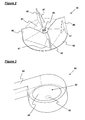
- the impactor 40 is shown most clearly in Figure 2 .
- the impactor 40 comprises a circular support plate 42, a four-sided pyramidal formation 44 formed centrally on the support plate 42, and four impactor blades 46.
- a central, cylindrical bore 48 extends through the centre of the support plate 42 and the pyramidal formation 44.
- the impactor blades 46 extend along the inclined edges of the pyramidal formation 44, and hence radially relative to the circular support plate 42, and each blade 46 is orientated parallel to the axis of rotation of the impactor 40.
- Each blade 46 comprises an outer portion of relatively constant height relative to the circular support plate 42, and an inner portion of gradually reducing height towards the centre of the impactor 40.
- Each blade 46 is also provided with a stay 47, which is generally triangular in form and is formed on the trailing surface of each blade 46.
- Each stay 47 has the form of a plate, and is orientated along the adjacent edge of the pyramidal formation 44.
- the impactor 40 is housed within the impactor housing 50, which is formed in 4mm steel and is shown most clearly in Figure 3 .
- the impactor housing 50 comprises a cylindrical chamber 52, which has one end in which an elliptical inlet 54 is formed. This inlet 54 to the impactor housing 50 is connected to the tubular inlet 30 of the collecting apparatus, as shown clearly in Figure 1 .
- At the other end of the cylindrical chamber 52 is a smaller, central opening 56, through which the impactor shaft 62 extends (see Figure 5 ).
- the impactor housing 50 also includes an outlet 58, which is a box-section conduit extending tangentially from a side wall of the housing 50. This outlet 58 is oriented generally vertically in the apparatus housing 20, and leads to the compactor 70 of the apparatus, as shown in Figure 1 .
- the inlet 54 to the impactor housing 50 is elliptical in shape, with its major axis (Q) arranged parallel to the direction of flow of air and entrained material through the outlet 58 of the housing 50, and perpendicular to the axis of rotation (B) of the impactor 40.
- the impactor 40 is mounted on an impactor shaft 62.
- the impactor shaft 62 is fixed to the impactor 40 at one end, in particular being fixed within the central, cylindrical bore 48 of the impactor 40.
- the other end of the impactor shaft 62 is connected to a drive mechanism (not shown in the Figures).
- the drive mechanism for the impactor shaft 62 and impactor 40 is a power take-off (PTO) mechanism, which is adapted to be run at 600-750 rpm, to produce a rotation of the impactor shaft 62 and impactor 40 at 3500-3700 rpm. This rotational speed has been found to damage domestic plastics recyclable material.
- PTO power take-off
- the vehicle is also provided with an emergency cut-off switch, which is mounted adjacent to the rear inspection hatch (not shown in the Figures).
- the impactor shaft 62 is mounted between its ends to a support plate 64, by means of two bearing units 65.
- the support plate 64 is in turn resiliently mounted to a platform 66 by four resilient mounts 67 formed of rubber, one at each corner of the platform 66.
- the platform 66 is fixed to the apparatus housing 20.
- the impactor mounting 60 also includes a guard 68 mounted at one end of the support plate 64, between the bearing units 65 and the impactor housing 50, with an opening through which the impactor shaft 62 extends.
- the compactor 70 comprises a receiving hopper 72 for receiving recyclable or waste material from the outlet 58 of the impactor housing 50, and a slidable and pivotable compacting member 74 for transferring that material to the storage container 10, and compacting the material therein.
- the storage container 10 also includes a movable end wall 12 that enables the compacted recyclable and waste material to be ejected from the storage container 10, once the apparatus for collecting the recyclable and waste material has been moved, or removed, from the rear of the vehicle.
- the vehicle is driven to a storage container, such as a public storage container for domestic recyclable material (not shown in the Figures).
- a storage container such as a public storage container for domestic recyclable material (not shown in the Figures).
- the flexible outer portion 34 of the inlet 30 is attached to the fixed inner portion 32, and the inlet 30 is then connected by a user to the entrance of the storage container.
- the power take-off (PTO) mechanism to the impactor shaft 62 and impactor 40 is then activated and run by the engine at 600-750 rpm, to produce a rotation of the impactor shaft 62 and impactor 40 at 3500-3700 rpm. This rotation of the impactor 40 generates a suction force at the inlet 30.
- PTO power take-off
- This suction force causes recyclable material to be drawn from the storage container, along the inlet 30, and into the impactor housing 50.
- the recyclable material impacts the impactor 40, which causes damage to the majority of the recyclable material.
- the recyclable material is forced by the impactor 40 through the outlet 58 of the impactor housing 50, and falls into the receiving hopper 72 of the compactor 70.
- the compacting member 74 is operated periodically to transfer the recyclable material within the receiving hopper 72 to the storage container 10 of the vehicle, and compact the recyclable material within the storage container 10. Once the storage container 10 of the vehicle is fully charged, the vehicle is driven to a recyclable material processing plant, where the recyclable material is deposited.
Landscapes
- Engineering & Computer Science (AREA)
- Mechanical Engineering (AREA)
- Refuse Collection And Transfer (AREA)
- Processing Of Solid Wastes (AREA)
Abstract
Apparatus for the collection of recyclable or waste material is disclosed. The apparatus comprises a movable element (40) for drawing ambient air into the apparatus through an inlet (30), in use, thereby creating a suction force that draws the recyclable or waste material into the apparatus through the inlet (30). The apparatus is arranged such that material drawn into the apparatus impacts the movable element (40), and the apparatus further comprises a compactor (70) for reducing the volume occupied by the recyclable or waste material.
Description
- This invention relates to the collection of recyclable or waste material, and in particular to apparatus for the collection of recyclable or waste material, and collection vehicles including such apparatus.
- The generation of waste is a great burden to society and infrastructure, made ever worse by the gradual increase in the world's population. Governments are being required to manage all types of waste, particularly domestic waste, in an efficient and effective manner that is sustainable over the long term. As part of the strategy to tackle this waste burden, many governments have turned to recycling to reduce the amount of waste being sent to landfill sites.
- An important step in the management of waste is its collection. In many countries, a number of schemes are already in place for the collection of recyclable or waste material from public storage containers and/or household storage containers. In particular, community recycling centres are provided in many countries, which contain large, public storage containers allocated for different types of material (such as glass, plastic or paper). In addition, commercial premises are commonly provided with large storage containers for recyclable material. The storage containers themselves may be adapted to be transported to local processing plants. Alternatively, the recyclable material may be transferred manually from these storage containers to conventional collection vehicles, which then transport the recyclable material to local processing plants.
- The problems associated with these schemes for the collection of recyclable material include the difficulty of efficiently collecting and then transporting the recyclable material to the relevant processing plant. In particular, where the storage containers themselves are adapted to be transported to local processing plants, the size of the storage containers is limited, and hence the number of collection trips is increased. Furthermore, where the recyclable material is transferred manually from the storage containers to conventional collection vehicles, which then transport the recyclable material to local processing plants, this manual transfer of material is inefficient and labour intensive.
- There has now been developed apparatus for the collection of recyclable or waste material, which overcomes or substantially mitigates the above-mentioned and/or other disadvantages associated with the prior art.
- According to a first aspect of the invention there is provided apparatus for the collection of recyclable or waste material, the apparatus comprising a movable element for drawing ambient air into the apparatus through an inlet, in use, thereby creating a suction force that draws the recyclable or waste material into the apparatus through the inlet, the apparatus being arranged such that material drawn into the apparatus impacts the movable element, and the apparatus further comprising a compactor for reducing the volume occupied by the recyclable or waste material.
- According to a further aspect of the invention there is provided a method of collecting recyclable or waste material, which method comprises the steps of:
- (a) providing an apparatus as described above;
- (b) operating the movable element to create a suction force that draws the recyclable or waste material into the apparatus through the inlet, such that the material impacts the movable element; and
- (c) operating the compactor to reduce the volume occupied by the recyclable or waste material.
- The apparatus and method according to the invention are advantageous principally because the recyclable or waste material is drawn into the apparatus through the inlet by a suction force generated by the movable element, the recyclable or waste material subsequently impacts the movable element, which preferably damages the material, and finally the volume occupied by the material is reduced by the compactor. The apparatus therefore enables recyclable or waste material to be efficiently collected from a storage container, and then significantly reduced in volume ready for transportation. The present invention therefore removes any need for manually transferring the recyclable or waste material from a storage container to a collection vehicle, and also significantly reduces the volume occupied by the material within the collection vehicle, thereby enabling a greater amount of material to be collected and transported by a particular size of collection vehicle.
- The apparatus according to the invention may be adapted for the collection of any type of recyclable or waste material, such as domestic or commercial waste, but is particularly advantageous in relation to the collection of plastics waste or recyclable material.
- The apparatus is preferably adapted to damage at least some of the material that impacts the movable element, in use, in order to facilitate the reduction of the volume occupied by the recyclable or waste material by the compactor. In particular, the damage that is preferably caused by the movable element, in use, is preferably sufficient to improve the reduction in volume of the recyclable or waste material achievable by the compactor. The damage that is preferably caused by the movable element, in use, may include weakening and/or rupture of at least some of the items of the recyclable or waste material that impacts the movable element.
- The damage that is preferably caused by the movable element, in use, is preferably sufficient to improve the reduction in volume of the recyclable material achievable by the compactor by at least 10%, more preferably by at least 20% and most preferably by at least 30%. In these embodiments, the apparatus is preferably adapted to damage at least 10% of the items of waste or recyclable material drawn through the inlet of the apparatus, more preferably at least 20% and most preferably at least 30%.
- In presently preferred embodiments, the apparatus according to the invention is specifically adapted for the collection of plastics waste or recyclable material, and in particular plastic vessels, eg bottles. In these embodiments, the apparatus is preferably adapted such that the impact with the movable element sufficiently weakens and/or ruptures at least some of the plastic vessels, such that plastic vessels that would otherwise not be compactable by the compactor of the apparatus, for example sealed plastics vessels containing liquid and/or air, are sufficiently damaged by the movable element for those plastics vessels to be compactable by the compactor. For example, the apparatus is preferably adapted such that the impact with the movable element weakens and/or ruptures the areas of the plastics vessels that have the greatest thickness, for example at the base and/or collar of plastic bottles. Most preferably, the plastic vessels remain in one piece.
- It has been found that using conventional apparatus for the collection of plastics recyclable or waste material, approximately 10% of plastics bottles cannot be compacted by a conventional compactor and will withstand a pressure of 40 tonnes without reducing in size. Furthermore, it has been found that a compacted plastics bottle occupies approximately 10% of the volume of a plastics bottle that has not been compacted. Hence, in conventional apparatus for the collection of plastics recyclable or waste material, approximately 50% of the volume of collected plastic bottles is comprised of 10% of the plastic bottles collected.
- The movable element is preferably rotatable, and in particular the movable element preferably comprises a rotatable support and one or more projections mounted thereon. The rotatable support is preferably generally circular or conical in shape, and the one or more projections preferably have the form of blades. In particular, the one or more blades are preferably orientated generally radially on the support. In presently preferred embodiments, the movable element has the form of an impeller, in that it urges air outwardly from its axis of rotation, thereby generating an area of reduced pressure that draws air towards the movable element, along its axis of rotation. This action of the movable element preferably creates a suction force that draws the recyclable or waste material into the apparatus through its inlet, during use.
- In presently preferred embodiments, in order to achieve a desired damage of plastics vessels, as discussed above, the movable element is preferably rotated at a speed of between 1000 and 6000 rpm, more preferably between 2000 and 5000 rpm and most preferably between 3000 and 4000 rpm.
- The movable element is preferably mounted within a housing, and is preferably adapted to transfer air from an inlet of the housing to an outlet of the housing. The inlet of the housing is preferably in communication with the inlet of the apparatus, and the outlet of the housing is preferably in communication with the compactor. The apparatus is preferably therefore arranged to generate air flow from the inlet of the apparatus to the compactor. Furthermore, the apparatus is preferably adapted such that recyclable or waste material is entrained in this airflow, and hence is transferred from the inlet of the apparatus to the compactor.
- The inlet of the apparatus is preferably a tubular conduit, which leads to the movable element. The inlet of the apparatus may be fixed, but preferably includes at least a flexible end portion including an entrance to the inlet, and hence enables the entrance to the inlet to be readily manipulated by a user. In particular, the inlet is preferably adapted to be engaged with, or inserted through, an entrance of a storage container for recyclable or waste material. For convenience, in presently preferred embodiments, the inlet comprises an inner fixed portion that leads to the movable element, and an outer flexible portion that is releasably fixable to the inner fixed portion.
- Where the movable element is rotatable, the housing for the movable element preferably comprises a chamber within which the movable element is disposed, and an inlet through which the material drawn into the apparatus passes immediately before it impacts the movable element. The chamber is preferably generally cylindrical in shape, with the inlet formed in one end of the generally cylindrical chamber. The outlet of the housing is preferably orientated along an axis that is generally orthogonal to the axis of rotation of the movable element, and most preferably generally tangential relative to the movable element, such that the direction of flow of air and entrained material exiting the housing is preferably generally orthogonal to the axis of rotation of the movable element, and preferably also the direction of flow of air and entrained material into the housing through the inlet.
- In presently preferred embodiments, the central axis of the inlet of the housing, along which air and entrained material flows into the housing, in use, is substantially parallel to the axis of rotation of the movable element. In addition, the central axis of the inlet of the housing is preferably off-set from the axis of rotation of the movable element, most preferably in a direction away from the outlet of the housing. It has been found that this feature may reduce the risk that the material drawn into the apparatus will cause an obstruction within the housing. In particular, the distance between the central axis of the inlet of the housing and the outlet of the housing is preferably greater than the distance between the axis of rotation of the movable element and the outlet of the housing. Furthermore, the inlet of the housing preferably has a greater dimension in an axis that is parallel to the direction of flow through the outlet of the housing, relative to its dimension in an axis that is perpendicular to the direction of flow through the outlet of the housing. Most preferably, the inlet of the housing is generally elliptical in shape.
- The movable element is preferably fixedly mounted about a rotatable shaft, which preferably extends through an opening in the housing of the movable element, most preferably in the opposite wall of the housing from the inlet. The rotatable shaft is preferably rotatably mounted to a shaft support, most preferably by at least two bearing units.
- The movable element and its housing are preferably adapted to enable the transfer of recyclable or waste material between the inlet and the outlet of the housing, whilst being sufficiently resistant to material fouling upon the movable element, which would necessitate manual removal of the fouled material. In this regard, where the apparatus is intended for use with domestic recyclable material, and the movable element comprises a rotatable support having a number of blades mounted thereon, it has been found that the preferred number of blades is between three and five blades, and most preferably four blades.
- The movable element is preferably adapted to be sufficiently resistant to the impact of recyclable or waste material, in use, to ensure an acceptable lifetime of the movable element. The movable element is preferably therefore formed of a material of sufficient strength, such as steel.
- Furthermore, where the movable element comprises a rotatable support having a number of blades mounted thereon, it has been found that providing the rotatable support with a raised portion on which an inner portion of each blade is mounted, improves the resistance of the movable element to the impact of recyclable or waste material, in use. The raised portion is preferably conical or pyramidal in form, with the remainder of the rotatable support preferably having the form of a circular plate.
- Most preferably, each blade includes a stay for supporting the blade, which preferably extends between the blade and the rotatable support. The stays are preferably disposed on the trailing surfaces of the blades, with respect to the direction of rotation. Each blade preferably has the form of a plate, which preferably decreases in height relative to the rotatable support, as the blade extends towards the centre of the movable element. Each stay preferably has the form of a plate, and is preferably generally triangular in form.
- The movable element is preferably resiliently mounted relative to the remainder of the apparatus, in order to improve its resistance to the impact of recyclable or waste material, in use. In particular, the movable element is preferably movable away from a rest position, but is biased by the resilient mounting to return to its rest position.
- Where the movable element is fixedly mounted about a rotatable shaft, and the rotatable shaft is rotatably mounted to a shaft support, the shaft support is preferably mounted on one or more resilient members, thereby resiliently mounting the movable element relative to the remainder of the apparatus. In presently preferred embodiments, the shaft support comprises at least two bearing units within which the shaft is mounted, and the at least two bearing units are preferably mounted on a common support. In these embodiments, the common support is preferably mounted on one or more resilient members. The resilient members may be formed of rubber or an elastomeric material, or may have the form of a conventional metal spring.
- The compactor of the apparatus is preferably adapted to receive recyclable or waste material that has been drawn into the apparatus by the movable element, and which has impacted the movable element. The compactor preferably therefore includes a receiving hopper adapted to receive recyclable or waste material following impaction by the movable element. In presently preferred embodiments, the outlet of the housing of the movable element is adapted to direct recyclable or waste material into the receiving hopper of the compactor.
- The compactor is preferably adapted to transfer the recyclable or waste material to a storage container of the apparatus, and hence reduce the volume occupied by the recyclable or waste material within that storage container. The compactor of the apparatus preferably has the form of a conventional compactor for domestic recyclable or waste material. In particular, the compactor preferably comprises a compacting member, such as a slidable plate, adapted to transfer recyclable or waste material from the receiving hopper into the storage container of the apparatus, and compact that material within the storage container. The compacting member is preferably driven by one or more hydraulic rams.
- The apparatus according to the invention is preferably incorporated into a vehicle adapted to collect and transport recyclable or waste material, ie a collection vehicle for recyclable or waste material. Hence, according to a further aspect of the invention, there is provided a collection vehicle for recyclable or waste material comprising apparatus as described above. In these embodiments, the movable element and the compactor are preferably driven by the engine of the vehicle, most preferably using a power take-off (PTO) mechanism.
- The collection vehicle according to the invention may be manufactured in a form that includes the apparatus described above. However, retro-fitting apparatus may be provided to convert conventional collection vehicles that comprise a compactor for reducing the volume occupied by the recyclable or waste material within the collection vehicle.
- Hence, according to a further aspect of the invention, there is provided apparatus adapted to be retro-fitted to a collection vehicle for recyclable or waste material, which collection vehicle comprises a compactor for reducing the volume occupied by the recyclable or waste material within the collection vehicle, the retro-fitted apparatus comprising a movable element for drawing ambient air into the collection vehicle through the inlet, thereby creating a suction force that draws the recyclable or waste material into the collection vehicle through the inlet, the device being arranged such that material drawn into the vehicle impacts the movable element.
- A preferred embodiment of the invention will now be described in greater detail, by way of illustration, with reference to the accompanying drawing, in which:
-
Figure 1 is a schematic side view, showing hidden detail, of an embodiment of a collection vehicle according to the invention; -
Figure 2 is a perspective view, showing hidden detail, of an impactor that forms part of the collection vehicle ofFigure 1 ; -
Figure 3 is a perspective view, showing hidden detail, of an impactor housing that forms part of the collection vehicle ofFigure 1 ; -
Figure 4 is a front view of the impactor housing, showing hidden detail; -
Figure 5 is a side view, showing hidden detail, of the impactor and an impactor shaft on which the impactor is mounted; and -
Figure 6 is a perspective view of an impactor shaft mounting, the impactor and impactor shaft being shown schematically in broken lines. -
Figure 1 shows a collection vehicle according to the invention, which comprises astorage container 10 and rear-mounted apparatus for collecting recyclable or waste material. The apparatus for collecting recyclable or waste material comprises anapparatus housing 20, aninlet 30, an impactor 40, animpactor housing 50, an impactor mounting 60 and acompactor 70. - The
storage container 10, theapparatus housing 20 and thecompactor 70 are of the type found in conventional vehicles for the collection of domestic recyclable or waste material. However, in contrast to their usual arrangement in conventional collection vehicles, theapparatus housing 20 is closed, and hence does not allow ready access by a user to thecompactor 70, for example, save for theinlet 30 and a small inspection hatch (not shown in the Figures). - The
inlet 30 is a tubular conduit, comprising a fixedinner portion 32 formed of steel, and a flexibleouter portion 34 formed of polypropylene, each with a diameter of approximately 0.3m. The fixedinner portion 32 extends from an aperture in a rear wall of theapparatus housing 30, initially at an angle of approximately 45° to horizontal, but terminating in a short vertical end. The flexibleouter portion 34 is releasably connected at one end to the fixedinner portion 32, and at the other end has an entrance through which recyclable or waste material is collected. This entrance to theinlet 30 is adapted to be manipulated by a user, for example to be inserted into, or engaged with, an entrance of a storage container for recyclable or waste material. The flexibleouter portion 34 is adapted to be stowed on the vehicle when not in use. - The impactor 40 is shown most clearly in
Figure 2 . The impactor 40 comprises acircular support plate 42, a four-sidedpyramidal formation 44 formed centrally on thesupport plate 42, and fourimpactor blades 46. In addition, a central,cylindrical bore 48 extends through the centre of thesupport plate 42 and thepyramidal formation 44. - The
impactor blades 46 extend along the inclined edges of thepyramidal formation 44, and hence radially relative to thecircular support plate 42, and eachblade 46 is orientated parallel to the axis of rotation of the impactor 40. Eachblade 46 comprises an outer portion of relatively constant height relative to thecircular support plate 42, and an inner portion of gradually reducing height towards the centre of the impactor 40. Eachblade 46 is also provided with astay 47, which is generally triangular in form and is formed on the trailing surface of eachblade 46. Eachstay 47 has the form of a plate, and is orientated along the adjacent edge of thepyramidal formation 44. - The impactor 40 is housed within the
impactor housing 50, which is formed in 4mm steel and is shown most clearly inFigure 3 . In particular, theimpactor housing 50 comprises acylindrical chamber 52, which has one end in which anelliptical inlet 54 is formed. Thisinlet 54 to theimpactor housing 50 is connected to thetubular inlet 30 of the collecting apparatus, as shown clearly inFigure 1 . At the other end of thecylindrical chamber 52 is a smaller,central opening 56, through which theimpactor shaft 62 extends (seeFigure 5 ). Theimpactor housing 50 also includes anoutlet 58, which is a box-section conduit extending tangentially from a side wall of thehousing 50. Thisoutlet 58 is oriented generally vertically in theapparatus housing 20, and leads to thecompactor 70 of the apparatus, as shown inFigure 1 . - As shown most clearly in
Figure 4 , theinlet 54 to theimpactor housing 50 is elliptical in shape, with its major axis (Q) arranged parallel to the direction of flow of air and entrained material through theoutlet 58 of thehousing 50, and perpendicular to the axis of rotation (B) of the impactor 40. In addition, the centre - (A) of the
inlet 54 to theimpactor housing 50 is off-set from the axis of rotation (B) of the impactor 40, in a direction perpendicularly away from theoutlet 58 of thehousing 50. It has been found that this arrangement of theinlet 54 to theimpactor housing 50 reduces the risk that material entering thehousing 50 causes an obstruction during use. - As shown in
Figure 5 , the impactor 40 is mounted on animpactor shaft 62. Theimpactor shaft 62 is fixed to the impactor 40 at one end, in particular being fixed within the central, cylindrical bore 48 of the impactor 40. The other end of theimpactor shaft 62 is connected to a drive mechanism (not shown in the Figures). The drive mechanism for theimpactor shaft 62 andimpactor 40 is a power take-off (PTO) mechanism, which is adapted to be run at 600-750 rpm, to produce a rotation of theimpactor shaft 62 andimpactor 40 at 3500-3700 rpm. This rotational speed has been found to damage domestic plastics recyclable material. The vehicle is also provided with an emergency cut-off switch, which is mounted adjacent to the rear inspection hatch (not shown in the Figures). - As shown most clearly in
Figure 6 , theimpactor shaft 62 is mounted between its ends to asupport plate 64, by means of two bearingunits 65. Thesupport plate 64 is in turn resiliently mounted to aplatform 66 by fourresilient mounts 67 formed of rubber, one at each corner of theplatform 66. Theplatform 66 is fixed to theapparatus housing 20. The impactor mounting 60 also includes aguard 68 mounted at one end of thesupport plate 64, between the bearingunits 65 and theimpactor housing 50, with an opening through which theimpactor shaft 62 extends. - Referring now to
Figure 1 , thecompactor 70 comprises a receivinghopper 72 for receiving recyclable or waste material from theoutlet 58 of theimpactor housing 50, and a slidable andpivotable compacting member 74 for transferring that material to thestorage container 10, and compacting the material therein. Thestorage container 10 also includes amovable end wall 12 that enables the compacted recyclable and waste material to be ejected from thestorage container 10, once the apparatus for collecting the recyclable and waste material has been moved, or removed, from the rear of the vehicle. - In use, the vehicle is driven to a storage container, such as a public storage container for domestic recyclable material (not shown in the Figures). Once situated adjacent to the storage container, the flexible
outer portion 34 of theinlet 30 is attached to the fixedinner portion 32, and theinlet 30 is then connected by a user to the entrance of the storage container. The power take-off (PTO) mechanism to theimpactor shaft 62 andimpactor 40 is then activated and run by the engine at 600-750 rpm, to produce a rotation of theimpactor shaft 62 andimpactor 40 at 3500-3700 rpm. This rotation of the impactor 40 generates a suction force at theinlet 30. - This suction force causes recyclable material to be drawn from the storage container, along the
inlet 30, and into theimpactor housing 50. In theimpactor housing 50, the recyclable material impacts the impactor 40, which causes damage to the majority of the recyclable material. The recyclable material is forced by the impactor 40 through theoutlet 58 of theimpactor housing 50, and falls into the receivinghopper 72 of thecompactor 70. - The compacting
member 74 is operated periodically to transfer the recyclable material within the receivinghopper 72 to thestorage container 10 of the vehicle, and compact the recyclable material within thestorage container 10. Once thestorage container 10 of the vehicle is fully charged, the vehicle is driven to a recyclable material processing plant, where the recyclable material is deposited.
Claims (15)
- Apparatus for the collection of recyclable or waste material, the apparatus comprising a movable element (40) for drawing ambient air into the apparatus through an inlet (30), in use, thereby creating a suction force that draws the recyclable or waste material into the apparatus through the inlet (30), the apparatus being arranged such that material drawn into the apparatus impacts the movable element (40), and the apparatus further comprising a compactor (70) for reducing the volume occupied by the recyclable or waste material.
- Apparatus adapted to be retro-fitted to a collection vehicle for recyclable or waste material, which collection vehicle comprises a compactor (70) for reducing the volume occupied by the recyclable or waste material within the collection vehicle, the retro-fitted apparatus comprising a movable element (40) for drawing ambient air into the collection vehicle through the inlet (30), thereby creating a suction force that draws the recyclable or waste material into the collection vehicle through the inlet (30), the device being arranged such that material drawn into the vehicle impacts the movable element (40).
- Apparatus as claimed in Claim 1 or Claim 2, wherein the movable element (40) is resiliently mounted relative to the remainder of the apparatus.
- Apparatus as claimed in any preceding claim, wherein the movable element (40) comprises a rotatable support (42) having a number of blades (46) mounted thereon, and the rotatable support (42) is provided with a raised portion (44) on which an inner portion of each blade (46) is mounted.
- Apparatus as claimed in any preceding claim, wherein the movable element (40) is rotatable and mounted within a housing (50), the housing (50) comprising a chamber (52) within which the movable element (40) is disposed, and an inlet (30) through which the material drawn into the apparatus passes immediately before it impacts the movable element (40), the movable element (40) being adapted to transfer air from the inlet (30) of the housing (50) to an outlet (58) of the housing (50), the outlet (58) of the housing (50) being orientated along an axis that is generally orthogonal to the axis of rotation of the movable element (40), and the central axis of the inlet (30) of the housing (50) being substantially parallel to the axis of rotation of the movable element (40).
- Apparatus as claimed in Claim 5, wherein the central axis of the inlet (30) of the housing (50) is off-set from the axis of rotation of the movable element (40), in a direction away from the outlet (58) of the housing (50).
- Apparatus as claimed in any preceding claim, wherein the inlet (30) of the apparatus is adapted to be engaged with, or inserted through, an entrance of a storage container for recyclable or waste material, such that the apparatus is adapted to collect recyclable or waste material from the storage container.
- A method of collecting recyclable or waste material, which method comprises the steps of:(a) providing an apparatus as claimed in any preceding claim;(b) operating the movable element (40) to create a suction force that draws the recyclable or waste material into the apparatus through the inlet (30), such that the material impacts the movable element (40); and(c) operating the compactor (70) to reduce the volume occupied by the recyclable or waste material.
- A method as claimed in Claim 8, wherein the recyclable or waste material is collected from a storage container.
- A method as claimed in Claim 9, wherein the method includes the step of engaging the inlet (30) with, or inserting the inlet (30) through, an entrance of a storage container for recyclable material.
- A method as claimed in Claim 9 or Claim 10, wherein the storage container is a public storage container for domestic recyclable material.
- A method as claimed in any one of Claims 8 to 11, wherein the recyclable or waste material being collected is plastics waste or recyclable material.
- A method as claimed in Claim 12, wherein the plastics recyclable or waste material being collected includes plastics vessels, and at least some of the plastic vessels are weakened and/or ruptured by impact with the movable element (40), such that at least some plastic vessels that would otherwise not be compactable by the compactor (70) of the apparatus are sufficiently damaged by the movable element (40) for those plastics vessels to be compactable by the compactor (70).
- A method as claimed in Claim 13, wherein the plastics vessels remain in one piece.
- A method as claimed in any one of Claims 8 to 14, wherein the movable element (40) is rotated at a speed of between 1000 and 6000 rpm.
Applications Claiming Priority (1)
| Application Number | Priority Date | Filing Date | Title |
|---|---|---|---|
| GB0903039A GB2461604B (en) | 2009-02-24 | 2009-02-24 | Improvements relating to the collection of recyclable or waste material |
Publications (1)
| Publication Number | Publication Date |
|---|---|
| EP2221259A1 true EP2221259A1 (en) | 2010-08-25 |
Family
ID=40565568
Family Applications (1)
| Application Number | Title | Priority Date | Filing Date |
|---|---|---|---|
| EP10154343A Withdrawn EP2221259A1 (en) | 2009-02-24 | 2010-02-23 | Apparatus and method of collecting recyclable or waste material |
Country Status (4)
| Country | Link |
|---|---|
| US (1) | US8640300B2 (en) |
| EP (1) | EP2221259A1 (en) |
| CR (1) | CR11294A (en) |
| GB (1) | GB2461604B (en) |
Families Citing this family (4)
| Publication number | Priority date | Publication date | Assignee | Title |
|---|---|---|---|---|
| GB2461604B (en) | 2009-02-24 | 2010-07-21 | Recresco Ltd | Improvements relating to the collection of recyclable or waste material |
| US20160058260A1 (en) * | 2014-04-19 | 2016-03-03 | Wayne Eric Boone | Power Transfer In An Industrial Carpet Cleaner |
| ES1166233Y (en) * | 2016-09-15 | 2016-12-27 | Urban Refuse Dev Slu | Pneumatic waste collection device |
| IT201700051212A1 (en) * | 2017-05-11 | 2018-11-11 | P T C S R L | Waste collection vehicle |
Citations (7)
| Publication number | Priority date | Publication date | Assignee | Title |
|---|---|---|---|---|
| US4200950A (en) * | 1978-04-21 | 1980-05-06 | Coverley Roger D | Large area cleaning system |
| FR2697510A1 (en) * | 1992-10-29 | 1994-05-06 | Gouetard Dropsy | Waste aspirator, crusher and loader - comprises turbine with aspirating crushing blades, container loading platform and openings for waste passage |
| FR2707963A1 (en) * | 1993-07-22 | 1995-01-27 | Vbs | Device for collecting and compacting plastic bottles |
| DE4331191A1 (en) * | 1993-09-14 | 1995-03-16 | Josef Soellner | Motor vehicle for the transportation of solid material collected in collection containers |
| US5718017A (en) * | 1996-03-08 | 1998-02-17 | Pavlick; Curtis | Waste collector |
| EP1125868A1 (en) * | 2000-02-17 | 2001-08-22 | Van Loen Techniek B.V. | Domestic refuse collection vehicle |
| GB2461604A (en) * | 2009-02-24 | 2010-01-13 | Recresco Ltd | Apparatus for the collection of recyclable or waste material |
Family Cites Families (15)
| Publication number | Priority date | Publication date | Assignee | Title |
|---|---|---|---|---|
| GB314255A (en) | 1928-08-03 | 1929-06-27 | Karrier Motors Ltd | Improvements in or relating to vehicles for collecting and transporting refuse |
| US3407432A (en) * | 1965-09-27 | 1968-10-29 | Finn Equipment Company | Debris collector |
| US3588179A (en) * | 1968-01-17 | 1971-06-28 | Oscar D Gifford | Power mower clipping-collecting attachment-collecting trailer therefor |
| US3665545A (en) * | 1970-06-04 | 1972-05-30 | William Beekman | Apparatus for collecting debris |
| CH517865A (en) * | 1970-06-20 | 1972-01-15 | Schmidt Alfred Ing Fa | Attachment for work vehicle for picking up mown grass, leaves or the like from road verges |
| US3995754A (en) * | 1974-02-27 | 1976-12-07 | Lawrence Peska Associates, Inc. | Garbage vacuum compactor device |
| US4019219A (en) * | 1975-10-03 | 1977-04-26 | The Raymond Lee Organization, Inc. | Trash compactor apparatus |
| AU6413580A (en) * | 1979-11-17 | 1981-05-21 | Hestair Eagle Ltd. | Suction operated refuse collecting apparatus |
| GB2241524A (en) | 1990-03-03 | 1991-09-04 | Andrew Marc Edwards | Refuse collecting apparatus |
| US5317783A (en) * | 1992-09-25 | 1994-06-07 | Haybuster Manufacturing Inc. | Vacuum trailer |
| GB9303749D0 (en) * | 1993-02-24 | 1993-04-14 | Baumung R Ind Ltd | Crushing apparatus |
| US6003195A (en) * | 1997-12-02 | 1999-12-21 | Woodland Power Products, Inc. | Vacuum generation device |
| KR20020085162A (en) | 2001-05-07 | 2002-11-16 | 주식회사 지엠테크 | Impeller of a refuse cart |
| GB0127719D0 (en) | 2001-11-19 | 2002-01-09 | Chapman Pauline L | Waste glass storage |
| US20060059652A1 (en) * | 2004-09-23 | 2006-03-23 | Alan Vry | Debris collector |
-
2009
- 2009-02-24 GB GB0903039A patent/GB2461604B/en active Active
-
2010
- 2010-02-23 CR CR11294A patent/CR11294A/en not_active Application Discontinuation
- 2010-02-23 US US12/710,564 patent/US8640300B2/en not_active Expired - Fee Related
- 2010-02-23 EP EP10154343A patent/EP2221259A1/en not_active Withdrawn
Patent Citations (7)
| Publication number | Priority date | Publication date | Assignee | Title |
|---|---|---|---|---|
| US4200950A (en) * | 1978-04-21 | 1980-05-06 | Coverley Roger D | Large area cleaning system |
| FR2697510A1 (en) * | 1992-10-29 | 1994-05-06 | Gouetard Dropsy | Waste aspirator, crusher and loader - comprises turbine with aspirating crushing blades, container loading platform and openings for waste passage |
| FR2707963A1 (en) * | 1993-07-22 | 1995-01-27 | Vbs | Device for collecting and compacting plastic bottles |
| DE4331191A1 (en) * | 1993-09-14 | 1995-03-16 | Josef Soellner | Motor vehicle for the transportation of solid material collected in collection containers |
| US5718017A (en) * | 1996-03-08 | 1998-02-17 | Pavlick; Curtis | Waste collector |
| EP1125868A1 (en) * | 2000-02-17 | 2001-08-22 | Van Loen Techniek B.V. | Domestic refuse collection vehicle |
| GB2461604A (en) * | 2009-02-24 | 2010-01-13 | Recresco Ltd | Apparatus for the collection of recyclable or waste material |
Also Published As
| Publication number | Publication date |
|---|---|
| GB2461604B (en) | 2010-07-21 |
| GB2461604A (en) | 2010-01-13 |
| GB2461604A8 (en) | 2010-03-10 |
| GB0903039D0 (en) | 2009-04-08 |
| US8640300B2 (en) | 2014-02-04 |
| US20100215444A1 (en) | 2010-08-26 |
| CR11294A (en) | 2010-05-26 |
Similar Documents
| Publication | Publication Date | Title |
|---|---|---|
| US8640300B2 (en) | Collection of recyclable or waste material | |
| EP0220936A2 (en) | Materials processing unit | |
| US5680994A (en) | Mill for grinding garbage or the like | |
| CN110424314A (en) | Road worthy leaf collecting cart | |
| US20140312035A1 (en) | Means, method and process of condensing discarded recyclable cups inside each other | |
| CN111056181A (en) | Garbage can recycling device with function of automatically dumping garbage | |
| CN209720587U (en) | A kind of categorized consumer waste recyclable device | |
| CN209905586U (en) | Automatic classification dustbin | |
| CN222551384U (en) | A negative pressure separator for garbage screening | |
| CN218506708U (en) | Household full-automatic garbage classification box | |
| CN108894468A (en) | A kind of high-building construction refuse disposal shaft and method of construction | |
| CN201519594U (en) | Chopper with auxiliary waste container | |
| CN210654718U (en) | Stirring type storage bin for storing and throwing household garbage | |
| CN214440916U (en) | Movable garbage winnowing machine | |
| CN208121660U (en) | A kind of intelligent garbage cleaning classified collection device | |
| CA3171839A1 (en) | Depackaging system with spray and dilution system to increase plastic and reject cleanliness | |
| CN210654682U (en) | Garbage can for classifying recoverable garbage | |
| CN211467601U (en) | Garbage treatment device for municipal administration | |
| CN214326081U (en) | Garbage recycling device | |
| CN106076835B (en) | Light rubbish grid sub-pressure selective equipment | |
| CN112893119A (en) | Movable garbage winnowing machine | |
| CN206253205U (en) | A kind of rubbish crushes dust arrester | |
| CN221852994U (en) | Urban garbage classification and transportation equipment | |
| CN212916553U (en) | An energy-saving garbage recycling device | |
| CN221419471U (en) | Environment-friendly dustbin with food classification collects |
Legal Events
| Date | Code | Title | Description |
|---|---|---|---|
| PUAI | Public reference made under article 153(3) epc to a published international application that has entered the european phase |
Free format text: ORIGINAL CODE: 0009012 |
|
| AK | Designated contracting states |
Kind code of ref document: A1 Designated state(s): AT BE BG CH CY CZ DE DK EE ES FI FR GB GR HR HU IE IS IT LI LT LU LV MC MK MT NL NO PL PT RO SE SI SK SM TR |
|
| 17P | Request for examination filed |
Effective date: 20110202 |
|
| 17Q | First examination report despatched |
Effective date: 20110624 |
|
| STAA | Information on the status of an ep patent application or granted ep patent |
Free format text: STATUS: THE APPLICATION IS DEEMED TO BE WITHDRAWN |
|
| 18D | Application deemed to be withdrawn |
Effective date: 20130903 |