EP2221173A1 - Electroluminescent film compound with a protective film laminate - Google Patents
Electroluminescent film compound with a protective film laminate Download PDFInfo
- Publication number
- EP2221173A1 EP2221173A1 EP08020616A EP08020616A EP2221173A1 EP 2221173 A1 EP2221173 A1 EP 2221173A1 EP 08020616 A EP08020616 A EP 08020616A EP 08020616 A EP08020616 A EP 08020616A EP 2221173 A1 EP2221173 A1 EP 2221173A1
- Authority
- EP
- European Patent Office
- Prior art keywords
- layers
- layer
- protective film
- film laminate
- electroluminescent
- Prior art date
- Legal status (The legal status is an assumption and is not a legal conclusion. Google has not performed a legal analysis and makes no representation as to the accuracy of the status listed.)
- Ceased
Links
Images
Classifications
-
- B—PERFORMING OPERATIONS; TRANSPORTING
- B32—LAYERED PRODUCTS
- B32B—LAYERED PRODUCTS, i.e. PRODUCTS BUILT-UP OF STRATA OF FLAT OR NON-FLAT, e.g. CELLULAR OR HONEYCOMB, FORM
- B32B27/00—Layered products comprising a layer of synthetic resin
- B32B27/06—Layered products comprising a layer of synthetic resin as the main or only constituent of a layer, which is next to another layer of the same or of a different material
-
- B—PERFORMING OPERATIONS; TRANSPORTING
- B32—LAYERED PRODUCTS
- B32B—LAYERED PRODUCTS, i.e. PRODUCTS BUILT-UP OF STRATA OF FLAT OR NON-FLAT, e.g. CELLULAR OR HONEYCOMB, FORM
- B32B7/00—Layered products characterised by the relation between layers; Layered products characterised by the relative orientation of features between layers, or by the relative values of a measurable parameter between layers, i.e. products comprising layers having different physical, chemical or physicochemical properties; Layered products characterised by the interconnection of layers
- B32B7/04—Interconnection of layers
- B32B7/06—Interconnection of layers permitting easy separation
-
- B—PERFORMING OPERATIONS; TRANSPORTING
- B32—LAYERED PRODUCTS
- B32B—LAYERED PRODUCTS, i.e. PRODUCTS BUILT-UP OF STRATA OF FLAT OR NON-FLAT, e.g. CELLULAR OR HONEYCOMB, FORM
- B32B7/00—Layered products characterised by the relation between layers; Layered products characterised by the relative orientation of features between layers, or by the relative values of a measurable parameter between layers, i.e. products comprising layers having different physical, chemical or physicochemical properties; Layered products characterised by the interconnection of layers
- B32B7/04—Interconnection of layers
- B32B7/12—Interconnection of layers using interposed adhesives or interposed materials with bonding properties
Definitions
- the present invention relates to an electroluminescent composite film with a protective film laminate, a process for its preparation, and their use as lighting on a motor vehicle.
- the illumination is preferably achieved by electroluminescent films, which are fastened with a single-sided adhesive tape on the racing vehicle, for example on the door (s) and / or the hood.
- the adhesive tape is preferably guided completely around the edge of the electroluminescent film, which adheres one part of the tape to the film and another part to the surface on which the film is to be fastened.
- electroluminescent films offer the advantage that they are self-luminous and can thus illuminate characters including graphics and lettering without the need for prior illumination by an external light source.
- An object of the present invention was therefore to provide an electroluminescent film composite (EL film composite) which can be cleaned quickly and effectively, that is, which can be quickly and effectively rid of dirt.
- EL film composite electroluminescent film composite
- the protective film laminate (a) comprises at least one (1) layer.
- the protective film laminate (a) comprises at least 2 layers, more preferably the protective film laminate (a) comprises at least 5 layers, most preferably the protective film laminate (a) comprises at least 10 layers, especially at least 25 layers.
- a maximum number of layers of the protective film laminate (a) is in the range between 40 and 50 layers. Depending on the application, however, a number of 1, 2, 3, 4, 5, 6, 7, 8, 9, 10, 11 or 12 layers may be useful. A low number of layers is particularly advantageous if the EL element foreseeable only a few times, for example, one, two or three or four times, must be cleaned or should.
- the protective film laminate (a) preferably covers the EL element (c) over the entire surface, whereby the entire surface of the EL element can be protected, and protrudes flat over this at its edges.
- the adhesive layer (b) on the underside of the protective film laminate (a) fixes it to the EL element. Through the parts of the protective laminate (a), which protrude over the EL element surface, the entire EL film composite is attached by means of the adhesive layer (b) on a substrate.
- the EL film composite can be applied to any surface.
- the substrate is a surface of metal, plastic, glass, wood and / or concrete, which in turn may be coated, for example with a paint, a paint, a plastic film, paper or cardboard;
- a paint, a paint, a plastic film, paper or cardboard are also possible. Examples of such a surface are doors, windows, bonnets of motor vehicles,
- Advertising columns Billboards, shop windows, walls of public transport stops, etc.
- the film composite as a whole can be produced for example by methods known to those skilled in the art, such as hot or cold laminating, placing the protective film laminate (a) including adhesive layer (b) on the EL element (c) or vice versa with the aid of pick & place machines or laminating ,
- Electroluminescence refers to the direct luminescence excitation of luminescent pigments (also called luminous substances or luminophors) through an alternating electric field.
- Information carrier advertising or transparency can serve for decorative purposes, known in the art.
- US2007 / 223211A1 For example, it is known to backlit the interior sides of a menu with at least one EL element to allow restaurant guests to read the menu even in subdued light. US2007 / 223211A1 also discloses the electronics, switchgear and power supply associated with the EL application. Among other things, the electronics make it possible to produce color changes of the EL element.
- WO2006100164A1 discloses the construction of an EL element with a substrate corresponding to substrate (ca) of polycarbonate and a certain water vapor permeability of the protective layer, corresponding to (cc), in FIG WO2006100164A1 Called protective laminate.
- Such EL elements can be almost freely deformable three-dimensional.
- the German patent application DE 10 2006 059 203 A1 discloses such an EL element.
- the element In order for this film element is three-dimensionally deformable, the element must have a specific layer structure. The deformation of the film element can then be carried out by high-pressure isostatic deformation. In the context of the present invention, the use of such three-dimensionally deformable EL elements is particularly preferred.
- the EL element may be configured such that the side of the substrate provided with the EL device is illuminated, or that an at least partially transparent substrate is illuminated by a back-mounted EL device. Furthermore, the illumination can also radiate to both sides, if the substrate is at least partially transparent.
- a protective film laminate (a) suitable for the present invention is made US 5,592,698 A . US 6,388,813 B1 . US2002 / 0109922A1 . US 6,536,045 B1 and US2003 / 0066118A1 known.
- the EL element provided according to the invention may have further layers.
- the substrate itself is electrically conductive, it may or may not be provided with an additional insulating layer to which the EL device is then applied.
- the EL element may have one or more reflective layers.
- the reflection layer preferably comprises glass beads, in particular hollow glass beads.
- the diameter of the glass beads can be changed within wide limits. Thus, they can have a size d 50 of generally 5 ⁇ m to 3 mm, preferably 10 to 200 ⁇ m, particularly preferably 20 to 100 ⁇ m.
- the hollow glass beads are preferably embedded in a binder.
- one or more at least partially transparent graphically designed layers can be arranged on the substrate and / or the substrate and the EL arrangement.
- the EL element provided according to the invention with inverse layer structure can have further layers.
- the substrate itself is electrically conductive, it may or may not be provided with an additional insulating layer to which the EL device is then applied.
- the EL element may have one or more reflective layers.
- one or more at least partially transparent graphically designed layers can be arranged on the EL arrangement, its base and / or on the protective film laminate (a).
- the one or more insulation layer (s) (cbb) and / or (cbd) both in the conventional structure and in the inverse structure can or can be omitted in particular if the component (cbc) has a layer thickness which short-circuits the two Electrode components (cba) and (cbe) prevented.
- the electrodes (cba) and (cbe) have electrical connections, which are preferably guided to a side edge of the film element according to the invention and contacted there by contacting aids with a current source.
- Suitable contacting aids are, for example, crimping, clamping, electrically conductive adhesive, rivets, screws and other means known to those skilled in the art.
- the control of the EL element can be carried out in a conventional manner known to the expert.
- the activation of the resulting EL element is effected by a capacitive energy transfer.
- the EL element according to the invention is operated by means of alternating current.
- the alternating current is preferably generated by means of an EL-DC / AC inverter.
- the inverter is conventionally mounted together with control electronics on a printed circuit board.
- the power supply can be done for example by battery (s), rechargeable accumulator (s) or by supply by an external power source.
- a power supply may be provided by the battery (s) and / or rechargeable battery (s).
- the EL element used according to the invention has a first at least partially transparent electrode, front electrode (cba), and a second back electrode (cbe).
- the expression "at least partially transparent” means an electrode which is constructed from a material which has a transmission of visible light of generally more than 60%, preferably more than 70%, particularly preferably more than 80%, especially more than 90%.
- the back electrode (cbe) of the EL arrangement which may be provided for example on the surface of the substrate, does not necessarily have to be transparent or opaque.
- Suitable electrical conductive materials for the electrodes are known per se to those skilled in the art. Basically, when producing thick-film EL elements with AC excitation (thick-film AC-EL elements), there are several types of electrodes. On the one hand, these are sputtered or vapor deposited indium-tin-oxide electrodes (indium-tin-oxides, ITO) in vacuum on plastic films. They are very thin (some 100 ⁇ ) and offer the advantage of high transparency with a relatively low surface resistance (about 60 to 600 ⁇ ).
- ITO indium-tin-oxides
- printing pastes with ITO or ATO (antimony tin oxides, antimony tin oxide) or intrinsically conductive transparent polymer pastes can be used, from which surface electrodes are produced by screen printing. At a thickness of about 5 to 20 microns such electrodes offer only lower transparency at high surface resistance (up to 50 k ⁇ ). They can be applied in virtually any structure, even on structured surfaces. Furthermore, they offer a relatively good laminatability.
- Non-ITO screen printing layers (the term "non-ITO” encompasses all screen printing layers which are not based on indium-tin-oxide (ITO)), ie intrinsically conductive polymer layers with usually nanoscale electrically conductive pigments, for example the ATO screen-printing pastes polymer polyethylene-dioxythiophene with the designations 7162E or 7164 from DuPont, intrinsically conductive polymer systems such as Orgacon ® system from Agfa, the Clevios ® poly (3,4-ethylenedioxythiophene) system from HC Starck GmbH, which (as an organic metal PEDTconductive ) system of Ormecon, conductive coating or ink systems of Panipol OY and optionally with highly flexible binders, for example based on PU (polyurethanes), PMMA (polymethyl methacrylate), PVA (polyvinyl alcohol), modified polyaniline, can be used.
- PU polyurethanes
- PMMA poly
- electrically conductive polymer films are polyanilines, polythiophenes, polyacetylenes, polypyrroles ( Handbook of Conducting Polymers, 1986 ) with and without metal oxide filling.
- a printing paste for producing the at least partially transparent electrode preference is given to 10 to 90% by weight, preferably 20 to 80% by weight, particularly preferably 30 to 65% by weight, based in each case on the total weight of Clevios P, Clevios P AG, Clevios P HCV4, Clevios P HS, Clevios PH 500, Clevios PH 510 or any mixtures thereof.
- solvents dimethylsulfoxide (DMSO), N, N-dimethylformamide, N, N-dimethylacetamide, ethylene glycol, glycerol, sorbitol, methanol, ethanol, isopropanol, N-propanol, acetone, methyl ethyl ketone, dimethylaminoethanol, water or mixtures of two or three or more of said solvents can be used.
- the amount of solvent can vary widely in the printing paste. Thus, in one formulation of a paste 55 to 60 wt .-% solvent may be included, while in another formulation, about 35 to 45 wt .-% of a solvent mixture of two or more solvents are used.
- Neo Rez R986, Dynol 604 and / or mixtures of two or more of these substances may be included.
- the amount thereof is 0.1 to 5.0 wt .-%, preferably 0.3 to 2.5 wt .-%, based on the total weight of the printing paste.
- binders which may be present in the formulation are UD-85, Bayhydrol PR340 / 1, Bayhydrol PR135 or any mixtures thereof, preferably in amounts of from about 0.5 to 10% by weight, preferably from 3 to 5% by weight.
- the polyurethane dispersions used, which form the binder for the conductive layer after the layer has been dried, are preferably aqueous polyurethane dispersions.
- Particularly preferred formulations of printing pastes according to the invention for producing the at least partially transparent electrode (cba) comprise:
- the ready-to-use formulations mentioned below can also be used according to the invention as ready-made, commercially available printing pastes: the Orgacon EL-P1000, EL-P3000, EL-P5000 or EL-P6000 series from Agfa, preferably the EL-P3000 and EL-P6000 series (especially for deformable applications).
- tin oxide (NESA) pastes are also conceivable as corresponding electrode material.
- the electrically conductive materials described above may also be applied to a substrate.
- a carrier material for example, offer transparent glasses and thermoplastic films. Corresponding carrier materials are described in more detail below. Within the scope of the present invention, one or two carrier substrates may be used
- Electrode materials can be applied, for example, by means of screen printing, knife coating, spraying, spraying, brushing onto corresponding carrier materials (substrates), preferably subsequently drying at low temperatures of, for example, 80 to 120 ° C.
- the application of the electrically conductive coating takes place by means of vacuum or pyrolytically.
- the electrically conductive coating is particularly preferably a thin and largely transparent layer which is produced by means of vacuum or pyrolytically produced metallic or metal oxide and which preferably has a sheet resistance of 5 m ⁇ to 3000 ⁇ / square, particularly preferably a sheet resistance of 0.1 to 1000 ⁇ / sq. very particularly preferably has 5 to 30 ⁇ / square, and in another preferred embodiment has a daylight transmittance of at least greater than 60% (> 60 to 100%) and in particular greater than 76% (> 76 to 100%).
- electrically conductive glass can also be used as the electrode.
- a particular preferred type of electrically conductive and highly transparent glass, in particular float glass, are pyrolytically produced layers which have a high surface hardness and whose surface electrical resistivity can be adjusted in a very wide range, generally from a few milliohms to 3000 ⁇ / square.
- Such pyrolytically coated glasses can be well deformed and have a good scratch resistance, in particular scratches do not lead to an electrical interruption of the electrically conductive surface layer, but only to a mostly slight increase in surface resistance.
- pyrolytically produced conductive surface layers are so strongly diffused into the surface by the temperature treatment and anchored in the surface, that in a subsequent application of material an extremely high adhesion to the glass substrate is given, which is also very advantageous for the present invention.
- coatings have a good homogeneity, ie a low scattering of the surface resistance value over large surfaces. This feature also provides an advantage to the present invention.
- Electrically conductive and highly transparent thin layers can be produced on a glass substrate, which is preferably used according to the invention, much more efficiently and cost-effectively than on polymeric substrates such as PET or PMMA or PC.
- the electrical surface resistance is on glass coatings on average by a factor of 10 cheaper than on a polymeric film with comparable transparency, for example, 3 to 10 ohms / square in glass layers compared with 30 to 100 ⁇ / square on PET films.
- the back electrode (cbe) is - as in the case of the at least partially transparent electrode (cba) - a planar electrode, which, however, need not be transparent or at least partially transparent. This is generally applied to the insulating layer, if present. If no insulation layer is present, the back electrode is applied to the layer containing at least one excitable by an electric field luminous substance. In an alternative embodiment, the back electrode is applied to the at least partially transparent substrate (ca).
- the back electrode is generally constructed of inorganic or organic based electrically conductive materials such as metals such as silver, preferably using those materials that are not damaged when using the high pressure isostatic forming process to produce the three-dimensionally deformed EL element.
- Suitable electrodes are also in particular polymeric electrically conductive coatings. In this case, the coatings already mentioned above with regard to the at least partially transparent electrode can be used. In addition, it is possible to use those polymeric, electrically conductive coatings which are known to the person skilled in the art and which are not at least partially transparent.
- Suitable materials of the back electrode are thus preferably selected from the group consisting of metals such as silver, carbon, ITO screen printing layers, ATO screen printing layers, non-ITO screen printing layers, ie intrinsically conductive polymeric systems with usually nanoscale electrically conductive pigments, for example ATO dyes.
- the formulation of the print paste for the back electrode may correspond to that of the partially transparent electrode.
- a printing paste for the production of the back electrode 30 to 90% by weight, preferably 40 to 80% by weight, particularly preferably 50 to 70% by weight, based in each case on the total weight of the printing paste, of the conductive polymer Clevios P, Clevios PH, Clevios P AG, Clevios P HCV4, Clevios P HS, Clevios PH, Clevios PH 500, Clevios PH 510 or any mixtures thereof.
- solvents dimethyl sulfoxide (DMSO), N, N-dimethylformamide, N, N-dimethylacetamide, ethylene glycol, glycerol, sorbitol, methanol, ethanol, Isopropanol, N-propanol, Acton, methyl ethyl ketone, dimethylaminoethanol, water or mixtures of two or three or more of these solvents may be used.
- the amount of solvent used can vary widely. Thus, in a formulation according to the invention, one paste may contain from 55 to 60% by weight of solvent, while in another formulation according to the invention about 40% by weight of a solvent mixture of three solvents may be used.
- Neo Rez R986, Dynol 604 or mixtures of two or more of these substances may preferably be contained in an amount of 0.7 to 1.2 wt .-%.
- binders for example, 0.5 to 1.5 wt .-% UD-85, Bayhydrol PR340 / 1, Bayhydrol PR135 or any mixtures thereof may be included.
- the back electrode may be filled with graphite. This can be achieved by adding graphite to the formulations described above.
- the ready-to-use formulations mentioned below can also be used according to the invention as ready-made, commercially available printing pastes: the Orgacon EL-P1000, EL-P3000, EL-P5000 or EL-P6000 series from Agfa, prefers the EL-P3000 and EL-P6000 series (for deformable applications). Again, graphite can be added.
- the printing pastes of the Orgacon EL-P4000 series can be used. Both can be mixed together in any ratio.
- Orgacon EL-P4010 and EL-4020 already contain graphite.
- graphite pastes can also be used as back electrode, for example graphite pastes from Acheson, in particular Electrodag 965 SS or Electrodag 6017 SS.
- a particularly preferred formulation according to the invention of a printing paste for producing the back electrode BE comprises:
- bus bars (listed above under component (cbf)) can be used, in particular in the case of semiconducting LEP or OLED systems in which relatively large currents flow.
- Very good electrically conductive tracks are produced in the manner of a cross. In this way, for example, a large area is divided into four small areas.
- the voltage drop in the central region of a luminous surface is substantially reduced and reduces the uniformity of the luminance or the drop in brightness in the middle of a luminous field.
- the electrical connections can be made, for example, using electrically conductive and stovable pastes with tin, zinc, silver, palladium, aluminum and other suitable conductive metals or combinations and mixtures or alloys thereof.
- the electrically conductive contact strips are generally applied to the electrically conductive and at least partially transparent thin coatings by means of screen printing, brush application, inkjet, doctor blade, roller, by spraying or by Dispensierlves or comparable application methods known in the art and then generally in an oven thermally treated, so that usually attached laterally along a Sub substrate edge strips can be contacted by soldering, terminals or plug electrically conductive.
- conductive adhesive pastes based on silver, palladium, copper or gold filled polymer adhesive are preferably used. It is also possible to apply self-adhesive electrically conductive strips, for example, of tinned copper foil with an adhesive that is electrically conductive in the z-direction by pressing.
- the adhesive layer is generally uniformly pressed with a surface pressure of some N / cm 2 , and depending on the design, values of 0.013 ohm / cm 2 are obtained (eg Conductive Copper Foil Tape VE 1691 from D & M International, A-8451 Heimschuh). or 0.005 ohms (eg Type 1183 from 3M Electrical Products Division, Austin, Texas USA, according to MIL-STD-200 Method 307 maintained at 5 psi / 3.4 N / cm 2 measured over 1 sq.in. 0.001 ohms (eg Type 1345 from 3M) or 0.003 ohms (eg Type 3202 from Holland Shielding Systems BV).
- N / cm 2 eg Conductive Copper Foil Tape VE 1691 from D & M International, A-8451 Heimschuh.
- 0.005 ohms eg Type 1183 from 3M Electrical Products Division, Austin, Texas USA, according to MIL-STD-200 Method 30
- the inventive El element optionally has one or more dielectric layer (s) as component (s) (cbb) and / or (cbd), which in the case of component (cbb) between the front electrode (cba) and the EL layer component (cbc) is provided and in the case of component (cbd) between the back electrode component (cbe) and the electroluminescent layer component (cbc) is provided.
- Corresponding dielectric layers are known to the person skilled in the art. Corresponding layers often have high dielectric powders, such as barium titanate, which are preferably dispersed in fluorine-containing plastics or in cyan-based resins. Examples of particularly suitable particles are barium titanate particles in the range of preferably 1.0 to 2.0 ⁇ m. These can give a relative dielectric constant of up to 100 at a high degree of filling.
- the dielectric layer has a thickness of generally 1 to 50 ⁇ m, preferably 2 to 40 ⁇ m, more preferably 5 to 25 ⁇ m, especially 8 to 15 ⁇ m.
- the EL element can also additionally have a further dielectric layer, which are arranged one above the other and together improve the insulation effect or which is interrupted by a floating electrode layer.
- the use of a second dielectric layer may depend on the quality and pinhole freedom of the first dielectric layer.
- inorganic insulating materials are used, which are known to those skilled in the literature, for example: BaTiO 3 , SrTiO 3 , KNbO 3 , PbTiO 3 , LaTaO 3 , LiNbO 3 , GeTe, Mg 2 TiO 4 , Bi 2 (TiO 3 ) 3 , NiTiO 3 , CaTiO 3 , ZnTiO 3 , Zn 2 TiO 4 , BaSnO 3 , Bi (SnO 3 ) 3 , CaSnO 3 , PbSnO 3 , MgSnO 3 , SrSnO 3 , ZnSnO 3 , BaZrO 3 , CaZrO 3 , PbZrO 3 , MgZrO 3 , SrZrO 3 , ZnZrO 3 or mixtures of two or more of these fillers.
- Preferred fillers according to the invention are BaTiO 3 or PbZrO 3 or mixtures thereof, preferably in quantities of from 5 to 80% by weight, preferably from 10 to 75% by weight, particularly preferably from 40 to 70% by weight, based in each case on the total weight of the paste, in the paste for the preparation of the insulating layer.
- Binders for this layer may be one-component or preferably two-component polyurethane systems, preferably Bayer MaterialScience AG, again particularly preferably Desmodur and Desmophen or the coating raw materials of the Lupranate, Lupranol, Pluracol or Lupraphen series from BASF AG; Degussa AG (Evonik), preferably Vestanat, again particularly preferred Vestanat T and B; or the Dow Chemical Company, again preferably Vorastar; be used.
- highly flexible binders for example those based on PMMA, PVA, in particular Mowiol and Poval from Kuraray Europe GmbH or Kuraray Specialties Europe GmbH or Polyviol from Wacker AG, or PVB, in particular Mowital from Kuraray Europe GmbH or Kuraray Specialties Europe GmbH (B 20 H, B 30 T, B 30 H, B 30 HH, B 45 H, B 60 T, B 60 H, B 60 HH, B 75 H) or Pioloform, in particular Pioloform BR18, BM18 or BT18, of Wacker AG, are used.
- solvents for example, ethyl acetate, butyl acetate, 1-Methoxypropylacetat-2, toluene, xylene, Solvesso 100, Shellsol A or mixtures of two or more of these solvents can be used.
- PVB polyvinyl acetate
- solvents for example, ethyl acetate, butyl acetate, 1-Methoxypropylacetat-2, toluene, xylene, Solvesso 100, Shellsol A or mixtures of two or more of these solvents can be used.
- PVB binder
- Dowanol methoxypropyl acetate, methyl acetate, ethyl acetate, butyl acetate, butoxyl, glycolic acid
- additives such as leveling agents and rheology additives can be added to improve the properties. Examples of flow control agents are Additol XL480 in butoxyl in a mixing ratio of 40:60 to 60:40.
- BYK 410, BYK 411, BYK 430, BYK 431 or any mixtures thereof may be present, for example.
- compositions of a printing paste for producing the insulating layer as component (f) and / or (g) comprise:
- the EL element (c) according to the invention comprises an EL layer as component (cbc).
- the at least one electroluminescent (EL) layer (cbc) is generally arranged between the first at least partially transparent electrode (cba) and a dielectric layer (cbd).
- the EL layer can be arranged directly after the dielectric layer or, if appropriate, one or more further layers can be arranged between the dielectric layer and the EL layer.
- the EL layer is preferably arranged immediately after the dielectric layer.
- the at least one EL layer (cbc) may be arranged on the entire inner surface of the first at least partially transparent electrode (cba) or on one or more partial surfaces of the first at least partially transparent electrode.
- the partial surfaces generally have a spacing of 0.5 to 10.0 mm, preferably 1 to 5 mm from each other.
- the EL layer (cbc) is generally composed of a binder matrix having dispersed therein homogeneously EL pigments.
- the binder matrix is generally selected such that a good adhesion bond is provided on the electrode layer (or the dielectric layer possibly applied thereon.)
- PVB or PU-based systems are used further additives are present in the binder matrix, such as color-converting organic and / or inorganic systems, color additives for a day and night light effect and / or reflective and / or light-absorbing effect pigments such as aluminum flakes or glass flakes or mica platelets.
- the EL pigments used in the EL layer (cbc) generally have a thickness of 1 to 50 ⁇ m, preferably 5 to 25 ⁇ m.
- the at least one EL layer (cbc) is an AC thick film powder EL (AC-P-EL) light structure.
- AC-P-EL AC thick film powder EL
- Thick film AC-EL systems have been well-known since Destriau 1947 and are usually applied by screen printing on ITO-PET films. Since zinc sulfide electroluminophores have a very high degradation during operation and especially at higher temperatures and a steam environment, microencapsulated EL luminophores (pigments) are generally used today for long-lived thick-film AC-EL elements. However, it is also possible to use in the EL element according to the invention ⁇ non-microencapsulated pigments, as further described below.
- EL elements are understood to mean thick-film EL systems which are operated by means of alternating voltage at normative 100 V and 400 Hertz and thus emit a so-called cold light of a few cd / m 2 up to a few 100 cd / m 2 animals.
- EL screen pastes are generally used.
- Such EL screen-printing pastes are generally based on inorganic substances. Suitable substances are, for example, high-purity ZnS, CdS, Zn x Cd 1-x S compounds of groups II and IV of the Periodic Table of the Elements, with ZnS being particularly preferably used.
- the above-mentioned substances can be doped or activated and optionally further be coactivated.
- For doping for example copper and / or manganese are used. Coactivation takes place, for example, with chlorine, bromine, iodine and aluminum.
- the content of alkali and rare earth metals is generally very low in the abovementioned substances, if they are present at all.
- Very particular preference is given to using ZnS, which is preferably doped or activated with copper and / or manganese and is preferably co-activated with chlorine, bromine, iodine and / or aluminum.
- Common EL emission colors are yellow, green, green-blue, blue-green and white, whereby the emission color white or red can be obtained by mixtures of suitable EL luminophores or by color conversion.
- the color conversion can generally take place in the form of a converting layer and / or the addition of corresponding dyes and pigments in the polymeric binder of the screen printing inks or the polymeric matrix in which the EL pigments are incorporated.
- the screen printing matrix used for producing the EL layer (cbc) are provided with translucent, color-filtering or color-converting dyes and / or pigments. In this way, an emission color white or a day-night lighting effect can be generated.
- pigments are used in the EL layer which have an emission in the blue wavelength range from 420 to 480 nm and are provided with a color-converting microencapsulation. In this way, the color white can be emitted.
- AC-P-EL pigments which have an emission in the blue wavelength range of 420 to 480 nm.
- the AC-P-EL screen printing matrix preferably has wavelength-controlling inorganic fine particles based on europium (II) activated alkaline earth metal orthosilicate phosphors such as (Ba, Sr, Ca) 2 SiO 4 : Eu 2+ or YAG phosphors such as Y 3 Al 5 O 12 : Ce 3+ or Tb 3 Al 5 O 12 : Ce 3+ or Sr 2 GaS 4 : Eu 2+ or SrS: Eu 2+ or (Y, Lu, Gd, Tb) 3 (Al, Sc, Ga ) 5 O 12 : Ce 3+ or (Zn, Ca, Sr) (S, Se): Eu 2+ .
- a white emission can be achieved.
- the aforementioned EL luminophores can be microencapsulated. Due to the inorganic microencapsulation technology good half-lives can be achieved. As an example, the EL screen printing system Luxprint ® for EL of the company EI du Pont de Nemours and Companies mentioned. Organic microencapsulation technologies and film-wrap laminates based on the various thermoplastic films are also generally suitable, but have proven to be expensive and not significantly extended in life.
- Suitable zinc sulfide microencapsulated EL phosphors are sold by Osram Sylvania, Inc. Towanda under the trade name GlacierGLO TM Standard, High Brite and Long Life and the Durel Division of Rogers Corporation, under the trade names 1PHS001 ® High-Efficiency Green Encapsulated EL Phosphor , 1PHS002 ® high-Efficiency Blue-Green EL Encapsulated phosphorus, 1PHS003® Long-Life Blue Encapsulated EL phosphor, 1PHS004 ® Long-Life Orange Encapsulated EL phosphor offered.
- the average particle diameters of the microencapsulated pigments suitable in the EL layer are generally 15 to 60 ⁇ m, preferably 20 to 35 ⁇ m.
- Non-microencapsulated fine-grained EL pigments preferably with a long service life, can also be used in the EL layer (cbc).
- Suitable non-microencapsulated fine-grained zinc sulfide EL luminophores are, for example, in US 6,248,261 and in WO 01/34723 disclosed. These preferably have a cubic crystal structure.
- the non-microencapsulated pigments preferably have average particle diameters of from 1 to 30 .mu.m, particularly preferably from 3 to 25 .mu.m, very particularly preferably from 5 to 20 .mu.m.
- Specially non-microencapsulated EL pigments can be used with smaller pigment dimensions down to less than 10 ⁇ m. As a result, the transparency of the glass element can be increased.
- suitable screen printing inks can be incorporated with unencapsulated pigments, preferably taking into account the specific hygroscopic properties of the pigments, preferably the ZnS pigments.
- This binders are generally used, on the one hand have a good adhesion to so-called ITO layers (indium-tin oxide) or intrinsically conductive polymeric transparent layers, and also have good insulating effect, enhance the dielectric and thus improve the dielectric strength at high electric field strengths cause and additionally in the cured state have a good water vapor barrier and additionally protect the phosphorus pigments and extend lifetime extend.
- pigments which are not microencapsulated are used in the AC-P-EL luminescent layer.
- the half-lives of the suitable pigments in the EL layer (cbc), ie the time in which the initial brightness of the EL element according to the invention has fallen to half, are generally at 100 or 80 volts and 400 hertz 400 to a maximum of 5000 hours but usually not more than 1000 to 3500 hours.
- the brightness values (EL emission) are generally 1 to 200 cd / m 2 , preferably 3 to 100 cd / m 2 , and are particularly preferably in the range from 1 to 40 cd / m 2 for large luminous areas.
- the pigments present in the EL layer (cbc) have such a small average particle diameter, or such a low degree of filling in the EL layer (cbc), or the individual EL layers (cbc) geometrically made so small, or the distance of the individual EL layers (cbc) is chosen so large, so that the EL element (c) is designed as non-electrically activated lighting structure as at least partially transparent or a review is guaranteed.
- Suitable pigment particle diameters, fill levels, dimensions of the luminous elements and distances of the luminous elements are mentioned above.
- the layer contains the abovementioned optionally doped ZnS crystals, preferably microencapsulated as described above, preferably in an amount of from 40 to 90% by weight, preferably from 50 to 80% by weight, particularly preferably from 55 to 70% by weight. , in each case based on the weight of the paste.
- binders one- and preferably two-component polyurethanes can be used.
- highly flexible materials from Bayer MaterialScience AG are preferred, for example the lacquer raw materials of the desmophen and desmodur series, preferably desmophen and desmodur, or the lacquer raw materials of the Lupranate, Lupranol, Pluracol or Lupraphen series from BASF AG.
- solvents ethoxypropyl acetate, ethyl acetate, butyl acetate, methoxypropyl acetate, acetone, methyl ethyl ketone, methyl isobutyl ketone, cyclohexanone, toluene, xylene, solvent naphtha 100 or any mixtures of two or more of these solvents in amounts of preferably 1 to 50 wt .-%, preferably 2 to 30 Wt .-%, particularly preferably 5 to 15 wt .-%, each based on the total paste mass used.
- polymer binders such as PVB may further include solvents such as methanol, ethanol, propanol, isopropanol, diacetone alcohol, benzyl alcohol, 1-methoxy-2-propanol, butyl glycol, methoxybutanol, dowanol, methoxypropyl acetate, methyl acetate, ethyl acetate, butyl acetate, butoxyl, glycolic acid n-buty
- b more preferably 3 to 10 wt .-% are added.
- 0.1 to 2 wt .-% additives to improve the flow behavior and the course may be included.
- flow control agents are Additol XL480 in butoxyl in a mixing ratio of 40:60 to 60:40. 0.01 to 10 wt .-%, preferably 0.05 to 5 wt .-%, particularly preferably 0.1 to 2 wt .-%, each based on the total paste mass, rheology additives which contain the settling behavior can be included as further additives of pigments and fillers in the paste, for example BYK 410, BYK 411, BYK 430, BYK 431 or any mixtures thereof.
- Formulations of printing pastes which are particularly preferred according to the invention for producing the EL layer as component (cbc) include:
- the electroluminescent element may comprise a protective layer, component (cc), in order to avoid destruction of the electroluminescent element or the optionally present graphical representations.
- Suitable materials of the protective layer (cc) are known to the person skilled in the art.
- Suitable protective layers (cc) are, for example, high-temperature-resistant protective lacquers, such as conformal lacquers containing polycarbonates and binders.
- An example of such a protective lacquer is Noriphan HTR ® by Proell, Weissenburg.
- the protective layer (cc) may also be formulated on the basis of flexible polymers such as polyurethanes, PMMA, PVA, PVB. Polyurethanes from Bayer MaterialScience AG can be used for this purpose.
- This formulation can also be provided with fillers. Suitable for this purpose are all fillers known to the person skilled in the art, for example based on inorganic metal oxides such as TiO 2 , ZnO, lithopone, etc. with a degree of filling of 10 to 80% by weight of the printing paste, preferably from 20 to 70%, particularly preferably from 40 to 60%.
- the formulations may contain leveling agents as well as rheology additives. As a solvent, for example.
- compositions of the protective layer (cc) according to the invention as lacquer include, for example:
- the protective layer (cc) may also be formed as a protective film (cc). Suitable films for this are known in the art.
- the electroluminescent element (c) may have on one or both sides of the respective electrodes substrates (ca), such as glasses, plastic films or the like.
- At least the substrate (ca), which is in contact with the transparent electrode (cba), is designed on the inside graphically translucent and opaque covering.
- An opaque covering design is understood to be a large-area electroluminescent region which is opacified by a high-resolution graphic design and / or is designed to be translucent, for example in the sense of red-green-blue translucent, for signal purposes.
- the substrate which is in contact with the transparent electrode (cba) is a film which is cold-stretchable under glass transition temperature Tg. This gives rise to the possibility of deforming the resulting EL element (c) three-dimensionally.
- the substrate (ca) which is in contact with the back electrode (cbe) is a film which is also cold-stretchable under the glass transition temperature Tg. This gives rise to the possibility of deforming the resulting EL element (c) three-dimensionally.
- the EL element (c) is thus three-dimensionally deformable, wherein the radii of curvature may be less than 2 mm, preferably less than 1 mm.
- the deformation angle can be greater than 60 °, preferably greater than 75 °, particularly preferably greater than 90, in particular greater than 105 °.
- the EL element (c) is three-dimensionally deformable and, in particular, cold stretchable under glass transition temperature Tg and thus obtains a precisely shaped three-dimensional shape.
- the three-dimensionally deformed EL element (c) can be formed in an injection molding tool on at least one side with a thermoplastic material.
- the layers of the protective film laminate (a) consist of a material selected from the group consisting of polyester, polyvinyl chloride, polyurethane, polycarbonate, polymethyl methacrylate or a polyolefin, preferably polyethylene or polypropylene.
- the layers of the protective film laminate (a) consist of a polyethylene terephthalate (PET), in particular of a biaxially oriented polyethylene terephthalate (BOPET), as it is available, for example, under the trade name Mylar from DuPont.
- PET polyethylene terephthalate
- BOPET biaxially oriented polyethylene terephthalate
- the layers of the protective film laminate (a) each consist of the same material.
- a clear adhesive layer is arranged between the layers of the protective film laminate (a).
- the adhesive layer preferably comprises a material selected from the group consisting of pressure-sensitive adhesive polymers based on acrylic acid and / or methacrylic acid and their esters, polyacrylates, isobutylene, polyvinyl acetate, ethylene-vinyl acetate, natural and / or synthetic rubbers, for example acrylonitrile Butadiene rubber, butyl rubber or neoprene rubber, styrene-diene copolymers such as styrene-butadiene block copolymers and hot melt adhesives, or which is prepared based on pressure-sensitive adhesive silicone polymers or polysiloxanes.
- the adhesive consists of clear water-based pressure-sensitive polymers based on acrylic acid and / or methacrylic acid. Clear here means that the adhesive layer has a transmission of visible light of generally more than 90%, preferably more than 95%, particularly preferably more than 99%, especially more than 99.5%.
- the adhesive layer is applied over the entire surface or not over the entire surface in relation to the substrate.
- the adhesive layer (b) with which the protective film laminate (a) is applied both on the EL element and on the substrate.
- the adhesive layer (b) has the same composition and type as the adhesive layers between the films of the protective film laminate (a).
- a different composition and type of adhesive layer (b) can also be selected. It is also possible that the adhesive layer (b) in the areas in which it rests on the EL film, a different composition and type, as in the areas where it rests on the ground.
- the layers of the protective film laminate (a) preferably have a strip on at least one side of the layers. Again preferably, this strip is not bonded to an adhesive layer on the underlying layer of the protective film laminate (a).
- the strip allows easy and safe removal of a layer of the protective film laminate (a) by tearing.
- the adhesion of the lowermost layer of the protective film laminate (a) with that of the EL element (c) is stronger than the adhesion between the individual layers of the protective film laminate (a), respectively.
- the adhesion of the lowermost layer of the protective film laminate (a) with that of the EL element (c) may also be equal to the adhesion between the individual layers of the protective film laminate (a).
- the layers (ca), (cb) and (cc) are designed only in part with respect to the protective film laminate (a).
- Both the layers of the protective film laminate (a) and the adhesive layers including the adhesive layer (b) preferably have a refractive index at a temperature of 20 ° C in the range of 1.40 to 1.52, the difference in refractive indices between the layers of the Protective film laminate (a) and the adhesive layers including the adhesive layer (b) is not more than 0.2. In this way it is achieved that the intensity of the radiation of the EL element is not reduced.
- the layers of the protective film laminate (a) preferably have a thickness in the range from 0.01 to 0.3 mm, preferably in the range from 0.012 to 0.2 mm, particularly preferably in the range from 0.02 to 0.1 mm.
- Another object of the present invention is the use of an EL film composite as lighting on a motor vehicle.
- the position of the at least one EL film composite on the motor vehicle can be chosen arbitrarily.
- a motor vehicle is understood to mean that a motor vehicle is provided with the at least one EL film composite, so that the EL film composite attracts the observer and is recognized by the observer, that is to say to him in the eye, in particular when the EL foil composite lights up.
- the size of the at least one EL film composite on the motor vehicle can be chosen arbitrarily. Both parameters, that is, position and size, however, are preferably chosen so that the aforementioned object of the present invention is achieved, that is, the EL film composite is sufficiently large and positioned at that position of the motor vehicle, so that the motor vehicle Observer is noticeable and easily recognized by this.
- the individual EL film composites may have an identical or different design, that is, in particular size, shape and color.
- the individual EL foil composites can be attached to any position on the motor vehicle. In particular, it is possible for individual EL film composites to overlap.
- the at least one EL film composite can be attached in an appealing and / or striking external appearance in order to give the motor vehicle as a whole a pleasant and or eye-catching appearance.
- the EL film composite according to the invention is advantageously used everywhere where EL elements can and should be used, and where rapid cleaning of the EL element is desired.
- Another object of the present invention is therefore the use of an EL film composite as lighting on house walls, advertising columns, billboards, shop windows, walls of public transport stops, especially for advertising purposes, as Decoration lighting, as emergency lighting in the road, in the aerospace and military.
- the EL film composite has more than one EL element (c), which can emit light of the same or different color, and which can be electronically controlled separately, so that an animated luminous image can be achieved.
Abstract
Description
Die vorliegende Erfindung betrifft einen elektrolumineszierenden Folienverbund mit einem Schutzfolienlaminat, ein Verfahren zu dessen Herstellung, sowie deren Verwendung als Beleuchtung auf einem Kraftfahrzeug.The present invention relates to an electroluminescent composite film with a protective film laminate, a process for its preparation, and their use as lighting on a motor vehicle.
Jeder Teilnehmer eines Automobilrennens, wie zum Beispiel dem 24-Stunden-Rennen von LeMans, muss funktionstüchtige leuchtende Startnummern am entsprechenden Rennenfahrzeug besitzen. Die Beleuchtung wird vorzugsweise durch elektrolumineszierende Folien erreicht, die mit einem einseitig klebenden Klebeband am Rennfahrzeug, beispielsweise an der oder den Tür(en) und/oder der Motorhaube befestigt werden. Das Klebeband wird dazu vorzugsweise vollumfänglich derart um den Rand der elektrolumineszierenden Folie geführt, das ein Teil des Bandes auf der Folie und ein anderer Teil auf der Oberfläche haftet, auf der die Folie befestigt werden soll.Any participant in an automobile race, such as the LeMans 24 Hours, must have functioning luminous start numbers on the corresponding race car. The illumination is preferably achieved by electroluminescent films, which are fastened with a single-sided adhesive tape on the racing vehicle, for example on the door (s) and / or the hood. To this end, the adhesive tape is preferably guided completely around the edge of the electroluminescent film, which adheres one part of the tape to the film and another part to the surface on which the film is to be fastened.
Ebenfalls ist es erforderlich, die Werbungen der jeweiligen Sponsoren und deren Logos auch bei Dunkelheit sichtbar zu machen.It is also necessary to make the advertisements of the respective sponsors and their logos visible even in the dark.
Eine Möglichkeit, Zeichen bei Dunkelheit sichtbar zu machen, besteht darin Reflexionsfolien zu verwenden, die das Licht zurückwerfen, sofern sie angestrahlt werden. Daraus ergibt sich allerdings der offensichtliche Nachteil, dass ohne vorherige Beleuchtung mit einem Strahler keine Reflektion der entsprechenden Zeichen stattfinden kann.One way to make signs visible in the dark is to use reflective films that reflect the light when illuminated. However, this has the obvious disadvantage that without prior illumination with a radiator no reflection of the corresponding characters can take place.
Gegenüber Reflexionsfolien bieten elektrolumineszierende Folien den Vorteil, dass diese selbstleuchtend sind und somit Zeichen inklusive Grafiken und Schriftzügen beleuchtet darstellen können, ohne dass eine vorherige Beleuchtung durch eine externe Lichtquelle notwendig war.Compared with reflective films, electroluminescent films offer the advantage that they are self-luminous and can thus illuminate characters including graphics and lettering without the need for prior illumination by an external light source.
Bei Automobilrennen, die unter extremen Witterungsbedingungen und auf verschmutztem Gelände stattfinden, ergibt sich als eine weitere Anforderung an elektrolumineszierende Folien, dass diese auch gereinigt werden müssen, um Zeichen wieder sichtbar zu machen. Da diese Reinigung aber möglichst schnell und effektiv erfolgen soll, um den Rennverlauf nicht zu verzögern bzw. zu beeinträchtigen, ist es erforderlich, den elektrolumineszierenden Folienverbund so zu gestalten, dass dessen schnelle und effektive Reinigung ermöglicht ist.In automotive races that take place in extreme weather conditions and on dirt, another requirement of electroluminescent films is that they must also be cleaned to make characters visible again. However, since this cleaning should take place as quickly and effectively as possible so as not to delay or impair the course of the race, it is necessary to design the electroluminescent film composite in such a way that its rapid and effective cleaning is made possible.
Eine Aufgabe der vorliegenden Erfindung bestand daher darin, einen elektrolumineszierenden Folienverbund (EL-Folienverbund) zur Verfügung zu stellen, der sich schnell und effektiv reinigen lässt, das heißt der sich schnell und effektiv von Schmutz befreien lässt.An object of the present invention was therefore to provide an electroluminescent film composite (EL film composite) which can be cleaned quickly and effectively, that is, which can be quickly and effectively rid of dirt.
Die vorstehend genannte Aufgabe wurde durch das Zurverfügungstellen eines EL-Folienverbundes gelöst, der eine Schichtenfolge aufweist, umfassend:
- ein Schutzfolienlaminat (a)
- mit einer Klebstoffschicht (b),
- und ein Elektrolumineszenzelement (EL-Element) (c), umfassend
- > ein zumindest teilweise transparentes Substrat (ca),
- > ein mindestens einer auf dem Substrat aufgebrachten EL-Anordnung (cb), und
- > eine Schutzschicht oder Schutzfolie (cc).
- a protective film laminate (a)
- with an adhesive layer (b),
- and an electroluminescent element (EL element) (c) comprising
- > an at least partially transparent substrate (ca),
- > at least one EL device (cb) applied to the substrate, and
- > a protective layer or protective film (cc).
Dabei umfasst das Schutzfolienlaminat (a) wenigstens eine (1) Schicht. Vorzugsweise umfasst das Schutzfolienlaminat (a) wenigstens 2 Schichten, besonders bevorzugt umfasst das Schutzfolienlaminat (a) wenigstens 5 Schichten, ganz besonders bevorzugt umfasst das Schutzfolienlaminat (a) wenigstens 10 Schichten, insbesondere wenigstens 25 Schichten. Bevorzugt ist eine maximale Anzahl von Schichten des Schutzfolienlaminats (a) im Bereich zwischen 40 und 50 Schichten. Je nach Anwendung kann aber auch eine Anzahl von 1, 2, 3, 4, 5, 6, 7, 8, 9, 10, 11 oder 12 Schichten sinnvoll sein. Eine geringe Schichtzahl ist insbesondere dann vorteilhaft, wenn das EL-Element absehbar nur wenige Male, beispielsweise ein-, zwei- oder drei- oder viermal, gereinigt werden muss oder soll.The protective film laminate (a) comprises at least one (1) layer. Preferably, the protective film laminate (a) comprises at least 2 layers, more preferably the protective film laminate (a) comprises at least 5 layers, most preferably the protective film laminate (a) comprises at least 10 layers, especially at least 25 layers. Preferably, a maximum number of layers of the protective film laminate (a) is in the range between 40 and 50 layers. Depending on the application, however, a number of 1, 2, 3, 4, 5, 6, 7, 8, 9, 10, 11 or 12 layers may be useful. A low number of layers is particularly advantageous if the EL element foreseeable only a few times, for example, one, two or three or four times, must be cleaned or should.
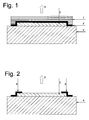
Das Schutzfolienlaminat (a) bedeckt vorzugsweise des EL-Element (c) vollflächig, wodurch die gesamte Oberfläche des EL-Elements geschützt werden kann, und ragt flächig über dieses an dessen Rändern hinaus. Durch die Klebstoffschicht (b) an der Unterseite des Schutzfolienlaminats (a) wird dieses auf dem EL-Element befestigt. Durch die Teile des Schutzlaminats (a), die über das EL-Element flächig hinausragen, wird der gesamte EL-Folienverbund mittels der Klebstoffschicht (b) auf einem Untergrund befestigt.The protective film laminate (a) preferably covers the EL element (c) over the entire surface, whereby the entire surface of the EL element can be protected, and protrudes flat over this at its edges. The adhesive layer (b) on the underside of the protective film laminate (a) fixes it to the EL element. Through the parts of the protective laminate (a), which protrude over the EL element surface, the entire EL film composite is attached by means of the adhesive layer (b) on a substrate.
Der EL-Folienverbund kann auf einem beliebigen Untergrund aufgebracht werden. Vorzugsweise handelt es sich bei dem Untergrund um eine Oberfläche aus Metall, Kunststoff, Glas, Holz und/oder Beton, die ihrerseits noch beschichtet sein kann, beispielsweise mit einem Lack, einem Farbaufstrich, einer Kunststofffolie, Papier oder Pappe; jedoch sind andere Materialien für den Untergrund ebenfalls möglich. Beispiele für eine solche Oberfläche sind Türen, Fenster, Motorhauben von Kraftfahrzeugen,The EL film composite can be applied to any surface. Preferably, the substrate is a surface of metal, plastic, glass, wood and / or concrete, which in turn may be coated, for example with a paint, a paint, a plastic film, paper or cardboard; However, other materials for the substrate are also possible. Examples of such a surface are doors, windows, bonnets of motor vehicles,
Werbesäulen, Plakatwände, Schaufenster, Wandungen von Haltestellen des öffentlichen Nahverkehrs etc.Advertising columns, billboards, shop windows, walls of public transport stops, etc.
Der EL-Folienverbund kann im Wesentlichen auf zwei Arten auf einem Untergrund zur Verfügung gestellt werden:
- 1 Zuerst wird das EL-Element (c) auf den Untergrund aufgebracht, beispielweise gelegt, mit der Hand gehalten und/oder geklebt. Danach wird das Schutzfolienlaminat (a) mit der Klebstoffschicht (b) auf das EL-Element und den Untergrund aufgebracht. Das Schutzfolienlaminat (a) kann vor der Aufbringung auf der Klebstoffseite vorzugsweise herstellerseitig mit einer leicht entfernbaren Schutzlage für die Klebstoffschicht (b) versehen sein, wobei die Schutzlage erst vor der Anbringung des Schutzfolienlaminats (a) entfernt wird.
- 2 Der EL-Folienverbund wird als Ganzes vorbereitet, vorzugsweise vorproduziert, und als Ganzes auf den Untergrund aufgebracht. Der EL-Folienverbund kann vor der Aufbringung auf der EL-Elementseite vorzugsweise herstellerseitig mit einer leicht entfernbaren Schutzlage für die Klebstoffschicht (b), die über das EL-Element (c) hinausragt, versehen sein, wobei die Schutzlage erst vor der Anbringung des Schutzfolienlaminats (a) entfernt wird. Die Schutzlage kann im Wesentlichen nur die Bereiche bedecken, in denen die Klebstoffschicht (b) über das EL-Element (c) hinausragt oder vorzugsweise im Wesentlichen die gesamte Rückseite des EL-Folienverbunds.
- 1 First, the EL element (c) is applied to the substrate, for example laid, held by hand and / or glued. Thereafter, the protective film laminate (a) with the adhesive layer (b) is applied to the EL element and the substrate. The protective film laminate (a) may preferably be provided by the manufacturer with an easily removable protective layer for the adhesive layer (b) prior to application to the adhesive side, wherein the protective layer is removed only before the attachment of the protective film laminate (a).
- 2 The EL film composite is prepared as a whole, preferably pre-produced, and applied as a whole to the substrate. The EL film composite may preferably be provided by the manufacturer with an easily removable protective layer for the adhesive layer (b) which projects beyond the EL element (c) prior to application to the EL element side, the protective layer only before the application of the protective film laminate (a) is removed. The protective layer can substantially only cover the areas in which the adhesive layer (b) projects beyond the EL element (c) or preferably substantially the entire back side of the EL film composite.
Der Folienverbund als Ganzes kann beispielsweise durch dem Fachmann bekannte Verfahren wie Heiß - oder Kaltlaminieren, Aufsetzen des Schutzfolienlaminats (a) einschließlich Klebeschicht (b) auf das EL-Element (c) oder umgekehrt mit Hilfe von Pick & Place-Automaten oder Kaschieren hergestellt werden.The film composite as a whole can be produced for example by methods known to those skilled in the art, such as hot or cold laminating, placing the protective film laminate (a) including adhesive layer (b) on the EL element (c) or vice versa with the aid of pick & place machines or laminating ,
Unter Elektrolumineszenz (EL) versteht man die direkte Lumineszenzanregung von Leuchtpigmenten (auch Leuchtsubtanzen oder Luminophore genannt) durch ein elektrisches Wechselfeld.Electroluminescence (EL) refers to the direct luminescence excitation of luminescent pigments (also called luminous substances or luminophors) through an alternating electric field.
Die EL-Technologie hat in jüngster Zeit zunehmend an Bedeutung gewonnen. Sie ermöglicht dieEL technology has recently gained in importance. It allows the
Realisierung beinahe beliebig großer, blend- und schattenfreier, homogener Leuchtflächen. Dabei sind Leistungsaufnahme und Bautiefe (in der Größenordnung eines Millimeters und darunter) äußerst gering. Zu den typischen Anwendungen gehört neben der Hintergrundbeleuchtung von Flüssigkristall-Displays auch die Hinterleuchtung von transparenten Filmen, welche mit Beschriftungen und/oder Bildmotiven versehen sind. Somit sind transparente EL-Elemente, wie beispielsweise EL-Leuchtplatten auf der Basis von Glas oder transparentem Kunststoff, die beispielsweise alsRealization of almost any size, glare-free and shadow-free, homogeneous illuminated areas. Power consumption and depth (on the order of one millimeter and below) are extremely low. In addition to the backlighting of liquid crystal displays, the typical applications include the backlighting of transparent films which are provided with captions and / or image motifs. Thus, transparent EL elements, such as EL light panels based on glass or transparent plastic, for example as
Informationsträger, Werbetransparente oder zu dekorativen Zwecken dienen können, aus dem Stand der Technik bekannt.Information carrier, advertising or transparency can serve for decorative purposes, known in the art.
Aus
Auch können solche EL-Elemente nahezu frei dreidimensional verformbar sein. Die deutsche Patentanmeldung
Das EL-Element kann derart gestaltet sein, dass die Seite des Substrats, die mit der EL-Anordnung versehen ist, leuchtet, oder dass ein zumindest teilweise transparentes Substrat von einer rückwärtig aufgebrachten EL-Anordnung durchleuchtet wird. Weiterhin kann das Leuchten auch zu beiden Seiten abstrahlen, falls das Substrat zumindest teilweise transparent ist.The EL element may be configured such that the side of the substrate provided with the EL device is illuminated, or that an at least partially transparent substrate is illuminated by a back-mounted EL device. Furthermore, the illumination can also radiate to both sides, if the substrate is at least partially transparent.
Ein Schutzfolienlaminat (a), wie es für die vorliegende Erfindung geeignet ist, ist aus
Das EL-Element (c) kann erfindungsgemäß aus folgenden Schichten aufgebaut sein (herkömmlicher Aufbau):
- (ca) einem zumindest teilweise transparenten Substrat;
- (cb) mindestens einer auf das Substrat aufgebrachten EL-Anordnung, enthaltend die folgenden Komponenten:
- (cba) eine zumindest teilweise transparente Elektrode (Elektrodenschicht) als Frontelektrode,
- (cbb) gegebenenfalls eine erste Isolationsschicht, welche transparent oder zumindest opak sein muss,
- (cbc) eine Schicht, enthaltend mindestens ein durch ein elektrisches Feld anregbares Leuchtpigment (Elektroluminophor), EL-Schicht oder Pigmentschicht genannt,
- (cbd) gegebenenfalls eine weitere Isolationsschicht, welche transparent, opak oder undurchsichtig sein kann,
- (cbe) eine Rückelektrode(Rückelektrodenschicht),
- (cbf) eine Leiterbahn oder mehrere Leiterbahnen, zur elektrischen Kontaktierung von sowohl Komponente (cba) als auch von Komponente (cbe), wobei die Leiterbahn oder die Leiterbahnen vor, nach oder zwischen den Elektroden (cba) und (cbe) aufgebracht werden kann bzw. können, wobei vorzugsweise die Leiterbahn oder die Leiterbahnen in einem Arbeitsschritt aufgebracht werden. Die Leiterbahn oder Leiterbahnen können in Form eines Silberbusses, vorzugsweise hergestellt aus einer Silberpaste und/oder eines Silberlacks, aufgebracht sein. Eventuell kann vor dem Aufbringen des Silberbusses noch eine Graphitschicht aufgebracht werden,
- (cc) eine Schutzschicht oder Schutzfolie.
- (ca) an at least partially transparent substrate;
- (cb) at least one EL device applied to the substrate, comprising the following components:
- (cba) an at least partially transparent electrode (electrode layer) as a front electrode,
- (cbb) optionally a first insulating layer, which must be transparent or at least opaque,
- (cbc) a layer containing at least one luminous pigment which can be excited by an electric field (electroluminophore), EL layer or pigment layer,
- (cbd) optionally a further insulating layer, which may be transparent, opaque or opaque,
- (cbe) a back electrode (back electrode layer),
- (cbf) a conductor track or a plurality of conductor tracks, for electrical contacting of both component (cba) and component (cbe), wherein the conductor track or the conductor tracks before, after or between the electrodes (cba) and (cbe) can be applied or ., In which preferably the conductor track or the conductor tracks are applied in one step. The printed conductor or printed conductors can be applied in the form of a silver bus, preferably made of a silver paste and / or a silver paint. It may be possible to apply a graphite layer before applying the silver bus,
- (cc) a protective layer or protective film.
Neben den genannten Schichten (ca) bis (cc) kann das erfindungsgemäß vorgesehene EL-Element weitere Schichten aufweisen. So kann der Untergrund, wenn er selbst elektrisch leitend ist, mit einer zusätzlichen Isolationsschicht, auf die dann die EL-Anordung aufgebracht wird, versehen sein oder werden. Außerdem kann das EL-Element eine oder mehreren Reflexionsschicht(en) aufweisen.In addition to the aforementioned layers (ca) to (cc), the EL element provided according to the invention may have further layers. Thus, if the substrate itself is electrically conductive, it may or may not be provided with an additional insulating layer to which the EL device is then applied. In addition, the EL element may have one or more reflective layers.
Die Reflexionsschicht umfasst vorzugsweise Glaskügelchen, insbesondere Hohlglaskügelchen. Der Durchmesser der Glaskügelchen kann in weiten Grenzen verändert werden. So können sie eine Größe d50 von im Allgemeinen 5 µm bis 3 mm, vorzugsweise 10 bis 200 µm, besonders bevorzugt 20 bis 100 µm, aufweisen. Die Hohlglaskügelchen sind dabei vorzugsweise in ein Bindemittel eingebettet.The reflection layer preferably comprises glass beads, in particular hollow glass beads. The diameter of the glass beads can be changed within wide limits. Thus, they can have a size d 50 of generally 5 μm to 3 mm, preferably 10 to 200 μm, particularly preferably 20 to 100 μm. The hollow glass beads are preferably embedded in a binder.
Auf dem Untergrund und/oder dem Untergrund und der EL-Anordnung können außerdem ein oder mehrere zumindest teilweise transparente grafisch gestaltete Schichten angeordnet sein.In addition, one or more at least partially transparent graphically designed layers can be arranged on the substrate and / or the substrate and the EL arrangement.
Ebenfalls kann das EL-Element (c) erfindungsgemäß aus folgenden Schichten aufgebaut sein (inverser Schichtaufbau):
- (ca) ein zumindest teilweise transparentes Substrat;
- (cb) mindestens einer auf das Substrat aufgebrachten EL-Anordnung, enthaltend die folgenden Komponenten:
- (cbe) eine Rückelektrode (Rückelektrodenschicht), die zumindest teilweise transparent sein kann,
- (cbb) gegebenenfalls eine erste Isolationsschicht,
- (cbc) eine Schicht, enthaltend mindestens ein durch ein elektrisches Feld anregbares Leuchtpigment (Elektroluminophor), Elektrolumineszenz-Schicht oder Pigmentschicht genannt,
- (cbd) gegebenenfalls eine weitere Isolationsschicht,
- (cba) eine zumindest teilweise transparente Elektrode (Elektrodenschicht) als Frontelektrode,
- (cbf) eine Leiterbahn oder mehrere Leiterbahnen, zur elektrischen Kontaktierung von sowohl Komponente (cbe) als auch von Komponente (cba), wobei die Leiterbahn oder die Leiterbahnen vor, nach oder zwischen den Elektroden (cbe) und (cba) aufgebracht werden kann bzw. können, wobei vorzugsweise die Leiterbahn oder die Leiterbahnen in einem Arbeitsschritt aufgebracht werden. Die Leiterbahn oder Leiterbahnen können in Form eines Silberbusses, vorzugsweise hergestellt aus einer Silberpaste und/oder eines Silberlacks, aufgebracht sein. Eventuell kann vor dem Aufbringen des Silberbusses noch eine Graphitschicht aufgebracht werden,
- (cc) eine Schutzschicht oder Schutzfolie.
- (ca) an at least partially transparent substrate;
- (cb) at least one EL device applied to the substrate, comprising the following components:
- (cbe) a back electrode (back electrode layer) which may be at least partially transparent,
- (cbb) optionally a first insulation layer,
- (cbc) a layer containing at least one luminescent pigment (electroluminophore), electroluminescent layer or pigment layer which can be excited by an electric field,
- (cbd) optionally a further insulation layer,
- (cba) an at least partially transparent electrode (electrode layer) as a front electrode,
- (cbf) a conductor track or a plurality of conductor tracks, for electrical contacting of both component (cbe) and component (cba), wherein the conductor track or the conductor tracks before, after or between the electrodes (cbe) and (cba) can be applied or ., Wherein preferably the conductor track or the conductor tracks be applied in one step. The printed conductor or printed conductors can be applied in the form of a silver bus, preferably made of a silver paste and / or a silver paint. It may be possible to apply a graphite layer before applying the silver bus,
- (cc) a protective layer or protective film.
Neben den genannten Schichten (ca) bis (cc) kann das erfindungsgemäß vorgesehene EL-Element mit inversem Schichtaufbau weitere Schichten aufweisen. So kann der Untergrund, wenn er selbst elektrisch leitend ist, mit einer zusätzlichen Isolationsschicht, auf die dann die EL-Anordung aufgebracht wird, versehen sein oder werden. Außerdem kann das EL-Element eine oder mehreren Reflexionsschicht(en) aufweisen.In addition to the aforementioned layers (ca) to (cc), the EL element provided according to the invention with inverse layer structure can have further layers. Thus, if the substrate itself is electrically conductive, it may or may not be provided with an additional insulating layer to which the EL device is then applied. In addition, the EL element may have one or more reflective layers.
Auf der EL-Anordnung, dessen Untergrund und/oder auf dem Schutzfolienlaminat (a), können außerdem ein oder mehrere zumindest teilweise transparente grafisch gestaltete Schichten angeordnet sein.In addition, one or more at least partially transparent graphically designed layers can be arranged on the EL arrangement, its base and / or on the protective film laminate (a).
Für den Fachmann ist es offensichtlich, dass die für den herkömmlichen Aufbau genannten besonderen Ausführungsformen und Merkmale, soweit nicht anders bestimmt, für den inversen Schichtaufbau entsprechend gelten, und umgekehrt.It is obvious to the person skilled in the art that the special embodiments and features mentioned for the conventional construction, unless otherwise stated, apply correspondingly to the inverse layer structure, and vice versa.
Die eine oder mehreren Isolationsschicht(en) (cbb) und/oder (cbd) sowohl beim herkömmlichen Aufbau als auch beim inversen Aufbau kann bzw. können insbesondere dann entfallen, wenn die Komponente (cbc) eine Schichtdicke aufweist, die einen Kurzschluss zwischen den beiden Elektroden Komponenten (cba) und (cbe) verhindert.The one or more insulation layer (s) (cbb) and / or (cbd) both in the conventional structure and in the inverse structure can or can be omitted in particular if the component (cbc) has a layer thickness which short-circuits the two Electrode components (cba) and (cbe) prevented.
Zum Betrieb der erfindungsgemäß hergestellten EL-Anordnung weisen die Elektroden (cba) und (cbe) elektrische Anschlüsse auf, die bevorzugt an einen Seitenrand des erfindungsgemäßen Folienelements geführt werden und dort mittels Kontaktierhilfen mit einer Stromquelle kontaktiert werden. Geeignete Kontaktierhilfen sind zum Beispiel Crimpen, Klemmen, elektrisch leitender Kleber, Nieten, Schrauben und andere dem Fachmann bekannte Mittel. Die Ansteuerung des EL-Elements kann in herkömmlicher dem Fachmann bekannter Weise erfolgen.For operation of the EL device produced according to the invention, the electrodes (cba) and (cbe) have electrical connections, which are preferably guided to a side edge of the film element according to the invention and contacted there by contacting aids with a current source. Suitable contacting aids are, for example, crimping, clamping, electrically conductive adhesive, rivets, screws and other means known to those skilled in the art. The control of the EL element can be carried out in a conventional manner known to the expert.
In einer weiteren Ausgestaltung des erfindungsgemäßen Verfahrens erfolgt die Ansteuerung des resultierenden EL-Elements durch eine kapazitive Energieübertragung.In a further embodiment of the method according to the invention, the activation of the resulting EL element is effected by a capacitive energy transfer.
Wie bereits erwähnt, wird das erfindungsgemäße EL-Element mittels Wechselstrom betrieben. Der Wechselstrom wird dabei bevorzugt mittels eines EL-DC/AC-Inverters erzeugt. Durch das Anlegen einer Wechselspannung an die zwei Elektroden des EL-Elements wird dann die Emission einer Elektrolumineszenz erzeugt. Der Inverter ist herkömmlicherweise zusammen mit einer Steuerelektronik auf einer Leiterplatte befestigt. Die Stromversorgung kann beispielsweise durch Batterie(n), aufladbare(n) Akkumulator(en) oder durch Versorgung durch eine externe Stromquelle erfolgen. Für EL-Elemente, die nicht ortsfest sind, bietet sich naheliegenderweise eine Stromversorgung durch Batterie(n) und/oder aufladbare(n) Akkumulator(en) an.As already mentioned, the EL element according to the invention is operated by means of alternating current. The alternating current is preferably generated by means of an EL-DC / AC inverter. By applying an alternating voltage to the two electrodes of the EL element, the emission of electroluminescence is then generated. The inverter is conventionally mounted together with control electronics on a printed circuit board. The power supply can be done for example by battery (s), rechargeable accumulator (s) or by supply by an external power source. Obviously, for EL elements that are not stationary, a power supply may be provided by the battery (s) and / or rechargeable battery (s).
Im Folgenden werden nunmehr Ausgestaltungen der einzelnen, zuvor näher beschriebenen Schichten einer EL-Anordnung, welche im Rahmen der vorliegenden Erfindung verwendet werden kann, beschrieben:Embodiments of the individual previously described layers of an EL device that can be used in the context of the present invention will now be described below:
Das erfindungsgemäß verwendete EL-Element weist eine erste zumindest teilweise transparente Elektrode, Frontelektrode (cba), und eine zweite Rückelektrode (cbe) auf.The EL element used according to the invention has a first at least partially transparent electrode, front electrode (cba), and a second back electrode (cbe).
Unter dem Ausdruck "zumindest teilweise transparent" ist im Sinne der vorliegenden Anmeldung eine Elektrode zu verstehen, die aus einem Material aufgebaut ist, welches eine Transmission von sichtbarem Licht von im Allgemeinen mehr als 60 %, vorzugsweise mehr als 70 %, besonders bevorzugt mehr als 80 %, speziell mehr als 90%, aufweist.For the purposes of the present application, the expression "at least partially transparent" means an electrode which is constructed from a material which has a transmission of visible light of generally more than 60%, preferably more than 70%, particularly preferably more than 80%, especially more than 90%.
Die Rückelektrode (cbe) der EL-Anordnung, welche beispielsweise auf der Oberfläche des Untergrundes vorgesehen sein kann, muss nicht zwingend transparent oder opak ausgebildet sein.The back electrode (cbe) of the EL arrangement, which may be provided for example on the surface of the substrate, does not necessarily have to be transparent or opaque.
Geeignete elektrische leitende Materialien für die Elektroden sind dem Fachmann an sich bekannt. Grundsätzlich bieten sich bei der Herstellung von Dickfilm-EL-Elementen mit Wechselspannungsanregung (Dickfilm-AC-EL-Elementen) mehrere Arten von Elektroden an. Zum einen sind dies im Vakuum auf Kunststofffolien gesputterte oder aufgedampfte Indium-Zinn-Oxid-Elektroden (Indium-Tin-Oxide, ITO). Sie sind sehr dünn (einige 100 Å) und bieten den Vorteil einer hohen Transparenz bei einem relativ geringen Flächenwiderstand (ca. 60 bis 600 Ω).Suitable electrical conductive materials for the electrodes are known per se to those skilled in the art. Basically, when producing thick-film EL elements with AC excitation (thick-film AC-EL elements), there are several types of electrodes. On the one hand, these are sputtered or vapor deposited indium-tin-oxide electrodes (indium-tin-oxides, ITO) in vacuum on plastic films. They are very thin (some 100 Å) and offer the advantage of high transparency with a relatively low surface resistance (about 60 to 600 Ω).
Ferner können Druckpasten mit ITO oder ATO (Antimon-Tin-Oxide, Antimon-Zinn-Oxid) oder intrinsisch leitfähige transparente Polymerpasten verwendet werden, aus welchen flächige Elektroden mittels Siebdruck erzeugt werden. Bei einer Dicke von ca. 5 bis 20 µm bieten derartige Elektroden nur geringere Transparenz bei hohem Flächenwiderstand (bis 50 kΩ). Sie sind weitgehend beliebig strukturiert applizierbar, und zwar auch auf strukturierten Oberflächen. Ferner bieten sie eine relativ gute Laminierbarkeit. Auch Non-ITO-Siebdruckschichten (wobei der Begriff "Non-ITO" alle Siebdruckschichten umfasst, die nicht auf Indium-Zinn-Oxid (ITO) basieren), das heißt intrinsisch leitfähige polymere Schichten mit üblicherweise nanoskaligen elektrischleitfähigen Pigmenten, beispielsweise die ATO-Siebdruckpasten mit den Bezeichnungen 7162E oder 7164 von DuPont, intrinsisch leitfähigen Polymersystemen wie dem Orgacon®-System von Agfa, dem Clevios® Poly-(3,4-ethylendioxythiophen)-System von H.C. Starck GmbH, dem als organisches Metall (PEDTconductive polymer polyethylene-dioxythiophene) bezeichneten System von Ormecon, leitfähigen Beschichtungs- oder Druckfarbensystemen von Panipol OY und gegebenenfalls mit hochflexiblen Bindemitteln, zum Beispiel auf Basis von PU (Polyurethanen), PMMA (Polymethylmethacrylat), PVA (Polyvinylalkohol), modifiziertes Polyanilin, können verwendet werden. Bevorzugt wird als Material der zumindest teilweise transparenten Elektrode des EL-Elements Clevios® Poly-(3,4-ethylendioxythiophen)-System von H.C. Starck GmbH eingesetzt. Beispiele für elektrisch leitende Polymerfilme sind Polyaniline, Polythiophene, Polyacetylene, Polypyrrole (
Erfindungsgemäß bevorzugt werden zur Formulierung einer Druckpaste zur Herstellung der zumindest teilweise transparenten Elektrode (cba) 10 bis 90 Gew.-%, bevorzugt 20 bis 80 Gew.-%, besonders bevorzugt 30 bis 65 Gew.-%, jeweils bezogen auf das Gesamtgewicht der Druckpaste, Clevios P, Clevios PH, Clevios P AG, Clevios P HCV4, Clevios P HS, Clevios PH 500, Clevios PH 510 oder beliebige Mischungen davon verwendet. Als Lösemittel können Dimethylsulfoxid (DMSO), N,N-Dimethylformamid, N,N-Dimethylacetamid, Ethylenglykol, Glycerin, Sorbitol, Methanol, Ethanol, Isopropanol, N-Propanol, Acton, Methylethylketon, Dimethylaminoethanol, Wasser oder Gemische aus zwei oder drei oder mehreren der genannten Lösemittel verwendet werden. Die Menge an Lösemittel kann in der Druckpaste in weiten Bereichen variieren. So können in einer Formulierung einer Paste 55 bis 60 Gew.-% Lösemittel enthalten sein, während in einer anderen Formulierung etwa 35 bis 45 Gew.-% eines Lösemittelgemischs aus zwei oder mehr Lösemitteln verwendet werden. Weiterhin können als Grenzflächenadditiv und Haftaktivator Silquest A187, Neo Rez R986, Dynol 604 und/oder Mischungen aus zwei oder mehreren dieser Substanzen enthalten sein. Deren Menge beträgt 0,1 bis 5,0 Gew.-%, vorzugsweise 0,3 bis 2,5 Gew.-%, bezogen auf das Gesamtgewicht der Druckpaste.According to the invention, to formulate a printing paste for producing the at least partially transparent electrode (cba), preference is given to 10 to 90% by weight, preferably 20 to 80% by weight, particularly preferably 30 to 65% by weight, based in each case on the total weight of Clevios P, Clevios P AG, Clevios P HCV4, Clevios P HS, Clevios PH 500, Clevios PH 510 or any mixtures thereof. As solvents dimethylsulfoxide (DMSO), N, N-dimethylformamide, N, N-dimethylacetamide, ethylene glycol, glycerol, sorbitol, methanol, ethanol, isopropanol, N-propanol, acetone, methyl ethyl ketone, dimethylaminoethanol, water or mixtures of two or three or more of said solvents can be used. The amount of solvent can vary widely in the printing paste. Thus, in one formulation of a paste 55 to 60 wt .-% solvent may be included, while in another formulation, about 35 to 45 wt .-% of a solvent mixture of two or more solvents are used. Furthermore, as an interface additive and adhesion promoter Silquest A187, Neo Rez R986, Dynol 604 and / or mixtures of two or more of these substances may be included. The amount thereof is 0.1 to 5.0 wt .-%, preferably 0.3 to 2.5 wt .-%, based on the total weight of the printing paste.
Als Bindemittel können in der Formulierung beispielsweise UD-85, Bayhydrol PR340/1, Bayhydrol PR135 oder beliebige Mischungen davon, vorzugsweise in Mengen von etwa 0,5 bis 10 Gew.-%, bevorzugt 3 bis 5 Gew.-%, enthalten sein. Bei den eingesetzten Polyurethandispersionen, die nach dem Trocknen der Schicht das Bindemittel für die Leitschicht bilden, handelt es sich vorzugsweise um wässrige Polyurethandispersionen.Examples of binders which may be present in the formulation are UD-85, Bayhydrol PR340 / 1, Bayhydrol PR135 or any mixtures thereof, preferably in amounts of from about 0.5 to 10% by weight, preferably from 3 to 5% by weight. The polyurethane dispersions used, which form the binder for the conductive layer after the layer has been dried, are preferably aqueous polyurethane dispersions.
Erfindungsgemäß besonders bevorzugte Formulierungen von Druckpasten zur Herstellung der zumindest teilweise transparenten Elektrode (cba) enthalten:

Abweichend von den oben genannten Formulierungen für die zumindest teilweise transparenten Elektrode (cba) können als fertige Formulierungen auch folgende hier beispielhaft genannte bereits fertige, kommerziell erhältliche Druckpasten erfindungsgemäß eingesetzt werden: die Orgacon EL-P1000-, EL-P3000-, EL-P5000- oder EL-P6000-Reihen von Agfa, bevorzugt die EL-P3000- und EL-P6000-Reihen (insbesondere für verformbare Anwendungen).Notwithstanding the above-mentioned formulations for the at least partially transparent electrode (cba), the ready-to-use formulations mentioned below can also be used according to the invention as ready-made, commercially available printing pastes: the Orgacon EL-P1000, EL-P3000, EL-P5000 or EL-P6000 series from Agfa, preferably the EL-P3000 and EL-P6000 series (especially for deformable applications).
Darüber hinaus sind auch Zinn-Oxid (NESA) Pasten als entsprechendes Elektrodenmaterial denkbar.In addition, tin oxide (NESA) pastes are also conceivable as corresponding electrode material.
Die oben beschriebenen elektrisch leitenden Materialien können darüber hinaus auf einem Trägermaterial aufgebracht sein. Als Trägermaterial bieten sich beispielsweise transparente Gläser und thermoplastische Folien an. Entsprechende Trägermaterialien werden weiter unten näher beschrieben. Im Rahmen der vorliegenden Erfindung können ein oder zwei Trägersubstrate verwendet werdenThe electrically conductive materials described above may also be applied to a substrate. As a carrier material, for example, offer transparent glasses and thermoplastic films. Corresponding carrier materials are described in more detail below. Within the scope of the present invention, one or two carrier substrates may be used
Diese Elektrodenmaterialien können beispielsweise mittels Siebdruck, Rakeln, Spritzen, Sprühen, Streichen auf entsprechende Trägermaterialien (Substrate) aufgebracht werden, wobei bevorzugt anschließend bei geringen Temperaturen von beispielsweise 80 bis 120 °C getrocknet wird.These electrode materials can be applied, for example, by means of screen printing, knife coating, spraying, spraying, brushing onto corresponding carrier materials (substrates), preferably subsequently drying at low temperatures of, for example, 80 to 120 ° C.
In einer bevorzugten Ausführungsform erfolgt die Aufbringung der elektrisch leitfähigen Beschichtung mittels Vakuum oder pyrolytisch.In a preferred embodiment, the application of the electrically conductive coating takes place by means of vacuum or pyrolytically.
Besonders bevorzugt ist die elektrisch leitfähige Beschichtung eine mittels Vakuum oder pyrolytisch hergestellte metallische oder metal loxidische dünne und weitgehend transparente Schicht, die bevorzugt einen Flächenwiderstand von 5 mΩ bis 3.000 Ω/Quadrat, besonders bevorzugt einen Flächenwiderstand von 0,1 bis 1.000 Ω/Quadrat, ganz besonders bevorzugt 5 bis 30 Ω/Quadrat aufweist, und in einer weiteren bevorzugten Ausführungsform eine Tageslichtdurchlässigkeit von zumindest größer 60 % (> 60 bis 100 %) und insbesondere größer 76 % (> 76 bis 100 %) aufweist.The electrically conductive coating is particularly preferably a thin and largely transparent layer which is produced by means of vacuum or pyrolytically produced metallic or metal oxide and which preferably has a sheet resistance of 5 mΩ to 3000 Ω / square, particularly preferably a sheet resistance of 0.1 to 1000 Ω / sq. very particularly preferably has 5 to 30 Ω / square, and in another preferred embodiment has a daylight transmittance of at least greater than 60% (> 60 to 100%) and in particular greater than 76% (> 76 to 100%).
Darüber hinaus kann auch elektrisch leitfähiges Glas als Elektrode verwendet werden.In addition, electrically conductive glass can also be used as the electrode.
Eine spezielle bevorzugte Art von elektrisch leitfähigem und hochtransparentem Glas, insbesondere Floatglas, stellen pyrolytisch hergestellte Schichten dar, die ein hohe Oberflächenhärte aufweisen und deren elektrischer Oberflächenwiderstand in einem sehr weiten Bereich von im Allgemeinen einigen Milliohm bis 3.000 Ω/Quadrat eingestellt werden kann.A particular preferred type of electrically conductive and highly transparent glass, in particular float glass, are pyrolytically produced layers which have a high surface hardness and whose surface electrical resistivity can be adjusted in a very wide range, generally from a few milliohms to 3000 Ω / square.
Derartige pyrolytisch beschichtete Gläser können gut verformt werden und weisen eine gute Kratzbeständigkeit auf, insbesondere führen Kratzer nicht zu einer elektrischen Unterbrechung der elektrisch leitenden Oberflächenschicht, sondern lediglich zu einer meist geringfügigen Erhöhung des Flächenwiderstandes.Such pyrolytically coated glasses can be well deformed and have a good scratch resistance, in particular scratches do not lead to an electrical interruption of the electrically conductive surface layer, but only to a mostly slight increase in surface resistance.
Des Weiteren sind pyrolytisch hergestellte leitfähige Oberflächenschichten durch die Temperaturbehandlung derart stark in die Oberfläche diffundiert und in der Oberfläche verankert, dass bei einem anschließenden Materialauftrag ein extrem hoher Haftverbund zum Glassubstrat gegeben ist, was für die vorliegende Erfindung ebenfalls sehr vorteilhaft ist. Zusätzlich weisen derartige Beschichtungen eine gute Homogenität, also eine geringe Streuung des Oberflächenwiderstandswertes über große Oberflächen auf. Diese Eigenschaft stellt ebenfalls einen Vorteil für die vorliegende Erfindung dar.Furthermore, pyrolytically produced conductive surface layers are so strongly diffused into the surface by the temperature treatment and anchored in the surface, that in a subsequent application of material an extremely high adhesion to the glass substrate is given, which is also very advantageous for the present invention. In addition, such coatings have a good homogeneity, ie a low scattering of the surface resistance value over large surfaces. This feature also provides an advantage to the present invention.
Elektrisch leitfähige und hochtransparente dünne Schichten können auf einem Glassubstrat, das erfindungsgemäß bevorzugt eingesetzt wird, wesentlich effizienter und kostengünstiger als auf polymeren Substraten wie PET oder PMMA oder PC hergestellt werden. Der elektrische Flächenwiderstand ist bei Glasbeschichtungen im Schnitt um den Faktor 10 günstiger als auf einer polymeren Folie bei vergleichbarer Transparenz, also beispielsweise 3 bis 10 Ohm/Quadrat bei Glasschichten verglichen mit 30 bis 100 Ω/Quadrat auf PET-Folien.Electrically conductive and highly transparent thin layers can be produced on a glass substrate, which is preferably used according to the invention, much more efficiently and cost-effectively than on polymeric substrates such as PET or PMMA or PC. The electrical surface resistance is on glass coatings on average by a factor of 10 cheaper than on a polymeric film with comparable transparency, for example, 3 to 10 ohms / square in glass layers compared with 30 to 100 Ω / square on PET films.
Bei der Rückelektrode (cbe) handelt es sich - wie bei der zumindest teilweise transparenten Elektrode (cba) - um eine flächige Elektrode, die jedoch nicht transparent oder zumindest teilweise transparent sein muss. Diese ist im Allgemeinen auf die Isolationsschicht - wenn sie vorhanden ist - aufgebracht. Falls keine Isolationsschicht vorhanden ist, ist die Rückelektrode auf die Schicht enthaltend mindestens eine durch ein elektrisches Feld anregbare Leuchtsubstanz aufgebracht. In einer alternativen Ausführungsform ist die Rückelektrode auf dem zumindest teilweise transparenten Substrat (ca) aufgebracht.The back electrode (cbe) is - as in the case of the at least partially transparent electrode (cba) - a planar electrode, which, however, need not be transparent or at least partially transparent. This is generally applied to the insulating layer, if present. If no insulation layer is present, the back electrode is applied to the layer containing at least one excitable by an electric field luminous substance. In an alternative embodiment, the back electrode is applied to the at least partially transparent substrate (ca).
Die Rückelektrode ist im Allgemeinen aus elektrisch leitenden Materialien auf anorganischer oder organischer Basis aufgebaut, beispielsweise aus Metallen wie Silber, wobei bevorzugt solche Materialien eingesetzt werden, die bei Anwendung des isostatischen Hochdruckverformungsverfahrens zur Herstellung des dreidimensional verformten EL-Elements nicht beschädigt werden. Geeignete Elektroden sind ferner insbesondere polymere elektrisch leitfähige Beschichtungen. Dabei können die bereits vorstehend bezüglich der zumindest teilweise transparenten Elektrode genannten Beschichtungen eingesetzt werden. Daneben sind solche, dem Fachmann bekannten polymeren elektrisch leitfähigen Beschichtungen einsetzbar, die nicht zumindest teilweise transparent sind.The back electrode is generally constructed of inorganic or organic based electrically conductive materials such as metals such as silver, preferably using those materials that are not damaged when using the high pressure isostatic forming process to produce the three-dimensionally deformed EL element. Suitable electrodes are also in particular polymeric electrically conductive coatings. In this case, the coatings already mentioned above with regard to the at least partially transparent electrode can be used. In addition, it is possible to use those polymeric, electrically conductive coatings which are known to the person skilled in the art and which are not at least partially transparent.
Geeignete Materialien der Rückelektrode sind somit bevorzugt ausgewählt aus der Gruppe, bestehend aus Metallen wie Silber, Kohlenstoff, ITO-Siebdruckschichten, ATO-Siebdruckschichten, Non-ITO-Siebdruckschichten, das heißt intrinsisch leitfähige polymere Systeme mit üblicherweise nanoskaligen elektrisch leitfähigen Pigmenten, beispielsweise ATO-Siebdruckpasten mit der Bezeichnung 7162E oder 7164 von DuPont, intrinsisch leitfähigen Polymersystemen wie dem Orgacon® System von Agfa, dem Clevios® Poly-(3,4-ethylendioxythiophen)-System von H. C. Starck GmbH, dem als organisches Metall (PEDT conductive polymer polyethylene-dioxythiophene) bezeichneten System von Ormecon, leitfähigen Beschichtungs- und Druckfarbensystemen von Panipol Oy und gegebenenfalls mit hochflexiblen Bindemitteln, zum Beispiel auf Basis von PU (Polyurethanen), PMMA (Polymethylmethacrylat), PVA (Polyvinylalkohol), modifiziertes Polyanilin, wobei die vorstehend genannten Materialien zur Verbesserung der elektrischen Leitfähigkeit mit Metallen wie Silber oder Kohlenstoff versetzt werden können und/oder mit einer Lage aus diesen Materialien ergänzt werden können.Suitable materials of the back electrode are thus preferably selected from the group consisting of metals such as silver, carbon, ITO screen printing layers, ATO screen printing layers, non-ITO screen printing layers, ie intrinsically conductive polymeric systems with usually nanoscale electrically conductive pigments, for example ATO dyes. screen printing pastes with the designation 7162E or 7164 from DuPont, intrinsically conductive polymer systems such as Orgacon ® system from Agfa, the Clevios ® poly (3,4-ethylenedioxythiophene) system from HC Starck GmbH, which (as an organic metal PEDT conductive polymer polyethylene- dioxythiophene) system of Ormecon, conductive coating and printing ink systems of Panipol Oy and optionally with highly flexible binders, for example based on PU (polyurethanes), PMMA (polymethyl methacrylate), PVA (polyvinyl alcohol), modified polyaniline, the materials mentioned above for Improvement of the electric Conductivity can be added to metals such as silver or carbon and / or can be supplemented with a layer of these materials.
Die Formulierung der Druckpaste für die Rückelektrode kann der der teilweise transparenten Elektrode entsprechen.The formulation of the print paste for the back electrode may correspond to that of the partially transparent electrode.
Abweichend von dieser Formulierung kann jedoch für die Rückelektrode auch folgende Formulierung erfindungsgemäß verwendet werden.Deviating from this formulation, however, the following formulation can also be used according to the invention for the back electrode.
Zur Formulierung einer Druckpaste zur Herstellung der Rückelektrode werden 30 bis 90 Gew-%, bevorzugt 40 bis 80 Gew-%, besonders bevorzugt 50 bis 70 Gew-%, jeweils bezogen auf das Gesamtgewicht der Druckpaste, der leitfähigen Polymere Clevios P, Clevios PH, Clevios P AG, Clevios P HCV4, Clevios P HS, Clevios PH, Clevios PH 500, Clevios PH 510 oder beliebige Mischungen davon verwendet. Als Lösemittel können Dimethylsulfoxid (DMSO), N,N-Dimethylformamid, N,N-Dimethylacetamid, Ethylenglykol, Glycerin, Sorbitol, Methanol, Ethanol, Isopropanol, N-Propanol, Acton, Methylethylketon, Dimethylaminoethanol, Wasser oder Mischungen aus zwei oder drei oder mehreren dieser Lösemittel verwendet werden. Die Menge an verwendetem Lösemittel kann in breiten Bereichen variieren. So können in einer erfindungsgemäßen Formulierung einer Paste 55 bis 60 Gew.-% Lösemittel enthalten sein, während in einer anderen erfindungsgemäßen Formulierung etwa 40 Gew.-% eines Lösemittelgemischs aus drei Lösemitteln verwendet werden. Weiterhin können als Grenzflächenadditiv und Haftaktivator Silquest A187, Neo Rez R986, Dynol 604 oder Mischungen aus zwei oder mehreren dieser Substanzen vorzugsweise in einer Menge von 0,7 bis 1,2 Gew.-% enthalten sein. Als Bindemittel können beispielsweise 0,5 bis 1,5 Gew.-% UD-85, Bayhydrol PR340/1, Bayhydrol PR135 oder beliebige Mischungen davon enthalten sein.For the formulation of a printing paste for the production of the back electrode, 30 to 90% by weight, preferably 40 to 80% by weight, particularly preferably 50 to 70% by weight, based in each case on the total weight of the printing paste, of the conductive polymer Clevios P, Clevios PH, Clevios P AG, Clevios P HCV4, Clevios P HS, Clevios PH, Clevios PH 500, Clevios PH 510 or any mixtures thereof. As solvents, dimethyl sulfoxide (DMSO), N, N-dimethylformamide, N, N-dimethylacetamide, ethylene glycol, glycerol, sorbitol, methanol, ethanol, Isopropanol, N-propanol, Acton, methyl ethyl ketone, dimethylaminoethanol, water or mixtures of two or three or more of these solvents may be used. The amount of solvent used can vary widely. Thus, in a formulation according to the invention, one paste may contain from 55 to 60% by weight of solvent, while in another formulation according to the invention about 40% by weight of a solvent mixture of three solvents may be used. Furthermore, as an interface additive and adhesion activator Silquest A187, Neo Rez R986, Dynol 604 or mixtures of two or more of these substances may preferably be contained in an amount of 0.7 to 1.2 wt .-%. As binders, for example, 0.5 to 1.5 wt .-% UD-85, Bayhydrol PR340 / 1, Bayhydrol PR135 or any mixtures thereof may be included.
In einer weiteren erfindungsgemäßen Ausführungsform kann die Rückelektrode mit Graphit gefüllt sein. Dies kann dadurch erreicht werden, dass den oben beschriebenen Formulierungen Graphit zugegeben wird.In a further embodiment of the invention, the back electrode may be filled with graphite. This can be achieved by adding graphite to the formulations described above.
Abweichend von den oben genannten Formulierung für die Rückelektrode können als fertige Formulierungen auch folgende hier beispielhaft genannte bereits fertige, kommerziell erhältliche Druckpasten erfindungsgemäß eingesetzt werden: die Orgacon EL-P1000-, EL-P3000-, EL-P5000- oder EL-P6000-Reihen von Agfa, bevorzugt die EL-P3000- und EL-P6000-Reihen (für verformbare Anwendungen). Auch hier kann Graphit zugegeben werden.Notwithstanding the above-mentioned formulation for the back electrode, the ready-to-use formulations mentioned below can also be used according to the invention as ready-made, commercially available printing pastes: the Orgacon EL-P1000, EL-P3000, EL-P5000 or EL-P6000 series from Agfa, prefers the EL-P3000 and EL-P6000 series (for deformable applications). Again, graphite can be added.
Speziell für die Rückelektrode können auch die Druckpasten der Orgacon EL-P4000-Reihe, insbesondere Orgacon EL-P4010 und EL-4020, verwendet werden. Beide können in beliebigem Verhältnis miteinander gemischt werden. Orgacon EL-P4010 und EL-4020 enthalten bereits Graphit.Especially for the back electrode, the printing pastes of the Orgacon EL-P4000 series, especially Orgacon EL-P4010 and EL-4020, can be used. Both can be mixed together in any ratio. Orgacon EL-P4010 and EL-4020 already contain graphite.
Auch käuflich zu erwerbende Graphitpasten können als Rückelektrode verwendet werden, beispielsweise Graphitpasten von Acheson, insbesondere Electrodag 965 SS oder Electrodag 6017 SS.Commercially available graphite pastes can also be used as back electrode, for example graphite pastes from Acheson, in particular Electrodag 965 SS or Electrodag 6017 SS.
Eine erfindungsgemäß besonders bevorzugte Formulierung einer Druckpaste zur Herstellung der Rückelektrode BE enthält:

Als Leiterbahnen zur Ansteuerung der EL-Anordnung (cb) können so genannte Bus-bars (oben unter Komponente (cbf) aufgeführt) eingesetzt werden, insbesondere bei halbleitenden LEP beziehungsweise OLED Systemen, worin verhältnismäßig große Ströme fließen. Dabei werden in der Art eines Kreuzes sehr gut elektrisch leitfähige Leiterbahnen hergestellt. Auf diese Weise wird beispielsweise eine große Fläche in vier kleine Flächen unterteilt. Damit wird der Spannungsabfall im Mittelbereich einer Leuchtfläche wesentlich reduziert und die Gleichmäßigkeit der Leuchtdichte beziehungsweise der Abfall der Helligkeit in der Mitte eines Leuchtfeldes reduziert.As conductor tracks for driving the EL device (cb), so-called bus bars (listed above under component (cbf)) can be used, in particular in the case of semiconducting LEP or OLED systems in which relatively large currents flow. Very good electrically conductive tracks are produced in the manner of a cross. In this way, for example, a large area is divided into four small areas. Thus, the voltage drop in the central region of a luminous surface is substantially reduced and reduces the uniformity of the luminance or the drop in brightness in the middle of a luminous field.
Bei einem zinksulfidischen partikulären EL-Feld werden im Allgemeinen beispielsweise größer 100 Volt bis über 200 Volt Wechselspannung angelegt, und es fließen bei Verwendung eines guten Dielektrikums beziehungsweise guter Isolation sehr geringe Ströme. Daher ist bei dem erfindungsgemäßen ZnS-Dickfilm-AC-EL-Element das Problem der Strombelastung wesentlich geringer als bei halbleitenden LEP beziehungsweise OLED Systemen, so dass der Einsatz von Bus-bars nicht unbedingt erforderlich ist, sondern großflächige Leuchtelemente ohne Einsatz von Bus-bars bereit gestellt werden können.For example, in a zinc sulfide particulate EL panel, greater than 100 volts to over 200 volts AC are generally applied, and very low currents flow using a good dielectric or good insulation. Therefore, in the inventive ZnS thick-film AC-EL element, the problem of current load is much lower than in semiconducting LEP or OLED systems, so that the use of bus bars is not essential, but large-scale lighting elements without the use of bus bars can be provided.
Die elektrischen Anschlüsse können beispielsweise unter Verwendung von elektrisch leitfähigen und einbrennbaren Pasten mit Zinn, Zink, Silber, Palladium, Aluminium und weiteren geeigneten leitfähigen Metallen beziehungsweise Kombinationen und Mischungen oder Legierungen daraus, hergestellt werden.The electrical connections can be made, for example, using electrically conductive and stovable pastes with tin, zinc, silver, palladium, aluminum and other suitable conductive metals or combinations and mixtures or alloys thereof.
Dabei werden die elektrisch leitfähigen Kontaktierstreifen im Allgemeinen mittels Siebdruck, Pinselauftrag, Ink-Jet, Rakel, Rolle, durch Sprühen oder mittels Dispensierauftrag oder vergleichbaren dem Fachmann bekannten Auftragsmethoden auf die elektrisch leitfähigen und zumindest teilweise transparenten dünnen Beschichtungen aufgebracht und anschließend im Allgemeinen in einem Ofen thermisch behandelt, so dass üblicherweise seitlich entlang einer Sub Substratkante angebrachte Streifen gut mittels Löten, Klemmen oder Stecken elektrisch leitend kontaktiert werden können.In this case, the electrically conductive contact strips are generally applied to the electrically conductive and at least partially transparent thin coatings by means of screen printing, brush application, inkjet, doctor blade, roller, by spraying or by Dispensierauftrag or comparable application methods known in the art and then generally in an oven thermally treated, so that usually attached laterally along a Sub substrate edge strips can be contacted by soldering, terminals or plug electrically conductive.
Solange nur geringe elektrische Leistungen auf elektrisch leitfähige Beschichtungen eingeleitet werden müssen, sind Federkontakte oder Carbon-gefüllte Gummielemente beziehungsweise so genannte Zebra-Gummistreifen ausreichend.As long as only low electrical power must be applied to electrically conductive coatings, spring contacts or carbon-filled rubber elements or so-called zebra rubber strips are sufficient.
Als Leitkleberpasten werden bevorzugt Leitkleberpasten auf Basis von Silber, Palladium, Kupfer oder Gold gefüllter Polymerkleber verwendet. Es können ebenfalls selbstklebende elektrisch leitfähige Streifen zum Beispiel aus verzinnter Kupferfolie mit einem in z-Richtung elektrisch leitfähigen Kleber durch Anpressen appliziert werden.As conductive adhesive pastes conductive adhesive pastes based on silver, palladium, copper or gold filled polymer adhesive are preferably used. It is also possible to apply self-adhesive electrically conductive strips, for example, of tinned copper foil with an adhesive that is electrically conductive in the z-direction by pressing.
Die Klebeschicht wird dabei im Allgemeinen mit einigen N/cm2 Flächenpressung gleichmäßig angepresst, und es werden so je nach Ausführung Werte von 0,013 Ohm/cm2 (z.B. Conductive Copper Foil Tape VE 1691 der Firma D & M International, A-8451 Heimschuh) beziehungsweise 0,005 Ohm (z.B. Type 1183 der Firma 3M Electrical Products Division, Austin, Texas USA; gemäß MIL-STD-200 Method 307 maintained at 5 psi / 3,4 N/cm2 measured over 1 sq.in. surface area) oder 0,001 Ohm (z.B. Type 1345 der Firma 3M) oder 0,003 Ohm (z.B. Type 3202 der Firma Holland Shielding Systems BV) erreicht.The adhesive layer is generally uniformly pressed with a surface pressure of some N / cm 2 , and depending on the design, values of 0.013 ohm / cm 2 are obtained (eg Conductive Copper Foil Tape VE 1691 from D & M International, A-8451 Heimschuh). or 0.005 ohms (eg Type 1183 from 3M Electrical Products Division, Austin, Texas USA, according to MIL-STD-200 Method 307 maintained at 5 psi / 3.4 N / cm 2 measured over 1 sq.in. 0.001 ohms (eg Type 1345 from 3M) or 0.003 ohms (eg Type 3202 from Holland Shielding Systems BV).
Das erfindungsgemäße El-Element weist gegebenfalls eine oder mehrere Dielektrizitätsschicht(en) als Komponente(n) (cbb) und/oder (cbd) auf, welche im Fall von Komponente (cbb) zwischen der Frontelektrode (cba) und der EL-Schicht Komponente (cbc) vorgesehen ist und im Fall von Komponente (cbd) zwischen der Rückelektrode Komponente (cbe) und der Elektrolumineszenz-Schicht Komponente (cbc) vorgesehen ist.The inventive El element optionally has one or more dielectric layer (s) as component (s) (cbb) and / or (cbd), which in the case of component (cbb) between the front electrode (cba) and the EL layer component (cbc) is provided and in the case of component (cbd) between the back electrode component (cbe) and the electroluminescent layer component (cbc) is provided.
Entsprechende Dielektrizitätsschichten sind dem Fachmann bekannt. Entsprechende Schichten weisen häufig hoch dielektrisch wirkende Pulver wie beispielsweise Bariumtitanat auf, welche vorzugsweise in fluorhaltigen Kunststoffen oder in auf Cyan basierenden Harzen dispergiert sind. Beispiele für besonders geeignete Teilchen sind Bariumtitanat-Teilchen im Bereich von bevorzugt 1,0 bis 2,0 µm. Diese können bei einem hohen Füllgrad eine relative Dielektrizitätskonstante von bis zu 100 ergeben. Die Dielektrizitätsschicht weist eine Dicke von im Allgemeinen 1 bis 50 µm, vorzugsweise 2 bis 40 µm, besonders bevorzugt 5 bis 25 µm, speziell 8 bis 15 µm, auf.Corresponding dielectric layers are known to the person skilled in the art. Corresponding layers often have high dielectric powders, such as barium titanate, which are preferably dispersed in fluorine-containing plastics or in cyan-based resins. Examples of particularly suitable particles are barium titanate particles in the range of preferably 1.0 to 2.0 μm. These can give a relative dielectric constant of up to 100 at a high degree of filling. The dielectric layer has a thickness of generally 1 to 50 μm, preferably 2 to 40 μm, more preferably 5 to 25 μm, especially 8 to 15 μm.
Das EL-Element kann in einer Ausführungsform auch zusätzlich noch eine weitere Dielektrizitätsschicht aufweisen, welche übereinander angeordnet werden und zusammen die Isolationswirkung verbessern oder aber welche durch eine floatende Elektrodenschicht unterbrochen wird. Die Verwendung einer zweiten Dielektrizitätsschicht kann von der Qualität und Pinhole-Freiheit der ersten Dielektrizitätsschicht abhängen.In one embodiment, the EL element can also additionally have a further dielectric layer, which are arranged one above the other and together improve the insulation effect or which is interrupted by a floating electrode layer. The use of a second dielectric layer may depend on the quality and pinhole freedom of the first dielectric layer.
Als Füllstoffe werden anorganische Isolationsmaterialien verwendet, die dem Fachmann aus der Literatur bekannt sind, beispielsweise: BaTiO3, SrTiO3, KNbO3, PbTiO3, LaTaO3, LiNbO3, GeTe, Mg2TiO4, Bi2(TiO3)3, NiTiO3, CaTiO3, ZnTiO3, Zn2TiO4, BaSnO3, Bi(SnO3)3, CaSnO3, PbSnO3, MgSnO3, SrSnO3, ZnSnO3, BaZrO3, CaZrO3, PbZrO3, MgZrO3, SrZrO3, ZnZrO3. oder Mischungen von zwei oder mehreren dieser Füllstoffe. Erfindungsgemäß bevorzugt als Füllstoff sind BaTiO3 oder PbZrO3 oder Mischungen daraus, vorzugsweise in Füllmengen von 5 bis 80 Gew.-%, bevorzugt von 10 bis 75 Gew.-%, besonders bevorzugt von 40 bis 70 Gew.-%, jeweils bezogen auf das Gesamtgewicht der Paste, in der Paste zur Herstellung der Isolationsschicht.As fillers, inorganic insulating materials are used, which are known to those skilled in the literature, for example: BaTiO 3 , SrTiO 3 , KNbO 3 , PbTiO 3 , LaTaO 3 , LiNbO 3 , GeTe, Mg 2 TiO 4 , Bi 2 (TiO 3 ) 3 , NiTiO 3 , CaTiO 3 , ZnTiO 3 , Zn 2 TiO 4 , BaSnO 3 , Bi (SnO 3 ) 3 , CaSnO 3 , PbSnO 3 , MgSnO 3 , SrSnO 3 , ZnSnO 3 , BaZrO 3 , CaZrO 3 , PbZrO 3 , MgZrO 3 , SrZrO 3 , ZnZrO 3 or mixtures of two or more of these fillers. Preferred fillers according to the invention are BaTiO 3 or PbZrO 3 or mixtures thereof, preferably in quantities of from 5 to 80% by weight, preferably from 10 to 75% by weight, particularly preferably from 40 to 70% by weight, based in each case on the total weight of the paste, in the paste for the preparation of the insulating layer.
Als Bindemittel für diese Schicht können Ein- oder bevorzugt Zweikomponentenpolyurethansysteme, bevorzugt der Bayer MaterialScience AG, wiederum besonders bevorzugt Desmodur und Desmophen oder die Lackrohstoffe der Lupranate-, Lupranol-, Pluracol- oder Lupraphen-Reihen der BASF AG; der Degussa AG (Evonik), vorzugsweise Vestanat, wiederum besonders bevorzugt Vestanat T und B; oder der Dow Chemical Company, wiederum bevorzugt Vorastar; verwendet werden. Weiterhin können auch hochflexible Bindemittel, zum Beispiel solche auf Basis von PMMA, PVA, insbesondere Mowiol und Poval von Kuraray Europe GmbH bzw. Kuraray Specialties Europe GmbH oder Polyviol von Wacker AG, oder PVB, inbesondere Mowital von Kuraray Europe GmbH bzw. Kuraray Specialties Europe GmbH (B 20 H, B 30 T, B 30 H, B 30 HH, B 45 H, B 60 T, B 60 H, B 60 HH, B 75 H) oder Pioloform, insbeondere Pioloform BR18, BM18 oder BT18, von Wacker AG, eingesetzt werden.Binders for this layer may be one-component or preferably two-component polyurethane systems, preferably Bayer MaterialScience AG, again particularly preferably Desmodur and Desmophen or the coating raw materials of the Lupranate, Lupranol, Pluracol or Lupraphen series from BASF AG; Degussa AG (Evonik), preferably Vestanat, again particularly preferred Vestanat T and B; or the Dow Chemical Company, again preferably Vorastar; be used. Furthermore, highly flexible binders, for example those based on PMMA, PVA, in particular Mowiol and Poval from Kuraray Europe GmbH or Kuraray Specialties Europe GmbH or Polyviol from Wacker AG, or PVB, in particular Mowital from Kuraray Europe GmbH or Kuraray Specialties Europe GmbH (B 20 H, B 30 T, B 30 H, B 30 HH, B 45 H, B 60 T, B 60 H, B 60 HH, B 75 H) or Pioloform, in particular Pioloform BR18, BM18 or BT18, of Wacker AG, are used.
Als Lösemittel können beispielsweise Ethylacetat, Butylacetat, 1-Methoxypropylacetat-2, Toluol, Xylol, Solvesso 100, Shellsol A oder Mischungen aus zwei oder mehrere dieser Lösemittel verwendet werden. Bei Verwendung von zum Beispiel PVB als Bindemittel ferner Methanol, Ethanol, Propanol, Isopropanol, Diacetonalkohol, Benzylalkohol, 1-Methoxypropanol-2, Butylglykol, Methoxybutanol, Dowanol, Methoxypropylacetat, Methylacetat, Ethylacetat, Butylacetat, Butoxyl, Glykolsäure-n-butylester. Aceton, Methylethylketon, Methylisobutylketon, Cyclohexanon, Toluol, Xylol, Hexan, Cyclohexan, Heptan sowie Mischungen aus zwei oder mehreren der genannten Lösungsmittel in Mengen von 1 bis 30 Gew.-% bezogen auf die Gesamtmasse der Paste, bevorzugt 2 bis 20 Gew.%, besonders bevorzugt 3 bis 10 Gew.-%. Weiterhin können noch Additive wie Verlaufsmittel und Rheologieadditvie zur Verbesserung der Eigenschaften zugefügt werden. Beispiele für Verlaufsmittel sind Additol XL480 in Butoxyl in einem Mischungsverhältnis von 40:60 bis 60:40. Als weitere Additive können 0,01 bis 10 Gew.-%, bevorzugt 0,05 bis 5 Gew.-%, besonders bevorzugt 0,1 bis 2 Gew.-%, jeweils bezogen aus die Gesamtpastenmasse. Als Rheologieadditive, die das Absetzverhalten von Pigmenten und Füllstoffen in der Paste vermindern, können beispielsweise BYK 410, BYK 411, BYK 430, BYK 431 oder beliebige Mischungen davon enthalten sein.As solvents, for example, ethyl acetate, butyl acetate, 1-Methoxypropylacetat-2, toluene, xylene, Solvesso 100, Shellsol A or mixtures of two or more of these solvents can be used. When using, for example, PVB as binder, further methanol, ethanol, propanol, isopropanol, diacetone alcohol, benzyl alcohol, 1-methoxy-2-propanol, butylglycol, methoxybutanol, Dowanol, methoxypropyl acetate, methyl acetate, ethyl acetate, butyl acetate, butoxyl, glycolic acid n-butyl ester. Acetone, methyl ethyl ketone, methyl isobutyl ketone, cyclohexanone, toluene, xylene, hexane, cyclohexane, heptane and mixtures of two or more of the solvents mentioned in amounts of from 1 to 30% by weight, based on the total mass of the paste, preferably from 2 to 20% by weight. , more preferably 3 to 10 wt .-%. Furthermore, additives such as leveling agents and rheology additives can be added to improve the properties. Examples of flow control agents are Additol XL480 in butoxyl in a mixing ratio of 40:60 to 60:40. As further additives 0.01 to 10 wt .-%, preferably 0.05 to 5 wt .-%, particularly preferably 0.1 to 2 wt .-%, each based on the total paste mass. As rheology additives that reduce the settling behavior of pigments and fillers in the paste, BYK 410, BYK 411, BYK 430, BYK 431 or any mixtures thereof may be present, for example.
Besonders bevorzugte Formulierungen einer Druckpaste zur Herstellung der Isolationsschicht als Komponente (f) und / oder (g) enthalten:

Das erfindungsgemäße EL-Element (c) umfasst eine EL-Schicht als Komponente (cbc).The EL element (c) according to the invention comprises an EL layer as component (cbc).
Die mindestens eine Elektroluminezenz (EL)-Schicht (cbc), ist im Allgemeinen zwischen der ersten zumindest teilweise transparenten Elektrode (cba) und einer dielektrischen Schicht (cbd) angeordnet. Dabei kann die EL-Schicht unmittelbar im Anschluss an die dielektrische Schicht angeordnet sein oder es können gegebenenfalls eine oder mehrere weitere Schichten zwischen der dielektrischen Schicht und der EL-Schicht angeordnet sein. Bevorzugt ist die EL-Schicht unmittelbar im Anschluss an die dielektrische Schicht angeordnet.The at least one electroluminescent (EL) layer (cbc) is generally arranged between the first at least partially transparent electrode (cba) and a dielectric layer (cbd). In this case, the EL layer can be arranged directly after the dielectric layer or, if appropriate, one or more further layers can be arranged between the dielectric layer and the EL layer. The EL layer is preferably arranged immediately after the dielectric layer.
Die mindestens eine EL-Schicht (cbc) kann auf der gesamten Innenfläche der ersten zumindest teilweise transparenten Elektrode (cba) angeordnet sein oder auf einer oder mehreren Teilflächen der ersten zumindest teilweise transparenten Elektrode. In dem Fall, dass die Leuchstruktur auf mehreren Teilflächen angeordnet ist, haben die Teilflächen im Allgemeinen einen Abstand von 0,5 bis 10,0 mm, bevorzugt 1 bis 5 mm voneinander.The at least one EL layer (cbc) may be arranged on the entire inner surface of the first at least partially transparent electrode (cba) or on one or more partial surfaces of the first at least partially transparent electrode. In the case that the light-emitting structure is arranged on several partial surfaces, the partial surfaces generally have a spacing of 0.5 to 10.0 mm, preferably 1 to 5 mm from each other.
Die EL-Schicht (cbc) ist im Allgemeinen aus einer Bindemittelmatrix mit darin homogen dispergierten EL-Pigmenten aufgebaut. Die Bindemittelmatrix wird im Allgemeinen so gewählt, dass ein guter Haftverbund auf der Elektrodenschicht (bzw. der ggf. darauf aufgebrachten dielektrischen Schicht gegeben ist. In einer bevorzugten Ausführung werden dabei PVB oder PU basierende Systeme verwendet. Neben den EL-Pigmenten können ggf. noch weitere Zusätze in der Bindemittelmatrix vorliegen, wie farbkonvertierende organische und/oder anorganische Systeme, Farbzusatzstoffe für einen Tag- und Nacht-Lichteffekt und/oder reflektierende und/oder Licht absorbierende Effektpigmente wie Aluminiumflakes oder Glasflakes oder Mica-Plateletts.The EL layer (cbc) is generally composed of a binder matrix having dispersed therein homogeneously EL pigments. The binder matrix is generally selected such that a good adhesion bond is provided on the electrode layer (or the dielectric layer possibly applied thereon.) In a preferred embodiment, PVB or PU-based systems are used further additives are present in the binder matrix, such as color-converting organic and / or inorganic systems, color additives for a day and night light effect and / or reflective and / or light-absorbing effect pigments such as aluminum flakes or glass flakes or mica platelets.
Die in der EL-Schicht (cbc) verwendeten EL-Pigmente weisen im Allgemeinen eine Dicke von 1 bis 50 µm, vorzugsweise 5 bis 25 µm, auf.The EL pigments used in the EL layer (cbc) generally have a thickness of 1 to 50 μm, preferably 5 to 25 μm.
Bevorzugt ist die mindestens eine EL-Schicht (cbc) eine Wechselstrom-Dickfilm-Pulver-EL (AC-P-EL)-Leuchtstruktur.Preferably, the at least one EL layer (cbc) is an AC thick film powder EL (AC-P-EL) light structure.
Dickfilm AC-EL Systeme sind seit Destriau 1947 gut bekannt und werden meist mittels Siebdruck auf ITO-PET Folien appliziert. Da zinksulfidische Elektroluminophore im Betrieb und speziell bei höheren Temperaturen und einer Wasserdampfumgebung eine sehr starke Degradation aufweisen, werden heute für langlebige Dickfilm-AC-EL-Elemente im Allgemeinen mikroverkapselte EL-Luminophore (Pigmente) verwendet. Es ist jedoch ebenfalls möglich, in dem erfindungsgemäßen EL-Element ©nicht mikroverkapselte Pigmente einzusetzen, wie nachstehend weiter ausgeführt wird.Thick film AC-EL systems have been well-known since Destriau 1947 and are usually applied by screen printing on ITO-PET films. Since zinc sulfide electroluminophores have a very high degradation during operation and especially at higher temperatures and a steam environment, microencapsulated EL luminophores (pigments) are generally used today for long-lived thick-film AC-EL elements. However, it is also possible to use in the EL element according to the invention © non-microencapsulated pigments, as further described below.
Unter EL-Elementen werden im Sinne der vorliegenden Erfindung Dickfilm-EL Systeme verstanden, die mittels Wechselspannung bei normativ 100 Volt und 400 Hertz betrieben werden und derart ein so genanntes kaltes Licht von einigen cd/m2 bis zu einigen 100 cd/m2 emit tieren. In derartigen anorganischen Dickfilm-Wechselspannungs-EL-Elementen werden im Allgemeinen EL-Siebdruckpasten verwendet.For the purposes of the present invention, EL elements are understood to mean thick-film EL systems which are operated by means of alternating voltage at normative 100 V and 400 Hertz and thus emit a so-called cold light of a few cd / m 2 up to a few 100 cd / m 2 animals. In such inorganic thick film AC EL elements, EL screen pastes are generally used.
Derartige EL-Siebdruckpasten werden im Allgemeinen auf Basis anorganischer Substanzen aufgebaut. Geeignete Substanzen sind z.B. hochreine ZnS, CdS, ZnxCd1-xS Verbindungen der Gruppen II und IV des Periodensystems der Elemente, wobei besonders bevorzugt ZnS eingesetzt wird. Die vorstehend genannten Substanzen können dotiert oder aktiviert werden und gegebenenfalls des Weiteren coaktiviert werden. Zur Dotierung werden z.B. Kupfer und/oder Mangan eingesetzt. Die Coaktivierung erfolgt z.B. mit Chlor, Brom, Iod und Aluminium. Der Gehalt an Alkali- und Selten-Erd-Metallen ist in den vorstehend genannten Substanzen im Allgemeinen sehr gering, falls diese überhaupt vorliegen. Ganz besonders bevorzugt wird ZnS eingesetzt, das bevorzugt mit Kupfer und/oder Mangan dotiert beziehungsweise aktiviert wird und bevorzugt mit Chlor, Brom, Iod und/oder Aluminium coaktiviert wird.Such EL screen-printing pastes are generally based on inorganic substances. Suitable substances are, for example, high-purity ZnS, CdS, Zn x Cd 1-x S compounds of groups II and IV of the Periodic Table of the Elements, with ZnS being particularly preferably used. The above-mentioned substances can be doped or activated and optionally further be coactivated. For doping, for example copper and / or manganese are used. Coactivation takes place, for example, with chlorine, bromine, iodine and aluminum. The content of alkali and rare earth metals is generally very low in the abovementioned substances, if they are present at all. Very particular preference is given to using ZnS, which is preferably doped or activated with copper and / or manganese and is preferably co-activated with chlorine, bromine, iodine and / or aluminum.
Übliche EL-Emissionsfarben sind gelb, grün, grün-blau, blau-grün und weiß, wobei die Emissionsfarbe weiß oder rot durch Mischungen geeigneter EL-Luminophore gewonnen werden kann oder durch Farbkonversion. Die Farbkonversion kann im Allgemeinen in Form einer konvertierenden Schicht und/oder der Beimengung entsprechender Farbstoffe und Pigmente in den polymeren Binder der Siebdruckfarben beziehungsweise der polymeren Matrix, in die die EL-Pigmente eingebaut sind, erfolgen.Common EL emission colors are yellow, green, green-blue, blue-green and white, whereby the emission color white or red can be obtained by mixtures of suitable EL luminophores or by color conversion. The color conversion can generally take place in the form of a converting layer and / or the addition of corresponding dyes and pigments in the polymeric binder of the screen printing inks or the polymeric matrix in which the EL pigments are incorporated.
In einer weiteren Ausführungsform der vorliegenden Erfindung sind die zur Herstellung der EL-Schicht (cbc) eingesetzte Siebdruckmatrix mit lasierenden, farbfilternden oder mit farbkonvertierenden Farbstoffen und/oder Pigmenten versehen sind. Auf diese Weise kann eine Emissionfarbe Weiß oder ein Tag-Nacht-Lichteffekt generiert werden.In a further embodiment of the present invention, the screen printing matrix used for producing the EL layer (cbc) are provided with translucent, color-filtering or color-converting dyes and / or pigments. In this way, an emission color white or a day-night lighting effect can be generated.
In einer weiteren Ausführungsform werden in der EL-Schicht Pigmente eingesetzt, die eine Emission im blauen Wellenlängenbereich von 420 bis 480 nm aufweisen und mit einer farbkonvertierenden Mikroverkapselung versehen sind. Auf diese Weise kann die Farbe Weiß emittiert werden.In a further embodiment, pigments are used in the EL layer which have an emission in the blue wavelength range from 420 to 480 nm and are provided with a color-converting microencapsulation. In this way, the color white can be emitted.
In einer Ausführungsform werden als Pigmente in der EL-Schicht (cbc) AC-P-EL Pigmente eingesetzt, die eine Emission im blauen Wellenlängenbereich von 420 bis 480 nm aufweisen. Zusätzlich weist die AC-P-EL Siebdruckmatrix bevorzugt wellenlängenkonventierende anorganische feine Partikel auf Basis von Europium (II) aktivierten Erdalkali-ortho-Silikat Phosphoren wie (Ba, Sr, Ca)2SiO4:Eu2+ oder YAG Phosphoren wie Y3Al5O12:Ce3+ oder Tb3Al5O12:Ce3+ oder Sr2GaS4:Eu2+ oder SrS:Eu2+ oder (Y,Lu,Gd,Tb)3(Al,Sc,Ga)5O12:Ce3+ oder (Zn,Ca,Sr)(S,Se):Eu2+ auf. Auf diese Weise kann eine weiße Emission erzielt werden.In one embodiment, as pigments in the EL layer (cbc) AC-P-EL pigments are used which have an emission in the blue wavelength range of 420 to 480 nm. In addition, the AC-P-EL screen printing matrix preferably has wavelength-controlling inorganic fine particles based on europium (II) activated alkaline earth metal orthosilicate phosphors such as (Ba, Sr, Ca) 2 SiO 4 : Eu 2+ or YAG phosphors such as Y 3 Al 5 O 12 : Ce 3+ or Tb 3 Al 5 O 12 : Ce 3+ or Sr 2 GaS 4 : Eu 2+ or SrS: Eu 2+ or (Y, Lu, Gd, Tb) 3 (Al, Sc, Ga ) 5 O 12 : Ce 3+ or (Zn, Ca, Sr) (S, Se): Eu 2+ . In this way, a white emission can be achieved.
Entsprechend dem Stand der Technik können die vorstehen genannten EL-Luminophore mikroverkapselt werden. Durch die anorganische Mikroverkapselungstechnologie sind gute Halbwertszeiten erzielbar. Beispielhaft sei hier das EL-Siebdrucksystem Luxprint® for EL der Firma E.I. du Pont de Nemours and Companies genannt. Organischen Mikroverkapselungstechnologien und Folienhüll-Laminate auf Basis der diversen thermoplastischen Folien sind grundsätzlich ebenfalls geeignet, haben sich jedoch als teuer und nicht wesentlich lebensdauerverlängernd erwiesen.According to the prior art, the aforementioned EL luminophores can be microencapsulated. Due to the inorganic microencapsulation technology good half-lives can be achieved. As an example, the EL screen printing system Luxprint ® for EL of the company EI du Pont de Nemours and Companies mentioned. Organic microencapsulation technologies and film-wrap laminates based on the various thermoplastic films are also generally suitable, but have proven to be expensive and not significantly extended in life.
Geeignete zinksulfidische mikroverkapselte EL- Luminophore werden von der Firma Osram Sylvania, Inc. Towanda unter dem Handelsnamen GlacierGLO™ Standard, High Brite und Long Life und von der Firma Durel Division der Rogers Corporation, unter den Handelsnamen 1PHS001® High-Efficiency Green Encapsulated EL Phosphor, 1PHS002® High-Efficiency Blue-Green Encapsulated EL Phosphor, 1PHS003® Long-Life Blue Encapsulated EL Phosphor, 1PHS004® Long-Life Orange Encapsulated EL Phosphor, angeboten.Suitable zinc sulfide microencapsulated EL phosphors are sold by Osram Sylvania, Inc. Towanda under the trade name GlacierGLO ™ Standard, High Brite and Long Life and the Durel Division of Rogers Corporation, under the trade names 1PHS001 ® High-Efficiency Green Encapsulated EL Phosphor , 1PHS002 ® high-Efficiency Blue-Green EL Encapsulated phosphorus, 1PHS003® Long-Life Blue Encapsulated EL phosphor, 1PHS004 ® Long-Life Orange Encapsulated EL phosphor offered.
Die mittleren Teilchendurchmesser der in der EL-Schicht geeigneten mikroverkapselten Pigmente betragen im Allgemeinen 15 bis 60 µm, bevorzugt 20 bis 35 µm.The average particle diameters of the microencapsulated pigments suitable in the EL layer are generally 15 to 60 μm, preferably 20 to 35 μm.
In der EL-Schicht (cbc) können auch nicht mikroverkapselte feinkörnige EL-Pigmente, bevorzugt mit einer hohen Lebensdauer, eingesetzt werden. Geeignete nicht mikroverkapselte feinkörnige zinksulfidische EL-Luminophore sind z.B. in
Speziell nicht mikroverkapselte EL-Pigmente können mit kleineren Pigmentabmessungen bis unter 10 µm verwendet werden. Dadurch kann die Durchsichtigkeit des Glaselementes erhöht werden.Specially non-microencapsulated EL pigments can be used with smaller pigment dimensions down to less than 10 μm. As a result, the transparency of the glass element can be increased.
Somit können geeigneten Siebdruckfarben unverkapselte Pigmente beigemengt werden, bevorzugt unter Berücksichtigung der speziellen hygroskopischen Eigenschaften der Pigmente, bevorzugt der ZnS-Pigmente. Dabei werden im Allgemeinen Bindemittel verwendet, die einerseits eine gute Adhäsion zu sogenannten ITO-Schichten (Indium-ZinnOxid) oder intrinsisch leitfähige polymeren transparenten Schichten haben, und des Weiteren gut isolierend wirken, das Dielektrikum verstärken und damit eine Verbesserung der Durchschlagsfestigkeit bei hohen elektrischen Feldstärken bewirken und zusätzlich im ausgehärteten Zustand eine gute Wasserdampfsperre aufweisen und die Phosphorpigmente zusätzlich schützen und Lebensdauer verlängernd wirken.Thus, suitable screen printing inks can be incorporated with unencapsulated pigments, preferably taking into account the specific hygroscopic properties of the pigments, preferably the ZnS pigments. This binders are generally used, on the one hand have a good adhesion to so-called ITO layers (indium-tin oxide) or intrinsically conductive polymeric transparent layers, and also have good insulating effect, enhance the dielectric and thus improve the dielectric strength at high electric field strengths cause and additionally in the cured state have a good water vapor barrier and additionally protect the phosphorus pigments and extend lifetime extend.
In einer Ausführungsform der vorliegenden Erfindung werden in der AC-P-EL-Leuchtschicht Pigmente eingesetzt, die nicht mikroverkapselt sind.In one embodiment of the present invention, pigments which are not microencapsulated are used in the AC-P-EL luminescent layer.
Die Halbwertzeiten der geeignete Pigmente in der EL-Schicht (cbc), also jene Zeit, in der die Initialhelligkeit des erfindungsgemäßen EL-Elements auf die Hälfte abgesunken ist, betragen im Allgemeinen bei 100 bzw. 80 Volt und 400 Hertz 400 bis maximal 5000 Stunden, üblicherweise jedoch nicht mehr als 1000 bis 3500 Stunden.The half-lives of the suitable pigments in the EL layer (cbc), ie the time in which the initial brightness of the EL element according to the invention has fallen to half, are generally at 100 or 80 volts and 400 hertz 400 to a maximum of 5000 hours but usually not more than 1000 to 3500 hours.
Die Helligkeitswerte (EL-Emission) betragen im Allgemeinen 1 bis 200 cd/m2, bevorzugt 3 bis 100 cd/m2, und liegen bei großen Leuchtflächen besonders bevorzugt im Bereich von 1 bis 40 cd/m2.The brightness values (EL emission) are generally 1 to 200 cd / m 2 , preferably 3 to 100 cd / m 2 , and are particularly preferably in the range from 1 to 40 cd / m 2 for large luminous areas.
Es können jedoch auch Pigmente mit längeren oder kürzeren Halbwertszeiten und höheren oder niedrigeren Helligkeitswerten in der EL-Schicht (cbc) des erfindungsgemäßen EL-Elements eingesetzt werden.However, it is also possible to use pigments with longer or shorter half-lives and higher or lower brightness values in the EL layer (cbc) of the EL element according to the invention.
In einer weiteren Ausführungsform der vorliegenden Erfindung weisen die in der EL-Schicht (cbc) vorliegenden Pigmente einen derart kleinen mittleren Teilchendurchmesser auf, beziehungsweise einen derart geringen Füllgrad in der EL-Schicht (cbc), beziehungsweise die einzelnen EL-Schichten (cbc) sind geometrisch derart klein ausgeführt, beziehungsweise der Abstand der einzelnen EL-Schichten (cbc) wird derart groß gewählt, so dass das EL-Element (c) bei nicht elektrisch aktivierter Leuchtstruktur als zumindest teilweise durchsichtig gestaltet ist beziehungsweise eine Durchsicht gewährleistet ist. Geeignete Pigmentteilchendurchmesser, Füllgrade, Abmessungen der Leuchtelemente und Abstände der Leuchtelemente sind vorstehend genannt.In a further embodiment of the present invention, the pigments present in the EL layer (cbc) have such a small average particle diameter, or such a low degree of filling in the EL layer (cbc), or the individual EL layers (cbc) geometrically made so small, or the distance of the individual EL layers (cbc) is chosen so large, so that the EL element (c) is designed as non-electrically activated lighting structure as at least partially transparent or a review is guaranteed. Suitable pigment particle diameters, fill levels, dimensions of the luminous elements and distances of the luminous elements are mentioned above.
Die Schicht enthält die oben genannten gegebenenfalls dotierten ZnS-Kristalle, bevorzugt wie oben beschrieben mikroverkapselt, vorzugsweise in einer Menge von 40 bis 90 Gew.-%, bevorzugt von 50 bis 80 Gew.-%, besonders bevorzugt 55 bis 70 Gew.-%, jeweils bezogen auf das Gewicht der Paste.The layer contains the abovementioned optionally doped ZnS crystals, preferably microencapsulated as described above, preferably in an amount of from 40 to 90% by weight, preferably from 50 to 80% by weight, particularly preferably from 55 to 70% by weight. , in each case based on the weight of the paste.
Als Bindemittel können Ein- und bevorzugt Zweikomponentenpolyurethane verwendet werden. Erfindungsgemäß bevorzugt sind hochflexible Materialien der Bayer MaterialScience AG, beispielsweise die Lackrohstoffe der Desmophen- und Desmodur-Reihen, vorzugsweise Desmophen und Desmodur, oder die Lackrohstoffe der Lupranate-, Lupranol-, Pluracol- oder Lupraphen-Reihen der BASF AG. Als Lösemittel können Ethoxypropylacetat, Ethylacetat, Butylacetat, Methoxypropylacetat, Aceton, Methylethylketon, Methylisobutylketon, Cyclohexanon, Toluol, Xylol, Solventnaphtha 100 oder beliebige Mischungen von zwei oder mehreren dieser Lösemittel in Mengen von vorzugsweise 1 bis 50 Gew.-%, bevorzugt 2 bis 30 Gew.-%, besonders bevorzugt 5 bis 15 Gew.-%, jeweils bezogen auf die Gesamtpastenmasse, verwendet werden. Weiterhin können andere hochflexible Bindemittel, zum Beispiel solche auf Basis von PMMA, PVA, insbesondere Mowiol und Poval von Kuraray Europe GmbH (heißt jetzt Kuraray Specialties oder Polyviol von Wacker AG, oder PVB, inbesondere Mowital von Kuraray Europe GmbH (B 20 H, B 30 T, B 30 H, B 30 HH, B 45 H, B 60 T, B 60 H, B 60 HH, B 75 H), oder Pioloform, insondere Pioloform BR18, BM18 oder BT18, von Wacker AG, sein. Bei Verwendung von Polymerbindemittel wie zum Beispiel PVB können weiterhin Lösungsmittel wie Methanol, Ethanol, Propanol, Isopropanol, Diacetonalkohol, Benzylalkohol, 1-Methoxypropanol-2, Butylglykol, Methoxybutanol, Dowanol, Methoxypropylacetat, Methylacetat, Ethylacetat, Butylacetat, Butoxyl, Glykolsäure-n-butylester. Aceton, Methylethylketon, Methylisobutylketon, Cyclohexanon, Toluol, Xylol, Hexan, Cyclohexan, Heptan sowie Mischungen aus zwei oder mehreren der genannten in Mengen von 1 bis 30 Gew.-% bezogen auf die Gesamtmasse der Paste, bevorzugt 2 bis 20 Gew.%, besonders bevorzugt 3 bis 10 Gew.-% zugesetzt werden. Weiterhin können 0,1 bis 2 Gew.-% Additive zur Verbesserung des Fließverhaltens und des Verlaufs enthalten sein. Beispiele für Verlaufsmittel sind Additol XL480 in Butoxyl in einem Mischungsverhältnis von 40:60 bis 60:40. Als weitere Additive können 0,01 bis 10 Gew.-%, bevorzugt 0,05 bis 5 Gew.-%, besonders bevorzugt 0,1 bis 2 Gew.-%, jeweils bezogen aus die Gesamtpastenmasse, Rheologieadditive enthalten sein, die das Absetzverhalten von Pigmenten und Füllstoffen in der Paste vermindern, beispielsweise BYK 410, BYK 411, BYK 430, BYK 431 oder beliebige Mischungen davon.As binders, one- and preferably two-component polyurethanes can be used. According to the invention, highly flexible materials from Bayer MaterialScience AG are preferred, for example the lacquer raw materials of the desmophen and desmodur series, preferably desmophen and desmodur, or the lacquer raw materials of the Lupranate, Lupranol, Pluracol or Lupraphen series from BASF AG. As solvents, ethoxypropyl acetate, ethyl acetate, butyl acetate, methoxypropyl acetate, acetone, methyl ethyl ketone, methyl isobutyl ketone, cyclohexanone, toluene, xylene, solvent naphtha 100 or any mixtures of two or more of these solvents in amounts of preferably 1 to 50 wt .-%, preferably 2 to 30 Wt .-%, particularly preferably 5 to 15 wt .-%, each based on the total paste mass used. Furthermore, other highly flexible binders, for example those based on PMMA, PVA, in particular Mowiol and Poval from Kuraray Europe GmbH (now called Kuraray Specialties or Polyviol from Wacker AG, or PVB, in particular Mowital from Kuraray Europe GmbH (B 20 H, B 30 T, B 30 H, B 30 HH, B 45 H, B 60 T, B 60 H, B 60 HH, B 75 H), or Pioloform, in particular Pioloform BR18, BM18 or BT18, from Wacker AG Use of polymer binders such as PVB may further include solvents such as methanol, ethanol, propanol, isopropanol, diacetone alcohol, benzyl alcohol, 1-methoxy-2-propanol, butyl glycol, methoxybutanol, dowanol, methoxypropyl acetate, methyl acetate, ethyl acetate, butyl acetate, butoxyl, glycolic acid n-butyl ester Acetone, methyl ethyl ketone, methyl isobutyl ketone, cyclohexanone, toluene, xylene, hexane, cyclohexane, heptane and mixtures of two or more of those mentioned in amounts of from 1 to 30% by weight, based on the total mass of the paste, preferably from 2 to 20% by weight. , b more preferably 3 to 10 wt .-% are added. Furthermore, 0.1 to 2 wt .-% additives to improve the flow behavior and the course may be included. Examples of flow control agents are Additol XL480 in butoxyl in a mixing ratio of 40:60 to 60:40. 0.01 to 10 wt .-%, preferably 0.05 to 5 wt .-%, particularly preferably 0.1 to 2 wt .-%, each based on the total paste mass, rheology additives which contain the settling behavior can be included as further additives of pigments and fillers in the paste, for example BYK 410, BYK 411, BYK 430, BYK 431 or any mixtures thereof.
Erfindungsgemäß besonders bevorzugte Formulierungen von Druckpasten zur Herstellung der EL-Schicht als Komponente (cbc) enthalten:


Neben den Komponenten (ca) und (cb) kann das Elektrolumineszenz-Element eine Schutzschicht, Komponente (cc), umfassen, um eine Zerstörung des Elektrolumineszenz-Elements bzw. der gegebenenfalls vorhandenen graphischen Darstellungen zu vermeiden. Geeignete Materialien der Schutzschicht (cc) sind dem Fachmann bekannt. Geeignete Schutzschichten (cc) sind beispielsweise hochtemperaturbeständige Schutzlacke wie Schutzlacke, die Polycarbonate und Bindemittel enthalten. Ein Beispiel für einen solchen Schutzlack ist Noriphan® HTR von Pröll, Weißenburg.In addition to the components (ca) and (cb), the electroluminescent element may comprise a protective layer, component (cc), in order to avoid destruction of the electroluminescent element or the optionally present graphical representations. Suitable materials of the protective layer (cc) are known to the person skilled in the art. Suitable protective layers (cc) are, for example, high-temperature-resistant protective lacquers, such as conformal lacquers containing polycarbonates and binders. An example of such a protective lacquer is Noriphan HTR ® by Proell, Weissenburg.
Alternativ kann die Schutzschicht (cc) auch auf Basis von flexiblen Polymeren wie Polyurethanen, PMMA, PVA, PVB formuliert werden. Hierfür können Polyurethane von Bayer MaterialScience AG verwendet werden. Diese Formulierung kann auch mit Füllstoffen versehen sein. Hierfür geeignet sind alle dem Fachmann bekannten Füllstoffe, beispielsweise auf Basis anorganischer Metalloxide wie TiO2, ZnO, Lithopone, etc mit einem Füllgrad von 10 bis 80 Gew.% der Druckpaste, bevorzugt von 20 bis 70 %, besonders bevorzugt von 40 bis 60 %. Weiterhin können die Formulierungen Verlaufsmittel sowie Rheologieadditive enthalten. Als Lösemittel können beispielsweise. Ethoxypropylacetat, Ethylacetat, Butylacetat, Methoxypropylacetat, Aceton, Methylethylketon, Methylisobutylketon, Cyclohexanon, Toluol, Xylol, Solventnaphtha 100 oder Mischungen aus zwei oder mehreren dieser Lösemittel verwendet werden.Alternatively, the protective layer (cc) may also be formulated on the basis of flexible polymers such as polyurethanes, PMMA, PVA, PVB. Polyurethanes from Bayer MaterialScience AG can be used for this purpose. This formulation can also be provided with fillers. Suitable for this purpose are all fillers known to the person skilled in the art, for example based on inorganic metal oxides such as TiO 2 , ZnO, lithopone, etc. with a degree of filling of 10 to 80% by weight of the printing paste, preferably from 20 to 70%, particularly preferably from 40 to 60%. , Furthermore, the formulations may contain leveling agents as well as rheology additives. As a solvent, for example. Ethoxypropyl acetate, ethyl acetate, butyl acetate, methoxypropyl acetate, acetone, methyl ethyl ketone, methyl isobutyl ketone, cyclohexanone, toluene, xylene, solvent naphtha 100, or mixtures of two or more of these solvents.
Erfindungsgemäß besonders bevorzugte Formulierungen der Schutzschicht (cc) als Lack enthalten zum Bespiel:


Alternativ kann die Schutzschicht (cc) auch als Schutzfolie (cc) ausgebildet sein. Geeignete Folien dafür sind dem Fachmann bekannt.Alternatively, the protective layer (cc) may also be formed as a protective film (cc). Suitable films for this are known in the art.
Das Elektrolumineszenz-Element (c) kann auf einer oder auf beiden Seiten an den jeweiligen Elektroden Substrate (ca), wie beispielsweise Gläser, Kunststofffolien oder dergleichen aufweisen.The electroluminescent element (c) may have on one or both sides of the respective electrodes substrates (ca), such as glasses, plastic films or the like.
Bei dem Elektrolumineszenz-Element (c) ist es bevorzugt, dass zumindest das Substrat (ca), welches mit der transparenten Elektrode (cba) in Kontakt steht, innenseitig grafisch lasierend transluzent und opak abdeckend gestaltet ist. Unter einer opaken abdeckenden Gestaltung wird ein großflächiger Elektrolumineszenzbereich verstanden, der durch eine hochauflösende grafische Gestaltung opak abgedeckt wird und/oder lasierend beispielsweise im Sinne von rot - grün - blau transluzent für Signalzwecke ausgebildet ist.In the case of the electroluminescent element (c), it is preferred that at least the substrate (ca), which is in contact with the transparent electrode (cba), is designed on the inside graphically translucent and opaque covering. An opaque covering design is understood to be a large-area electroluminescent region which is opacified by a high-resolution graphic design and / or is designed to be translucent, for example in the sense of red-green-blue translucent, for signal purposes.
Darüber hinaus ist es bevorzugt, dass das Substrat, welches mit der transparenten Elektrode (cba) in Kontakt steht, eine Folie ist, welche unterhalb Glasübergangstemperatur Tg kaltreckbar verformbar ist. Hierdurch ergibt sich die Möglichkeit, dass resultierende EL-Element (c) dreidimensional zu verformen.In addition, it is preferable that the substrate which is in contact with the transparent electrode (cba) is a film which is cold-stretchable under glass transition temperature Tg. This gives rise to the possibility of deforming the resulting EL element (c) three-dimensionally.
Darüber hinaus ist es bevorzugt, dass das Substrat (ca), welches mit der Rückelektrode (cbe) in Kontakt steht eine, Folie ist, welche ebenfalls unterhalb der Glasübergangstemperatur Tg kaltreckbar verformbar ist. Hierdurch ergibt sich die Möglichkeit, dass resultierende EL-Element (c) dreidimensional zu verformen.In addition, it is preferred that the substrate (ca) which is in contact with the back electrode (cbe) is a film which is also cold-stretchable under the glass transition temperature Tg. This gives rise to the possibility of deforming the resulting EL element (c) three-dimensionally.
Das EL-Element (c) ist damit dreidimensional verformbar, wobei die Krümmungsradien kleiner als 2 mm, bevorzugt kleiner als 1 mm sein können. Der Verformungswinkel kann dabei größer als 60°, bevorzugt größer als 75°, besonders bevorzugt größer als 90 , insbesondere größer als 105° sein.The EL element (c) is thus three-dimensionally deformable, wherein the radii of curvature may be less than 2 mm, preferably less than 1 mm. The deformation angle can be greater than 60 °, preferably greater than 75 °, particularly preferably greater than 90, in particular greater than 105 °.
Darüber hinaus ist es bevorzugt, dass das EL-Element (c) dreidimensional verformbar ist und insbesondere unterhalb Glasübergangstemperatur Tg kaltreckbar verformbar ist und derart eine präzise geformte dreidimensionale Gestalt erhält.In addition, it is preferred that the EL element (c) is three-dimensionally deformable and, in particular, cold stretchable under glass transition temperature Tg and thus obtains a precisely shaped three-dimensional shape.
Das dreidimensional verformte EL-Element (c) kann in einem Spritzgusswerkzeug auf zumindest einer Seite mit einem thermoplastischen Kunststoff angeformt werden.The three-dimensionally deformed EL element (c) can be formed in an injection molding tool on at least one side with a thermoplastic material.
Vorzugsweise bestehen die Schichten des Schutzfolienlaminats (a) aus einem Material ausgewählt aus der Gruppe bestehend aus Polyester, Polyvinylchlorid, Polyurethan, Polycarbonat, Polymethylmethacrylat oder einem Polyolefin, vorzugsweise Polyethylen oder Polypropylen. Besonders bevorzugt bestehen die Schichten des Schutzfolienlaminats (a) aus einem Polyethylenterephthalat (PET), insbesondere aus einem biaxial orientierten Polyethylenterephthalat (BOPET), wie es beispielsweise unter der Marke Mylar der Fa. DuPont erhältlich ist.Preferably, the layers of the protective film laminate (a) consist of a material selected from the group consisting of polyester, polyvinyl chloride, polyurethane, polycarbonate, polymethyl methacrylate or a polyolefin, preferably polyethylene or polypropylene. Particularly preferably, the layers of the protective film laminate (a) consist of a polyethylene terephthalate (PET), in particular of a biaxially oriented polyethylene terephthalate (BOPET), as it is available, for example, under the trade name Mylar from DuPont.
Vorzugsweise bestehen die Schichten des Schutzfolienlaminats (a) jeweils aus dem gleichen Material.Preferably, the layers of the protective film laminate (a) each consist of the same material.
Vorzugsweise ist zwischen den Schichten des Schutzfolienlaminats (a) jeweils eine klare Klebstoffschicht angeordnet. Bevorzugt umfasst die Klebstoffschicht ein Material, das aus der Gruppe ausgewählt ist, die aus haftklebenden Polymeren auf Basis von Acrylsäure und/oder Methacrylsäure sowie deren Estern, Polyacrylaten, Isobutylen, Polyvinylacetat, Ethylen- Vinylacetat, natürlichen und/oder synthetischen Kautschuken, beispielsweise Acrylnitril-Butadien-Kautschuk, Butylkautschuk oder Neoprenkautschuk, Styrol-Dien-Copolymeren wie Styrol-Butadien-Blockcopolymeren und Heißschmelzklebern besteht, oder das auf Basis von haftklebenden Silikonpolymeren oder Polysiloxanen hergestellt ist. Besonders bevorzugt besteht der Klebstoff aus klaren wasserbasierten haftklebenden Polymeren auf Basis von Acrylsäure und/oder Methacrylsäure. Klar bedeutet dabei, dass die Klebstoffschicht eine Transmission von sichtbarem Licht von im Allgemeinen mehr als 90 %, vorzugsweise mehr als 95 %, besonders bevorzugt mehr als 99 %, speziell mehr als 99,5% aufweist.Preferably, in each case a clear adhesive layer is arranged between the layers of the protective film laminate (a). The adhesive layer preferably comprises a material selected from the group consisting of pressure-sensitive adhesive polymers based on acrylic acid and / or methacrylic acid and their esters, polyacrylates, isobutylene, polyvinyl acetate, ethylene-vinyl acetate, natural and / or synthetic rubbers, for example acrylonitrile Butadiene rubber, butyl rubber or neoprene rubber, styrene-diene copolymers such as styrene-butadiene block copolymers and hot melt adhesives, or which is prepared based on pressure-sensitive adhesive silicone polymers or polysiloxanes. Particularly preferably, the adhesive consists of clear water-based pressure-sensitive polymers based on acrylic acid and / or methacrylic acid. Clear here means that the adhesive layer has a transmission of visible light of generally more than 90%, preferably more than 95%, particularly preferably more than 99%, especially more than 99.5%.
Vorzugsweise ist die Klebstoffschicht vollflächig oder nicht vollflächig im Bezug auf den Untergrund aufgetragen.Preferably, the adhesive layer is applied over the entire surface or not over the entire surface in relation to the substrate.
Ein Sonderfall der Klebstoffschicht ist die Klebstoffschicht (b), mit der das Schutzfolienlaminat (a) sowohl auf dem EL-Element, als auch auf dem Untergrund aufgebracht ist. Vorzugsweise besitzt die Klebstoffschicht (b) die gleiche Zusammensetzung und Art wie die Klebstoffschichten zwischen den Folien des Schutzfolienlaminats (a). Abhängig von der Anwendung des EL-Folienverbundes und des Untergrundes kann aber auch eine andere Zusammensetzung und Art der Klebstoffschicht (b) gewählt werden. Möglich ist auch das die Klebstoffschicht (b) in den Bereichen, in denen sie auf der EL-Folie aufliegt, eine andere Zusammensetzung und Art hat, als in den Bereichen, in denen sie auf dem Untergrund aufliegt.A special case of the adhesive layer is the adhesive layer (b) with which the protective film laminate (a) is applied both on the EL element and on the substrate. Preferably, the adhesive layer (b) has the same composition and type as the adhesive layers between the films of the protective film laminate (a). Depending on the application of the EL film composite and the substrate, however, a different composition and type of adhesive layer (b) can also be selected. It is also possible that the adhesive layer (b) in the areas in which it rests on the EL film, a different composition and type, as in the areas where it rests on the ground.
Bevorzugt weisen die Schichten des Schutzfolienlaminats (a) an wenigstens einer Seite der Schichten einen Streifen auf. Wiederum vorzugsweise ist dieser Streifen nicht mit einer Klebstoffschicht auf der darunterliegenden Schicht des Schutzfolienlaminats (a) verbunden. Der Streifen ermöglicht das einfache und sichere Entfernen einer Schicht des Schutzfolienlaminats (a) durch Reißen.The layers of the protective film laminate (a) preferably have a strip on at least one side of the layers. Again preferably, this strip is not bonded to an adhesive layer on the underlying layer of the protective film laminate (a). The strip allows easy and safe removal of a layer of the protective film laminate (a) by tearing.
Vorzugsweise ist die Haftung der untersten Schicht des Schutzfolienlaminats (a) mit der dem EL-Element (c) stärker ist als jeweils die Haftung zwischen den einzelnen Schichten des Schutzfolienlaminats (a). Dadurch wird ermöglicht, eine einzelne Schicht des Schutzfolienlaminats (a) zu entfernen, ohne dabei das gesamte Schutzfolienlaminat (a) vom EL-Element (c) zu entfernen. Die Haftung der untersten Schicht des Schutzfolienlaminats (a) mit der dem EL-Element (c) kann aber auch gleich der Haftung zwischen den einzelnen Schichten des Schutzfolienlaminats (a) sein.Preferably, the adhesion of the lowermost layer of the protective film laminate (a) with that of the EL element (c) is stronger than the adhesion between the individual layers of the protective film laminate (a), respectively. This makes it possible to remove a single layer of the protective film laminate (a) without removing the entire protective film laminate (a) from the EL element (c). However, the adhesion of the lowermost layer of the protective film laminate (a) with that of the EL element (c) may also be equal to the adhesion between the individual layers of the protective film laminate (a).
Erfindungsgemäß ist es möglich, dass die Schichten (ca), (cb) und (cc) in Bezug auf das Schutzfolienlaminat (a) nur teilflächig ausgeführt sind.According to the invention, it is possible for the layers (ca), (cb) and (cc) to be designed only in part with respect to the protective film laminate (a).
Sowohl die Schichten des Schutzfolienlaminats (a) als auch die Klebstoffschichten einschließlich der Klebstoffschicht (b) weisen vorzugsweise einen Brechungsindex bei einer Temperatur von 20 °C im Bereich von 1,40 bis 1,52 auf, wobei der Unterschied der Brechungsindizes zwischen den Schichten des Schutzfolienlaminats (a) und den Klebstoffschichten einschließlich der Klebstoffschicht (b) maximal 0,2 beträgt. Auf diese Weise wird erreicht, dass die Intensität der Strahlung des EL-Elements nicht verringert wird.
Bevorzugt weisen die Schichten des Schutzfolienlaminats (a) eine Dicke im Bereich von 0,01 bis 0,3 mm, bevorzugt im Bereich von 0,012 bis 0,2 mm, besonders bevorzugt im Bereich von 0,02 bis 0,1 mm auf.Both the layers of the protective film laminate (a) and the adhesive layers including the adhesive layer (b) preferably have a refractive index at a temperature of 20 ° C in the range of 1.40 to 1.52, the difference in refractive indices between the layers of the Protective film laminate (a) and the adhesive layers including the adhesive layer (b) is not more than 0.2. In this way it is achieved that the intensity of the radiation of the EL element is not reduced.
The layers of the protective film laminate (a) preferably have a thickness in the range from 0.01 to 0.3 mm, preferably in the range from 0.012 to 0.2 mm, particularly preferably in the range from 0.02 to 0.1 mm.
Ein weiterer Gegenstand der vorliegenden Erfindung ist die Verwendung eines EL-Folienverbundes als Beleuchtung auf einem Kraftfahrzeug. Die Position des mindestens einen EL-Folienverbundes auf dem Kraftfahrzeug kann dabei beliebig gewählt werden.Another object of the present invention is the use of an EL film composite as lighting on a motor vehicle. The position of the at least one EL film composite on the motor vehicle can be chosen arbitrarily.
Im Rahmen der vorliegenden Erfindung wird unter dem Begriff auf einem Kraftfahrzeug verstanden, dass ein Kraftfahrzeug dergestalt mit dem mindestens einen EL-Folienverbund versehen ist, dass der EL-Folienverbund dem Betrachter auffällt und von diesem erkannt wird, ihm also praktisch ins Auge fällt, insbesondere wenn der EL-Folienverbund leuchtet.In the context of the present invention, the term on a motor vehicle is understood to mean that a motor vehicle is provided with the at least one EL film composite, so that the EL film composite attracts the observer and is recognized by the observer, that is to say to him in the eye, in particular when the EL foil composite lights up.
Auch die Größe des mindestens einen EL-Folienverbundes auf dem Kraftfahrzeug kann beliebig gewählt werden. Beide Parameter, das heißt Position und Größe, sind jedoch vorzugsweise so gewählt, dass die zuvor genannte Aufgabe der vorliegenden Erfindung gelöst wird, das heißt dass der EL-Folienverbund ausreichend groß ist und an denjenigen Position des Kraftfahrzeuges positioniert ist, so dass das Kraftfahrzeug dem Betrachter auffällt und von diesem leicht erkannt wird.The size of the at least one EL film composite on the motor vehicle can be chosen arbitrarily. Both parameters, that is, position and size, however, are preferably chosen so that the aforementioned object of the present invention is achieved, that is, the EL film composite is sufficiently large and positioned at that position of the motor vehicle, so that the motor vehicle Observer is noticeable and easily recognized by this.
Um die erfindungsgemäße Aufgabe wirkungsvoll zu lösen kann es jedoch bevorzugt oder erforderlich sein, mehr als einen EL-Folienverbund auf dem Kraftfahrzeug zu verwenden. In weiteren Ausgestaltungen der vorliegenden Erfindung werden daher 2, 3, 4, 5, 6, 7, 8, 9,10 oder mehr EL-Folienverbunde auf dem Kraftfahrzeug verwendet.In order to solve the problem of the invention effectively, however, it may be preferable or necessary to use more than one EL film composite on the motor vehicle. In further embodiments of the present invention, therefore, 2, 3, 4, 5, 6, 7, 8, 9, 10 or more EL film composites are used on the motor vehicle.
Die einzelnen EL-Folienverbunde können dabei eine identische oder unterschiedliche Ausgestaltung, das heißt insbesondere Größe, Form und Farbe, aufweisen. Die einzelnen EL-Folienverbunde können dabei an beliebiger Position auf dem Kraftfahrzeug angebracht werden. Insbesondere ist es möglich, dass sich auch einzelne EL-Folienverbunde überlagern.The individual EL film composites may have an identical or different design, that is, in particular size, shape and color. The individual EL foil composites can be attached to any position on the motor vehicle. In particular, it is possible for individual EL film composites to overlap.
Der mindestens eine EL-Folienverbund kann dabei in einer ansprechenden und/oder auffallenden äußeren Erscheinung angebracht sein, um dem Kraftfahrzeug als ganzem ein angenehmes und oder auffälliges Äußeres zu verleihen.The at least one EL film composite can be attached in an appealing and / or striking external appearance in order to give the motor vehicle as a whole a pleasant and or eye-catching appearance.
Im Übrigen ist der erfindungsgemäße EL-Folienverbund vorteilhaft überall dort verwendbar, wo EL-Elemente eingesetzt werden können und sollen, und wo eine schnelle Reinigung des EL-Elementes gewünscht ist.Incidentally, the EL film composite according to the invention is advantageously used everywhere where EL elements can and should be used, and where rapid cleaning of the EL element is desired.
Ein weiterer Gegenstand der vorliegenden Erfindung ist daher die Verwendung eines EL-Folienverbundes als Beleuchtung an Hauswänden, Werbesäulen, Plakatwänden, Schaufenstern, Wandungen von Haltestellen des öffentlichen Nahverkehrs, insbesondere zu Werbezwecken, als Dekorationsbeleuchtung, als Sicherheitsbeleuchtung im Straßenverkehr, in der Luft- und Raumfahrt und beim Militär.Another object of the present invention is therefore the use of an EL film composite as lighting on house walls, advertising columns, billboards, shop windows, walls of public transport stops, especially for advertising purposes, as Decoration lighting, as emergency lighting in the road, in the aerospace and military.
Erfindungsgemäß ist es auch vorgesehen, dass der EL-Folienverbund mehr als ein EL-Element (c) aufweist, die Licht gleicher oder unterschiedlicher Farbe abstrahlen können, und die getrennt voneinander elektronisch angesteuert werden können, so dass ein animiertes Leuchtbild erreicht werden kann.According to the invention, it is also provided that the EL film composite has more than one EL element (c), which can emit light of the same or different color, and which can be electronically controlled separately, so that an animated luminous image can be achieved.
Ein erfindungsgemäßer EL-Folienverbund auf einem Untergrund ist in
- 1
- Schutzfolienlaminat (a);
- 2
- Klebstoffschicht (b);
- 3
- EL-Elememt (c);
- 4
- Untergrund;
- 5
- Leuchtrichtung;
- 6
- Klebeband (einseitig klebend).
- 1
- Protective film laminate (a);
- 2
- Adhesive layer (b);
- 3
- EL-Elememt (c);
- 4
- Underground;
- 5
- Lighting direction;
- 6
- Adhesive tape (one-sided adhesive).
Claims (15)
ein Schutzfolienlaminat (a) mit einer Klebstoffschicht (b),
und ein EL-Element (c) umfassend
wenigstens eine obere Elektrodenschicht (cba),
wenigstens eine EL-Schicht (cbc) und
wenigstens eine untere Elektrodenschicht (cbe), dadurch gekennzeichnet, dass das Schutzfolienlaminat (a) wenigstens eine Schicht umfasst. 1. electroluminescent film composite comprising a layer sequence comprising
a protective film laminate (a) with an adhesive layer (b),
and an EL element (c) comprising
at least one upper electrode layer (cba),
at least one EL layer (cbc) and
at least one lower electrode layer (cbe), characterized in that the protective film laminate (a) comprises at least one layer.
Priority Applications (2)
| Application Number | Priority Date | Filing Date | Title |
|---|---|---|---|
| EP08020616A EP2221173A1 (en) | 2008-11-27 | 2008-11-27 | Electroluminescent film compound with a protective film laminate |
| DE200920016123 DE202009016123U1 (en) | 2008-11-27 | 2009-11-26 | Electroluminescent film composite with a protective film laminate |
Applications Claiming Priority (1)
| Application Number | Priority Date | Filing Date | Title |
|---|---|---|---|
| EP08020616A EP2221173A1 (en) | 2008-11-27 | 2008-11-27 | Electroluminescent film compound with a protective film laminate |
Publications (1)
| Publication Number | Publication Date |
|---|---|
| EP2221173A1 true EP2221173A1 (en) | 2010-08-25 |
Family
ID=40436265
Family Applications (1)
| Application Number | Title | Priority Date | Filing Date |
|---|---|---|---|
| EP08020616A Ceased EP2221173A1 (en) | 2008-11-27 | 2008-11-27 | Electroluminescent film compound with a protective film laminate |
Country Status (2)
| Country | Link |
|---|---|
| EP (1) | EP2221173A1 (en) |
| DE (1) | DE202009016123U1 (en) |
Families Citing this family (2)
| Publication number | Priority date | Publication date | Assignee | Title |
|---|---|---|---|---|
| DE102014118699A1 (en) | 2013-12-16 | 2015-06-18 | Emdedesign Gmbh | Luminaire or display comprising at least one light panel on a support plate |
| DE102016010345A1 (en) | 2016-08-26 | 2018-03-01 | Robert Schmidt | self-luminous geographical user card |
Citations (9)
| Publication number | Priority date | Publication date | Assignee | Title |
|---|---|---|---|---|
| US4687968A (en) * | 1985-08-12 | 1987-08-18 | Rogers Corporation | Encapsulated electroluminescent lamp |
| US5592698A (en) | 1995-06-30 | 1997-01-14 | Woods; Marlen M. | Tear-off lens for transparent eye and face shield |
| WO2001034723A1 (en) | 1999-11-10 | 2001-05-17 | Bundesdruckerei Gmbh | Zinc sulphide electroluminophores and method for production thereof |
| US6248261B1 (en) | 1998-08-26 | 2001-06-19 | Kabushiki Kaisha Toshiba | Electroluminescent phosphor and electroluminescent element using the same |
| US6388813B1 (en) | 1999-11-24 | 2002-05-14 | Bart Wilson | Optical stack of laminated removable lenses for face shields windows and displays |
| US20020109922A1 (en) | 1999-11-24 | 2002-08-15 | Bart Wilson | Optical stack of laminated removable lenses for face shields, windows, and displays |
| WO2006100164A1 (en) | 2005-03-24 | 2006-09-28 | Schreiner Group Gmbh & Co. Kg | Electroluminescence element |
| US20070223211A1 (en) | 2006-03-23 | 2007-09-27 | John Jeffrey | Illumination device for a menu and method therefor |
| DE102006059203A1 (en) | 2006-12-13 | 2008-06-19 | Lyttron Technology Gmbh | Bendable 3D EL-HDFV element and manufacturing process and application |
-
2008
- 2008-11-27 EP EP08020616A patent/EP2221173A1/en not_active Ceased
-
2009
- 2009-11-26 DE DE200920016123 patent/DE202009016123U1/en not_active Expired - Lifetime
Patent Citations (11)
| Publication number | Priority date | Publication date | Assignee | Title |
|---|---|---|---|---|
| US4687968A (en) * | 1985-08-12 | 1987-08-18 | Rogers Corporation | Encapsulated electroluminescent lamp |
| US5592698A (en) | 1995-06-30 | 1997-01-14 | Woods; Marlen M. | Tear-off lens for transparent eye and face shield |
| US6248261B1 (en) | 1998-08-26 | 2001-06-19 | Kabushiki Kaisha Toshiba | Electroluminescent phosphor and electroluminescent element using the same |
| WO2001034723A1 (en) | 1999-11-10 | 2001-05-17 | Bundesdruckerei Gmbh | Zinc sulphide electroluminophores and method for production thereof |
| US6388813B1 (en) | 1999-11-24 | 2002-05-14 | Bart Wilson | Optical stack of laminated removable lenses for face shields windows and displays |
| US20020109922A1 (en) | 1999-11-24 | 2002-08-15 | Bart Wilson | Optical stack of laminated removable lenses for face shields, windows, and displays |
| US6536045B1 (en) | 1999-11-24 | 2003-03-25 | Racing Optics | Tear-off optical stack having peripheral seal mount |
| US20030066118A1 (en) | 1999-11-24 | 2003-04-10 | Seth Wilson | Tear-off optical stack having peripheral seal mount |
| WO2006100164A1 (en) | 2005-03-24 | 2006-09-28 | Schreiner Group Gmbh & Co. Kg | Electroluminescence element |
| US20070223211A1 (en) | 2006-03-23 | 2007-09-27 | John Jeffrey | Illumination device for a menu and method therefor |
| DE102006059203A1 (en) | 2006-12-13 | 2008-06-19 | Lyttron Technology Gmbh | Bendable 3D EL-HDFV element and manufacturing process and application |
Also Published As
| Publication number | Publication date |
|---|---|
| DE202009016123U1 (en) | 2010-02-25 |
Similar Documents
| Publication | Publication Date | Title |
|---|---|---|
| US9035547B2 (en) | Marking having electroluminescent lighting effect, method for the production thereof | |
| WO2009030701A1 (en) | Electroluminescence arrangement on textile materials | |
| EP2163136A1 (en) | Inorganic thick film ac electroluminescence element having at least two inputs, and production method and use | |
| KR101529335B1 (en) | Composite glass element, preferably composite safety glass element with an integrated electroluminescent (el) illumination structure | |
| WO2008068016A1 (en) | El element containing a semitransparent metal foil and production method and use | |
| EP2036063A1 (en) | 3d-el-hpf element and production method and application | |
| EP2215892A1 (en) | At least single-layer inorganic thick-film ac electroluminescence system having differently contoured and largely transparent conductive layers, method for the production thereof, and use thereof | |
| WO2008142012A1 (en) | Protective clothing comprising an electroluminescent (el) illumination laminate, production method therefor and use thereof | |
| EP2334151A1 (en) | Method for producing an electroluminescent element through spray application on objects of any shape | |
| DE102009017669A1 (en) | Printed product e.g. magazine, for advertisement, has electro luminescence element placed on and/or in cover of product or on side that facing viewer of product, and radio frequency identification element attached on and/or in cover | |
| WO2008142010A2 (en) | Writing board having el lighting element and production method and use | |
| EP2221173A1 (en) | Electroluminescent film compound with a protective film laminate | |
| WO2008142013A1 (en) | Electroluminescent element containing particles with nanostructures | |
| EP2854486B1 (en) | Planar element for lights and for creating and storing energy | |
| WO2008071412A1 (en) | Flexible 3d-el-hpf element and production process and application | |
| WO2012004295A1 (en) | Security and/or value document containing an electroluminescent arrangement | |
| CN202145687U (en) | Inorganic electroluminescent element | |
| WO2006050954A1 (en) | Self-luminous outer wear |
Legal Events
| Date | Code | Title | Description |
|---|---|---|---|
| PUAI | Public reference made under article 153(3) epc to a published international application that has entered the european phase |
Free format text: ORIGINAL CODE: 0009012 |
|
| AK | Designated contracting states |
Kind code of ref document: A1 Designated state(s): AT BE BG CH CY CZ DE DK EE ES FI FR GB GR HR HU IE IS IT LI LT LU LV MC MT NL NO PL PT RO SE SI SK TR |
|
| AX | Request for extension of the european patent |
Extension state: AL BA MK RS |
|
| STAA | Information on the status of an ep patent application or granted ep patent |
Free format text: STATUS: THE APPLICATION HAS BEEN REFUSED |
|
| 18R | Application refused |
Effective date: 20101008 |