EP2220734B1 - Système de fourniture et de distribution d'énergie électrique - Google Patents
Système de fourniture et de distribution d'énergie électrique Download PDFInfo
- Publication number
- EP2220734B1 EP2220734B1 EP08850295.0A EP08850295A EP2220734B1 EP 2220734 B1 EP2220734 B1 EP 2220734B1 EP 08850295 A EP08850295 A EP 08850295A EP 2220734 B1 EP2220734 B1 EP 2220734B1
- Authority
- EP
- European Patent Office
- Prior art keywords
- electrical
- generator
- power
- output
- electrical energy
- Prior art date
- Legal status (The legal status is an assumption and is not a legal conclusion. Google has not performed a legal analysis and makes no representation as to the accuracy of the status listed.)
- Active
Links
Images


Classifications
-
- H—ELECTRICITY
- H02—GENERATION; CONVERSION OR DISTRIBUTION OF ELECTRIC POWER
- H02J—CIRCUIT ARRANGEMENTS OR SYSTEMS FOR SUPPLYING OR DISTRIBUTING ELECTRIC POWER; SYSTEMS FOR STORING ELECTRIC ENERGY
- H02J3/00—Circuit arrangements for ac mains or ac distribution networks
- H02J3/36—Arrangements for transfer of electric power between ac networks via a high-tension dc link
-
- H—ELECTRICITY
- H02—GENERATION; CONVERSION OR DISTRIBUTION OF ELECTRIC POWER
- H02J—CIRCUIT ARRANGEMENTS OR SYSTEMS FOR SUPPLYING OR DISTRIBUTING ELECTRIC POWER; SYSTEMS FOR STORING ELECTRIC ENERGY
- H02J1/00—Circuit arrangements for dc mains or dc distribution networks
- H02J1/04—Constant-current supply systems
-
- H—ELECTRICITY
- H02—GENERATION; CONVERSION OR DISTRIBUTION OF ELECTRIC POWER
- H02J—CIRCUIT ARRANGEMENTS OR SYSTEMS FOR SUPPLYING OR DISTRIBUTING ELECTRIC POWER; SYSTEMS FOR STORING ELECTRIC ENERGY
- H02J2300/00—Systems for supplying or distributing electric power characterised by decentralized, dispersed, or local generation
- H02J2300/10—The dispersed energy generation being of fossil origin, e.g. diesel generators
-
- H—ELECTRICITY
- H02—GENERATION; CONVERSION OR DISTRIBUTION OF ELECTRIC POWER
- H02J—CIRCUIT ARRANGEMENTS OR SYSTEMS FOR SUPPLYING OR DISTRIBUTING ELECTRIC POWER; SYSTEMS FOR STORING ELECTRIC ENERGY
- H02J2300/00—Systems for supplying or distributing electric power characterised by decentralized, dispersed, or local generation
- H02J2300/20—The dispersed energy generation being of renewable origin
- H02J2300/22—The renewable source being solar energy
- H02J2300/24—The renewable source being solar energy of photovoltaic origin
-
- H—ELECTRICITY
- H02—GENERATION; CONVERSION OR DISTRIBUTION OF ELECTRIC POWER
- H02J—CIRCUIT ARRANGEMENTS OR SYSTEMS FOR SUPPLYING OR DISTRIBUTING ELECTRIC POWER; SYSTEMS FOR STORING ELECTRIC ENERGY
- H02J2300/00—Systems for supplying or distributing electric power characterised by decentralized, dispersed, or local generation
- H02J2300/20—The dispersed energy generation being of renewable origin
- H02J2300/28—The renewable source being wind energy
-
- H—ELECTRICITY
- H02—GENERATION; CONVERSION OR DISTRIBUTION OF ELECTRIC POWER
- H02J—CIRCUIT ARRANGEMENTS OR SYSTEMS FOR SUPPLYING OR DISTRIBUTING ELECTRIC POWER; SYSTEMS FOR STORING ELECTRIC ENERGY
- H02J2300/00—Systems for supplying or distributing electric power characterised by decentralized, dispersed, or local generation
- H02J2300/40—Systems for supplying or distributing electric power characterised by decentralized, dispersed, or local generation wherein a plurality of decentralised, dispersed or local energy generation technologies are operated simultaneously
-
- H—ELECTRICITY
- H02—GENERATION; CONVERSION OR DISTRIBUTION OF ELECTRIC POWER
- H02J—CIRCUIT ARRANGEMENTS OR SYSTEMS FOR SUPPLYING OR DISTRIBUTING ELECTRIC POWER; SYSTEMS FOR STORING ELECTRIC ENERGY
- H02J3/00—Circuit arrangements for ac mains or ac distribution networks
- H02J3/38—Arrangements for parallely feeding a single network by two or more generators, converters or transformers
- H02J3/381—Dispersed generators
-
- H—ELECTRICITY
- H02—GENERATION; CONVERSION OR DISTRIBUTION OF ELECTRIC POWER
- H02M—APPARATUS FOR CONVERSION BETWEEN AC AND AC, BETWEEN AC AND DC, OR BETWEEN DC AND DC, AND FOR USE WITH MAINS OR SIMILAR POWER SUPPLY SYSTEMS; CONVERSION OF DC OR AC INPUT POWER INTO SURGE OUTPUT POWER; CONTROL OR REGULATION THEREOF
- H02M1/00—Details of apparatus for conversion
- H02M1/0067—Converter structures employing plural converter units, other than for parallel operation of the units on a single load
- H02M1/0074—Plural converter units whose inputs are connected in series
-
- H—ELECTRICITY
- H02—GENERATION; CONVERSION OR DISTRIBUTION OF ELECTRIC POWER
- H02M—APPARATUS FOR CONVERSION BETWEEN AC AND AC, BETWEEN AC AND DC, OR BETWEEN DC AND DC, AND FOR USE WITH MAINS OR SIMILAR POWER SUPPLY SYSTEMS; CONVERSION OF DC OR AC INPUT POWER INTO SURGE OUTPUT POWER; CONTROL OR REGULATION THEREOF
- H02M1/00—Details of apparatus for conversion
- H02M1/0067—Converter structures employing plural converter units, other than for parallel operation of the units on a single load
- H02M1/0077—Plural converter units whose outputs are connected in series
-
- H—ELECTRICITY
- H02—GENERATION; CONVERSION OR DISTRIBUTION OF ELECTRIC POWER
- H02M—APPARATUS FOR CONVERSION BETWEEN AC AND AC, BETWEEN AC AND DC, OR BETWEEN DC AND DC, AND FOR USE WITH MAINS OR SIMILAR POWER SUPPLY SYSTEMS; CONVERSION OF DC OR AC INPUT POWER INTO SURGE OUTPUT POWER; CONTROL OR REGULATION THEREOF
- H02M1/00—Details of apparatus for conversion
- H02M1/0067—Converter structures employing plural converter units, other than for parallel operation of the units on a single load
- H02M1/008—Plural converter units for generating at two or more independent and non-parallel outputs, e.g. systems with plural point of load switching regulators
-
- Y—GENERAL TAGGING OF NEW TECHNOLOGICAL DEVELOPMENTS; GENERAL TAGGING OF CROSS-SECTIONAL TECHNOLOGIES SPANNING OVER SEVERAL SECTIONS OF THE IPC; TECHNICAL SUBJECTS COVERED BY FORMER USPC CROSS-REFERENCE ART COLLECTIONS [XRACs] AND DIGESTS
- Y02—TECHNOLOGIES OR APPLICATIONS FOR MITIGATION OR ADAPTATION AGAINST CLIMATE CHANGE
- Y02E—REDUCTION OF GREENHOUSE GAS [GHG] EMISSIONS, RELATED TO ENERGY GENERATION, TRANSMISSION OR DISTRIBUTION
- Y02E10/00—Energy generation through renewable energy sources
- Y02E10/50—Photovoltaic [PV] energy
- Y02E10/56—Power conversion systems, e.g. maximum power point trackers
-
- Y—GENERAL TAGGING OF NEW TECHNOLOGICAL DEVELOPMENTS; GENERAL TAGGING OF CROSS-SECTIONAL TECHNOLOGIES SPANNING OVER SEVERAL SECTIONS OF THE IPC; TECHNICAL SUBJECTS COVERED BY FORMER USPC CROSS-REFERENCE ART COLLECTIONS [XRACs] AND DIGESTS
- Y02—TECHNOLOGIES OR APPLICATIONS FOR MITIGATION OR ADAPTATION AGAINST CLIMATE CHANGE
- Y02E—REDUCTION OF GREENHOUSE GAS [GHG] EMISSIONS, RELATED TO ENERGY GENERATION, TRANSMISSION OR DISTRIBUTION
- Y02E10/00—Energy generation through renewable energy sources
- Y02E10/70—Wind energy
- Y02E10/76—Power conversion electric or electronic aspects
-
- Y—GENERAL TAGGING OF NEW TECHNOLOGICAL DEVELOPMENTS; GENERAL TAGGING OF CROSS-SECTIONAL TECHNOLOGIES SPANNING OVER SEVERAL SECTIONS OF THE IPC; TECHNICAL SUBJECTS COVERED BY FORMER USPC CROSS-REFERENCE ART COLLECTIONS [XRACs] AND DIGESTS
- Y02—TECHNOLOGIES OR APPLICATIONS FOR MITIGATION OR ADAPTATION AGAINST CLIMATE CHANGE
- Y02E—REDUCTION OF GREENHOUSE GAS [GHG] EMISSIONS, RELATED TO ENERGY GENERATION, TRANSMISSION OR DISTRIBUTION
- Y02E60/00—Enabling technologies; Technologies with a potential or indirect contribution to GHG emissions mitigation
- Y02E60/60—Arrangements for transfer of electric power between AC networks or generators via a high voltage DC link [HVCD]
Definitions
- This invention concerns an electrical energy supply and distribution system.
- PV photovoltaic
- connection to the power grid invariably requires some energy storage, with an energy delivery time frame in the order of hours or days.
- storage systems include: high capacity batteries (electrical "flow batteries”), solar “molten salt”, solar hot water, and solar generated biogas where electrical energy is generated in a secondary process such as steam turbine generators. These schemes are relatively expensive and are only economically viable on large scale electrical power systems.
- WO 2006/024007 A1 discloses a power system comprising multiple AC generators feeding power into independent DC buses.
- WO 03/098730 A2 discloses a DC power system with an adjustable array of fuel cell systems configurable to deliver power at different voltage levels.
- the invention is an electrical energy supply and distribution system as claimed in claim 1.
- the invention By connecting multiple electrical generators in a series DC loop, the invention is capable of delivering high voltage DC.
- the use of high voltage reduces transmission loss due to the corresponding low current. Also the absence of reactive (inductance as well as capacitance) effects associated with AC power distribution systems improves the balance of the delivered power.
- the total generated voltage in the DC loop provides a single electrical energy source for storage, and seamless distribution to generators of different types and characteristics.
- the loop may include all the energy sources collected together on a "supply side", and all the inverters and loads separately collected together on a "delivery side”. Or, the sources and loads may be interspersed in any order around the loop.
- the electricity conditioning circuitry on the supply side may involve a switching regulator in boost mode.
- Other switching regulators such as a flyback regulator, a buck regulator and a bridge regulator may be used.
- the electricity conditioning circuitry allows variation in the DC loop voltage by adjustment and synchronisation of the supply side connection ports.
- a flyback regulator or bridge inverter may be used in conjunction with a galvanic isolation transformer. Such a configuration provides isolation of electrical energy generators (and loads) for safety or equipment isolation purposes.
- the electrical generators may be AC or DC electrical generators.
- An electrical generator may be a wind turbine, photovoltaic solar cells, a diesel power generator, a motor generator, a gas turbine, a steam turbine, a tidal turbine, a storage battery or a reticulated supply.
- An AC electrical generator may be connected to the direct current loop via a rectifier bridge that converts the AC power to DC.
- the rectifier bridge may also function as a bypass to allow direct current to flow round the loop if the generator is not available.
- Galvanic isolation may also be provided by the addition of a transformer between the AC generator and the rectifier
- the electrical generator may be an asynchronous induction type generator arranged with a reactive magnetising power (VAR) generator as described in our copending Patent Application No.
- VAR reactive magnetising power
- the bypass associated with a DC electrical generator may be a diode.
- the diode may be forward biased when the generator is disconnected from the loop and vice versa.
- Electrical energy storage devices such as batteries and super capacitors, may be included in the supply side. For instance they may be connected into the supply side conditioning circuitry.
- the energy produced by the multiple electrical energy generators may then be supplied to a local or wide area distribution system.
- an AC load may be connected to the DC loop via electricity conditioning circuitry that involves an inverter that converts DC power to AC.
- an inverter that converts DC power to AC.
- Single and multiple phase AC and DC loads may be connected into the series DC loop.
- Automatic synchronisation of the delivery side inverters with a reticulated supply may be achieved though the inverter control system.
- a DC load may be connected using a switching regulator, which may be configured to boost up or buck down.
- a "flyback" switching regulator or bridge converter with a galvanic isolation transformer may also be used to isolate a load.
- the bypass device on the delivery side may be a transistor, a thyristor or a mechanical switch.
- Electrical energy storage devices such as batteries and super capacitors, may be included in the delivery side. For instance they may be connected into the conditioning circuitry, in particular through the delivery side inverters or regulators.
- the system allows electrical generators and loads to be connected and disconnected without disrupting operation of other parts of the system. Flexibility to connect and disconnect generators increases system reliability and availability while enabling easy maintenance and troubleshooting. New generators and loads may also be added easily.
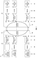
- the electrical system 10 comprises a supply side 20 where, generally, multiple electrical energy generators 22 are connected via connection ports 24, involving conditioning circuits 26 and possibly additional conditioning circuitry 28, into a single DC electrical energy source.
- This energy source is supplied to a common inverter system 30 to convert it to AC for transmission on over a power grid.
- a rectifier 32 takes the AC power from the grid and delivers it to AC and DC loads.
- energy is delivered to multiple loads 42 via connections ports 44 involving conditioning circuits 46 and other conditioning circuitry 48.
- the electrical energy generators 22 include, but are not limited to being: wind turbines; photovoltaic solar cells; storage batteries; ignition engine generator sets; diesel power generator; gas turbines; steam turbines; an asynchronous induction type generator and, a reticulated supply.
- these energy source may generate powers of up to 100 kWs or MWs and this is understood to be medium scale.
- a typical conditioning circuit 26 will now be described with reference to Fig. 2 .
- the conditioning circuit 26 includes an over voltage or "surge suppression" device, being a metal oxide varistor 102.
- Surge suppression devices are intended to protect the port connection circuits 20 from damage caused by excess voltage. Voltage surges may be caused by lightning strikes or switching high currents.
- over voltage protection devices include high power thryristor "diverter” switches, semiconductor avalanche devices and gas discharge devices.
- An alternative conditioning circuit 26 is shown in Fig. 3 .
- an AC electrical generator 22 is connected via rectifier 28 and a conditioning circuit 26 to connection port 24.
- the conditioning circuit 26 includes a DC power filter 104.
- DC power filters are comprised of capacitors, inductors or combinations of both, and are applied to limit the rate of change of voltage (dv/dt) across the connection port 24 or rate of change of current (di/dt) in the DC loop 50.
- Fig. 4 shows exemplary circuitry of the supply side 20 (except for the conditioning circuit).
- a three-phase AC source 220, a single-phase AC source 222 and two DC energy sources 224 and 226 are connected in series to form part of DC loop 50.
- a DC energy generator may be a solar power panel.
- Each AC energy source is first converted to DC using a rectifier bridge 230.
- the flow of power from the rectifier bridge 230 is controlled using a switching regulator to vary the source output voltage and power.
- the switching regulator may be either a voltage step up (up converter) or step down (down converter) device.
- AC source 220 is connected, via a rectifier bridge 230, to a switching regulator 232 configured in voltage boost mode that takes DC input voltage from the rectifier bridge 230 and produces a higher DC output voltage.
- the switching regulator shown 232 is a DC switching device where energy is stored in the inductor duty part of the conversion cycle. Alternately the energy is delivered to the filter capacitor C.
- Some applications may require galvanic (electrical isolation) of the energy source for safety or electrical equipment isolation purposes.
- high speed switching regulators may be used in conjunction with a high frequency isolation transformer.
- DC source 226 is connected to a "flyback" switching regulator 234 with a galvanic isolation transformer 238.
- switching regulators such as buck, buck-boost, push-pull and bridge-type regulators may be used.
- the rectifier bridge 230 that is used in conjunction with an AC energy generating source also enables dynamic connection and disconnection of the source without disturbing the continuity of the series loop circuit. When the generator is disconnected or no power is being generated, the current simply commutates through the DC rectifier diodes via the rectifier DC connections.
- an anti-parallel bypass diode or reverse connected diode 226 provides a path for the loop current when the generated DC generating source is removed or is not generating. Both switching regulators 232, 234 are also shown connected to an anti-parallel bypass diode 236 to provide continuous DC connection.
- bypass diode When a generator is reconnected, the bypass diode is reverse biased by the generated voltage.
- the structure of the series connected energy sources provides for the inclusion of electrical energy storage batteries. These batteries may deliver energy to any or all devices in the loop 50.
- the distribution side 40 On the distribution side 40, various AC and DC loads may be connected into the series DC loop 50.
- the distribution side 40 comprises two DC loads 420 and 422 and a three-phase AC load 424, all connected in series.
- An inverter 426 is required to convert DC to three phase AC to drive the AC load 424.
- Input DC voltage delivered to a DC load is regulated using switching regulator 428, which may be configured to boost up or buck down.
- switching regulator 428 may be configured to boost up or buck down.
- a "flyback" switching regulator with a galvanic isolation transformer may also be used to isolate a load.
- a bypass device or circuit 430 provides for continuous connection of the DC series loop 50 when loads 420, 422 and 424 are connected and disconnected from the loop.
- Examples of a bypass device include a transistor, a thyristor or a mechanical switch.
- Batteries may be selectively incorporated into the electrical energy delivery side 40.
- the battery comprises a series connection of individual cells.
- the total battery voltage is slightly less than the nominal DC link voltage to ensure that the diode 504 is reverse biased under normal conditions.
- the structure of the series connected inverters 426 enables commonly available storage batteries to be selectively incorporated throughout the energy delivery system, as shown in Fig. 6 .
- a nominal DC link voltage V n is provided at the output of the conditioning circuit 46.
- the battery 500 is connected to the DC link 502 of the inverter 426 through a diode 504 that is arranged to be reverse biased, under normal operating conditions, so that no current flows from the battery.
- the battery 500 has charging controls 506 that provide a measured and controlled charging current to maintain the charge in the battery or to recharge the battery after a discharge cycle.
- V n falls below the battery voltage diode 504 will become forward biased, and the battery 500 will deliver energy to maintain the normal operation of inverter 426. This provides "ride through” voltage support under fault conditions in the order of seconds or minutes.
- New batteries are being developed and these are becoming available. These new types offer advantages with increased storage capacity, higher charging and discharging rates, and increased operating life or charge/discharge cycles. Examples include Lithium Polymer and the Altair Nano Lithium cell.
- Super capacitors are high capacitance devices with a low voltage rating.
- the capacitors are arranged in bank, with series and parallel connections, to provide a suitable voltage rating and aggregate energy storage capacity.
- individual capacitors are available as 3,000 Farad 2.8 volt units.
- Capacitor banks comprising 300 capacitors series connected (10 Farad) 750 volt with a discharge cycle between 5 and 30 seconds are suitable for "ride through" support.
- boost switching regulator is used to increases the voltage at diode to maintain the reverse biased condition under normal operations, and to maintain the DC link voltage as the capacitor charge reduces.
- the total DC voltage may be supplied directly as DC power to loads without the intervention of a three-phase AC electrical power grid.
- inverters 426 on the energy delivery side 40 may be arranged and connected to deliver aggregated energy to a load such as AC power distribution grid.
- the aggregation or summation of plural parallel inverter outputs may be achieved by connecting plural individual inverters to individual primary windings 600 on a multi-primary winding transformer 602.
- the individual inverters 426 may be synchronised to develop a sinusoidal voltage on transformer secondary or load side winding.
- the inverter controls modulate the DC link voltage with techniques including pulse width modulation, edge modulation, square wave or multilevel modulation.
- the inverters may either single phase ("H" bridge), three phase systems or a combination of single and multi-phase inverters.
- the inverters may be coordinated to operate in voltage summation mode with a common transformer secondary winding 604.
- the inverters may be coordinated to operate in a "parallel" or current summation mode by applying multiple transformers with the secondary windings connected in parallel.
- the multiple inverter connection enables the inverter outputs to be phase shifted to accommodate various transformer winding connections and vector groups on the primary or secondary side of the transformer.
- the multiple inverter connection also enables the inverter outputs to be slightly phase shifted to cancel specific harmonic voltages.
- the individual inverters conditioning circuit may include a voltage regulator to maintain a constant DC link voltage at the inverter.
- the voltage regulator may be a boost or buck switching regulator.
Claims (10)
- Système de fourniture et de distribution d'énergie électrique (10) approprié pour une fourniture à échelle moyenne, comprenant un côté fourniture (20) pour fournir de l'énergie électrique et un côté distribution (40) pour distribuer de l'énergie électrique,(i) le côté fourniture comprenant :des générateurs d'énergie CA électrique (22) pour générer de la puissance CA etune première pluralité de ports de connexion (24) pour une connexion sélective aux générateurs d'énergie CA électrique, chaque port de connexion de la première pluralité de ports de connexion incluantune entrée CA pour recevoir de l'énergie électrique CA provenant d'un générateur de CA électrique des générateurs de CA électrique,une sortie CC bipolaire pour apporter de la puissance de sortie CC à une tension CC,une dérivation permettant au courant continu de s'écouler à travers le port de connexion lorsqu'aucun générateur n'est connecté au niveau de l'entrée CA du port,un pont redresseur (230) pour convertir la puissance CA provenant du générateur connecté à l'entrée CA du port en puissance CC, etun régulateur de commutation (232) connecté au pont redresseur et à la sortie CC pour commander l'écoulement de puissance depuis le générateur d'énergie électrique et pour faire varier la tension de sortie CC et la puissance de sortie CC ;(ii) le côté distribution comprenant :des charges d'énergie CA électrique (42) etune seconde pluralité de ports de connexion (44) pour une connexion sélective aux charges d'énergie CA électrique, chaque port de connexion de la seconde pluralité de ports de connexion incluant :une entrée CC bipolaire pour recevoir de la puissance d'entrée CC à une tension d'entrée CC,une sortie CA pour apporter de la puissance de sortie CA aux charges d'énergie CA électrique,une dérivation (430) permettant au courant continu de s'écouler à travers l'entrée CC du port lorsqu'aucune charge n'est connectée au niveau de la sortie CA du port,un régulateur de tension pour maintenir la tension d'entrée CC constante,une batterie (500) ou un super-condensateur connecté à une sortie du régulateur de tension, etun onduleur (30) connecté à la sortie du régulateur de tension et à la sortie CA du port pour générer et faire varier la puissance de sortie CA et distribuer la puissance de sortie CA à la charge d'énergie CA électrique connectée au port,
système caractérisé en ce que
les sorties CC du côté fourniture et les entrées CC du côté distribution sont connectées en série pour former une boucle à courant continu (50). - Système de fourniture et de distribution d'énergie électrique selon la revendication 1, dans lequel les générateurs d'énergie CA électrique (22) sont un ou plusieurs parmi :un générateur de puissance diesel,un générateur moteur, une turbine à gaz,un générateur à turbine marémotrice,une turbine à vapeur, ouune fourniture réticulée.
- Système de fourniture et de distribution d'énergie électrique selon l'une quelconque des revendications précédentes, dans lequel le pont redresseur (230) sert également de dérivation supplémentaire pour permettre au courant continu de s'écouler à travers la sortie CC du port de connexion lorsque le générateur est retiré de la boucle.
- Système de fourniture et de distribution d'énergie électrique selon l'une quelconque des revendications précédentes, comprenant en outre un transformateur connecté entre le générateur CA et le pont redresseur (230).
- Système de fourniture et de distribution d'énergie électrique selon l'une quelconque des revendications précédentes, dans lequel le générateur électrique est un générateur de type à induction asynchrone connecté à un générateur de puissance de magnétisation réactive (VAR).
- Système de fourniture et de distribution d'énergie électrique selon l'une quelconque des revendications précédentes, dans lequel la dérivation pour le générateur électrique est une diode (226).
- Système de fourniture et de distribution d'énergie électrique selon l'une quelconque des revendications précédentes, dans lequel le régulateur de tension de commutation est un régulateur de commutation « indirect » (234).
- Système de fourniture et de distribution d'énergie électrique selon l'une quelconque des revendications précédentes, comprenant en outre un transformateur d'isolation galvanique pour isoler une charge.
- Système de fourniture et de distribution d'énergie électrique selon l'une quelconque des revendications précédentes, dans lequel la dérivation (430) sur le côté distribution est un transistor, un thyristor ou un commutateur mécanique.
- Système de fourniture et de distribution d'énergie électrique selon l'une quelconque des revendications précédentes dans lequel les onduleurs (426) du côté distribution comprennent plusieurs sorties d'onduleur parallèles connectées à des enroulements primaires individuels (600) d'un circuit de synchronisation de transformateur à multiples enroulements primaires (602) pour développer une tension sinusoïdale sur un enroulement secondaire (604) du transformateur, et l'enroulement secondaire du transformateur à multiples enroulements primaires connecté à la charge d'énergie CA.
Applications Claiming Priority (2)
| Application Number | Priority Date | Filing Date | Title |
|---|---|---|---|
| AU2007906247A AU2007906247A0 (en) | 2007-11-14 | Electrical Energy and Distribution System | |
| PCT/AU2008/001542 WO2009062227A1 (fr) | 2007-11-14 | 2008-10-17 | Système de fourniture et de distribution d'énergie électrique |
Publications (3)
| Publication Number | Publication Date |
|---|---|
| EP2220734A1 EP2220734A1 (fr) | 2010-08-25 |
| EP2220734A4 EP2220734A4 (fr) | 2017-02-08 |
| EP2220734B1 true EP2220734B1 (fr) | 2020-01-22 |
Family
ID=40638226
Family Applications (1)
| Application Number | Title | Priority Date | Filing Date |
|---|---|---|---|
| EP08850295.0A Active EP2220734B1 (fr) | 2007-11-14 | 2008-10-17 | Système de fourniture et de distribution d'énergie électrique |
Country Status (5)
| Country | Link |
|---|---|
| US (1) | US9142964B2 (fr) |
| EP (1) | EP2220734B1 (fr) |
| AU (1) | AU2008323597B2 (fr) |
| NZ (1) | NZ585511A (fr) |
| WO (1) | WO2009062227A1 (fr) |
Families Citing this family (18)
| Publication number | Priority date | Publication date | Assignee | Title |
|---|---|---|---|---|
| US8097967B2 (en) | 2008-06-30 | 2012-01-17 | Demand Energy Networks, Inc. | Energy systems, energy devices, energy utilization methods, and energy transfer methods |
| AU2010283965B2 (en) * | 2009-08-21 | 2015-01-29 | Renergyx Pty Limited | Electrical energy distribution system with ride-through capability |
| FR2958814B1 (fr) * | 2010-04-07 | 2012-08-03 | Italo Bregoli | Elevateur rapide de tension electrique generateur de courant optimisable, a haut rendement, par complementation asservie d'une source existante a tension fixe ou fluctuante, du watt au megawatt |
| US9324116B2 (en) | 2011-02-21 | 2016-04-26 | Spirae, Inc. | Energy services interface |
| ES2820542T3 (es) * | 2011-03-16 | 2021-04-21 | Sma Solar Technology Ag | Ondulador acoplado a una red, disposición de onduladores y procedimiento para hacer funcionar una disposición de onduladores |
| US9525285B2 (en) | 2011-06-13 | 2016-12-20 | Demand Energy Networks, Inc. | Energy systems and energy supply methods |
| US9602025B2 (en) * | 2013-07-12 | 2017-03-21 | Infineon Technologies Austria Ag | Multiphase power converter circuit and method |
| NL2013296B1 (nl) * | 2014-08-01 | 2016-09-21 | Citytec B V | Systeem voor het distribueren van elektrische energie. |
| US9438101B1 (en) | 2015-05-07 | 2016-09-06 | Qm Power, Inc. | High speed switching solid state relay circuit |
| US9800051B2 (en) * | 2015-09-03 | 2017-10-24 | Ensync, Inc. | Method and apparatus for controlling energy flow between dissimilar energy storage devices |
| CN108369921B (zh) * | 2015-12-07 | 2023-12-12 | 应用材料公司 | 使用静电夹盘夹持及解夹持基板的方法及装置 |
| US10034067B1 (en) * | 2017-02-27 | 2018-07-24 | Summit Esp, Llc | System, method and apparatus for autonomous data collection from variable frequency drives |
| US10461542B2 (en) | 2017-07-10 | 2019-10-29 | Ge Aviation Systems Llc | Power distribution network |
| AU2019227093A1 (en) * | 2018-03-01 | 2020-09-03 | Crone Geophysics & Exploration Ltd. | Method for securing power in remote locations and apparatus therefor |
| CN109066802A (zh) * | 2018-10-19 | 2018-12-21 | 国家电网有限公司 | 一种微电网能量管理系统及方法 |
| CN110994566B (zh) * | 2019-12-04 | 2022-03-29 | 南京南瑞继保工程技术有限公司 | 一种机械开关触发回路及控制方法 |
| WO2021133718A1 (fr) * | 2019-12-23 | 2021-07-01 | Marquette University | Convertisseur de puissance multiport |
| US11762447B2 (en) * | 2021-12-22 | 2023-09-19 | Schweitzer Engineering Laboratories, Inc. | Power supply with boost stage to improve ride through performance |
Family Cites Families (38)
| Publication number | Priority date | Publication date | Assignee | Title |
|---|---|---|---|---|
| JPS4521047B1 (fr) * | 1967-09-26 | 1970-07-17 | ||
| SE380687B (sv) * | 1974-03-15 | 1975-11-10 | Asea Ab | Forfarande vid drift av en tvapolig likstromsoverforing jemte likstromsoverforing avsedd att drivas enligt forfarandet. |
| DE2435755A1 (de) * | 1974-07-25 | 1976-02-05 | Bbc Brown Boveri & Cie | Energieuebertragungssystem mit sammelleitung fuer gleichstrom |
| US4057736A (en) * | 1974-09-13 | 1977-11-08 | Jeppson Morris R | Electrical power generation and distribution system |
| US4035659A (en) * | 1975-10-20 | 1977-07-12 | Jeppson Morris R | Electrical power-generation apparatus with rotary voltage transformer and integrated inertial energy storage |
| US4791349A (en) * | 1982-03-15 | 1988-12-13 | Minks Floyd D | Electric power system |
| US4780659A (en) * | 1987-04-01 | 1988-10-25 | Sundstrand Corporation | High-power, high-voltage direct current power source |
| JPH01311820A (ja) * | 1988-02-09 | 1989-12-15 | Fuji Electric Co Ltd | 閉ループ配電系統における事故点検出方法 |
| US5355296A (en) * | 1992-12-10 | 1994-10-11 | Sundstrand Corporation | Switching converter and summing transformer for use therein |
| JP2833460B2 (ja) * | 1993-12-27 | 1998-12-09 | 株式会社日立製作所 | 電源システム |
| US5745670A (en) * | 1996-06-11 | 1998-04-28 | Lanart Corporation | Fault tolerant power supply system |
| WO1998028832A1 (fr) * | 1996-12-20 | 1998-07-02 | Manuel Dos Santos Da Ponte | Dispositif generateur hybride |
| DE19752661C2 (de) * | 1997-11-27 | 2001-09-13 | Siemens Ag | Bordnetz für ein Kraftfahrzeug |
| JPH11330521A (ja) * | 1998-03-13 | 1999-11-30 | Canon Inc | 太陽電池モジュ―ル、太陽電池アレイ、太陽光発電装置、太陽電池モジュ―ルの故障特定方法 |
| US5962929A (en) * | 1998-04-22 | 1999-10-05 | Lockheed Martin Corporation | Fault tolerant power distribution |
| JP2001028848A (ja) * | 1999-07-12 | 2001-01-30 | Japan Nuclear Cycle Development Inst States Of Projects | 非常用発電機によるバックアップシステム |
| US6184593B1 (en) * | 1999-07-29 | 2001-02-06 | Abb Power T&D Company Inc. | Uninterruptible power supply |
| KR20010011621A (ko) | 1999-07-29 | 2001-02-15 | 윤종용 | 소규모 분산 계통연계형의 태양광 및 디젤 복합 발전시스템 |
| US6624533B1 (en) * | 1999-08-04 | 2003-09-23 | Westerbeke Corporation | Controlling generator power |
| US6975098B2 (en) * | 2002-01-31 | 2005-12-13 | Vlt, Inc. | Factorized power architecture with point of load sine amplitude converters |
| JP2005526363A (ja) * | 2002-05-16 | 2005-09-02 | バラード パワー システムズ インコーポレイティド | 調節可能な燃料電池システムのアレイを備える電源設備 |
| JP3825020B2 (ja) * | 2002-08-01 | 2006-09-20 | 株式会社アイ・ヒッツ研究所 | 分散給電システム |
| CA2494285A1 (fr) * | 2002-09-13 | 2004-03-25 | Proton Energy Systems, Inc. | Procede et systeme pour le controle equilibre de puissance electrique desecours |
| US20040155603A1 (en) * | 2002-10-23 | 2004-08-12 | Clegg John C. | Direct current gas discharge lighting systems with arc suppression |
| US6960838B2 (en) * | 2002-11-15 | 2005-11-01 | Sprint Communications Company L.P. | Power system for a telecommunication facility |
| US7548441B2 (en) * | 2004-02-24 | 2009-06-16 | Vlt, Inc. | Universal AC adapter |
| US7000395B2 (en) * | 2004-03-11 | 2006-02-21 | Yuan Ze University | Hybrid clean-energy power-supply framework |
| US7400065B2 (en) * | 2004-08-24 | 2008-07-15 | Honeywell International Inc. | Electrical power distribution system and method with active load control |
| US20060055175A1 (en) * | 2004-09-14 | 2006-03-16 | Grinblat Zinovy D | Hybrid thermodynamic cycle and hybrid energy system |
| US7864497B2 (en) * | 2005-01-26 | 2011-01-04 | Guenther Spelsberg Gmbh & Co. Kg | Protective circuit |
| US20060237058A1 (en) * | 2005-04-25 | 2006-10-26 | Mcclintock Ronald B | Direct current combiner box with power monitoring, ground fault detection and communications interface |
| FR2900636B1 (fr) * | 2006-05-05 | 2009-03-06 | Hispano Suiza Sa | Circuit d'alimentation en energie electrique pour des equipements electriques d'un moteur d'aeronef ou de son environnement |
| US7474016B2 (en) * | 2006-05-23 | 2009-01-06 | Continental Automotive Systems Us, Inc. | System and method for responding to abrupt load changes on a power system |
| US7518266B2 (en) * | 2006-11-01 | 2009-04-14 | Electric Power Research Institute, Inc. | Method and apparatus for improving AC transmission system dispatchability, system stability, and power flow controllability using DC transmission systems |
| US7900361B2 (en) * | 2006-12-06 | 2011-03-08 | Solaredge, Ltd. | Current bypass for distributed power harvesting systems using DC power sources |
| US7851943B2 (en) * | 2006-12-08 | 2010-12-14 | General Electric Company | Direct current power transmission and distribution system |
| US7525211B2 (en) * | 2007-06-19 | 2009-04-28 | Marvin Russell H | Control system for twin turbine wind power generating system |
| US8138624B2 (en) * | 2008-06-23 | 2012-03-20 | Ming-Hsiang Yeh | Conversion device for automobile |
-
2008
- 2008-10-17 WO PCT/AU2008/001542 patent/WO2009062227A1/fr active Application Filing
- 2008-10-17 NZ NZ58551108A patent/NZ585511A/xx unknown
- 2008-10-17 US US12/742,421 patent/US9142964B2/en active Active
- 2008-10-17 EP EP08850295.0A patent/EP2220734B1/fr active Active
- 2008-10-17 AU AU2008323597A patent/AU2008323597B2/en active Active
Non-Patent Citations (1)
| Title |
|---|
| None * |
Also Published As
| Publication number | Publication date |
|---|---|
| AU2008323597B2 (en) | 2012-04-19 |
| EP2220734A4 (fr) | 2017-02-08 |
| WO2009062227A1 (fr) | 2009-05-22 |
| NZ585511A (en) | 2013-02-22 |
| AU2008323597A1 (en) | 2009-05-22 |
| EP2220734A1 (fr) | 2010-08-25 |
| US20100320837A1 (en) | 2010-12-23 |
| US9142964B2 (en) | 2015-09-22 |
Similar Documents
| Publication | Publication Date | Title |
|---|---|---|
| EP2220734B1 (fr) | Système de fourniture et de distribution d'énergie électrique | |
| Saeedifard et al. | DC power systems: Challenges and opportunities | |
| EP2477299B1 (fr) | Contrôle de conversion de puissance avec stockage d'énergie | |
| US9293917B2 (en) | Energy storage system | |
| Khadem et al. | UPQC for power quality improvement in dg integrated smart grid network-a review | |
| Krishnamoorthy et al. | Wind turbine generator–battery energy storage utility interface converter topology with medium-frequency transformer link | |
| EP2671310B1 (fr) | Convertisseur électronique de puissance | |
| WO2002027892A1 (fr) | Reseau local de distribution d'electricite | |
| An et al. | Multi-functional DC collector for future ALL-DC offshore wind power system: Concept, scheme, and implement | |
| Khadem et al. | Integration of UPQC for Power Quality improvement in distributed generation network-a review | |
| Li et al. | Analysis of bidirectional 15 MW current source DC/DC converter for series-connected superconducting-based 1 GW/100 kV offshore wind farm | |
| Vijayakumar et al. | Compensation of voltage variations in distribution system by using DVR based separate energy storage devices | |
| WO2018060129A1 (fr) | Système de convertisseur de puissance pour compenser la qualité de puissance et équilibrer la charge, connecté à un réseau de distribution d'énergie électrique | |
| Zhou et al. | The study of power electronic transformer on power flow control and voltage regulation in DC micro-grid | |
| EP2467917B1 (fr) | Système de délivrance d'énergie électrique à capacité de maintien d'alimentation en cas de chute de tension | |
| Meegahapola et al. | Investigation of fault ride-through capability of AC/DC hybrid microgrids during AC network faults | |
| Sarrias-Mena et al. | Modelling and control of a medium-voltage DC distribution system with energy storage | |
| Li et al. | A hybrid energy system using cascaded H-bridge converter | |
| Shrivastava et al. | Overview strategy of wind farm in VSC-HVDC power transmission | |
| Photovoltaic | Grid voltage stability enhancement using photovoltaic based static synchronous compensator | |
| Feng et al. | Recovery control for hybrid MTDC systems with offshore wind farms supplying weak grids | |
| Daud et al. | A novel coordinated control strategy of PV/BES system considering power smoothing | |
| Carmeli et al. | Universal digital controller for power quality and distributed generation systems | |
| Kadandani et al. | On Exploring the Power Quality Enhancement Capability and Other Ancillary Functionalities of Solid State Transformer Application in the Distribution System | |
| Yu et al. | Startup Strategy of the HVDC System Based on Flexible Diode Rectifier for Offshore Wind Farms |
Legal Events
| Date | Code | Title | Description |
|---|---|---|---|
| PUAI | Public reference made under article 153(3) epc to a published international application that has entered the european phase |
Free format text: ORIGINAL CODE: 0009012 |
|
| 17P | Request for examination filed |
Effective date: 20100610 |
|
| AK | Designated contracting states |
Kind code of ref document: A1 Designated state(s): AT BE BG CH CY CZ DE DK EE ES FI FR GB GR HR HU IE IS IT LI LT LU LV MC MT NL NO PL PT RO SE SI SK TR |
|
| AX | Request for extension of the european patent |
Extension state: AL BA MK RS |
|
| DAX | Request for extension of the european patent (deleted) | ||
| RA4 | Supplementary search report drawn up and despatched (corrected) |
Effective date: 20170110 |
|
| RIC1 | Information provided on ipc code assigned before grant |
Ipc: H02J 3/38 20060101ALI20170103BHEP Ipc: H02M 7/00 20060101ALI20170103BHEP Ipc: H02J 1/00 20060101ALI20170103BHEP Ipc: H02J 3/36 20060101AFI20170103BHEP Ipc: H02M 1/00 20070101ALN20170103BHEP Ipc: H02B 1/00 20060101ALI20170103BHEP |
|
| STAA | Information on the status of an ep patent application or granted ep patent |
Free format text: STATUS: EXAMINATION IS IN PROGRESS |
|
| 17Q | First examination report despatched |
Effective date: 20180724 |
|
| REG | Reference to a national code |
Ref country code: DE Ref legal event code: R079 Ref document number: 602008062052 Country of ref document: DE Free format text: PREVIOUS MAIN CLASS: H02B0001000000 Ipc: H02J0001040000 |
|
| GRAP | Despatch of communication of intention to grant a patent |
Free format text: ORIGINAL CODE: EPIDOSNIGR1 |
|
| STAA | Information on the status of an ep patent application or granted ep patent |
Free format text: STATUS: GRANT OF PATENT IS INTENDED |
|
| RIC1 | Information provided on ipc code assigned before grant |
Ipc: H02M 1/00 20060101ALN20190718BHEP Ipc: H02J 1/00 20060101ALI20190718BHEP Ipc: H02J 1/04 20060101AFI20190718BHEP Ipc: H02J 3/38 20060101ALI20190718BHEP Ipc: H02B 1/00 20060101ALI20190718BHEP Ipc: H02J 3/36 20060101ALI20190718BHEP Ipc: H02M 7/00 20060101ALI20190718BHEP |
|
| INTG | Intention to grant announced |
Effective date: 20190806 |
|
| GRAS | Grant fee paid |
Free format text: ORIGINAL CODE: EPIDOSNIGR3 |
|
| GRAA | (expected) grant |
Free format text: ORIGINAL CODE: 0009210 |
|
| STAA | Information on the status of an ep patent application or granted ep patent |
Free format text: STATUS: THE PATENT HAS BEEN GRANTED |
|
| AK | Designated contracting states |
Kind code of ref document: B1 Designated state(s): AT BE BG CH CY CZ DE DK EE ES FI FR GB GR HR HU IE IS IT LI LT LU LV MC MT NL NO PL PT RO SE SI SK TR |
|
| REG | Reference to a national code |
Ref country code: GB Ref legal event code: FG4D |
|
| REG | Reference to a national code |
Ref country code: CH Ref legal event code: EP |
|
| REG | Reference to a national code |
Ref country code: DE Ref legal event code: R096 Ref document number: 602008062052 Country of ref document: DE |
|
| REG | Reference to a national code |
Ref country code: AT Ref legal event code: REF Ref document number: 1227557 Country of ref document: AT Kind code of ref document: T Effective date: 20200215 |
|
| REG | Reference to a national code |
Ref country code: IE Ref legal event code: FG4D |
|
| REG | Reference to a national code |
Ref country code: NL Ref legal event code: MP Effective date: 20200122 |
|
| REG | Reference to a national code |
Ref country code: LT Ref legal event code: MG4D |
|
| PG25 | Lapsed in a contracting state [announced via postgrant information from national office to epo] |
Ref country code: NL Free format text: LAPSE BECAUSE OF FAILURE TO SUBMIT A TRANSLATION OF THE DESCRIPTION OR TO PAY THE FEE WITHIN THE PRESCRIBED TIME-LIMIT Effective date: 20200122 Ref country code: PT Free format text: LAPSE BECAUSE OF FAILURE TO SUBMIT A TRANSLATION OF THE DESCRIPTION OR TO PAY THE FEE WITHIN THE PRESCRIBED TIME-LIMIT Effective date: 20200614 Ref country code: NO Free format text: LAPSE BECAUSE OF FAILURE TO SUBMIT A TRANSLATION OF THE DESCRIPTION OR TO PAY THE FEE WITHIN THE PRESCRIBED TIME-LIMIT Effective date: 20200422 Ref country code: FI Free format text: LAPSE BECAUSE OF FAILURE TO SUBMIT A TRANSLATION OF THE DESCRIPTION OR TO PAY THE FEE WITHIN THE PRESCRIBED TIME-LIMIT Effective date: 20200122 |
|
| PG25 | Lapsed in a contracting state [announced via postgrant information from national office to epo] |
Ref country code: GR Free format text: LAPSE BECAUSE OF FAILURE TO SUBMIT A TRANSLATION OF THE DESCRIPTION OR TO PAY THE FEE WITHIN THE PRESCRIBED TIME-LIMIT Effective date: 20200423 Ref country code: HR Free format text: LAPSE BECAUSE OF FAILURE TO SUBMIT A TRANSLATION OF THE DESCRIPTION OR TO PAY THE FEE WITHIN THE PRESCRIBED TIME-LIMIT Effective date: 20200122 Ref country code: SE Free format text: LAPSE BECAUSE OF FAILURE TO SUBMIT A TRANSLATION OF THE DESCRIPTION OR TO PAY THE FEE WITHIN THE PRESCRIBED TIME-LIMIT Effective date: 20200122 Ref country code: IS Free format text: LAPSE BECAUSE OF FAILURE TO SUBMIT A TRANSLATION OF THE DESCRIPTION OR TO PAY THE FEE WITHIN THE PRESCRIBED TIME-LIMIT Effective date: 20200522 Ref country code: BG Free format text: LAPSE BECAUSE OF FAILURE TO SUBMIT A TRANSLATION OF THE DESCRIPTION OR TO PAY THE FEE WITHIN THE PRESCRIBED TIME-LIMIT Effective date: 20200422 Ref country code: LV Free format text: LAPSE BECAUSE OF FAILURE TO SUBMIT A TRANSLATION OF THE DESCRIPTION OR TO PAY THE FEE WITHIN THE PRESCRIBED TIME-LIMIT Effective date: 20200122 |
|
| REG | Reference to a national code |
Ref country code: DE Ref legal event code: R097 Ref document number: 602008062052 Country of ref document: DE |
|
| PG25 | Lapsed in a contracting state [announced via postgrant information from national office to epo] |
Ref country code: DK Free format text: LAPSE BECAUSE OF FAILURE TO SUBMIT A TRANSLATION OF THE DESCRIPTION OR TO PAY THE FEE WITHIN THE PRESCRIBED TIME-LIMIT Effective date: 20200122 Ref country code: LT Free format text: LAPSE BECAUSE OF FAILURE TO SUBMIT A TRANSLATION OF THE DESCRIPTION OR TO PAY THE FEE WITHIN THE PRESCRIBED TIME-LIMIT Effective date: 20200122 Ref country code: RO Free format text: LAPSE BECAUSE OF FAILURE TO SUBMIT A TRANSLATION OF THE DESCRIPTION OR TO PAY THE FEE WITHIN THE PRESCRIBED TIME-LIMIT Effective date: 20200122 Ref country code: EE Free format text: LAPSE BECAUSE OF FAILURE TO SUBMIT A TRANSLATION OF THE DESCRIPTION OR TO PAY THE FEE WITHIN THE PRESCRIBED TIME-LIMIT Effective date: 20200122 Ref country code: CZ Free format text: LAPSE BECAUSE OF FAILURE TO SUBMIT A TRANSLATION OF THE DESCRIPTION OR TO PAY THE FEE WITHIN THE PRESCRIBED TIME-LIMIT Effective date: 20200122 Ref country code: ES Free format text: LAPSE BECAUSE OF FAILURE TO SUBMIT A TRANSLATION OF THE DESCRIPTION OR TO PAY THE FEE WITHIN THE PRESCRIBED TIME-LIMIT Effective date: 20200122 Ref country code: SK Free format text: LAPSE BECAUSE OF FAILURE TO SUBMIT A TRANSLATION OF THE DESCRIPTION OR TO PAY THE FEE WITHIN THE PRESCRIBED TIME-LIMIT Effective date: 20200122 |
|
| REG | Reference to a national code |
Ref country code: AT Ref legal event code: MK05 Ref document number: 1227557 Country of ref document: AT Kind code of ref document: T Effective date: 20200122 |
|
| PLBE | No opposition filed within time limit |
Free format text: ORIGINAL CODE: 0009261 |
|
| STAA | Information on the status of an ep patent application or granted ep patent |
Free format text: STATUS: NO OPPOSITION FILED WITHIN TIME LIMIT |
|
| 26N | No opposition filed |
Effective date: 20201023 |
|
| PG25 | Lapsed in a contracting state [announced via postgrant information from national office to epo] |
Ref country code: IT Free format text: LAPSE BECAUSE OF FAILURE TO SUBMIT A TRANSLATION OF THE DESCRIPTION OR TO PAY THE FEE WITHIN THE PRESCRIBED TIME-LIMIT Effective date: 20200122 Ref country code: AT Free format text: LAPSE BECAUSE OF FAILURE TO SUBMIT A TRANSLATION OF THE DESCRIPTION OR TO PAY THE FEE WITHIN THE PRESCRIBED TIME-LIMIT Effective date: 20200122 |
|
| PG25 | Lapsed in a contracting state [announced via postgrant information from national office to epo] |
Ref country code: SI Free format text: LAPSE BECAUSE OF FAILURE TO SUBMIT A TRANSLATION OF THE DESCRIPTION OR TO PAY THE FEE WITHIN THE PRESCRIBED TIME-LIMIT Effective date: 20200122 Ref country code: PL Free format text: LAPSE BECAUSE OF FAILURE TO SUBMIT A TRANSLATION OF THE DESCRIPTION OR TO PAY THE FEE WITHIN THE PRESCRIBED TIME-LIMIT Effective date: 20200122 |
|
| REG | Reference to a national code |
Ref country code: CH Ref legal event code: PL |
|
| PG25 | Lapsed in a contracting state [announced via postgrant information from national office to epo] |
Ref country code: LU Free format text: LAPSE BECAUSE OF NON-PAYMENT OF DUE FEES Effective date: 20201017 Ref country code: MC Free format text: LAPSE BECAUSE OF FAILURE TO SUBMIT A TRANSLATION OF THE DESCRIPTION OR TO PAY THE FEE WITHIN THE PRESCRIBED TIME-LIMIT Effective date: 20200122 |
|
| REG | Reference to a national code |
Ref country code: BE Ref legal event code: MM Effective date: 20201031 |
|
| PG25 | Lapsed in a contracting state [announced via postgrant information from national office to epo] |
Ref country code: BE Free format text: LAPSE BECAUSE OF NON-PAYMENT OF DUE FEES Effective date: 20201031 Ref country code: CH Free format text: LAPSE BECAUSE OF NON-PAYMENT OF DUE FEES Effective date: 20201031 Ref country code: LI Free format text: LAPSE BECAUSE OF NON-PAYMENT OF DUE FEES Effective date: 20201031 |
|
| PG25 | Lapsed in a contracting state [announced via postgrant information from national office to epo] |
Ref country code: IE Free format text: LAPSE BECAUSE OF NON-PAYMENT OF DUE FEES Effective date: 20201017 |
|
| PG25 | Lapsed in a contracting state [announced via postgrant information from national office to epo] |
Ref country code: TR Free format text: LAPSE BECAUSE OF FAILURE TO SUBMIT A TRANSLATION OF THE DESCRIPTION OR TO PAY THE FEE WITHIN THE PRESCRIBED TIME-LIMIT Effective date: 20200122 Ref country code: MT Free format text: LAPSE BECAUSE OF FAILURE TO SUBMIT A TRANSLATION OF THE DESCRIPTION OR TO PAY THE FEE WITHIN THE PRESCRIBED TIME-LIMIT Effective date: 20200122 Ref country code: CY Free format text: LAPSE BECAUSE OF FAILURE TO SUBMIT A TRANSLATION OF THE DESCRIPTION OR TO PAY THE FEE WITHIN THE PRESCRIBED TIME-LIMIT Effective date: 20200122 |
|
| PGFP | Annual fee paid to national office [announced via postgrant information from national office to epo] |
Ref country code: FR Payment date: 20221021 Year of fee payment: 15 |
|
| PGFP | Annual fee paid to national office [announced via postgrant information from national office to epo] |
Ref country code: GB Payment date: 20221013 Year of fee payment: 15 Ref country code: DE Payment date: 20221018 Year of fee payment: 15 |