EP2220412B1 - Gate valve for a vacuum chamber and vacuum chamber - Google Patents
Gate valve for a vacuum chamber and vacuum chamber Download PDFInfo
- Publication number
- EP2220412B1 EP2220412B1 EP08864682.3A EP08864682A EP2220412B1 EP 2220412 B1 EP2220412 B1 EP 2220412B1 EP 08864682 A EP08864682 A EP 08864682A EP 2220412 B1 EP2220412 B1 EP 2220412B1
- Authority
- EP
- European Patent Office
- Prior art keywords
- gate valve
- longitudinal direction
- carrier
- sealing plate
- parallel
- Prior art date
- Legal status (The legal status is an assumption and is not a legal conclusion. Google has not performed a legal analysis and makes no representation as to the accuracy of the status listed.)
- Not-in-force
Links
Images

Classifications
-
- F—MECHANICAL ENGINEERING; LIGHTING; HEATING; WEAPONS; BLASTING
- F16—ENGINEERING ELEMENTS AND UNITS; GENERAL MEASURES FOR PRODUCING AND MAINTAINING EFFECTIVE FUNCTIONING OF MACHINES OR INSTALLATIONS; THERMAL INSULATION IN GENERAL
- F16K—VALVES; TAPS; COCKS; ACTUATING-FLOATS; DEVICES FOR VENTING OR AERATING
- F16K51/00—Other details not peculiar to particular types of valves or cut-off apparatus
- F16K51/02—Other details not peculiar to particular types of valves or cut-off apparatus specially adapted for high-vacuum installations
-
- F—MECHANICAL ENGINEERING; LIGHTING; HEATING; WEAPONS; BLASTING
- F16—ENGINEERING ELEMENTS AND UNITS; GENERAL MEASURES FOR PRODUCING AND MAINTAINING EFFECTIVE FUNCTIONING OF MACHINES OR INSTALLATIONS; THERMAL INSULATION IN GENERAL
- F16K—VALVES; TAPS; COCKS; ACTUATING-FLOATS; DEVICES FOR VENTING OR AERATING
- F16K3/00—Gate valves or sliding valves, i.e. cut-off apparatus with closing members having a sliding movement along the seat for opening and closing
- F16K3/02—Gate valves or sliding valves, i.e. cut-off apparatus with closing members having a sliding movement along the seat for opening and closing with flat sealing faces; Packings therefor
- F16K3/16—Gate valves or sliding valves, i.e. cut-off apparatus with closing members having a sliding movement along the seat for opening and closing with flat sealing faces; Packings therefor with special arrangements for separating the sealing faces or for pressing them together
- F16K3/18—Gate valves or sliding valves, i.e. cut-off apparatus with closing members having a sliding movement along the seat for opening and closing with flat sealing faces; Packings therefor with special arrangements for separating the sealing faces or for pressing them together by movement of the closure members
- F16K3/182—Gate valves or sliding valves, i.e. cut-off apparatus with closing members having a sliding movement along the seat for opening and closing with flat sealing faces; Packings therefor with special arrangements for separating the sealing faces or for pressing them together by movement of the closure members by means of toggle links
Definitions
- the invention concerns a gate valve for closing openings in a wall of a vacuum chamber where diverse processing steps like physical vapour deposition, plasma etching etc. can be carried out as well as a vacuum chamber comprising at least one such gate valve.
- JP 60 222 670 A shows a gate valve of the generic type where a carrier with a sealing plate fixed to it is connected by two parallel links to an actuating rod reciprocatable in a vertical direction parallel to a vertical front of a frame structure which is interrupted by an opening.
- an inactive position of the sealing plate the latter is kept at a distance from the front by the action of a spring.
- Upward motion of the actuating rod causes the sealing plate to reach a stop extending from the front which, upon further upward movement of the actuating rod, deflects the motion of carrier horizontally towards the front whereby the sealing plate eventually reaches an active position where it seals the opening.
- sealing member is not linked to the frame structure but merely to the actuating rod its position relative to the front cannot be controlled with great precision. This may be disadvantageous, in particular, when the sealing plate is in its active position where it must reliably seal the opening even under severe mechanical stresses caused by substantial pressure differences. The fact that the sealing member slides along the stop may lead to the formation of nanoparticles which may in turn result in damage to the articles processed in the vacuum chamber.
- FR 1 493 479 A shows a stop valve of similar structure.
- a round sealing member is mounted on a carrier plate which is connected to an actuating rod by two pairs of parallel links.
- two rollers mounted on the carrier reach horizontal strips which act as a stop for the carrier the latter is forced to move horizontally into a position where the sealing member abuts against an end of a tube, sealing the circular opening of the latter.
- a stop valve of virtually identical structure is described in GB 257 254 A .
- the invention provides a gate valve which is simple, space-saving and reliable and can be actuated by a simple linear drive, e.g., a piston. It also offers facile maintenance, being easy to assemble and disassemble.
- the invention also provides a vacuum chamber which is easy to use and reliable and has a relatively small footprint.
- the vacuum chamber which may be part of an assembly of vacuum chambers with a transport unit as shown in US 5 693 238 A comprises ( Fig. 1 ) a frame structure consisting of an outer frame 1 which surrounds a relatively large essentially oblong frame opening. The latter is filled by several also essentially oblong wall plates 2 which follow upon each other in a longitudinal direction which coincides with the vertical. Each of the wall plates 2 is provided with two slot-like openings 3 which are arranged one above the other and extend essentially over the wall plate 2 in a lateral direction which is perpendicular to the longitudinal direction and consequently horizontal. Through each of the openings 3 a compartment of the vacuum chamber is accessible. Each opening 3 is surrounded by an O-ring 4 as an elastic sealing means.
- the frame structure i.e., the outer frame 1 and the wall plates 2, define a substantially plane front facing away from the compartments which contains the openings 3.
- a gate valve for sealing the openings 3 is arranged which comprises two rod-shaped carriers 5a,b which are each connected to the outer frame 1 by two links 6 at their upper ends and lower ends, respectively, i.e., at positions spaced from each other in the longitudinal direction.
- the links 6 are connected to the outer frame 1 on the one hand and the carrier 5a;b on the other hand pivotably about axes 7; 8 parallel to the lateral direction.
- each one of the links 6 the distance between the two axes 7, 8 is the same the outer frame 1, the carrier 5a;b and the links 6 connecting each carrier 5a;b to the outer frame 1 form a parallelogram suspension for the carrier 5a;b, i.e., a mechanical guide means which causes its distance from the frame structure to vary while it remains parallel to the longitudinal direction whenever it is shifted longitudinally forward and backward over a switching interval.
- the carriers 5a,b carry a longitudinal row of bar-shaped sealing plates 9, one sealing plate 9 for each one of the openings 3.
- the sealing plates 9 extend in the lateral direction from the carrier 5a to the carrier 5b. Their opposite end portions are fixed to the first and to the latter, respectively.
- the surface of each sealing plate 9 facing the front of the frame structure is essentially plane but slightly convex along the lateral direction.
- Each sealing plate 9 is connected to each carrier 5a;b by a pair of compression springs 10 (s. Figs. 2, 3) such that the sealing plate 9 is displaceable in a direction away from the front against their elastic force. The displacement is limited by an adjustable stop, a spacer bolt 11 mounted on the carrier 5a;b.
- actuating members in the shape of actuating rods 12a,b extend in the longitudinal direction, each guided by a succession of plain bearing bushes 13 mounted to the outer frame 1.
- Each actuating rod 12a;b is close to one of the carriers 5a;b and connected to it at its lower and at its upper end and in the middle, respectively, by three levers 14 which are appropriately spaced in the longitudinal direction.
- Each lever 14 is pivotable with respect to the carrier 5a;b about an axis 15 and with respect to the actuating rod 12a;b about an axis 16 with both axes parallel to the lateral direction.
- the carrier 5a;b, the levers 14 and the actuating rod 12a;b again form a paralleogram connection allowing the distance between the actuating rod 12a;b and the carrier 5a;b to vary in a direction perpendicular to the front while keeping them parallel.
- Each actuating rod 12a;b is mounted on a piston 17 of a pneumatic drive 18, which acts as a linear drive for the actuating rod 12a;b.
- the sealing plates 9 are in an active position. Each of them presses against a plane front of one of the wall plates 2 which surrounds one of the openings 3 and in particular against the O-ring 4, compressing the same and thereby keeping the opening 3 sealed. As the surfaces of the sealing plates 9 are slightly convex the latter are deformed somewhat when pressed against the front whereby the pressure is equalised and the sealing effect at the central parts of the sealing plate 9 which are removed from the carriers 5a,b is improved.
- the compartments closed by the sealing plates 9 can then be evacuated and a vacuum processing step like PVD or plasma etching carried out therein. Depending on the construction details a relatively large pressure difference between the compartments and the outside is feasible.
- the pistons 17 are retracted, drawing the actuating rods 12a,b downward. Via the levers 14 the carriers 5a,b are also forced downward and pulled away from the front. Due to the guidance by the links 6 the motion of the carriers 5a,b follows a defined circular path, the carriers 5a,b first moving the sealing plates 9 in parallel away from their active positions essentially perpendicularly and then more and more in a downward direction. When the carriers 5a,b reach the opposite end of the switching interval, the sealing plates 9 are at inactive positions ( Fig. 3 ) where the orthogonal projection of each sealing plate 9 onto the front does not overlap with the opening 3 it covers in its active position.
- the sealing plate 9 is completely out of the way and the compartment is easily accessible through the opening 3 in a direction perpendicular to the said plane. Insertion or retrieval of a substrate to be treated or having been treated, respectively, by a transport device can be carried out largely unencumbered by the gate valve.
Landscapes
- Engineering & Computer Science (AREA)
- General Engineering & Computer Science (AREA)
- Mechanical Engineering (AREA)
- Sliding Valves (AREA)
- Details Of Valves (AREA)
- Multiple-Way Valves (AREA)
- Physical Vapour Deposition (AREA)
Description
- The invention concerns a gate valve for closing openings in a wall of a vacuum chamber where diverse processing steps like physical vapour deposition, plasma etching etc. can be carried out as well as a vacuum chamber comprising at least one such gate valve.
-
JP 60 222 670 A - As the sealing member is not linked to the frame structure but merely to the actuating rod its position relative to the front cannot be controlled with great precision. This may be disadvantageous, in particular, when the sealing plate is in its active position where it must reliably seal the opening even under severe mechanical stresses caused by substantial pressure differences. The fact that the sealing member slides along the stop may lead to the formation of nanoparticles which may in turn result in damage to the articles processed in the vacuum chamber.
-
FR 1 493 479 A - A stop valve of virtually identical structure is described in
GB 257 254 A - It is an object of the present invention to provide a gate valve of the generic type as circumscribed in the generic part of
claim 1 which allows the posi,tion of the sealing member, in particular in the active position of the latter, to be controlled with great precision. - This object is achieved by the features in the characterising clause of
claim 1. The invention provides a gate valve which is simple, space-saving and reliable and can be actuated by a simple linear drive, e.g., a piston. It also offers facile maintenance, being easy to assemble and disassemble. The invention also provides a vacuum chamber which is easy to use and reliable and has a relatively small footprint. - In the following the invention is described in more detail with reference to drawings referring to an embodiment of the invention where
- Fig. 1
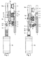
- shows a gate valve according to the invention and adjoining parts of a vacuum chamber, in part in exploded view,
- Fig. 2
- shows a partial sectional view of the gate valve and adjoining parts of the vacuum chamber as shown in
Fig. 1 , with the gate valve in a first state, and - Fig. 3
- shows a partial sectional view essentially like
Fig. 2 , with the gate valve in a second state. - The vacuum chamber which may be part of an assembly of vacuum chambers with a transport unit as shown in
US 5 693 238 A comprises (Fig. 1 ) a frame structure consisting of anouter frame 1 which surrounds a relatively large essentially oblong frame opening. The latter is filled by several also essentiallyoblong wall plates 2 which follow upon each other in a longitudinal direction which coincides with the vertical. Each of thewall plates 2 is provided with two slot-like openings 3 which are arranged one above the other and extend essentially over thewall plate 2 in a lateral direction which is perpendicular to the longitudinal direction and consequently horizontal. Through each of the openings 3 a compartment of the vacuum chamber is accessible. Eachopening 3 is surrounded by an O-ring 4 as an elastic sealing means. - The frame structure, i.e., the
outer frame 1 and thewall plates 2, define a substantially plane front facing away from the compartments which contains theopenings 3. At a distance from this front a gate valve for sealing theopenings 3 is arranged which comprises two rod-shaped carriers 5a,b which are each connected to theouter frame 1 by twolinks 6 at their upper ends and lower ends, respectively, i.e., at positions spaced from each other in the longitudinal direction. Thelinks 6 are connected to theouter frame 1 on the one hand and thecarrier 5a;b on the other hand pivotably aboutaxes 7; 8 parallel to the lateral direction. As for each one of thelinks 6 the distance between the twoaxes outer frame 1, thecarrier 5a;b and thelinks 6 connecting eachcarrier 5a;b to theouter frame 1 form a parallelogram suspension for thecarrier 5a;b, i.e., a mechanical guide means which causes its distance from the frame structure to vary while it remains parallel to the longitudinal direction whenever it is shifted longitudinally forward and backward over a switching interval. - The
carriers 5a,b carry a longitudinal row of bar-shaped sealing plates 9, onesealing plate 9 for each one of theopenings 3. Thesealing plates 9 extend in the lateral direction from thecarrier 5a to thecarrier 5b. Their opposite end portions are fixed to the first and to the latter, respectively. The surface of eachsealing plate 9 facing the front of the frame structure is essentially plane but slightly convex along the lateral direction. Eachsealing plate 9 is connected to eachcarrier 5a;b by a pair of compression springs 10 (s.Figs. 2, 3) such that thesealing plate 9 is displaceable in a direction away from the front against their elastic force. The displacement is limited by an adjustable stop, aspacer bolt 11 mounted on thecarrier 5a;b. - Two actuating members in the shape of actuating
rods 12a,b extend in the longitudinal direction, each guided by a succession ofplain bearing bushes 13 mounted to theouter frame 1. Each actuatingrod 12a;b is close to one of thecarriers 5a;b and connected to it at its lower and at its upper end and in the middle, respectively, by threelevers 14 which are appropriately spaced in the longitudinal direction. Eachlever 14 is pivotable with respect to thecarrier 5a;b about anaxis 15 and with respect to the actuatingrod 12a;b about anaxis 16 with both axes parallel to the lateral direction. Thecarrier 5a;b, thelevers 14 and theactuating rod 12a;b again form a paralleogram connection allowing the distance between the actuatingrod 12a;b and thecarrier 5a;b to vary in a direction perpendicular to the front while keeping them parallel. Each actuatingrod 12a;b is mounted on apiston 17 of apneumatic drive 18, which acts as a linear drive for the actuatingrod 12a;b. - In
Fig. 2 thesealing plates 9 are in an active position. Each of them presses against a plane front of one of thewall plates 2 which surrounds one of theopenings 3 and in particular against the O-ring 4, compressing the same and thereby keeping the opening 3 sealed. As the surfaces of thesealing plates 9 are slightly convex the latter are deformed somewhat when pressed against the front whereby the pressure is equalised and the sealing effect at the central parts of thesealing plate 9 which are removed from thecarriers 5a,b is improved. The compartments closed by thesealing plates 9 can then be evacuated and a vacuum processing step like PVD or plasma etching carried out therein. Depending on the construction details a relatively large pressure difference between the compartments and the outside is feasible. - To open the compartments the
pistons 17 are retracted, drawing the actuatingrods 12a,b downward. Via thelevers 14 thecarriers 5a,b are also forced downward and pulled away from the front. Due to the guidance by thelinks 6 the motion of thecarriers 5a,b follows a defined circular path, thecarriers 5a,b first moving thesealing plates 9 in parallel away from their active positions essentially perpendicularly and then more and more in a downward direction. When thecarriers 5a,b reach the opposite end of the switching interval, thesealing plates 9 are at inactive positions (Fig. 3 ) where the orthogonal projection of eachsealing plate 9 onto the front does not overlap with theopening 3 it covers in its active position. Thesealing plate 9 is completely out of the way and the compartment is easily accessible through theopening 3 in a direction perpendicular to the said plane. Insertion or retrieval of a substrate to be treated or having been treated, respectively, by a transport device can be carried out largely unencumbered by the gate valve. - For bringing the
sealing plates 9 back to their active positions where they seal theopenings 3 thepiston 17 is extended and the actuatingrods 12a,b, thelevers 14, and thecarriers 5a,b are each subjected to a reverse motion along the same trajectory. The final parallel motions of thesealing plates 9 into their active positions are essentially perpendicular to the frame whereby friction is avoided. -
1 outer frame 2 wall plate 3 opening 4 O- ring 5a, b carriers 6 link 7, 8 axes 9 sealing plate 10 compression spring 11 spacer bolt 12a,b actuating rods 13 plain bearing bush 14 lever 15, 16 axes 17 piston 18 pneumatic device
Claims (14)
- Gate valve for sealing at least one opening (3) in a substantially plane front of a frame structure, comprising at least one carrier (5a, 5b) extending in a longitudinal direction at a distance from the front and a sealing plate (9) for sealing the at least one opening (3) fixed to the said at least one carrier (5a, 5b), the carrier (5a, 5b) being movable forward and backward parallel to the longitudinal direction over a switching interval and the at least one sealing plate (9) being movable between an active position where it is in contact with a part of the front surrounding the opening (3), thereby sealing the latter, and an inactive position where it is at a distance from said front, leaving the opening (3) uncovered, and further comprising mechanical guide means with at least two parallel links (6) offset in the longitudinal direction, each link being connected to the carrier (5a; 5b) pivotably about an axis (8) extending in a lateral direction which is parallel to the front and perpendicular to the longitudinal direction, characterized in that each link (6) is also configured to be connected to the frame structure pivotably about an axis (7) extending in a lateral direction which is parallel to the front and perpendicular to the longitudinal direction, for the links (6) to guide the at least one carrier (5a; 5b) such that forward motion causes it to at the same time approach the front, the at least one sealing plate (9) assuming its active position, whereas backward motion causes it to move away from the front, the at least one sealing plate (9) assuming its inactive position.
- Gate valve according to claim 1, characterized in that in the inactive position the orthogonal projection of the at least one sealing plate (9) onto the front does not overlap with the at least one opening (3).
- Gate valve according to claim 1 or 2, characterized in that the guide means control the motion of the at least one carrier (5a; 5b) in such a way that the at least one sealing plate (9) approaches the active position in a direction essentially perpendicular to the front.
- Gate valve according to one of claims 1 to 3, characterized in that the at least one sealing plate (9) is connected to the at least one carrier (5a; 5b) in such a way that it is displaceable away from the front against an elastic force.
- Gate valve according to claim 4, characterized in that the range of displacement of the sealing plate is limited with the the limit being preferably adjustable.
- Gate valve according to one of claims 1 to 5, characterized in that it further comprises at least one actuating member extending in the longitudinal direction and movable parallel to the same forward and backward by an actuating means, the at least one actuating member being connected to at least one carrier (5a; 5b) in such a way that forward and backward motion of the actuating member causes motion of the carrier (5a; 5b) in the same direction in each case while allowing relative motion of the latter with respect to the actuating member in a direction perpendicular to the front.
- Gate valve according to claim 6, characterized in that the connection between the at least one actuating member and the at least one carrier (5a; 5b) comprises at least two parallel levers (14) offset in the longitudinal direction, each lever (14) being connected to the actuating member and to the carrier (5a; 5b) pivotably about axes (15, 16) parallel to the front and perpendicular to the longitudinal direction.
- Gate valve according to claim 6 or 7, characterized in that the at least one actuating member is in the shape of an actuating rod (12a; 12b) parallel to the longitudinal direction and the actuating means is a linear drive, preferably a pneumatic drive (18) comprising a piston (17) to which the actuating rod (12a; 12b) is connected.
- Gate valve according to one of claims 1 to 8, characterized in that it comprises a plurality of sealing plates (9) arranged in a row extending in the longitudinal direction, the individual sealing plates (9) each being bar-shaped and extending in a lateral direction parallel to the front and perpendicular to the longitudinal direction, the sealing plates (9) being suitable for closing openings (3) arranged in a row extending in the longitudinal direction where each opening (3) forms a slot extending in the lateral direction.
- Gate valve according to one of claims 1 to 9, characterized in that it comprises at least two carriers (5a, 5b) offset in a lateral direction parallel to the front and perpendicular to the longitudinal direction, with opposite end portions of the at least one sealing plate (9) being each fixed to one of the carriers (5a, 5b).
- Gate valve according to claim 9 or 10, characterized in that each sealing plate (9) exhibits a surface facing the front which is slightly convex along the lateral direction.
- Vacuum chamber comprising at least one gate valve according to one of claims 1 to 11 with each link (6) connected to the frame structure pivotably about an axis (7) extending in a lateral direction which is parallel to the front and perpendicular to the longitudinal direction and further comprising a frame structure with a substantially plane front which surrounds at least one opening (3) sealable by the at least one sealing plate (9) of the at least one gate valve.
- Vacuum chamber according to claim 12, characterized in that the at least one opening (3) is surrounded by an elastic sealing means mounted on the front which is compressed by the sealing plate (9) when the latter is in its active position.
- Vacuum chamber according to claim 12 or 13, characterized in that it comprises at least one stack of compartments where each compartment is accessible through one of the openings (3).
Applications Claiming Priority (2)
| Application Number | Priority Date | Filing Date | Title |
|---|---|---|---|
| US1539607P | 2007-12-20 | 2007-12-20 | |
| PCT/EP2008/010909 WO2009080304A1 (en) | 2007-12-20 | 2008-12-19 | Gate valve for a vacuum chamber and vacuum chamber |
Publications (2)
| Publication Number | Publication Date |
|---|---|
| EP2220412A1 EP2220412A1 (en) | 2010-08-25 |
| EP2220412B1 true EP2220412B1 (en) | 2013-05-15 |
Family
ID=40482007
Family Applications (1)
| Application Number | Title | Priority Date | Filing Date |
|---|---|---|---|
| EP08864682.3A Not-in-force EP2220412B1 (en) | 2007-12-20 | 2008-12-19 | Gate valve for a vacuum chamber and vacuum chamber |
Country Status (6)
| Country | Link |
|---|---|
| US (1) | US8448918B2 (en) |
| EP (1) | EP2220412B1 (en) |
| JP (1) | JP2011506774A (en) |
| CN (1) | CN101970918B (en) |
| TW (1) | TWI447319B (en) |
| WO (1) | WO2009080304A1 (en) |
Families Citing this family (20)
| Publication number | Priority date | Publication date | Assignee | Title |
|---|---|---|---|---|
| CN101994842B (en) * | 2010-12-02 | 2013-01-23 | 郴州浩伦生化助剂有限公司 | Reactor inserted plate type emptying valve |
| KR102160155B1 (en) * | 2013-03-14 | 2020-09-28 | 삼성디스플레이 주식회사 | Vacuum evaporating apparatus |
| CN103451616B (en) * | 2013-09-16 | 2016-07-27 | 南方科技大学 | Vacuum coating system and vacuum gate device thereof |
| EP2913573A1 (en) * | 2014-02-26 | 2015-09-02 | VAT Holding AG | Vacuum valve |
| TWI656293B (en) * | 2014-04-25 | 2019-04-11 | 瑞士商Vat控股股份有限公司 | Valve |
| JP6584829B2 (en) * | 2014-07-04 | 2019-10-02 | バット ホールディング アーゲー | valve |
| EP3012552B1 (en) * | 2014-10-21 | 2018-01-31 | Grundfos Holding A/S | Component for a compact heating system |
| US9470319B2 (en) * | 2015-01-26 | 2016-10-18 | King Lai Hygienic Materials Co., Ltd. | Gate valve with linkage structure |
| US10539253B2 (en) | 2015-03-05 | 2020-01-21 | Vat Holding Ag | Vacuum valve |
| EP3286465B1 (en) * | 2015-04-23 | 2020-04-01 | General Plasma, Inc. | Chamber valve |
| JP6633102B2 (en) * | 2016-01-28 | 2020-01-22 | 株式会社フジキン | Fluid control device and method of attaching / detaching gas line unit |
| JP6980454B2 (en) | 2017-08-17 | 2021-12-15 | 三菱重工業株式会社 | Composite material design method, composite material evaluation method and composite material |
| US10636629B2 (en) * | 2017-10-05 | 2020-04-28 | Applied Materials, Inc. | Split slit liner door |
| DE102017123231A1 (en) * | 2017-10-06 | 2019-04-11 | Aixtron Se | Closure element for closing a loading opening of an inner housing of a CVD reactor |
| CN108644171A (en) * | 2018-07-09 | 2018-10-12 | 江南阀门有限公司 | Crank-linkage type linkage mechanism |
| CN110701325A (en) * | 2019-10-17 | 2020-01-17 | 山东中能盛节能环保有限公司 | A compression seal valve |
| CN111271467B (en) * | 2020-01-20 | 2023-03-24 | 浙江冠正阀门股份有限公司 | Gate valve |
| ES2903028B2 (en) * | 2020-09-30 | 2023-01-24 | Delgado Francisco Campos | Mechanism for the tight closing of gates based on a system of connecting rods |
| JP7089245B1 (en) * | 2020-12-22 | 2022-06-22 | Smc株式会社 | Dual gate valve |
| CN114060545A (en) * | 2021-04-30 | 2022-02-18 | 四川九天真空科技股份有限公司 | Vacuum gate valve with antidetonation function |
Family Cites Families (18)
| Publication number | Priority date | Publication date | Assignee | Title |
|---|---|---|---|---|
| GB149855A (en) * | 1919-09-23 | 1920-08-26 | Camillo Vaccarezza | Improvements in or relating to valves |
| US1707125A (en) * | 1925-08-19 | 1929-03-26 | Loffler Stephan | High-pressure slide valve |
| GB257254A (en) * | 1925-08-19 | 1926-09-23 | Stephan Loeffler | An improved high-pressure stop valve |
| US2389947A (en) * | 1942-12-07 | 1945-11-27 | Manning Maxwell & Moore Inc | Valve |
| US2535525A (en) * | 1948-08-23 | 1950-12-26 | Fred E Wolfe | Gate valve |
| GB929192A (en) * | 1960-12-05 | 1963-06-19 | Cammell Laird & Company Shipbu | Improvements in or relating to valves for controlling the flow of steam, air, gases,or other fluids |
| US3119594A (en) * | 1961-02-17 | 1964-01-28 | Orbit Valve Co | Swing gate valve |
| FR1493479A (en) * | 1966-05-11 | 1967-09-01 | Commissariat Energie Atomique | Gate valve |
| US3510101A (en) * | 1967-02-16 | 1970-05-05 | Wilson A Burtis | High-pressure valve |
| US3632080A (en) * | 1969-05-12 | 1972-01-04 | Louis T King | Pressure-balanced flapper valve |
| JPS60222670A (en) * | 1985-03-27 | 1985-11-07 | Hitachi Ltd | gate valve |
| IL96766A (en) * | 1990-12-23 | 1994-07-31 | Feldinger Edgar | Control valve |
| CN2178310Y (en) * | 1993-10-11 | 1994-09-28 | 杨志远 | Bulkhead steel gate |
| JP2729916B2 (en) * | 1994-04-28 | 1998-03-18 | 大明金属工業株式会社 | Flat plug |
| CH692821A5 (en) * | 1998-02-04 | 2002-11-15 | Unaxis Trading Ag | Vacuum valve plate and vacuum chamber arrangement with such a status. |
| JP4225647B2 (en) * | 1999-09-08 | 2009-02-18 | キヤノンアネルバ株式会社 | Gate valve |
| ATE401517T1 (en) * | 2002-05-23 | 2008-08-15 | Friatec Ag | SHUT-OFF VALVE |
| CN2699075Y (en) * | 2004-03-19 | 2005-05-11 | 林德宽 | Sphere sealed gate valve |
-
2008
- 2008-12-15 TW TW097148735A patent/TWI447319B/en not_active IP Right Cessation
- 2008-12-19 EP EP08864682.3A patent/EP2220412B1/en not_active Not-in-force
- 2008-12-19 WO PCT/EP2008/010909 patent/WO2009080304A1/en not_active Ceased
- 2008-12-19 CN CN200880121748XA patent/CN101970918B/en not_active Expired - Fee Related
- 2008-12-19 US US12/808,337 patent/US8448918B2/en not_active Expired - Fee Related
- 2008-12-19 JP JP2010538478A patent/JP2011506774A/en active Pending
Also Published As
| Publication number | Publication date |
|---|---|
| US20100300920A1 (en) | 2010-12-02 |
| CN101970918A (en) | 2011-02-09 |
| TW200936924A (en) | 2009-09-01 |
| WO2009080304A1 (en) | 2009-07-02 |
| EP2220412A1 (en) | 2010-08-25 |
| US8448918B2 (en) | 2013-05-28 |
| CN101970918B (en) | 2013-06-26 |
| TWI447319B (en) | 2014-08-01 |
| JP2011506774A (en) | 2011-03-03 |
Similar Documents
| Publication | Publication Date | Title |
|---|---|---|
| US8448918B2 (en) | Gate valve for a vacuum chamber and vacuum chamber | |
| KR101540491B1 (en) | Vacuum valve | |
| US9404589B2 (en) | Non-sliding gate valve | |
| US8800956B2 (en) | Non-sliding gate valve | |
| CN102042420B (en) | Gate valve | |
| KR101814045B1 (en) | Gate valve | |
| EP1327090B1 (en) | Gate valve with delayed retraction of counter plate | |
| KR101426081B1 (en) | Vacuum valve | |
| TW201728846A (en) | Sealing device for vacuum sealing the opening in the wall | |
| KR20110073476A (en) | Vacuum valve | |
| EP1182387B1 (en) | Gate valve for semiconductor processing system | |
| JPWO2020225844A1 (en) | Gate valve | |
| KR20170120122A (en) | Vacuum valve | |
| KR101920414B1 (en) | Gate valve of Vacuum chamber apparatus | |
| US20150097306A1 (en) | Valve device for controlled introduction of a blowing medium | |
| JP2013175670A (en) | Substrate transport device and semiconductor manufacturing apparatus using the same | |
| JPH09324863A (en) | Non-sliding vacuum gate valve | |
| JP6735037B2 (en) | Gate valve device | |
| JP3323459B2 (en) | Gate valve | |
| JPH09310766A (en) | Non-sliding vacuum gate valve | |
| JP7537329B2 (en) | Gate valve with anti-vibration mechanism | |
| EP0436770B1 (en) | Non-sliding gate valve for high vacuum use | |
| CN211231654U (en) | Gate valve | |
| KR101252665B1 (en) | The gate valve of semiconductor production equipment | |
| KR101805475B1 (en) | Vaccum valve |
Legal Events
| Date | Code | Title | Description |
|---|---|---|---|
| PUAI | Public reference made under article 153(3) epc to a published international application that has entered the european phase |
Free format text: ORIGINAL CODE: 0009012 |
|
| 17P | Request for examination filed |
Effective date: 20100529 |
|
| AK | Designated contracting states |
Kind code of ref document: A1 Designated state(s): AT BE BG CH CY CZ DE DK EE ES FI FR GB GR HR HU IE IS IT LI LT LU LV MC MT NL NO PL PT RO SE SI SK TR |
|
| AX | Request for extension of the european patent |
Extension state: AL BA MK RS |
|
| DAX | Request for extension of the european patent (deleted) | ||
| RAP1 | Party data changed (applicant data changed or rights of an application transferred) |
Owner name: OERLIKON SOLAR AG, TRUEBBACH |
|
| GRAP | Despatch of communication of intention to grant a patent |
Free format text: ORIGINAL CODE: EPIDOSNIGR1 |
|
| GRAS | Grant fee paid |
Free format text: ORIGINAL CODE: EPIDOSNIGR3 |
|
| GRAA | (expected) grant |
Free format text: ORIGINAL CODE: 0009210 |
|
| AK | Designated contracting states |
Kind code of ref document: B1 Designated state(s): AT BE BG CH CY CZ DE DK EE ES FI FR GB GR HR HU IE IS IT LI LT LU LV MC MT NL NO PL PT RO SE SI SK TR |
|
| RAP1 | Party data changed (applicant data changed or rights of an application transferred) |
Owner name: TEL SOLAR AG |
|
| REG | Reference to a national code |
Ref country code: CH Ref legal event code: EP Ref country code: GB Ref legal event code: FG4D |
|
| REG | Reference to a national code |
Ref country code: AT Ref legal event code: REF Ref document number: 612341 Country of ref document: AT Kind code of ref document: T Effective date: 20130615 |
|
| REG | Reference to a national code |
Ref country code: IE Ref legal event code: FG4D |
|
| REG | Reference to a national code |
Ref country code: DE Ref legal event code: R096 Ref document number: 602008024656 Country of ref document: DE Effective date: 20130711 |
|
| REG | Reference to a national code |
Ref country code: AT Ref legal event code: MK05 Ref document number: 612341 Country of ref document: AT Kind code of ref document: T Effective date: 20130515 |
|
| REG | Reference to a national code |
Ref country code: LT Ref legal event code: MG4D |
|
| REG | Reference to a national code |
Ref country code: NL Ref legal event code: VDEP Effective date: 20130515 |
|
| PG25 | Lapsed in a contracting state [announced via postgrant information from national office to epo] |
Ref country code: ES Free format text: LAPSE BECAUSE OF FAILURE TO SUBMIT A TRANSLATION OF THE DESCRIPTION OR TO PAY THE FEE WITHIN THE PRESCRIBED TIME-LIMIT Effective date: 20130826 Ref country code: SI Free format text: LAPSE BECAUSE OF FAILURE TO SUBMIT A TRANSLATION OF THE DESCRIPTION OR TO PAY THE FEE WITHIN THE PRESCRIBED TIME-LIMIT Effective date: 20130515 Ref country code: SE Free format text: LAPSE BECAUSE OF FAILURE TO SUBMIT A TRANSLATION OF THE DESCRIPTION OR TO PAY THE FEE WITHIN THE PRESCRIBED TIME-LIMIT Effective date: 20130515 Ref country code: NO Free format text: LAPSE BECAUSE OF FAILURE TO SUBMIT A TRANSLATION OF THE DESCRIPTION OR TO PAY THE FEE WITHIN THE PRESCRIBED TIME-LIMIT Effective date: 20130815 Ref country code: GR Free format text: LAPSE BECAUSE OF FAILURE TO SUBMIT A TRANSLATION OF THE DESCRIPTION OR TO PAY THE FEE WITHIN THE PRESCRIBED TIME-LIMIT Effective date: 20130816 Ref country code: FI Free format text: LAPSE BECAUSE OF FAILURE TO SUBMIT A TRANSLATION OF THE DESCRIPTION OR TO PAY THE FEE WITHIN THE PRESCRIBED TIME-LIMIT Effective date: 20130515 Ref country code: PT Free format text: LAPSE BECAUSE OF FAILURE TO SUBMIT A TRANSLATION OF THE DESCRIPTION OR TO PAY THE FEE WITHIN THE PRESCRIBED TIME-LIMIT Effective date: 20130916 Ref country code: AT Free format text: LAPSE BECAUSE OF FAILURE TO SUBMIT A TRANSLATION OF THE DESCRIPTION OR TO PAY THE FEE WITHIN THE PRESCRIBED TIME-LIMIT Effective date: 20130515 Ref country code: IS Free format text: LAPSE BECAUSE OF FAILURE TO SUBMIT A TRANSLATION OF THE DESCRIPTION OR TO PAY THE FEE WITHIN THE PRESCRIBED TIME-LIMIT Effective date: 20130915 Ref country code: LT Free format text: LAPSE BECAUSE OF FAILURE TO SUBMIT A TRANSLATION OF THE DESCRIPTION OR TO PAY THE FEE WITHIN THE PRESCRIBED TIME-LIMIT Effective date: 20130515 |
|
| PG25 | Lapsed in a contracting state [announced via postgrant information from national office to epo] |
Ref country code: PL Free format text: LAPSE BECAUSE OF FAILURE TO SUBMIT A TRANSLATION OF THE DESCRIPTION OR TO PAY THE FEE WITHIN THE PRESCRIBED TIME-LIMIT Effective date: 20130515 Ref country code: HR Free format text: LAPSE BECAUSE OF FAILURE TO SUBMIT A TRANSLATION OF THE DESCRIPTION OR TO PAY THE FEE WITHIN THE PRESCRIBED TIME-LIMIT Effective date: 20130515 Ref country code: BG Free format text: LAPSE BECAUSE OF FAILURE TO SUBMIT A TRANSLATION OF THE DESCRIPTION OR TO PAY THE FEE WITHIN THE PRESCRIBED TIME-LIMIT Effective date: 20130815 |
|
| PG25 | Lapsed in a contracting state [announced via postgrant information from national office to epo] |
Ref country code: LV Free format text: LAPSE BECAUSE OF FAILURE TO SUBMIT A TRANSLATION OF THE DESCRIPTION OR TO PAY THE FEE WITHIN THE PRESCRIBED TIME-LIMIT Effective date: 20130515 |
|
| PG25 | Lapsed in a contracting state [announced via postgrant information from national office to epo] |
Ref country code: EE Free format text: LAPSE BECAUSE OF FAILURE TO SUBMIT A TRANSLATION OF THE DESCRIPTION OR TO PAY THE FEE WITHIN THE PRESCRIBED TIME-LIMIT Effective date: 20130515 Ref country code: CZ Free format text: LAPSE BECAUSE OF FAILURE TO SUBMIT A TRANSLATION OF THE DESCRIPTION OR TO PAY THE FEE WITHIN THE PRESCRIBED TIME-LIMIT Effective date: 20130515 Ref country code: DK Free format text: LAPSE BECAUSE OF FAILURE TO SUBMIT A TRANSLATION OF THE DESCRIPTION OR TO PAY THE FEE WITHIN THE PRESCRIBED TIME-LIMIT Effective date: 20130515 Ref country code: SK Free format text: LAPSE BECAUSE OF FAILURE TO SUBMIT A TRANSLATION OF THE DESCRIPTION OR TO PAY THE FEE WITHIN THE PRESCRIBED TIME-LIMIT Effective date: 20130515 Ref country code: BE Free format text: LAPSE BECAUSE OF FAILURE TO SUBMIT A TRANSLATION OF THE DESCRIPTION OR TO PAY THE FEE WITHIN THE PRESCRIBED TIME-LIMIT Effective date: 20130515 |
|
| PG25 | Lapsed in a contracting state [announced via postgrant information from national office to epo] |
Ref country code: IT Free format text: LAPSE BECAUSE OF FAILURE TO SUBMIT A TRANSLATION OF THE DESCRIPTION OR TO PAY THE FEE WITHIN THE PRESCRIBED TIME-LIMIT Effective date: 20130515 Ref country code: NL Free format text: LAPSE BECAUSE OF FAILURE TO SUBMIT A TRANSLATION OF THE DESCRIPTION OR TO PAY THE FEE WITHIN THE PRESCRIBED TIME-LIMIT Effective date: 20130515 Ref country code: RO Free format text: LAPSE BECAUSE OF FAILURE TO SUBMIT A TRANSLATION OF THE DESCRIPTION OR TO PAY THE FEE WITHIN THE PRESCRIBED TIME-LIMIT Effective date: 20130515 |
|
| PLBE | No opposition filed within time limit |
Free format text: ORIGINAL CODE: 0009261 |
|
| STAA | Information on the status of an ep patent application or granted ep patent |
Free format text: STATUS: NO OPPOSITION FILED WITHIN TIME LIMIT |
|
| 26N | No opposition filed |
Effective date: 20140218 |
|
| REG | Reference to a national code |
Ref country code: DE Ref legal event code: R097 Ref document number: 602008024656 Country of ref document: DE Effective date: 20140218 |
|
| REG | Reference to a national code |
Ref country code: CH Ref legal event code: PL |
|
| GBPC | Gb: european patent ceased through non-payment of renewal fee |
Effective date: 20131219 |
|
| PG25 | Lapsed in a contracting state [announced via postgrant information from national office to epo] |
Ref country code: LU Free format text: LAPSE BECAUSE OF FAILURE TO SUBMIT A TRANSLATION OF THE DESCRIPTION OR TO PAY THE FEE WITHIN THE PRESCRIBED TIME-LIMIT Effective date: 20131219 Ref country code: MC Free format text: LAPSE BECAUSE OF FAILURE TO SUBMIT A TRANSLATION OF THE DESCRIPTION OR TO PAY THE FEE WITHIN THE PRESCRIBED TIME-LIMIT Effective date: 20130515 |
|
| REG | Reference to a national code |
Ref country code: IE Ref legal event code: MM4A |
|
| REG | Reference to a national code |
Ref country code: FR Ref legal event code: ST Effective date: 20140829 |
|
| PG25 | Lapsed in a contracting state [announced via postgrant information from national office to epo] |
Ref country code: IE Free format text: LAPSE BECAUSE OF NON-PAYMENT OF DUE FEES Effective date: 20131219 Ref country code: CH Free format text: LAPSE BECAUSE OF NON-PAYMENT OF DUE FEES Effective date: 20131231 Ref country code: LI Free format text: LAPSE BECAUSE OF NON-PAYMENT OF DUE FEES Effective date: 20131231 |
|
| PG25 | Lapsed in a contracting state [announced via postgrant information from national office to epo] |
Ref country code: FR Free format text: LAPSE BECAUSE OF NON-PAYMENT OF DUE FEES Effective date: 20131231 Ref country code: GB Free format text: LAPSE BECAUSE OF NON-PAYMENT OF DUE FEES Effective date: 20131219 |
|
| PG25 | Lapsed in a contracting state [announced via postgrant information from national office to epo] |
Ref country code: TR Free format text: LAPSE BECAUSE OF FAILURE TO SUBMIT A TRANSLATION OF THE DESCRIPTION OR TO PAY THE FEE WITHIN THE PRESCRIBED TIME-LIMIT Effective date: 20130515 Ref country code: CY Free format text: LAPSE BECAUSE OF FAILURE TO SUBMIT A TRANSLATION OF THE DESCRIPTION OR TO PAY THE FEE WITHIN THE PRESCRIBED TIME-LIMIT Effective date: 20130515 |
|
| PG25 | Lapsed in a contracting state [announced via postgrant information from national office to epo] |
Ref country code: HU Free format text: LAPSE BECAUSE OF FAILURE TO SUBMIT A TRANSLATION OF THE DESCRIPTION OR TO PAY THE FEE WITHIN THE PRESCRIBED TIME-LIMIT; INVALID AB INITIO Effective date: 20081219 |
|
| PG25 | Lapsed in a contracting state [announced via postgrant information from national office to epo] |
Ref country code: MT Free format text: LAPSE BECAUSE OF FAILURE TO SUBMIT A TRANSLATION OF THE DESCRIPTION OR TO PAY THE FEE WITHIN THE PRESCRIBED TIME-LIMIT Effective date: 20130515 |
|
| REG | Reference to a national code |
Ref country code: DE Ref legal event code: R081 Ref document number: 602008024656 Country of ref document: DE Owner name: EVATEC AG, CH Free format text: FORMER OWNER: TEL SOLAR AG IN LIQUIDATION, TRUEBBACH, CH Ref country code: DE Ref legal event code: R081 Ref document number: 602008024656 Country of ref document: DE Owner name: EVATEC AG, CH Free format text: FORMER OWNER: TEL SOLAR AG, TRUEBBACH, CH Ref country code: DE Ref legal event code: R082 Ref document number: 602008024656 Country of ref document: DE Representative=s name: EISENFUEHR SPEISER PATENTANWAELTE RECHTSANWAEL, DE |
|
| REG | Reference to a national code |
Ref country code: DE Ref legal event code: R082 Ref document number: 602008024656 Country of ref document: DE |
|
| P01 | Opt-out of the competence of the unified patent court (upc) registered |
Effective date: 20230526 |
|
| PGFP | Annual fee paid to national office [announced via postgrant information from national office to epo] |
Ref country code: DE Payment date: 20231031 Year of fee payment: 16 |
|
| REG | Reference to a national code |
Ref country code: DE Ref legal event code: R119 Ref document number: 602008024656 Country of ref document: DE |
|
| PG25 | Lapsed in a contracting state [announced via postgrant information from national office to epo] |
Ref country code: DE Free format text: LAPSE BECAUSE OF NON-PAYMENT OF DUE FEES Effective date: 20250701 |