EP2219401B1 - System und Verfahren zum effizienten Ausfüllen einer Zugangspunktdatenbank - Google Patents
System und Verfahren zum effizienten Ausfüllen einer Zugangspunktdatenbank Download PDFInfo
- Publication number
- EP2219401B1 EP2219401B1 EP10151910.6A EP10151910A EP2219401B1 EP 2219401 B1 EP2219401 B1 EP 2219401B1 EP 10151910 A EP10151910 A EP 10151910A EP 2219401 B1 EP2219401 B1 EP 2219401B1
- Authority
- EP
- European Patent Office
- Prior art keywords
- access point
- scan data
- mobile devices
- location
- access
- Prior art date
- Legal status (The legal status is an assumption and is not a legal conclusion. Google has not performed a legal analysis and makes no representation as to the accuracy of the status listed.)
- Not-in-force
Links
Images


Classifications
-
- H—ELECTRICITY
- H04—ELECTRIC COMMUNICATION TECHNIQUE
- H04W—WIRELESS COMMUNICATION NETWORKS
- H04W64/00—Locating users or terminals or network equipment for network management purposes, e.g. mobility management
-
- H—ELECTRICITY
- H04—ELECTRIC COMMUNICATION TECHNIQUE
- H04W—WIRELESS COMMUNICATION NETWORKS
- H04W24/00—Supervisory, monitoring or testing arrangements
- H04W24/02—Arrangements for optimising operational condition
-
- H—ELECTRICITY
- H04—ELECTRIC COMMUNICATION TECHNIQUE
- H04W—WIRELESS COMMUNICATION NETWORKS
- H04W48/00—Access restriction; Network selection; Access point selection
- H04W48/16—Discovering, processing access restriction or access information
-
- H—ELECTRICITY
- H04—ELECTRIC COMMUNICATION TECHNIQUE
- H04W—WIRELESS COMMUNICATION NETWORKS
- H04W64/00—Locating users or terminals or network equipment for network management purposes, e.g. mobility management
- H04W64/003—Locating users or terminals or network equipment for network management purposes, e.g. mobility management locating network equipment
-
- H—ELECTRICITY
- H04—ELECTRIC COMMUNICATION TECHNIQUE
- H04W—WIRELESS COMMUNICATION NETWORKS
- H04W88/00—Devices specially adapted for wireless communication networks, e.g. terminals, base stations or access point devices
- H04W88/08—Access point devices
Definitions
- This invention relates generally to a system and method for efficiently populating an access point database.
- US 2006/0240840A discloses a prior art system for providing locations of Wifi Access Points.
- WO2007/056738A describes a prior art system that provides a database of access points.
- mobile devices in an electronic network initially determine their physical location by utilizing any appropriate techniques. For example, the mobile devices may receive transmitted signals from a global positioning system (GPS), and may then utilize the corresponding GPS signals to determine their respective physical locations. The mobile devices each transmit their particular location coordinates to a location server in the electronic network.
- GPS global positioning system
- the mobile devices automatically perform a wireless scanning procedure to detect and store any appropriate access point scan data from access point signals transmitted from one or more access points that are distributed throughout the electronic network.
- the captured access point scan data may include, but is not limited to, access point identifiers and access point signal strengths corresponding to respective access points.
- the mobile devices then transmit the captured access point scan data to the location server by utilizing any appropriate techniques.
- the location server then updates the access point database with any new or different access point locations that are discovered as a result of the foregoing access point location procedure. Finally, the location server may transmit the updated access point database to the mobile devices for use in calculating physical locations of the respective mobile devices with respect to the access points. For at least the foregoing reasons, the present invention therefore provides an improved system and method for efficiently populating an access point database.
- the invention relates to techniques for utilizing mobile electronic devices.
- the present invention relates to an improvement in the effective utilization of mobile electronic devices.
- the following description is presented to enable one of ordinary skill in the art to make and use the invention, and is provided in the context of a patent application and its requirements.
- Various modifications to the disclosed embodiments will be readily apparent to those skilled in the art, and the generic principles herein may be applied to other embodiments.
- the present invention is not intended to be limited to the embodiments shown, but is to be accorded the widest scope consistent with the principles and features described herein.
- the present invention is described herein as a system and method for populating an access point database, and includes a network of access points that are implemented to transmit access point signals by utilizing a wireless broadcasting procedure.
- One or more mobile devices are then configured to wirelessly receive and analyze the access point signals to produce access point scan data corresponding to the access points.
- a location server receives and analyzes the access point scan data to determine specific access point locations for the access points. The location server may then utilize the calculated access point locations to populate the access point database.
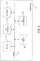
- electronic system 110 may include, but is not limited to, one or more mobile device(s) 114, a plurality of satellites 118, a plurality of base stations 122, a location server 126, and a plurality of access points 130.
- electronic system 110 may be implemented using various components and configurations in addition to, or instead of, those components and configurations discussed in conjunction with the FIG. 1 embodiment.
- FIG. 1 embodiment is implemented with one or more mobile device(s) 114, four satellites 118, two base stations 122, one location server 126, and three access points 130.
- electronic network 110 may be implemented to include any desired number of the mobile devices 114, satellites 118, base stations 122, location servers 126, and access points 130.
- mobile device(s) 114 may be implemented as any type of electronic device for which a current physical location may be determined and conveyed to a device user or other appropriate entity.
- mobile devices 114 may include, but are not limited to, a laptop computer device, a personal digital assistant (PDA), or a cellular telephone. Additional details regarding the implementation and utilization of mobile device 114 are further discussed below in conjunction with FIGS. 3-4 .
- satellites 130 include, but are not limited to, a satellite A 118(a), a satellite B 118(b), a satellite C 118(c), and a satellite D 118(d) that are implemented by utilizing any appropriate technologies to perform any desired functions or operations.
- satellites 118 may be implemented as part of a known or enhanced global positioning system (GPS).
- GPS global positioning system
- satellites 118 typically transmit respective satellite beacon signals that mobile devices 114 may receive and analyze using known location calculation procedures (such as trilateralization and/or triangulation) to potentially determine current physical locations (such as longitude, latitude, and altitude information) for mobile devices 114.
- mobile devices 114 may be unable to receive satellite beacon signals from a sufficient number of the satellites 130 to successfully perform the location calculation procedures.
- mobile devices 114 may be inside a building or other structure that prevents some or all of the satellite beacon signals from reaching mobile devices 114.
- one or more of the satellite beacon signals may have insufficient signal quality characteristics.
- the FIG. 1 embodiment may include a base station A 122(a) and a base station B 122(b) that are both implemented as terrestrial devices that transmit pilot signals that may be received by mobile devices 114.
- mobile devices 114 may analyze the pilot signals from base stations 122 using similar location calculation procedures potentially determine the current physical locations of mobile devices 114.
- base stations 122 may be implemented by utilizing any appropriate technologies to perform any desired functions or operations.
- base stations 122 may be implemented as part of a known or enhanced wireless wide-area network (WWAN) system by utilizing any appropriate technologies.
- WWAN wireless wide-area network
- satellites 118 and base stations 122 may be implemented as part of a known or enhanced assisted global-positioning system (AGPS) network.
- electronic network 110 may also include a location server 126 that mobile devices 114 utilize to perform various types of calculations or processing functions to thereby conserve processing resources for mobile devices 114.
- the FIG. 1 embodiment advantageously includes access points 130 that are implemented as terrestrial devices that transmit access-point beacon signals to mobile devices 114.
- access points 130 are implemented as terrestrial devices that transmit access-point beacon signals to mobile devices 114.
- mobile devices 114 may also analyze the access-point beacon signals using similar location calculation procedures to more accurately and effectively determine the current physical location of mobile devices 114.
- access points 130 include, but are not limited to, an access point A 130(a), an access point B 130(b), and an access point C 130(c) that may be implemented by utilizing any appropriate technologies to perform any desired functions or operations.
- access points 130 may be implemented as part of a known or enhanced wireless local-area network (WLAN) system using any appropriate technologies.
- WLAN wireless local-area network
- access points 130 may be implemented according to WLAN standards that include, but are not limited to, any of the known 802.11 WLAN standards (such as 802.11a. 802.11b, 802.11g, and 802.11n).
- access points 130 are implemented as publicly-deployed WiFi "hotspots" or other similar WLAN nodes/systems
- the widespread presence of such WLAN networks provides a ready availability of pre-existing potential access points 130 at many public locations.
- an access point (AP) database (see FIG. 7 ) is typically utilized to specifically indicate physical coordinates for each access point 130.
- access points 130 have easily changeable locations, and because access points 130 may be added or removed at any time, one traditional method of populating and maintaining a AP database is to employ one or more individuals to drive around an area with a WiFi scanner device to measure and physically locate any available access points 130. This process is time-consuming and expensive. In addition, any resulting AP database may be inaccurate because of changes that have occurred since the last scanning process.
- the present invention therefore proposes to advantageously utilize WiFi functionality of the mobile devices 114 to automatically and transparently scan on an ongoing basis for access point signals transmitted from the access points 130.
- the mobile devices 114 may then automatically transmit the AP measurement data to location server 126 or another appropriate entity for populating and updating the AP database. Additional details regarding the efficient updating of an access point database are further discussed below in conjunction with FIGS. 3-9B .
- access point 130 may include, but is not limited to, an AP central processing unit (CPU) 212, an AP transceiver 214, an AP display 216, an AP memory 220, and one or more AP input/output interfaces (I/O interfaces) 224. Selected ones of the foregoing components of access point 130 may be coupled to, and communicate through, an AP bus 228. In alternate embodiments, access point 130 may be implemented using various components and configurations in addition to, or instead of, certain of components and configurations discussed in conjunction with the FIG. 2 embodiment.
- AP CPU 212 may be implemented to include any appropriate and compatible microprocessor device that preferably executes software instructions to thereby control and manage the operation of access point 130.
- AP memory 220 may be implemented to include any combination of desired storage devices, including, but not limited to, read-only memory (ROM), random-access memory (RAM), and various types of non-volatile memory, such as floppy disks, flash memory, or hard disks.
- AP I/O interfaces 224 may preferably include one or more input and/or output interfaces to receive and/or transmit any required types of information for access point 130.
- access point 130 may utilize AP I/O interfaces 224 to bi-directionally communicate with any desired type of external entities to receive or send electronic information by utilizing any appropriate and effective techniques.
- mobile device 114 may include, but is not limited to, an MD central processing unit (CPU) 312, an MD transceiver 314, an MD display 316, an MD memory 320, and one or more MD input/output interfaces (I/O interfaces) 324. Selected ones of the foregoing components of mobile device 114 may be coupled to, and communicate through, an MD bus 328. In alternate embodiments, mobile device 114 may be implemented using components and configurations in addition to, or instead of, certain of those components and configurations discussed in conjunction with the FIG. 3 embodiment.
- MD CPU 312 may be implemented to include any appropriate and compatible microprocessor device that preferably executes software instructions to thereby control and manage the operation of mobile device 114.
- MD memory 320 may be implemented to include any combination of desired storage devices, including, but not limited to, read-only memory (ROM), random-access memory (RAM), and various types of non-volatile memory, such as floppy disks, flash memory, or hard disks. Additional details regarding the implementation and utilization of MD memory 320 are further discussed below in conjunction with FIG. 4 .
- MD I/O interfaces 324 may preferably include one or more input and/or output interfaces to receive and/or transmit any required types of information for mobile device 114.
- mobile device 114 may utilize MD I/O interfaces 324 to bi-directionally communicate with any desired type of external entities to receive or send electronic information by utilizing any appropriate and effective techniques.
- mobile device 114 may utilize MD display 316 for displaying any desired type of information by utilizing any effective type of display technologies.
- MD transceiver 314 may include any appropriate means for bi-directionally transferring (transmitting and/or receiving) electronic information between mobile device 114 and other devices by utilizing wireless communication techniques.
- MD transceiver 314 may include, but is not limited to, a satellite transceiver for communicating with satellites 118, a base station transceiver for communicating with base stations 126, and an access-point transceiver for communicating with access points 130. Additional details regarding the implementation and utilization of mobile device 114 are further discussed below in conjunction with FIGS. 4-9B .
- MD memory 320 includes, but is not limited to, an application program 412, a location detector 416, a satellite module 420, a base station module 424, an access point module 428, an access point (AP) database 432, a WiFi scan controller 436, and WiFi scan data 440.
- MD memory 320 may include components and functionalities in addition to, or instead of, certain of those components and functionalities discussed in conjunction with the FIG. 4 embodiment.
- application program 412 may include program instructions that are preferably executed by MD CPU 312 ( FIG. 3 ) to perform various functions and operations for mobile device 114.
- the particular nature and functionality of application program 412 typically varies depending upon factors such as the specific type and particular functionality of the corresponding mobile device 114.
- location detector 412 may be utilized to coordinate and manage enhanced mobile-device location procedures to determine a current physical location of a mobile device 114 by utilizing any effective techniques.
- location detector 412 may utilize information in AP database 432 to perform device location procedures.
- location server 126 FIG. 1
- location server 126 may also have a software module similar to location detector 412 to remotely perform certain required processing functions.
- satellite module 424 may be utilized to manage communications with satellites 118 ( FIG. 1 ).
- base station module 424 may be utilized to manage communications with base stations 122 ( FIG. 1 )
- access point module 428 may be utilized to manage communications with access points 130 ( FIG. 1 ).
- a WiFi scan controller 436 automatically performs access point (AP) scanning procedures to measure relevant characteristics of transmissions from one or more access points 130.
- WiFi scan controller then stores any collected information as WiFi scan data 440.
- WiFi scan data 440 may include any types of measurements, data, or other information relating to respective ones of the access points 130 ( FIG. 1 ). Examples of such information include, but are not limited to, presence/availability of access-point beacon signals, signal strengths, signal-to-noise values, signal quality characteristics, signal delays, etc.
- the location detector 416, WiFi scan controller 436, and the various modules 420, 424, and 428 are disclosed and discussed as being implemented as software. However, in alternate embodiments, some or all of these functions may be performed by appropriate electronic hardware circuits that are configured for performing various functions that are equivalent to those functions of the software modules discussed herein. The implementation and utilization of WiFi scan controller are further discussed below in conjunction with FIGS. 5-9B .
- location server 126 includes, but is not limited to, a server CPU 514, a server memory 518, a server display 538, and I/O interface(s) 540.
- location server 126 may be implemented using components and configurations in addition to, or instead of, certain of those components and configurations discussed in conjunction with the FIG. 5 embodiment.
- server CPU 514 may be implemented to include any appropriate and compatible microprocessor device that preferably executes software instructions to thereby control and manage the operation of location server 126.
- server memory 518 may be implemented to include any combination of desired storage devices, including, but not limited to, read-only memory (ROM), random-access memory (RAM), and various types of non-volatile memory, such as floppy disks, flash memory, or hard disks. Additional details regarding the implementation and utilization of server memory 518 are further discussed below in conjunction with FIG. 6 .
- I/O interfaces 540 may preferably include one or more input and/or output interfaces to receive and/or transmit any required types of information for location server 126.
- location server 126 may utilize I/O interfaces 540 to bi-directionally communicate with any desired type of external entities to receive or send electronic information by utilizing any appropriate and effective techniques.
- location server 126 may utilize server display 538 for displaying any desired type of information by utilizing any effective type of display technologies. Additional details regarding the implementation and utilization of location server 126 are further discussed below in conjunction with FIGS. 6-9B .
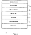
- server memory 518 includes, but is not limited to, a server application 622, an AP location calculator 626, WiFi scan data 440, an AP database 432, a communication module 638, and miscellaneous information 654.
- server memory 518 may include components and functionalities in addition to, or instead of, certain of those components and functionalities discussed in conjunction with the FIG. 6 embodiment.
- location server 126 uses AP location calculator 626 to analyze appropriate information from WiFi scan data 440 to determine specific locations for one or more access points 130 ( FIG. 1 ) in any effective manner.
- AP location calculator 626 may utilize WiFi scan data 440 to calculate location coordinates for a given access point 130 by performing basic triangulation calculations, as discussed below in conjunction with FIG. 8 .
- more complex calculation techniques may be utilized to build statistical models that represent the location of one or more access points 130 by utilizing a greater number of AP measurements from mobile devices 114.
- AP location calculator 626 may populate and update AP database 432 with newly calculated locations of one or more access points 130.
- AP database 432 is further discussed below in conjunction with FIG. 7 .
- Location server 126 may utilize communication module 638 to conduct bi-directional communications with any external entity, including but not limited to, mobile devices 114.
- Miscellaneous information 654 may include any other information or data for use by location server 126. The utilization of location server 126 is further discussed below in conjunction with FIGS. 7-9B .
- FIG. 7 a block diagram for one embodiment of the AP database 432 of FIGS. 4 and 6 is shown, in accordance with the present invention.
- the FIG. 7 embodiment is presented for purposes of illustration, and in alternate embodiments, AP database 432 may include components and functionalities in addition to, or instead of, certain of those components and functionalities discussed in conjunction with the FIG. 7 embodiment.
- AP database 432 includes, but is not limited to, a series of entries 740 that each corresponds to a different access point 130 in the WiFi network.
- each entry 740 includes, but is not limited to, an AP identifier that specifically identifies a corresponding one of the access points 130.
- Each AP identifier is associated with corresponding AP coordinates that indicate a physical location for the particular access point 130.
- the AP coordinates may include any desired location information, including but not limited to, a device latitude, a device longitude, and a device altitude.
- the population of AP database 432 is further discussed below in conjunction with FIGS. 8-9B .
- FIG. 8 a diagram illustrating an access point location procedure is shown, in accordance with one embodiment of the present invention.
- the FIG. 8 embodiment is presented for purposes of illustration, and in alternate embodiments, locating access points 130 may include techniques and functionalities in addition to, or instead of, certain of those techniques and functionalities discussed in conjunction with the FIG. 8 embodiment.
- the location of access point (AP) 130 is unknown.
- Three mobile devices 114 (D1 114(a), D2 114(b), and D3 114(c)), whose locations are known by utilizing any effective means, are located in relative proximity to access point 130.
- a single mobile device 114 may be utilized by simply moving the single device 114 to three (or more) different locations.
- a greater number of mobile devices 114 may also be utilized.
- device 114(a) scans for, and detects, a WiFi signal from access point 130.
- device 114(a) then records an AP identifier and a signal strength for the scanned access point 130 as WiFi scan data 440.
- Device 114(a) wirelessly transmits the WiFi scan data 440 to a location server 126 (see FIG. 1 ) or other appropriate entity.
- the location server 126 evaluates the signal strength from the received WiFi scan data 440 to create a location circle 818 with a radius R1 822 that represents the distance from device 114(a) to the scanned access point 130. In other words, the target access point 130 lies somewhere on location circle 818.
- device 114(b) similarly scans for, and detects, a WiFi signal from access point 130.
- device 114(b) then records an AP identifier and a signal strength for the scanned access point 130 as WiFi scan data 440.
- Device 114(b) wirelessly transmits the WiFi scan data 440 to location server 126 or other appropriate entity.
- the location server 126 evaluates the signal strength from the received WiFi scan data 440 to create a location circle 824 with a radius R2 828 that represents the distance from device 114(b) to the scanned access point 130. In other words, the target access point 130 lies somewhere on location circle 824.
- device 114(c) also scans for, and detects, a WiFi signal from access point 130.
- device 114(c) then records an AP identifier and a signal strength for the scanned access point 130 as WiFi scan data 440.
- Device 114(c) wirelessly transmits the WiFi scan data 440 to location server 126 or other appropriate entity.
- the location server 126 evaluates the signal strength from the received WiFi scan data 440 to create a location circle 832 with a radius R3 836 that represents the distance from device 114(c) to the scanned access point 130. In other words, the target access point 130 lies somewhere on location circle 832.
- an AP location calculator 626 may then evaluate all the received WiFi scan data 440 from the three mobile devices 114 to determine a specific location for access point 130 by utilizing any effective calculation techniques.
- the location of access point 130 may be defined as the point at which all three location circles 818, 824, and 832 intersect, or as the only point that may be triangulated by utilizing the three radius vectors 822, 824, and 836.
- location server 126 may utilize that location information to update the AP database 432, as discussed above. Additional techniques for updating AP database 432 are discussed below in conjunction with FIG. 9 .
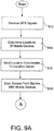
- FIGS. 9A-9B a flowchart of method steps for efficiently populating an access point database is shown, in accordance with one embodiment of the present invention.
- the example of FIGS. 9A-9B is presented for purposes of illustration, and in alternate embodiments, the present invention may utilize steps and sequences other than those step and sequences discussed in conjunction with the embodiment of FIGS. 9A-9B .
- step 912 mobile devices 114 in an electronic network initially determine their physical location by utilizing any appropriate techniques.
- the mobile devices 114 may receive transmitted signals from a global positioning system (GPS), and in step 914, the mobiles devices 114 may utilize the corresponding GPS signals to determine their respective physical locations.
- the mobile devices 114 each transmit their particular location coordinates to a location server 126 in the electronic network.
- GPS global positioning system
- the mobile devices 114 automatically perform a wireless scanning procedure to detect and store any appropriate AP scan data 440 from access point signals transmitted from one or more access points 130 that are distributed throughout the electronic network.
- the captured AP scan data 440 may include, but is not limited to, access point identifiers and access point signal strengths corresponding to respective access points 130.
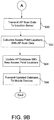
- the FIG. 9A process then advances to step 920 of FIG. 9B through connecting letter "A.”
- step 920 the mobile devices 114 transmit the captured AP scan data 440 to the location server 126 by utilizing any appropriate techniques.
- an AP location calculator 626 of the location server 126 utilizes the received AP scan data 440 to perform an access point location procedure.
- AP location calculator 626 utilizes the received AP scan data 440 to calculate specific access point locations for one or more access points 130 in the electronic network by utilizing any appropriate and effective location calculation techniques.
- step 924 the location server 126 updates an access point database 432 with any new or different access point locations that are discovered as a result of the foregoing access point location procedure.
- step 926 the location server 126 transmits the updated access point database 432 to the mobile devices 114 for use in calculating physical locations of the respective mobile devices 114 with respect to the access points 130.
- the present invention thus provides an improved system and method for efficiently populating an access point database.
Landscapes
- Engineering & Computer Science (AREA)
- Computer Networks & Wireless Communication (AREA)
- Signal Processing (AREA)
- Mobile Radio Communication Systems (AREA)
- Position Fixing By Use Of Radio Waves (AREA)
Claims (7)
- System (110) zum Besiedeln einer Zugangspunkt-Datenbank, umfassend:Zugangspunkte (130a, b, c), die konfiguriert sind, Zugangspunktsignale durch Nutzen einer drahtlosen Rundsendeprozedur zu übertragen;mindestens drei Mobilvorrichtungen (114), angepasst zum drahtlosen Empfangen und Analysieren der Zugangspunktsignale, um automatisch und transparent auf einer laufenden Basis abzutasten, um Zugangspunkt-Abtastdaten von den Zugangspunkten zu detektieren, um Zugangspunkt-Abtastdaten zu produzieren, die mit den Zugangspunkten korrespondieren, wobei die Zugangspunkt-Abtastdaten Signalstärkeinformationen enthalten, die die Stärke des an jeder der Mobilvorrichtungen empfangenen Signals angeben; undeinen Standortserver (126), angepasst zum Empfangen der Zugangspunkt-Abtastdaten, wobei der Standortserver ferner angepasst ist, die Zugangspunkt-Abtastdaten zu analysieren, um Zugangspunkt-Standorte der Zugangspunkte zu bestimmen, wobei der Standortserver ferner angepasst ist, die Zugangspunkt-Standorte zu nutzen, um die Zugangspunkt-Datenbank zu besiedeln, wobei der Standortserver (126) angepasst ist, die Zugangspunkt-Standorte durch Durchführen von Triangulationsprozeduren, die auf den Signalstärkeinformationen in den Zugangspunkt-Abtastdaten und dem Standort jeder der Mobilvorrichtungen basieren, zu bestimmen.
- System nach Anspruch 1, wobei die Mobilvorrichtungen angepasst sind, die Zugangspunkt-Datenbank zu nutzen, um Vorrichtungslokalisierungsprozeduren unter Bezugnahme auf die Zugangspunkt-Standorte in der Zugangspunkt-Datenbank durchzuführen.
- System nach Anspruch 1, wobei die Zugangspunkte als WLAN-Hotspots in einem drahtlosen elektronischen Netzwerk implementiert sind.
- System nach Anspruch 1, wobei die Zugangspunkt-Abtastdaten Zugangspunktkennungen und Zugangspunkt-Signalstärken für die Zugangspunkte enthalten.
- System nach Anspruch 1, wobei die Mobilvorrichtungen angepasst sind, die Zugangspunkt-Abtastdaten ohne Unterstützung von Vorrichtungsbenutzern automatisch zu produzieren.
- System nach Anspruch 1, wobei physikalische Standorte der Mobilvorrichtungen durch Nutzen drahtloser Übertragungstechniken von einem globalen Positionierungssystem bestimmt werden, wobei die Mobilvorrichtungen angepasst sind, die physikalischen Standorte an den Standortserver zu übertragen, wobei die Mobilvorrichtungen angepasst sind, die Zugangspunktsignale automatisch und kontinuierlich abzutasten, um Zugangspunkt-Abtastdaten zu produzieren und zu speichern, wobei der Standortserver angepasst ist, ein statistisches Modell der Zugangspunkt-Standorte aus den Zugangspunkt-Abtastdaten langsam zu errichten, wobei der Standortserver ferner angepasst ist, die Zugangspunkt-Standorte aus dem statistischen Modell zu nutzen, die Zugangspunkt-Datenbank zu besiedeln und zu aktualisieren.
- Verfahren zum Besiedeln einer Zugangspunkt-Datenbank, umfassend:Übertragen von Zugangspunktsignalen von Zugangspunkten (130a, b, c) durch Nutzen einer drahtlosen Rundsendeprozedur;Nutzen von mindestens drei Mobilvorrichtungen (114) zum drahtlosen Empfangen und Analysieren der Zugangspunktsignale, um automatisch und transparent auf einer laufenden Basis abzutasten, um Zugangspunkt-Abtastdaten korrespondierend mit den Zugangspunkten zu detektieren, wobei die Zugangspunkt-Abtastdaten Signalstärkeinformationen enthalten, die die Stärke des an jeder der Mobilvorrichtungen empfangenen Signals angeben; undEmpfangen der Zugangspunkt-Abtastdaten mit einem Standortserver (126), der die Zugangspunkt-Abtastdaten analysiert, um Zugangspunkt-Standorte der Zugangspunkte zu bestimmen, wobei der Standortserver die Zugangspunkt-Standorte nutzt, um die Zugangspunkt-Datenbank zu besiedeln, wobei der Standortserver die Zugangspunkt-Standorte durch Durchführen von Triangulationsprozeduren, die auf den Signalstärkeinformationen in den Zugangspunkt-Abtastdaten und dem Standort jeder der Mobilvorrichtungen basieren, bestimmt.
Applications Claiming Priority (1)
| Application Number | Priority Date | Filing Date | Title |
|---|---|---|---|
| US12/378,314 US20100208711A1 (en) | 2009-02-13 | 2009-02-13 | System and method for efficiently populating an access point database |
Publications (3)
| Publication Number | Publication Date |
|---|---|
| EP2219401A2 EP2219401A2 (de) | 2010-08-18 |
| EP2219401A3 EP2219401A3 (de) | 2011-12-21 |
| EP2219401B1 true EP2219401B1 (de) | 2017-10-25 |
Family
ID=42104396
Family Applications (1)
| Application Number | Title | Priority Date | Filing Date |
|---|---|---|---|
| EP10151910.6A Not-in-force EP2219401B1 (de) | 2009-02-13 | 2010-01-28 | System und Verfahren zum effizienten Ausfüllen einer Zugangspunktdatenbank |
Country Status (6)
| Country | Link |
|---|---|
| US (1) | US20100208711A1 (de) |
| EP (1) | EP2219401B1 (de) |
| CN (1) | CN101808400A (de) |
| BR (1) | BRPI1000318B1 (de) |
| RU (1) | RU2503149C2 (de) |
| TW (1) | TW201044897A (de) |
Cited By (1)
| Publication number | Priority date | Publication date | Assignee | Title |
|---|---|---|---|---|
| US20130307723A1 (en) * | 2012-05-21 | 2013-11-21 | Qualcomm Incorporated | Method and apparatus for determining locations of access points |
Families Citing this family (17)
| Publication number | Priority date | Publication date | Assignee | Title |
|---|---|---|---|---|
| US7966384B2 (en) * | 2008-08-04 | 2011-06-21 | Flat Hill Ideas, Llc | Real-time interactive system and method for making and updating changes to infrastructure data |
| US8744352B2 (en) | 2010-11-22 | 2014-06-03 | Juniper Networks, Inc. | Automatic access point location, planning, and coverage optimization |
| US20120249373A1 (en) * | 2011-01-17 | 2012-10-04 | Qualcomm Incorporated | Populating Non-Positional Transmitter Location Databases Using Information about Recognized Positional Transmitters |
| CN102622947A (zh) * | 2011-01-30 | 2012-08-01 | 郑建民 | 汽车车轮广告贴 |
| US8676227B2 (en) * | 2011-05-23 | 2014-03-18 | Transcend Information, Inc. | Method of performing a data transaction between a portable storage device and an electronic device |
| CN102802258A (zh) * | 2011-05-27 | 2012-11-28 | 北京百度网讯科技有限公司 | 扩充定位数据库的方法、服务器及系统 |
| US8670425B1 (en) * | 2011-08-09 | 2014-03-11 | Sprint Spectrum L.P. | Use of past duration of stay as trigger to scan for wireless coverage |
| US9121922B2 (en) | 2012-06-26 | 2015-09-01 | Cambridge Silicon Radio Limited | Access point location identification methods and apparatus based on absolute and relative harvesting |
| US8909258B2 (en) | 2012-09-07 | 2014-12-09 | Cambridge Silicon Radio Limited | Context and map aiding for self-learning |
| WO2014189495A1 (en) * | 2013-05-21 | 2014-11-27 | Intel Corporation | Systems and methods for simultaneously and automatically creating databases of wifi signal information |
| KR102109585B1 (ko) | 2013-06-19 | 2020-05-13 | 삼성전자주식회사 | 건물 내 위치 기반 서비스 구현 방법, 저장 매체, 서버 및 전자 장치 |
| CN105934685B (zh) * | 2014-03-03 | 2018-11-02 | 英特尔Ip公司 | 通过移动设备众包进行接入点位置确定 |
| CN104918323A (zh) * | 2014-03-12 | 2015-09-16 | 电信科学技术研究院 | 一种终端定位方法及设备 |
| CN106211321B (zh) * | 2016-07-28 | 2018-03-30 | 上海掌门科技有限公司 | 用于确定用户设备的位置信息的方法与设备 |
| CN106501797A (zh) * | 2016-11-18 | 2017-03-15 | 武汉博思创信息科技有限公司 | 一种确定各led灯的坐标位置的方法 |
| US10547977B2 (en) * | 2017-10-26 | 2020-01-28 | Qualcomm Incorporated | Method and apparatus for crowdsourcing the location of mobile terrestrial transports |
| US20200067767A1 (en) * | 2018-08-23 | 2020-02-27 | Hewlett Packard Enterprise Development Lp | Automated provisioning of networked access points by port or location |
Family Cites Families (15)
| Publication number | Priority date | Publication date | Assignee | Title |
|---|---|---|---|---|
| US6898434B2 (en) * | 2001-10-30 | 2005-05-24 | Hewlett-Packard Development Company, L.P. | Apparatus and method for the automatic positioning of information access points |
| US6973384B2 (en) * | 2001-12-06 | 2005-12-06 | Bellsouth Intellectual Property Corporation | Automated location-intelligent traffic notification service systems and methods |
| US7127257B2 (en) * | 2001-12-27 | 2006-10-24 | Qualcomm Incorporated | Use of mobile stations for determination of base station location parameters in a wireless mobile communication system |
| US7319878B2 (en) * | 2004-06-18 | 2008-01-15 | Qualcomm Incorporated | Method and apparatus for determining location of a base station using a plurality of mobile stations in a wireless mobile network |
| KR101099151B1 (ko) * | 2004-10-29 | 2011-12-27 | 스카이후크 와이어리스, 인크. | 위치 표지 데이터베이스와 서버, 위치 표지 데이터베이스구축 방법 및 이것을 이용한 위치 기반 서비스 |
| EP1851979B1 (de) * | 2005-02-22 | 2018-06-13 | Skyhook Wireless, Inc. | Verfahren zur kontinuierlichen datenoptimierung in einem positionierungssystem |
| US8589532B2 (en) * | 2005-06-24 | 2013-11-19 | Qualcomm Incorporated | Apparatus and method for determining WLAN access point position |
| TW200718241A (en) * | 2005-06-24 | 2007-05-01 | Qualcomm Inc | Apparatus and method for determining WLAN access point position |
| CN101346638A (zh) * | 2005-11-07 | 2009-01-14 | 高通股份有限公司 | Wlan和其它无线网络的定位 |
| EP1960805B1 (de) * | 2005-11-07 | 2017-06-14 | QUALCOMM Incorporated | Positionierung von wlan- und anderen drahtlosen netzwerken |
| US7466986B2 (en) * | 2006-01-19 | 2008-12-16 | International Business Machines Corporation | On-device mapping of WIFI hotspots via direct connection of WIFI-enabled and GPS-enabled mobile devices |
| US20070184845A1 (en) * | 2006-02-09 | 2007-08-09 | Troncoso Edmund R | Providing geographic context for applications and services on a wide area network |
| US7907579B2 (en) * | 2006-08-15 | 2011-03-15 | Cisco Technology, Inc. | WiFi geolocation from carrier-managed system geolocation of a dual mode device |
| US8811349B2 (en) * | 2007-02-21 | 2014-08-19 | Qualcomm Incorporated | Wireless node search procedure |
| US20080242310A1 (en) * | 2007-03-27 | 2008-10-02 | Qualcomm Incorporated | Method and apparatus for determining location of access point |
-
2009
- 2009-02-13 US US12/378,314 patent/US20100208711A1/en not_active Abandoned
-
2010
- 2010-01-28 EP EP10151910.6A patent/EP2219401B1/de not_active Not-in-force
- 2010-02-01 TW TW099102845A patent/TW201044897A/zh unknown
- 2010-02-05 BR BRPI1000318-5A patent/BRPI1000318B1/pt not_active IP Right Cessation
- 2010-02-05 RU RU2010103949/07A patent/RU2503149C2/ru active
- 2010-02-11 CN CN201010116156A patent/CN101808400A/zh active Pending
Non-Patent Citations (1)
| Title |
|---|
| None * |
Cited By (2)
| Publication number | Priority date | Publication date | Assignee | Title |
|---|---|---|---|---|
| US20130307723A1 (en) * | 2012-05-21 | 2013-11-21 | Qualcomm Incorporated | Method and apparatus for determining locations of access points |
| US9432964B2 (en) * | 2012-05-21 | 2016-08-30 | Qualcomm Incorporated | Method and apparatus for determining locations of access points |
Also Published As
| Publication number | Publication date |
|---|---|
| EP2219401A2 (de) | 2010-08-18 |
| EP2219401A3 (de) | 2011-12-21 |
| BRPI1000318A2 (pt) | 2011-07-26 |
| US20100208711A1 (en) | 2010-08-19 |
| CN101808400A (zh) | 2010-08-18 |
| TW201044897A (en) | 2010-12-16 |
| BRPI1000318B1 (pt) | 2021-02-02 |
| RU2503149C2 (ru) | 2013-12-27 |
| RU2010103949A (ru) | 2011-08-10 |
Similar Documents
| Publication | Publication Date | Title |
|---|---|---|
| EP2219401B1 (de) | System und Verfahren zum effizienten Ausfüllen einer Zugangspunktdatenbank | |
| US8792387B2 (en) | System and method for effectively populating a mesh network model | |
| US8310397B2 (en) | System and method for effectively performing enhanced mobile-device location procedures | |
| CN100566472C (zh) | 用于检测网络中终端位置的系统和方法 | |
| CN103119998B (zh) | 用于识别本地信标系统的方法和设备 | |
| JP5087105B2 (ja) | 測位装置及び方法 | |
| CN103181218B (zh) | 管理外围无线lan信号的方法及针对该方法的装置、定位服务器 | |
| CN103098506B (zh) | 更新用于基于无线lan的定位的数据库的方法和装置 | |
| WO2008112347A1 (en) | Determining location information | |
| CN105425263A (zh) | 基于对将来导航操作的预期贡献来向移动站提供无线发射机历书信息 | |
| WO2013173361A1 (en) | Outdoor position estimation of a mobile device within a vicinity of one or more indoor environments | |
| JP2004254292A (ja) | ロケーションベースサービスの最適化システム、ロケーションベースサービスの最適化方法 | |
| CN106538001A (zh) | 协作定位方法及无线终端 | |
| EP2965116B1 (de) | Synchrone zeitübertragung von netzwerkvorrichtungen zur positionsbestimmung | |
| Huber | Background Positioning for Mobile devices-Android vs. iphone | |
| KR20120010014A (ko) | 측위 데이터베이스 구축 시스템, pCell 데이터베이스 분석장치 및 그 분석방법 | |
| HK1147628A (en) | System and method for efficiently populating an access point database | |
| HK1147883A (en) | Mesh network model |
Legal Events
| Date | Code | Title | Description |
|---|---|---|---|
| PUAI | Public reference made under article 153(3) epc to a published international application that has entered the european phase |
Free format text: ORIGINAL CODE: 0009012 |
|
| AK | Designated contracting states |
Kind code of ref document: A2 Designated state(s): AT BE BG CH CY CZ DE DK EE ES FI FR GB GR HR HU IE IS IT LI LT LU LV MC MK MT NL NO PL PT RO SE SI SK SM TR |
|
| AX | Request for extension of the european patent |
Extension state: AL BA RS |
|
| RIN1 | Information on inventor provided before grant (corrected) |
Inventor name: GEORGIS, NIKOLAOS Inventor name: ZHOU, YI Inventor name: CARPIO, FREDRIK |
|
| REG | Reference to a national code |
Ref country code: DE Ref legal event code: R079 Ref document number: 602010046139 Country of ref document: DE Free format text: PREVIOUS MAIN CLASS: H04W0024080000 Ipc: H04W0064000000 |
|
| PUAL | Search report despatched |
Free format text: ORIGINAL CODE: 0009013 |
|
| AK | Designated contracting states |
Kind code of ref document: A3 Designated state(s): AT BE BG CH CY CZ DE DK EE ES FI FR GB GR HR HU IE IS IT LI LT LU LV MC MK MT NL NO PL PT RO SE SI SK SM TR |
|
| AX | Request for extension of the european patent |
Extension state: AL BA RS |
|
| RIC1 | Information provided on ipc code assigned before grant |
Ipc: H04W 64/00 20090101AFI20111114BHEP |
|
| 17P | Request for examination filed |
Effective date: 20120608 |
|
| GRAP | Despatch of communication of intention to grant a patent |
Free format text: ORIGINAL CODE: EPIDOSNIGR1 |
|
| STAA | Information on the status of an ep patent application or granted ep patent |
Free format text: STATUS: GRANT OF PATENT IS INTENDED |
|
| INTG | Intention to grant announced |
Effective date: 20170516 |
|
| GRAS | Grant fee paid |
Free format text: ORIGINAL CODE: EPIDOSNIGR3 |
|
| GRAA | (expected) grant |
Free format text: ORIGINAL CODE: 0009210 |
|
| STAA | Information on the status of an ep patent application or granted ep patent |
Free format text: STATUS: THE PATENT HAS BEEN GRANTED |
|
| AK | Designated contracting states |
Kind code of ref document: B1 Designated state(s): AT BE BG CH CY CZ DE DK EE ES FI FR GB GR HR HU IE IS IT LI LT LU LV MC MK MT NL NO PL PT RO SE SI SK SM TR |
|
| REG | Reference to a national code |
Ref country code: GB Ref legal event code: FG4D |
|
| REG | Reference to a national code |
Ref country code: CH Ref legal event code: EP |
|
| REG | Reference to a national code |
Ref country code: AT Ref legal event code: REF Ref document number: 941014 Country of ref document: AT Kind code of ref document: T Effective date: 20171115 |
|
| REG | Reference to a national code |
Ref country code: IE Ref legal event code: FG4D |
|
| REG | Reference to a national code |
Ref country code: DE Ref legal event code: R096 Ref document number: 602010046139 Country of ref document: DE |
|
| REG | Reference to a national code |
Ref country code: FR Ref legal event code: PLFP Year of fee payment: 9 |
|
| REG | Reference to a national code |
Ref country code: NL Ref legal event code: MP Effective date: 20171025 |
|
| REG | Reference to a national code |
Ref country code: LT Ref legal event code: MG4D |
|
| REG | Reference to a national code |
Ref country code: AT Ref legal event code: MK05 Ref document number: 941014 Country of ref document: AT Kind code of ref document: T Effective date: 20171025 |
|
| PG25 | Lapsed in a contracting state [announced via postgrant information from national office to epo] |
Ref country code: NL Free format text: LAPSE BECAUSE OF FAILURE TO SUBMIT A TRANSLATION OF THE DESCRIPTION OR TO PAY THE FEE WITHIN THE PRESCRIBED TIME-LIMIT Effective date: 20171025 |
|
| PG25 | Lapsed in a contracting state [announced via postgrant information from national office to epo] |
Ref country code: NO Free format text: LAPSE BECAUSE OF FAILURE TO SUBMIT A TRANSLATION OF THE DESCRIPTION OR TO PAY THE FEE WITHIN THE PRESCRIBED TIME-LIMIT Effective date: 20180125 Ref country code: FI Free format text: LAPSE BECAUSE OF FAILURE TO SUBMIT A TRANSLATION OF THE DESCRIPTION OR TO PAY THE FEE WITHIN THE PRESCRIBED TIME-LIMIT Effective date: 20171025 Ref country code: LT Free format text: LAPSE BECAUSE OF FAILURE TO SUBMIT A TRANSLATION OF THE DESCRIPTION OR TO PAY THE FEE WITHIN THE PRESCRIBED TIME-LIMIT Effective date: 20171025 Ref country code: ES Free format text: LAPSE BECAUSE OF FAILURE TO SUBMIT A TRANSLATION OF THE DESCRIPTION OR TO PAY THE FEE WITHIN THE PRESCRIBED TIME-LIMIT Effective date: 20171025 Ref country code: SE Free format text: LAPSE BECAUSE OF FAILURE TO SUBMIT A TRANSLATION OF THE DESCRIPTION OR TO PAY THE FEE WITHIN THE PRESCRIBED TIME-LIMIT Effective date: 20171025 |
|
| PG25 | Lapsed in a contracting state [announced via postgrant information from national office to epo] |
Ref country code: BG Free format text: LAPSE BECAUSE OF FAILURE TO SUBMIT A TRANSLATION OF THE DESCRIPTION OR TO PAY THE FEE WITHIN THE PRESCRIBED TIME-LIMIT Effective date: 20180125 Ref country code: GR Free format text: LAPSE BECAUSE OF FAILURE TO SUBMIT A TRANSLATION OF THE DESCRIPTION OR TO PAY THE FEE WITHIN THE PRESCRIBED TIME-LIMIT Effective date: 20180126 Ref country code: LV Free format text: LAPSE BECAUSE OF FAILURE TO SUBMIT A TRANSLATION OF THE DESCRIPTION OR TO PAY THE FEE WITHIN THE PRESCRIBED TIME-LIMIT Effective date: 20171025 Ref country code: IS Free format text: LAPSE BECAUSE OF FAILURE TO SUBMIT A TRANSLATION OF THE DESCRIPTION OR TO PAY THE FEE WITHIN THE PRESCRIBED TIME-LIMIT Effective date: 20180225 Ref country code: PT Free format text: LAPSE BECAUSE OF FAILURE TO SUBMIT A TRANSLATION OF THE DESCRIPTION OR TO PAY THE FEE WITHIN THE PRESCRIBED TIME-LIMIT Effective date: 20180226 Ref country code: HR Free format text: LAPSE BECAUSE OF FAILURE TO SUBMIT A TRANSLATION OF THE DESCRIPTION OR TO PAY THE FEE WITHIN THE PRESCRIBED TIME-LIMIT Effective date: 20171025 Ref country code: AT Free format text: LAPSE BECAUSE OF FAILURE TO SUBMIT A TRANSLATION OF THE DESCRIPTION OR TO PAY THE FEE WITHIN THE PRESCRIBED TIME-LIMIT Effective date: 20171025 |
|
| REG | Reference to a national code |
Ref country code: DE Ref legal event code: R097 Ref document number: 602010046139 Country of ref document: DE |
|
| PG25 | Lapsed in a contracting state [announced via postgrant information from national office to epo] |
Ref country code: CZ Free format text: LAPSE BECAUSE OF FAILURE TO SUBMIT A TRANSLATION OF THE DESCRIPTION OR TO PAY THE FEE WITHIN THE PRESCRIBED TIME-LIMIT Effective date: 20171025 Ref country code: CY Free format text: LAPSE BECAUSE OF FAILURE TO SUBMIT A TRANSLATION OF THE DESCRIPTION OR TO PAY THE FEE WITHIN THE PRESCRIBED TIME-LIMIT Effective date: 20171025 Ref country code: EE Free format text: LAPSE BECAUSE OF FAILURE TO SUBMIT A TRANSLATION OF THE DESCRIPTION OR TO PAY THE FEE WITHIN THE PRESCRIBED TIME-LIMIT Effective date: 20171025 Ref country code: DK Free format text: LAPSE BECAUSE OF FAILURE TO SUBMIT A TRANSLATION OF THE DESCRIPTION OR TO PAY THE FEE WITHIN THE PRESCRIBED TIME-LIMIT Effective date: 20171025 Ref country code: SK Free format text: LAPSE BECAUSE OF FAILURE TO SUBMIT A TRANSLATION OF THE DESCRIPTION OR TO PAY THE FEE WITHIN THE PRESCRIBED TIME-LIMIT Effective date: 20171025 |
|
| PG25 | Lapsed in a contracting state [announced via postgrant information from national office to epo] |
Ref country code: IT Free format text: LAPSE BECAUSE OF FAILURE TO SUBMIT A TRANSLATION OF THE DESCRIPTION OR TO PAY THE FEE WITHIN THE PRESCRIBED TIME-LIMIT Effective date: 20171025 Ref country code: RO Free format text: LAPSE BECAUSE OF FAILURE TO SUBMIT A TRANSLATION OF THE DESCRIPTION OR TO PAY THE FEE WITHIN THE PRESCRIBED TIME-LIMIT Effective date: 20171025 Ref country code: SM Free format text: LAPSE BECAUSE OF FAILURE TO SUBMIT A TRANSLATION OF THE DESCRIPTION OR TO PAY THE FEE WITHIN THE PRESCRIBED TIME-LIMIT Effective date: 20171025 Ref country code: PL Free format text: LAPSE BECAUSE OF FAILURE TO SUBMIT A TRANSLATION OF THE DESCRIPTION OR TO PAY THE FEE WITHIN THE PRESCRIBED TIME-LIMIT Effective date: 20171025 |
|
| PLBE | No opposition filed within time limit |
Free format text: ORIGINAL CODE: 0009261 |
|
| REG | Reference to a national code |
Ref country code: CH Ref legal event code: PL |
|
| STAA | Information on the status of an ep patent application or granted ep patent |
Free format text: STATUS: NO OPPOSITION FILED WITHIN TIME LIMIT |
|
| 26N | No opposition filed |
Effective date: 20180726 |
|
| PG25 | Lapsed in a contracting state [announced via postgrant information from national office to epo] |
Ref country code: LU Free format text: LAPSE BECAUSE OF NON-PAYMENT OF DUE FEES Effective date: 20180128 |
|
| REG | Reference to a national code |
Ref country code: IE Ref legal event code: MM4A |
|
| REG | Reference to a national code |
Ref country code: BE Ref legal event code: MM Effective date: 20180131 |
|
| PG25 | Lapsed in a contracting state [announced via postgrant information from national office to epo] |
Ref country code: LI Free format text: LAPSE BECAUSE OF NON-PAYMENT OF DUE FEES Effective date: 20180131 Ref country code: CH Free format text: LAPSE BECAUSE OF NON-PAYMENT OF DUE FEES Effective date: 20180131 Ref country code: SI Free format text: LAPSE BECAUSE OF FAILURE TO SUBMIT A TRANSLATION OF THE DESCRIPTION OR TO PAY THE FEE WITHIN THE PRESCRIBED TIME-LIMIT Effective date: 20171025 Ref country code: BE Free format text: LAPSE BECAUSE OF NON-PAYMENT OF DUE FEES Effective date: 20180131 |
|
| PG25 | Lapsed in a contracting state [announced via postgrant information from national office to epo] |
Ref country code: IE Free format text: LAPSE BECAUSE OF NON-PAYMENT OF DUE FEES Effective date: 20180128 |
|
| PG25 | Lapsed in a contracting state [announced via postgrant information from national office to epo] |
Ref country code: MC Free format text: LAPSE BECAUSE OF FAILURE TO SUBMIT A TRANSLATION OF THE DESCRIPTION OR TO PAY THE FEE WITHIN THE PRESCRIBED TIME-LIMIT Effective date: 20171025 |
|
| PG25 | Lapsed in a contracting state [announced via postgrant information from national office to epo] |
Ref country code: MT Free format text: LAPSE BECAUSE OF NON-PAYMENT OF DUE FEES Effective date: 20180128 |
|
| PG25 | Lapsed in a contracting state [announced via postgrant information from national office to epo] |
Ref country code: TR Free format text: LAPSE BECAUSE OF FAILURE TO SUBMIT A TRANSLATION OF THE DESCRIPTION OR TO PAY THE FEE WITHIN THE PRESCRIBED TIME-LIMIT Effective date: 20171025 |
|
| PG25 | Lapsed in a contracting state [announced via postgrant information from national office to epo] |
Ref country code: HU Free format text: LAPSE BECAUSE OF FAILURE TO SUBMIT A TRANSLATION OF THE DESCRIPTION OR TO PAY THE FEE WITHIN THE PRESCRIBED TIME-LIMIT; INVALID AB INITIO Effective date: 20100128 |
|
| PG25 | Lapsed in a contracting state [announced via postgrant information from national office to epo] |
Ref country code: MK Free format text: LAPSE BECAUSE OF NON-PAYMENT OF DUE FEES Effective date: 20171025 |
|
| PGFP | Annual fee paid to national office [announced via postgrant information from national office to epo] |
Ref country code: FR Payment date: 20201217 Year of fee payment: 12 Ref country code: GB Payment date: 20201218 Year of fee payment: 12 |
|
| PGFP | Annual fee paid to national office [announced via postgrant information from national office to epo] |
Ref country code: DE Payment date: 20201217 Year of fee payment: 12 |
|
| REG | Reference to a national code |
Ref country code: DE Ref legal event code: R119 Ref document number: 602010046139 Country of ref document: DE |
|
| GBPC | Gb: european patent ceased through non-payment of renewal fee |
Effective date: 20220128 |
|
| PG25 | Lapsed in a contracting state [announced via postgrant information from national office to epo] |
Ref country code: GB Free format text: LAPSE BECAUSE OF NON-PAYMENT OF DUE FEES Effective date: 20220128 Ref country code: DE Free format text: LAPSE BECAUSE OF NON-PAYMENT OF DUE FEES Effective date: 20220802 |
|
| PG25 | Lapsed in a contracting state [announced via postgrant information from national office to epo] |
Ref country code: FR Free format text: LAPSE BECAUSE OF NON-PAYMENT OF DUE FEES Effective date: 20220131 |