EP2219199B1 - Switching device system - Google Patents
Switching device system Download PDFInfo
- Publication number
- EP2219199B1 EP2219199B1 EP20100001137 EP10001137A EP2219199B1 EP 2219199 B1 EP2219199 B1 EP 2219199B1 EP 20100001137 EP20100001137 EP 20100001137 EP 10001137 A EP10001137 A EP 10001137A EP 2219199 B1 EP2219199 B1 EP 2219199B1
- Authority
- EP
- European Patent Office
- Prior art keywords
- actuator
- trip
- module
- circuit breaker
- switching device
- Prior art date
- Legal status (The legal status is an assumption and is not a legal conclusion. Google has not performed a legal analysis and makes no representation as to the accuracy of the status listed.)
- Not-in-force
Links
Images


Classifications
-
- H—ELECTRICITY
- H01—ELECTRIC ELEMENTS
- H01H—ELECTRIC SWITCHES; RELAYS; SELECTORS; EMERGENCY PROTECTIVE DEVICES
- H01H89/00—Combinations of two or more different basic types of electric switches, relays, selectors and emergency protective devices, not covered by any single one of the other main groups of this subclass
- H01H89/06—Combination of a manual reset circuit with a contactor, i.e. the same circuit controlled by both a protective and a remote control device
-
- H—ELECTRICITY
- H01—ELECTRIC ELEMENTS
- H01H—ELECTRIC SWITCHES; RELAYS; SELECTORS; EMERGENCY PROTECTIVE DEVICES
- H01H71/00—Details of the protective switches or relays covered by groups H01H73/00 - H01H83/00
- H01H71/02—Housings; Casings; Bases; Mountings
- H01H71/0207—Mounting or assembling the different parts of the circuit breaker
- H01H71/0228—Mounting or assembling the different parts of the circuit breaker having provisions for interchangeable or replaceable parts
-
- H—ELECTRICITY
- H01—ELECTRIC ELEMENTS
- H01H—ELECTRIC SWITCHES; RELAYS; SELECTORS; EMERGENCY PROTECTIVE DEVICES
- H01H71/00—Details of the protective switches or relays covered by groups H01H73/00 - H01H83/00
- H01H71/02—Housings; Casings; Bases; Mountings
- H01H71/0207—Mounting or assembling the different parts of the circuit breaker
-
- H—ELECTRICITY
- H01—ELECTRIC ELEMENTS
- H01H—ELECTRIC SWITCHES; RELAYS; SELECTORS; EMERGENCY PROTECTIVE DEVICES
- H01H71/00—Details of the protective switches or relays covered by groups H01H73/00 - H01H83/00
- H01H71/74—Means for adjusting the conditions under which the device will function to provide protection
- H01H71/7409—Interchangeable elements
Definitions
- the invention relates to a switching device system consisting of a circuit breaker and an overload relay.
- the DE 102006020702 A1 shows a designed as a motor circuit breaker circuit breaker with an electronic control unit that controls the switching mechanism of the circuit breaker in case of failure.
- the control unit can also be described as a tripping module and is a module which can be plugged into the base module.
- the release module described in this document is designed specifically for the module described.
- the DE 4234619 A1 discloses a modular overload relay, which consists of a basic unit with a triggering system and two terminal blocks for input-side and output-side connections.
- the DE 198 36 549 A1 discloses a switchgear system according to the preamble of claim 1.
- the object of the invention is to realize a cost-effective switching device system.
- the invention relates to a switching device system comprising a circuit breaker, which contains a detachable first tripping module, a switching mechanism and first input and output side terminals, wherein the circuit breaker is equipped with a first actuator actuated by the first actuator for triggering the switching mechanism.
- the switching device system consists of an overload relay, which consists of a base part with a base connected to the second trigger module and second input and output ports, and at least one auxiliary contact.
- the base part of the overload relay is equipped with a second actuator operable by the second actuator for actuating the at least one auxiliary contact.
- the first and second tripping module are designed as electrically and mechanically identical tripping module, the structurally identical tripping module is releasably inserted both in the circuit breaker and in the overload relay and can be brought into operative connection both with the first actuator and with the second actuator.
- the logistics outlay can be reduced by using identical parts.
- the circuit breakers and overload relays can be provided with the appropriate release modules as required.
- the identical release module contains an electronic circuit that sends a trigger signal to the first or second actuator in case of overload on at least one phase.
- a further advantageous embodiment of the invention provides that the identical release module contains at least one fuse and emits a trigger signal to the first or second actuator by means of a detection arrangement as soon as a fuse is triggered.
- An alternative embodiment of the invention shows a structurally identical release module with at least one bimetallic release, which emits a triggering signal to the first or second actuator via evaluation electronics.
- identical trigger modules can be used with electronic or mechanical triggering.
- identical triggers with fuses can be used without changing the electronic or mechanical design of the circuit breaker or overload relay.
- By replacing the identical release module different requirements for tripping behavior can be met. It is not necessary to replace the entire device (circuit breaker or overload relay).
- a circuit breaker 2 belonging to the switching device system comprises a housing with an externally accessible receptacle for a first triggering module.
- an unillustrated actuator is present, which is operatively connected to the switching mechanism of the circuit breaker 2, also not shown.
- the circuit breaker 2 is connected via first input and output side terminals 21 to the main current paths, which supply, for example, a motor or other consumers. If the actuator receives a trigger signal, it acts on the switch lock in such a way that the switch lock opens the main contacts of the circuit breaker 2 and thus disconnects the main current paths.
- the first tripping module comprises means for evaluating various parameters of the main current paths, such as current, over- or Undervoltage and temperatures. If these set limit values are exceeded, the first tripping module controls the actuator located in the circuit breaker 2, which acts on the switching mechanism of the circuit breaker 2 and disconnects the main contacts.
- the overload relay 3 comprises a base part 34 and input-side and output-side terminals 31. Some of the second input and output terminals 31 are designed in this embodiment such that the overload relay can be plugged onto a contactor and is electrically and mechanically connected to the contactor.
- the overload relay 3 further comprises a second tripping module, which is inserted into the base part 33. If set limit values are exceeded, the second triggering module controls the actuator located in the overload relay 3, which closes on the auxiliary contacts 32 and / or opens the connected contactor via the output-side terminals 31 for disconnecting the main contacts.
- the second tripping module according to the invention is electrically and mechanically identical to the first tripping module.
- the electrical functions and parameters of the first and second tripping module are the same (eg, the same electrical components and wiring).
- the dimensions and other mechanical properties of both release modules are the same.
- the identical release module 1 is thus plugged into the circuit breaker 2 and in the overload relay 3 and has means for evaluating various parameters, such as current, overvoltage or undervoltage and temperatures on the main flow paths.
- the identical release module 1 includes terminals 11 for contacting with a circuit breaker 2 or an overload relay 3. Furthermore, the same design trigger module 1 trigger contacts 13, which forward a trigger signal to the circuit breaker 2 or the overload relay 3.
- the illustrated embodiment further comprises a communication link 12, which enables the communication of a circuit breaker 2 or overload relay 3 with a bus system. Via this bus system parameters of the identical release module 1 can be read out or changed if the structurally identical release module 1 comprises corresponding electronic devices.
- the structurally identical release module 1 may comprise fuses, which can be screwed in or out from the outside.
- a monitoring circuit is a trigger signal via the trip contacts to the overload relay 3 or the circuit breaker 2 on.
- About the communication connection 12 can also be passed a status message. Triggered fuses can be easily replaced.
- the structurally identical tripping module 1 may have bimetallic triggers, which transmits a trigger signal via the tripping contacts 13 to the circuit breaker 2 or the overload relay 3 when the temperature on the main current paths increases.
- the structurally identical tripping module 1 may have an electronic monitoring circuit which monitors the parameters and forwards corresponding overshoots via the tripping contacts 13 or the communication device 12.
Landscapes
- Breakers (AREA)
Description
Die Erfindung betrifft ein Schaltgerätesystem, bestehend aus einem Leistungsschalter und einem Überlastrelais.The invention relates to a switching device system consisting of a circuit breaker and an overload relay.
Es sind Leistungsschalter mit lösbaren Auslösemodulen bekannt. Die
Die
Die
Bekannte Leitungsschalter und bekannte Überlastrelais umfassen jeweils Auslöseeinrichtungen, welche bei Erreichung bestimmter Parameter (Überlast, Unterspannung, Temperatur, etc...) einen Aktor auslösen, der den Leistungsschalter bzw. das Überlastrelais auslöst und eventuell vorhandene Hilfsschalter aktiviert. Nachteilig ist die Verwendung von Auslöseeinheiten unterschiedlicher Baugröße und Bauformen für die verschiedenen Schaltgeräte, was zu hohen Lagerhaltungskosten führt.Known line switches and known overload relays each include tripping devices which trigger upon reaching certain parameters (overload, undervoltage, temperature, etc ...) an actuator that triggers the circuit breaker or the overload relay and activates any existing auxiliary switch. The disadvantage is the use of trip units of different size and types for the various switching devices, which leads to high storage costs.
Aufgabe der Erfindung ist es, ein möglichst kostengünstiges Schaltgerätesystem zu realisieren.The object of the invention is to realize a cost-effective switching device system.
Erfindungsgemäß wird die Aufgabe durch ein Schaltgerätesystem nach Anspruch 1 gelöst. Vorteilhafte Ausführungsformen der Vorrichtung ergeben sich aus den Unteransprüchen.According to the invention the object is achieved by a switching device system according to
Die Erfindung betrifft ein Schaltgerätesystem bestehend aus einem Leistungsschalter, der ein lösbares erstes Auslösemodul, ein Schaltschloss sowie erste eingangs- und ausgangsseitige Anschlüsse enthält, wobei der Leistungsschalter mit einem vom ersten Auslösemodul betätigbaren ersten Aktor zum Auslösen des Schaltschlosses ausgestattet ist. Weiterhin besteht das Schaltgerätesystem aus einem Überlastrelais, welches aus einem Basisteil mit einem mit dem Basisteil verbundenen zweiten Auslösemodul und zweiten eingangs- und ausgangsseitigen Anschlüssen, sowie mindestens einem Hilfskontakt besteht. Das Basisteil des Überlastrelais ist mit einem vom zweiten Auslösemodul betätigbaren zweiten Aktor zum Betätigen des mindestens einen Hilfskontaktes ausgestattet. Das erste und zweite Auslösemodul sind als elektrisch und mechanisch baugleiches Auslösemodul ausgebildet, wobei das baugleiche Auslösemodul sowohl in dem Leistungsschalter als auch in dem Überlastrelais lösbar einsetzbar ist und sowohl mit dem ersten Aktor als auch mit dem zweiten Aktor in Wirkverbindung bringbar ist.The invention relates to a switching device system comprising a circuit breaker, which contains a detachable first tripping module, a switching mechanism and first input and output side terminals, wherein the circuit breaker is equipped with a first actuator actuated by the first actuator for triggering the switching mechanism. Furthermore, the switching device system consists of an overload relay, which consists of a base part with a base connected to the second trigger module and second input and output ports, and at least one auxiliary contact. The base part of the overload relay is equipped with a second actuator operable by the second actuator for actuating the at least one auxiliary contact. The first and second tripping module are designed as electrically and mechanically identical tripping module, the structurally identical tripping module is releasably inserted both in the circuit breaker and in the overload relay and can be brought into operative connection both with the first actuator and with the second actuator.
Durch die Verwendung eines elektrisch und mechanisch baugleichen Auslösemoduls für die zum Schaltsystem gehörigen Leitungsschalter und Überlastrelais lässt sich der Logistikaufwand durch die Verwendung von Gleichteilen reduzieren. Die Leistungsschalter und Überlastrelais können je nach Anforderung mit den entsprechenden Auslösemodulen versehen werden.By using an electrically and mechanically identical release module for the line switch and overload relay belonging to the switching system, the logistics outlay can be reduced by using identical parts. The circuit breakers and overload relays can be provided with the appropriate release modules as required.
Vorteilhafterweise enthält das baugleiche Auslösemodul eine elektronische Schaltung, die bei Überlast auf mindestens einer Phase ein Auslösesignal an den ersten oder zweiten Aktor sendet.Advantageously, the identical release module contains an electronic circuit that sends a trigger signal to the first or second actuator in case of overload on at least one phase.
Eine weitere vorteilhafte Ausführungsform der Erfindung sieht vor, dass das baugleiche Auslösemodul mindestens eine Schmelzsicherung enthält und mittels einer Erfassungsanordnung ein Auslösesignal an den ersten beziehungsweise zweiten Aktor abgibt, sobald eine Schmelzsicherung ausgelöst ist. Eine alternative Ausführungsform der Erfindung zeigt ein baugleiches Auslösemodul mit mindestens einen Bimetallauslöser, welcher über eine Auswerteelektronik ein Auslösesignal an den ersten oder zweiten Aktor abgibt.
Somit können baugleiche Auslösemodule mit elektronischer oder mechanischer Auslösung verwendet werden. Auch baugleiche Auslöser mit Schmelzsicherungen können ohne Änderung der elektronischen oder mechanischen Ausgestaltung der Leistungsschalter oder Überlastrelais eingesetzt werden. Somit kann durch Auswechseln des baugleichen Auslösemoduls verschiedenen Anforderungen an Auslöseverhalten entsprochen werden. Ein Auswechseln des gesamten Gerätes (Leistungsschalter oder Überlastrelais) ist nicht notwendig.A further advantageous embodiment of the invention provides that the identical release module contains at least one fuse and emits a trigger signal to the first or second actuator by means of a detection arrangement as soon as a fuse is triggered. An alternative embodiment of the invention shows a structurally identical release module with at least one bimetallic release, which emits a triggering signal to the first or second actuator via evaluation electronics.
Thus, identical trigger modules can be used with electronic or mechanical triggering. Even identical triggers with fuses can be used without changing the electronic or mechanical design of the circuit breaker or overload relay. Thus, by replacing the identical release module different requirements for tripping behavior can be met. It is not necessary to replace the entire device (circuit breaker or overload relay).
Weitere Vorteile, Besonderheiten und zweckmäßige Weiterbildungen der Erfindung ergeben sich aus den beschriebenen Ausführungsbeispielen sowie anhand der Abbildungen.Further advantages, features and expedient developments of the invention will become apparent from the described embodiments and with reference to the drawings.
Von den Abbildungen zeigt:
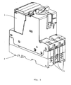
- Fig. 1
- eine perspektivische Ansicht eines zum erfindungsgemäßen Schaltgerätesystems gehörenden Leistungsschalters mit einem eingesteckten, baugleichen Auslösemodul;
- Fig. 2
- eine perspektivische Ansicht eines zum erfindungsgemäßen Schaltgerätesystems gehörenden Überlastrelais mit einem eingesteckten, baugleichen Auslösemodul;
- Fig. 3
- eine perspektivische Ansicht eines zum erfindungsgemäßen Schaltgerätesystems gehörendes, baugleiches Auslösemodul.
- Fig. 1
- a perspective view of belonging to the switching device system according to the invention circuit breaker with an inserted, identical trigger module;
- Fig. 2
- a perspective view of belonging to the switching device according to the invention overload relay with an inserted, identical trigger module;
- Fig. 3
- a perspective view of the switching device system according to the invention belonging, identical trigger module.
Die
Bekommt der Aktor ein Auslösesignal, wirkt er derart auf das Schaltschloss ein, dass das Schaltschloss die Hauptkontakte des Leistungsschalters 2 öffnet und somit die Hauptstrombahnen trennt. Das erste Auslösemodul umfasst Mittel zur Auswertung verschiedener Parameter der Hauptstrombahnen, wie beispielsweise Stromstärke, Über- oder Unterspannung sowie Temperaturen. Werden diese eingestellten Grenzwerte überschritten, steuert das erste Auslösemodul den im Leistungsschalter 2 befindlichen Aktor, welcher auf das Schaltschloss des Leistungsschalters 2 wirkt und die Hauptkontakte trennt.The
If the actuator receives a trigger signal, it acts on the switch lock in such a way that the switch lock opens the main contacts of the
Das Überlastrelais 3 umfasst ein Basisteil 34 sowie eingangsseitige und ausgangsseitige Anschlüsse 31. Einige der zweiten eingangs- und ausgangsseitigen Anschlüsse 31 sind in diesem Ausführungsbeispiel derart gestaltet, dass das Überlastrelais auf ein Schütz aufsteckbar ist und mit dem Schütz elektrisch und mechanisch verbunden ist. Das Überlastrelais 3 umfasst weiterhin ein zweites Auslösemodul, welches in das Basisteil 33 gesteckt ist. Werden eingestellte Grenzwerte überschritten, steuert das zweite Auslösemodul den im Überlastrelais 3 befindlichen Aktor an, welcher auf die Hilfskontakte 32 schließt und/oder über die ausgangsseitige Anschlüsse 31 das angeschlossene Schütz zum Trennen der Hauptkontakte öffnet.The
Das zweite Auslösemodul ist erfindungsgemäß elektrisch und mechanisch mit dem ersten Auslösemodul baugleich. Das bedeutet, dass zum einen die elektrischen Funktionen und Parameter des ersten und zweiten Auslösemoduls gleich sind (z.B. gleiche elektrische Bauteile und Verdrahtung). Zum anderen sind die Abmessungen und sonstige mechanischen Eigenschaften beider Auslösemodule gleich. Das baugleiche Auslösemodul 1 ist somit in den Leistungsschalter 2 sowie in das Überlastrelais 3 steckbar und weist Mittel zur Auswertung verschiedener Parameter, wie beispielsweise Stromstärke, Über- oder Unterspannung sowie Temperaturen auf den Hauptstrombahnen auf.The second tripping module according to the invention is electrically and mechanically identical to the first tripping module. This means that, on the one hand, the electrical functions and parameters of the first and second tripping module are the same (eg, the same electrical components and wiring). On the other hand, the dimensions and other mechanical properties of both release modules are the same. The
Das baugleiche Auslösemodul 1 umfasst Anschlusskontakte 11 zur Kontaktierung mit einem Leistungsschalter 2 oder einem Überlastrelais 3. Des Weiteren umfasst das baugleiche Auslösemodul 1 Auslösekontakte 13, welche ein Auslösesignal an den Leistungsschalter 2 oder das Überlastrelais 3 weiterleiten. Die dargestellte Ausführungsform umfasst weiterhin eine Kommunikationsverbindung 12, welche die Kommunikation eines Leistungsschalters 2 oder Überlastrelais 3 mit einem Bussystem ermöglicht. Über dieses Bussystem können Parameter des baugleichen Auslösemoduls 1 ausgelesen oder geändert werden, wenn das baugleiche Auslösemodul 1 entsprechende elektronische Einrichtungen umfasst.The
Das baugleiche Auslösemodul 1 kann Schmelzsicherungen umfassen, welche von außen ein- oder ausgeschraubt werden können. Eine Überwachungsschaltung gibt ein Auslösesignal über die Auslösekontakte an das Überlastrelais 3 oder den Leistungsschalter 2 weiter. Über die Kommunikationsverbindung 12 kann ebenfalls eine Zustandsmeldung weitergeben werden. Ausgelöste Schmelzsicherungen können einfach ausgewechselt werden. Alternativ kann das baugleiche Auslösemodul 1 Bimetallauslöser aufweisen, welche bei Erhöhung der Temperatur auf den Hauptstrombahnen ein Auslösesignal über die Auslösekontakte 13 an den Leistungsschalter 2 oder das Überlastrelais 3 weitergibt. Alternativ oder zusätzlich kann das baugleiche Auslösemodul 1 eine elektronische Überwachungsschaltung aufweisen, welche die Parameter überwacht und entsprechende Überschreitungen über die Auslösekontakte 13 oder die Kommunikationseinrichtung 12 weiterleitet.The structurally
Bezugszeichenliste:
- 1
- baugleiches Auslösemodul
- 11
- Anschlusskontakte
- 12
- Kommunikationsverbindung
- 13
- Auslösekontakte
- 2
- Leistungsschalter
- 21
- eingangs- und ausgangsseitige erste Anschlüsse
- 3
- Überlastrelais
- 31
- eingangs- und ausgangsseitige zweite Anschlüsse
- 32
- Hilfskontakte
- 33
- Basisteil
- 1
- identical release module
- 11
- terminals
- 12
- communication link
- 13
- trip contacts
- 2
- breakers
- 21
- input and output side first connections
- 3
- Overload relay
- 31
- input and output second connections
- 32
- auxiliary contacts
- 33
- base
Claims (4)
- Switching device system comprising:- a circuit breaker (2) comprising a detachable first trip module, a switching lock and first input and output-side connections (21), whereby the circuit breaker (2) is fitted with a first actuator which can be actuated by the first trip module for tripping the switching lock;- an overload relay (3) comprising a base part (33) with a second trip module connected with the base part and second input and output-side connections (31) and at least one auxiliary contact (32) whereby the base part (33) of the overload relay (3) is fitted with a second actuator which can be actuated by the second trip module for actuating at least one auxiliary contact (32) characterized in that- the first and the second trip modules are designed as electrically and mechanically equivalent trip modules (1),- the equivalent trip module (1) is detachably inserted, both in the circuit breaker (2) and in the overload relay (3),- the equivalent trip module (1) can be put in an operative connection both with the first actuator and with the second actuator.
- Switching device system according to Claim 1, characterized in that the equivalent trip module (1) comprises an electronic switch which sends a trip signal to the first or the second actuator in case of overload on at least one phase.
- Switching device system according to Claim 1, characterized in that the equivalent trip module (1) comprises at least one bimetal trip and sends a trip signal to the first or to the second actuator through an electronic evaluation device.
- Switching device system according to one of the Claims 1 to 3, characterized in that the equivalent trip module (1) comprises at least one fuse and the trip module sends a trip signal to the first actuator or to the second actuator with the help of a detection arrangement as soon as a fuse has tripped.
Applications Claiming Priority (1)
| Application Number | Priority Date | Filing Date | Title |
|---|---|---|---|
| DE200910008677 DE102009008677A1 (en) | 2009-02-12 | 2009-02-12 | Switchgear System |
Publications (2)
| Publication Number | Publication Date |
|---|---|
| EP2219199A1 EP2219199A1 (en) | 2010-08-18 |
| EP2219199B1 true EP2219199B1 (en) | 2015-03-25 |
Family
ID=42173543
Family Applications (1)
| Application Number | Title | Priority Date | Filing Date |
|---|---|---|---|
| EP20100001137 Not-in-force EP2219199B1 (en) | 2009-02-12 | 2010-02-04 | Switching device system |
Country Status (2)
| Country | Link |
|---|---|
| EP (1) | EP2219199B1 (en) |
| DE (1) | DE102009008677A1 (en) |
Families Citing this family (4)
| Publication number | Priority date | Publication date | Assignee | Title |
|---|---|---|---|---|
| EP2549515A1 (en) * | 2011-07-21 | 2013-01-23 | Eaton Industries GmbH | Switch assembly for producing and/or separating a connection between a male and a female connector |
| FR2985599B1 (en) * | 2012-01-09 | 2014-03-21 | Hager Electro Sas | ASSEMBLY OF A LINE PROTECTION ELECTRICAL APPARATUS INTO TWO BLOCKS. |
| DE102013008980B4 (en) * | 2012-07-28 | 2022-03-17 | Abb Schweiz Ag | remote control device |
| DE102012106963A1 (en) | 2012-07-31 | 2014-02-20 | Eaton Electrical Ip Gmbh & Co. Kg | Switchgear arrangement |
Family Cites Families (6)
| Publication number | Priority date | Publication date | Assignee | Title |
|---|---|---|---|---|
| FR2638563B1 (en) * | 1988-10-27 | 1990-12-14 | Telemecanique Electrique | SAFETY DEVICE FOR A SWITCHING APPARATUS MADE BY ASSEMBLING A PLURALITY OF REMOVABLE MODULAR ELEMENTS |
| DE4234619C2 (en) | 1992-10-14 | 1994-09-22 | Kloeckner Moeller Gmbh | Overload relay to be combined with contactors |
| FR2759489B1 (en) * | 1997-02-12 | 1999-03-19 | Schneider Electric Sa | COMPOSABLE MULTIPOLAR ELECTRICAL APPARATUS |
| FR2805094B1 (en) * | 2000-02-14 | 2002-03-29 | Schneider Electric Ind Sa | STARTER ASSEMBLY |
| FR2837617B1 (en) * | 2002-03-19 | 2004-05-28 | Schneider Electric Ind Sa | MULTIPOLAR ELECTRIC SWITCHING APPARATUS FOR CONTROLLING MOTORS |
| DE102006020702B4 (en) | 2006-05-04 | 2014-03-13 | Eaton Industries Gmbh | Circuit breaker for motor protection and / or line protection |
-
2009
- 2009-02-12 DE DE200910008677 patent/DE102009008677A1/en not_active Ceased
-
2010
- 2010-02-04 EP EP20100001137 patent/EP2219199B1/en not_active Not-in-force
Also Published As
| Publication number | Publication date |
|---|---|
| DE102009008677A1 (en) | 2010-08-19 |
| EP2219199A1 (en) | 2010-08-18 |
Similar Documents
| Publication | Publication Date | Title |
|---|---|---|
| DE602005000540T2 (en) | Over-voltage protection device | |
| WO2000079664A1 (en) | Electrical circuit breaker for protecting against overcurrents | |
| EP2219199B1 (en) | Switching device system | |
| DE19757026A1 (en) | Electrical fuse | |
| DE102015000576B4 (en) | Motor vehicle with switching device for an on-board power supply-operated component | |
| EP4377988A1 (en) | Circuit breaker | |
| DE102018210925B4 (en) | Electromechanical low-voltage protective switching device | |
| EP3726560A1 (en) | Compact protective switching device | |
| EP2064721B1 (en) | Switching device with integrated main current path tap | |
| EP0889569B1 (en) | Installation switchgear unit | |
| EP0343390A2 (en) | Motor starter with protection against short-circuit | |
| WO2004049535A1 (en) | Protective switch | |
| DE10148863A1 (en) | Overload protection for electrical equipment has irreversible circuit breaker in housing | |
| EP1735887B1 (en) | Fault-current circuit breaker | |
| EP4274041B1 (en) | Modular insulating material housing and multipole modular series installation device | |
| EP4367702A1 (en) | Circuit breaker | |
| DE102017221937A1 (en) | Arrangement for electrical monitoring of the switching state of a fuse | |
| DE102023204547A1 (en) | Modular multi-pole DIN rail mounted device | |
| WO2008131703A1 (en) | Module with automatic extension of a monitoring circuit | |
| DE102023201130A1 (en) | Compact DIN rail mounted device and multi-pole DIN rail mounted device | |
| DE202024102062U1 (en) | additional device for low-voltage electrical installations | |
| DE102023202388A1 (en) | Device module, DIN rail device and contact spring | |
| DE102016013561A1 (en) | battery system | |
| DE102021210821A1 (en) | protective switching device | |
| DE972703C (en) | Electric self-switch arrangement for feed damper |
Legal Events
| Date | Code | Title | Description |
|---|---|---|---|
| PUAI | Public reference made under article 153(3) epc to a published international application that has entered the european phase |
Free format text: ORIGINAL CODE: 0009012 |
|
| AK | Designated contracting states |
Kind code of ref document: A1 Designated state(s): AT BE BG CH CY CZ DE DK EE ES FI FR GB GR HR HU IE IS IT LI LT LU LV MC MK MT NL NO PL PT RO SE SI SK SM TR |
|
| AX | Request for extension of the european patent |
Extension state: AL BA RS |
|
| 17P | Request for examination filed |
Effective date: 20110215 |
|
| GRAP | Despatch of communication of intention to grant a patent |
Free format text: ORIGINAL CODE: EPIDOSNIGR1 |
|
| RIC1 | Information provided on ipc code assigned before grant |
Ipc: H01H 89/06 20060101ALI20140508BHEP Ipc: H01H 71/02 20060101AFI20140508BHEP |
|
| INTG | Intention to grant announced |
Effective date: 20140602 |
|
| GRAS | Grant fee paid |
Free format text: ORIGINAL CODE: EPIDOSNIGR3 |
|
| GRAA | (expected) grant |
Free format text: ORIGINAL CODE: 0009210 |
|
| AK | Designated contracting states |
Kind code of ref document: B1 Designated state(s): AT BE BG CH CY CZ DE DK EE ES FI FR GB GR HR HU IE IS IT LI LT LU LV MC MK MT NL NO PL PT RO SE SI SK SM TR |
|
| REG | Reference to a national code |
Ref country code: GB Ref legal event code: FG4D Free format text: NOT ENGLISH |
|
| REG | Reference to a national code |
Ref country code: CH Ref legal event code: EP |
|
| REG | Reference to a national code |
Ref country code: IE Ref legal event code: FG4D Free format text: LANGUAGE OF EP DOCUMENT: GERMAN |
|
| REG | Reference to a national code |
Ref country code: DE Ref legal event code: R096 Ref document number: 502010009185 Country of ref document: DE Effective date: 20150507 |
|
| REG | Reference to a national code |
Ref country code: AT Ref legal event code: REF Ref document number: 718296 Country of ref document: AT Kind code of ref document: T Effective date: 20150515 |
|
| RAP2 | Party data changed (patent owner data changed or rights of a patent transferred) |
Owner name: EATON ELECTRICAL IP GMBH & CO. KG |
|
| PG25 | Lapsed in a contracting state [announced via postgrant information from national office to epo] |
Ref country code: NO Free format text: LAPSE BECAUSE OF FAILURE TO SUBMIT A TRANSLATION OF THE DESCRIPTION OR TO PAY THE FEE WITHIN THE PRESCRIBED TIME-LIMIT Effective date: 20150625 Ref country code: SE Free format text: LAPSE BECAUSE OF FAILURE TO SUBMIT A TRANSLATION OF THE DESCRIPTION OR TO PAY THE FEE WITHIN THE PRESCRIBED TIME-LIMIT Effective date: 20150325 Ref country code: HR Free format text: LAPSE BECAUSE OF FAILURE TO SUBMIT A TRANSLATION OF THE DESCRIPTION OR TO PAY THE FEE WITHIN THE PRESCRIBED TIME-LIMIT Effective date: 20150325 Ref country code: FI Free format text: LAPSE BECAUSE OF FAILURE TO SUBMIT A TRANSLATION OF THE DESCRIPTION OR TO PAY THE FEE WITHIN THE PRESCRIBED TIME-LIMIT Effective date: 20150325 Ref country code: LT Free format text: LAPSE BECAUSE OF FAILURE TO SUBMIT A TRANSLATION OF THE DESCRIPTION OR TO PAY THE FEE WITHIN THE PRESCRIBED TIME-LIMIT Effective date: 20150325 |
|
| REG | Reference to a national code |
Ref country code: LT Ref legal event code: MG4D |
|
| PG25 | Lapsed in a contracting state [announced via postgrant information from national office to epo] |
Ref country code: LV Free format text: LAPSE BECAUSE OF FAILURE TO SUBMIT A TRANSLATION OF THE DESCRIPTION OR TO PAY THE FEE WITHIN THE PRESCRIBED TIME-LIMIT Effective date: 20150325 Ref country code: GR Free format text: LAPSE BECAUSE OF FAILURE TO SUBMIT A TRANSLATION OF THE DESCRIPTION OR TO PAY THE FEE WITHIN THE PRESCRIBED TIME-LIMIT Effective date: 20150626 |
|
| PG25 | Lapsed in a contracting state [announced via postgrant information from national office to epo] |
Ref country code: NL Free format text: LAPSE BECAUSE OF FAILURE TO SUBMIT A TRANSLATION OF THE DESCRIPTION OR TO PAY THE FEE WITHIN THE PRESCRIBED TIME-LIMIT Effective date: 20150325 |
|
| PG25 | Lapsed in a contracting state [announced via postgrant information from national office to epo] |
Ref country code: SK Free format text: LAPSE BECAUSE OF FAILURE TO SUBMIT A TRANSLATION OF THE DESCRIPTION OR TO PAY THE FEE WITHIN THE PRESCRIBED TIME-LIMIT Effective date: 20150325 Ref country code: EE Free format text: LAPSE BECAUSE OF FAILURE TO SUBMIT A TRANSLATION OF THE DESCRIPTION OR TO PAY THE FEE WITHIN THE PRESCRIBED TIME-LIMIT Effective date: 20150325 Ref country code: CZ Free format text: LAPSE BECAUSE OF FAILURE TO SUBMIT A TRANSLATION OF THE DESCRIPTION OR TO PAY THE FEE WITHIN THE PRESCRIBED TIME-LIMIT Effective date: 20150325 Ref country code: ES Free format text: LAPSE BECAUSE OF FAILURE TO SUBMIT A TRANSLATION OF THE DESCRIPTION OR TO PAY THE FEE WITHIN THE PRESCRIBED TIME-LIMIT Effective date: 20150325 Ref country code: RO Free format text: LAPSE BECAUSE OF FAILURE TO SUBMIT A TRANSLATION OF THE DESCRIPTION OR TO PAY THE FEE WITHIN THE PRESCRIBED TIME-LIMIT Effective date: 20150325 Ref country code: PT Free format text: LAPSE BECAUSE OF FAILURE TO SUBMIT A TRANSLATION OF THE DESCRIPTION OR TO PAY THE FEE WITHIN THE PRESCRIBED TIME-LIMIT Effective date: 20150727 |
|
| PG25 | Lapsed in a contracting state [announced via postgrant information from national office to epo] |
Ref country code: PL Free format text: LAPSE BECAUSE OF FAILURE TO SUBMIT A TRANSLATION OF THE DESCRIPTION OR TO PAY THE FEE WITHIN THE PRESCRIBED TIME-LIMIT Effective date: 20150325 Ref country code: IS Free format text: LAPSE BECAUSE OF FAILURE TO SUBMIT A TRANSLATION OF THE DESCRIPTION OR TO PAY THE FEE WITHIN THE PRESCRIBED TIME-LIMIT Effective date: 20150725 |
|
| REG | Reference to a national code |
Ref country code: DE Ref legal event code: R097 Ref document number: 502010009185 Country of ref document: DE |
|
| PG25 | Lapsed in a contracting state [announced via postgrant information from national office to epo] |
Ref country code: DK Free format text: LAPSE BECAUSE OF FAILURE TO SUBMIT A TRANSLATION OF THE DESCRIPTION OR TO PAY THE FEE WITHIN THE PRESCRIBED TIME-LIMIT Effective date: 20150325 |
|
| PLBE | No opposition filed within time limit |
Free format text: ORIGINAL CODE: 0009261 |
|
| STAA | Information on the status of an ep patent application or granted ep patent |
Free format text: STATUS: NO OPPOSITION FILED WITHIN TIME LIMIT |
|
| 26N | No opposition filed |
Effective date: 20160105 |
|
| PG25 | Lapsed in a contracting state [announced via postgrant information from national office to epo] |
Ref country code: IT Free format text: LAPSE BECAUSE OF FAILURE TO SUBMIT A TRANSLATION OF THE DESCRIPTION OR TO PAY THE FEE WITHIN THE PRESCRIBED TIME-LIMIT Effective date: 20150325 |
|
| PG25 | Lapsed in a contracting state [announced via postgrant information from national office to epo] |
Ref country code: BE Free format text: LAPSE BECAUSE OF NON-PAYMENT OF DUE FEES Effective date: 20160229 Ref country code: SI Free format text: LAPSE BECAUSE OF FAILURE TO SUBMIT A TRANSLATION OF THE DESCRIPTION OR TO PAY THE FEE WITHIN THE PRESCRIBED TIME-LIMIT Effective date: 20150325 |
|
| PG25 | Lapsed in a contracting state [announced via postgrant information from national office to epo] |
Ref country code: MC Free format text: LAPSE BECAUSE OF FAILURE TO SUBMIT A TRANSLATION OF THE DESCRIPTION OR TO PAY THE FEE WITHIN THE PRESCRIBED TIME-LIMIT Effective date: 20150325 Ref country code: LU Free format text: LAPSE BECAUSE OF FAILURE TO SUBMIT A TRANSLATION OF THE DESCRIPTION OR TO PAY THE FEE WITHIN THE PRESCRIBED TIME-LIMIT Effective date: 20160204 |
|
| REG | Reference to a national code |
Ref country code: CH Ref legal event code: PL |
|
| GBPC | Gb: european patent ceased through non-payment of renewal fee |
Effective date: 20160204 |
|
| PG25 | Lapsed in a contracting state [announced via postgrant information from national office to epo] |
Ref country code: LI Free format text: LAPSE BECAUSE OF NON-PAYMENT OF DUE FEES Effective date: 20160229 Ref country code: CH Free format text: LAPSE BECAUSE OF NON-PAYMENT OF DUE FEES Effective date: 20160229 |
|
| REG | Reference to a national code |
Ref country code: FR Ref legal event code: ST Effective date: 20161028 |
|
| REG | Reference to a national code |
Ref country code: IE Ref legal event code: MM4A |
|
| PG25 | Lapsed in a contracting state [announced via postgrant information from national office to epo] |
Ref country code: IE Free format text: LAPSE BECAUSE OF NON-PAYMENT OF DUE FEES Effective date: 20160204 Ref country code: FR Free format text: LAPSE BECAUSE OF NON-PAYMENT OF DUE FEES Effective date: 20160229 Ref country code: GB Free format text: LAPSE BECAUSE OF NON-PAYMENT OF DUE FEES Effective date: 20160204 |
|
| REG | Reference to a national code |
Ref country code: AT Ref legal event code: MM01 Ref document number: 718296 Country of ref document: AT Kind code of ref document: T Effective date: 20160204 |
|
| PGFP | Annual fee paid to national office [announced via postgrant information from national office to epo] |
Ref country code: DE Payment date: 20170227 Year of fee payment: 8 |
|
| PG25 | Lapsed in a contracting state [announced via postgrant information from national office to epo] |
Ref country code: AT Free format text: LAPSE BECAUSE OF NON-PAYMENT OF DUE FEES Effective date: 20160204 |
|
| PG25 | Lapsed in a contracting state [announced via postgrant information from national office to epo] |
Ref country code: MT Free format text: LAPSE BECAUSE OF FAILURE TO SUBMIT A TRANSLATION OF THE DESCRIPTION OR TO PAY THE FEE WITHIN THE PRESCRIBED TIME-LIMIT Effective date: 20150325 |
|
| PG25 | Lapsed in a contracting state [announced via postgrant information from national office to epo] |
Ref country code: CY Free format text: LAPSE BECAUSE OF FAILURE TO SUBMIT A TRANSLATION OF THE DESCRIPTION OR TO PAY THE FEE WITHIN THE PRESCRIBED TIME-LIMIT Effective date: 20150325 Ref country code: HU Free format text: LAPSE BECAUSE OF FAILURE TO SUBMIT A TRANSLATION OF THE DESCRIPTION OR TO PAY THE FEE WITHIN THE PRESCRIBED TIME-LIMIT; INVALID AB INITIO Effective date: 20100204 Ref country code: SM Free format text: LAPSE BECAUSE OF FAILURE TO SUBMIT A TRANSLATION OF THE DESCRIPTION OR TO PAY THE FEE WITHIN THE PRESCRIBED TIME-LIMIT Effective date: 20150325 |
|
| PG25 | Lapsed in a contracting state [announced via postgrant information from national office to epo] |
Ref country code: MK Free format text: LAPSE BECAUSE OF FAILURE TO SUBMIT A TRANSLATION OF THE DESCRIPTION OR TO PAY THE FEE WITHIN THE PRESCRIBED TIME-LIMIT Effective date: 20150325 Ref country code: TR Free format text: LAPSE BECAUSE OF FAILURE TO SUBMIT A TRANSLATION OF THE DESCRIPTION OR TO PAY THE FEE WITHIN THE PRESCRIBED TIME-LIMIT Effective date: 20150325 |
|
| PG25 | Lapsed in a contracting state [announced via postgrant information from national office to epo] |
Ref country code: BG Free format text: LAPSE BECAUSE OF FAILURE TO SUBMIT A TRANSLATION OF THE DESCRIPTION OR TO PAY THE FEE WITHIN THE PRESCRIBED TIME-LIMIT Effective date: 20150325 |
|
| REG | Reference to a national code |
Ref country code: DE Ref legal event code: R119 Ref document number: 502010009185 Country of ref document: DE |
|
| PG25 | Lapsed in a contracting state [announced via postgrant information from national office to epo] |
Ref country code: DE Free format text: LAPSE BECAUSE OF NON-PAYMENT OF DUE FEES Effective date: 20180901 |