EP0343390A2 - Motor starter with protection against short-circuit - Google Patents
Motor starter with protection against short-circuit Download PDFInfo
- Publication number
- EP0343390A2 EP0343390A2 EP89107513A EP89107513A EP0343390A2 EP 0343390 A2 EP0343390 A2 EP 0343390A2 EP 89107513 A EP89107513 A EP 89107513A EP 89107513 A EP89107513 A EP 89107513A EP 0343390 A2 EP0343390 A2 EP 0343390A2
- Authority
- EP
- European Patent Office
- Prior art keywords
- motor
- short
- protection
- circuit
- unit
- Prior art date
- Legal status (The legal status is an assumption and is not a legal conclusion. Google has not performed a legal analysis and makes no representation as to the accuracy of the status listed.)
- Granted
Links
Images
Classifications
-
- H—ELECTRICITY
- H01—ELECTRIC ELEMENTS
- H01H—ELECTRIC SWITCHES; RELAYS; SELECTORS; EMERGENCY PROTECTIVE DEVICES
- H01H71/00—Details of the protective switches or relays covered by groups H01H73/00 - H01H83/00
- H01H71/10—Operating or release mechanisms
- H01H71/1045—Multiple circuits-breaker, e.g. for the purpose of dividing current or potential drop
-
- H—ELECTRICITY
- H01—ELECTRIC ELEMENTS
- H01H—ELECTRIC SWITCHES; RELAYS; SELECTORS; EMERGENCY PROTECTIVE DEVICES
- H01H89/00—Combinations of two or more different basic types of electric switches, relays, selectors and emergency protective devices, not covered by any single one of the other main groups of this subclass
- H01H89/06—Combination of a manual reset circuit with a contactor, i.e. the same circuit controlled by both a protective and a remote control device
-
- H—ELECTRICITY
- H02—GENERATION; CONVERSION OR DISTRIBUTION OF ELECTRIC POWER
- H02H—EMERGENCY PROTECTIVE CIRCUIT ARRANGEMENTS
- H02H7/00—Emergency protective circuit arrangements specially adapted for specific types of electric machines or apparatus or for sectionalised protection of cable or line systems, and effecting automatic switching in the event of an undesired change from normal working conditions
- H02H7/22—Emergency protective circuit arrangements specially adapted for specific types of electric machines or apparatus or for sectionalised protection of cable or line systems, and effecting automatic switching in the event of an undesired change from normal working conditions for distribution gear, e.g. bus-bar systems; for switching devices
- H02H7/222—Emergency protective circuit arrangements specially adapted for specific types of electric machines or apparatus or for sectionalised protection of cable or line systems, and effecting automatic switching in the event of an undesired change from normal working conditions for distribution gear, e.g. bus-bar systems; for switching devices for switches
-
- H—ELECTRICITY
- H01—ELECTRIC ELEMENTS
- H01H—ELECTRIC SWITCHES; RELAYS; SELECTORS; EMERGENCY PROTECTIVE DEVICES
- H01H89/00—Combinations of two or more different basic types of electric switches, relays, selectors and emergency protective devices, not covered by any single one of the other main groups of this subclass
- H01H89/06—Combination of a manual reset circuit with a contactor, i.e. the same circuit controlled by both a protective and a remote control device
- H01H2089/065—Coordination between protection and remote control, e.g. protection job repartition, mutual assistance or monitoring
-
- H—ELECTRICITY
- H01—ELECTRIC ELEMENTS
- H01H—ELECTRIC SWITCHES; RELAYS; SELECTORS; EMERGENCY PROTECTIVE DEVICES
- H01H71/00—Details of the protective switches or relays covered by groups H01H73/00 - H01H83/00
- H01H71/10—Operating or release mechanisms
- H01H71/12—Automatic release mechanisms with or without manual release
- H01H71/123—Automatic release mechanisms with or without manual release using a solid-state trip unit
-
- H—ELECTRICITY
- H02—GENERATION; CONVERSION OR DISTRIBUTION OF ELECTRIC POWER
- H02H—EMERGENCY PROTECTIVE CIRCUIT ARRANGEMENTS
- H02H3/00—Emergency protective circuit arrangements for automatic disconnection directly responsive to an undesired change from normal electric working condition with or without subsequent reconnection ; integrated protection
- H02H3/08—Emergency protective circuit arrangements for automatic disconnection directly responsive to an undesired change from normal electric working condition with or without subsequent reconnection ; integrated protection responsive to excess current
- H02H3/093—Emergency protective circuit arrangements for automatic disconnection directly responsive to an undesired change from normal electric working condition with or without subsequent reconnection ; integrated protection responsive to excess current with timing means
- H02H3/0935—Emergency protective circuit arrangements for automatic disconnection directly responsive to an undesired change from normal electric working condition with or without subsequent reconnection ; integrated protection responsive to excess current with timing means the timing being determined by numerical means
-
- H—ELECTRICITY
- H02—GENERATION; CONVERSION OR DISTRIBUTION OF ELECTRIC POWER
- H02H—EMERGENCY PROTECTIVE CIRCUIT ARRANGEMENTS
- H02H7/00—Emergency protective circuit arrangements specially adapted for specific types of electric machines or apparatus or for sectionalised protection of cable or line systems, and effecting automatic switching in the event of an undesired change from normal working conditions
- H02H7/08—Emergency protective circuit arrangements specially adapted for specific types of electric machines or apparatus or for sectionalised protection of cable or line systems, and effecting automatic switching in the event of an undesired change from normal working conditions for dynamo-electric motors
- H02H7/0816—Emergency protective circuit arrangements specially adapted for specific types of electric machines or apparatus or for sectionalised protection of cable or line systems, and effecting automatic switching in the event of an undesired change from normal working conditions for dynamo-electric motors concerning the starting sequence, e.g. limiting the number of starts per time unit, monitoring speed during starting
Definitions
- the invention relates to a motor starter for starting and stopping electric motors according to the preamble of claim 1.
- a contactor which has short-circuit protection properties as a single device. So in the event of a short circuit A reliable lifting of the movable contact bridge is achieved, this contactor, a magnetic compensator, which counteracts the electrodynamic repulsive forces occurring in the contact system, must be equipped with a release device that enables a quick and clear opening of the contacts at a certain current threshold. In addition, damping means must be provided to prevent the contact bridge from falling back prematurely within the 1st half-wave of the short-circuit current.
- the invention has for its object to provide inexpensive and user-friendly "self-coordinating" combined starters.
- the invention has the advantage that the combined starter is constructed from the same switching devices and thus the use of fewer different parts is possible.
- a coordination of different devices to form a device system, as is required in the previously known combined starters, is dispensed with since the starter according to the invention can be constructed as a complete switching device.
- the control and monitoring of the contactors with intelligent power electronics (“Smart Power Device”) replaces the conventional releases such as bimetallic relays and quick releases and bypasses the complex constructions that enable short-circuit current release.
- Smart Power Device replaces the conventional releases such as bimetallic relays and quick releases and bypasses the complex constructions that enable short-circuit current release.
- Another advantage of electronic overload monitoring is the large setting and application areas of these triggers.
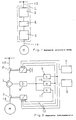
- the motor starter 1 shown in FIG. 1 consists of a line-side contactor 2 and a load-side contactor 3 connected to it in series.
- the electronic measuring, control and monitoring unit 4 is inserted between the two contactors.
- the network and load side connection is made via connections 13 and 14.
- Fig. 2 shows that the electronic measuring, control and monitoring device 4, which consists of the measured value acquisition 7, the measured value processing 8, and the electronic b-, s- and k-releases 9, 10 and 11, the control lines 12 act on contactors 2 and 3.
- the ON / OFF function of the starter is carried out via the actuation unit 5, which acts on contactor 2.
- the operating control of the motor is carried out with the actuating unit 6 in conjunction with contactor 3.
- the s- and k-releases 9 and 10 act on both contactors 2, 3.
- the contact separation is initiated simultaneously on both contactors 2, 3.
- the contactors 2, 3 must have approximately the same lifting currents, which are determined by features of the structural design of the individual contactors 2, 3.
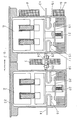
- Fig. 3 shows that the fixed contact carrier 15, 16, 17, 18 have the shape of a U. This enables the electrodynamic repulsion of the movable contact bridges 19, 20 against the force of the pole springs 21, 22 when a strong current, such as a short-circuit overcurrent, flows in the starter circuit.
- the contactors 2 and 3 are arranged one above the other on a base plate 23. The contactors are connected in series by means of a mechanical, electrically conductive connection 24 of the connections 25, 26 of the fixed contact carriers 17, 18. The connection 24 takes place simultaneously the transducer 7 of the unit 4.
- the electronic measuring, control and monitoring unit (4) can be designed as a "Smart Power Device" in any manner at a suitable location on an outer wall of the motor starter. This also applies to the actuating elements 5, 6.
- FIG. 3 shows an attachment of these components to the load side of the motor starter (seen from the front).
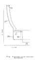
- the tripping characteristics of the electronic triggers 9, 10 and 11 are shown.
- the options for varying the setting values for electronic triggers are shown.
- the characteristic curves of the b-, s- and k-triggers are designated in sequence with 27, 28 and 29.
- the setting range of the b-release is labeled 30. With the s-release, the current setting range 31 and the time delay 32 can be varied.
- the invention can be used with appropriately adapted contactors in single and multi-phase starter circuits.
Abstract
Description
Die Erfindung betrifft einen Motorstarter zum Ingang- und Stillsetzen von Elektromotoren gemäß dem Oberbegriff des Anspruchs 1.The invention relates to a motor starter for starting and stopping electric motors according to the preamble of
Motorstarter mit Kurzschlußschutz sind als "kombinierte Starter" bekannt. Bei diesen Startern wird einem Schütz, mit dem der Motor im Normalbetrieb gesteuert wird, ein Leistungsschalter vorgeschaltet, der beim Auftreten von Kurzschlußströmen schnell genug den Strompfad trennt und so den zu steuernden Verbraucher und die anderen Schaltgeräte des Starters schützt. Die dabei zu leistende Lichtbogenarbeit der Kurzschlußstromtrennung wird allein von dem Leistungsschalter der Starterkombination geleistet. Die bekannten kombinierten Starter weisen einen engen Einsatzbereich auf, müssen mit einzelnen Schaltgeräten vom Anwender koordiniert und aufgebaut werden und bestehen aus mehreren unterschiedlichen Schaltgerätetypen und zusätzlichen Hilfsgeräten wie Sicherungen oder Überstromrelais. Mögliche Ausführungen derartiger Starter sind in einem Entwurf der DIN/VDE 0660 Teil 102 dargestellt.Motor starters with short-circuit protection are known as "combined starters". With these starters, a contactor with which the motor is controlled in normal operation is preceded by a circuit breaker which disconnects the current path quickly enough in the event of short-circuit currents and thus protects the load to be controlled and the starter's other switching devices. The arc work of the short-circuit current separation to be performed is performed solely by the circuit breaker of the starter combination. The known combined starters have a narrow field of application, have to be coordinated and set up by the user with individual switching devices and consist of several different switching device types and additional auxiliary devices such as fuses or overcurrent relays. Possible designs of such starters are shown in a draft of DIN / VDE 0660 part 102.
Weiterhin ist z.Bsp. aus der DE 35 03 431 A1 ein Schütz bekannt, das als Einzelgerät Kurzschlußschutzeigenschaften besitzt. Damit im Kurzschlußfall ein sicheres Abheben der beweglichen Kontaktbrücke errreicht wird, muß bei diesem Schütz ein magnetischer Ausgleicher, der den in dem Kontaktsystem auftretenden elektrodynamischen Abstoßungskräften entgegenwirkt, mit einer Freigabevorrichtung ausgerüstet sein, die bei einer bestimmten Stromschwelle ein schnelles und eindeutiges Öffnen der Kontakte ermöglicht. Zusätzlich müssen noch Dämpfungsmittel vorgesehen sein, die ein vorzeitiges Rückfallen der Kontaktbrücke innerhalb der 1. Halbwelle des Kurzschlußstromes verhindern.Furthermore, e.g. from DE 35 03 431 A1 a contactor is known which has short-circuit protection properties as a single device. So in the event of a short circuit A reliable lifting of the movable contact bridge is achieved, this contactor, a magnetic compensator, which counteracts the electrodynamic repulsive forces occurring in the contact system, must be equipped with a release device that enables a quick and clear opening of the contacts at a certain current threshold. In addition, damping means must be provided to prevent the contact bridge from falling back prematurely within the 1st half-wave of the short-circuit current.
Reihenschaltungen von Trennstellen, bei denen im Kurzschlußfall die zu leistende Lichtbogenarbeit auf mehrere Trennstellen verteilt wird, sind z. Bsp. aus der DE-AS 11 92 731 bekannt. Dort wird ein Selbstschalter gezeigt, dem ein Kontaktsystem vorgeschaltet ist, das die gleichen Trenneigenschaften wie das Kontaktsystem des Selbstschalters besitzt, und als Bauteil, bestehend aus Kontakttrennstelle, Auslöseeinheit und Eingangsklemmen, dem Selbstschalter beigeordnet werden kann. Dabei sind zwischen dem Selbstschalter und dem Bauteil nur elektrische Verbindungen erforderlich.Series connections of separation points, in which in the event of a short circuit the arc work to be performed is distributed over several separation points, z. For example, known from DE-AS 11 92 731. There, a self-switch is shown, which is preceded by a contact system that has the same disconnection properties as the contact system of the self-switch, and can be assigned to the self-switch as a component consisting of contact disconnection point, trip unit and input terminals. Only electrical connections are required between the auto switch and the component.
Der Erfindung liegt die Aufgabe zugrunde, kostengünstige und anwenderfreundliche "selbstkoordinierende" kombinierte Starter zu schaffen.The invention has for its object to provide inexpensive and user-friendly "self-coordinating" combined starters.
Diese Aufgabe wird durch die im Kennzeichen des Anspruchs 1 angegebenen Merkmale gelöst. Weiterbildungen sind in den Unteransprüchen gegeben.This object is achieved by the features specified in the characterizing part of
Die Erfindung hat den Vorteil, daß der kombinierte Starter aus gleichartigen Schaltgeräten aufgebaut ist und somit die Verwendung weniger verschiedener Teile möglich ist. Eine Koordination verschiedener Geräte zu einem Gerätesystem, wie es bei den bisher bekannten kombinierten Startern erforderlich ist, entfällt, da der erfindungsgemäße Starter als ein komplettes Schaltgerät aufgebaut werden kann. Die Steuerung und Überwachung der Schütze mit einer intelligenten leistungselektronik ("Smart Power Device") ersetzt die herkömmlichen Auslöser wie Bimetallrelais und Schnellauslöser und umgeht die aufwendigen Konstruktionen, die eine Kurzschlußstromauslösung ermöglichen. Ein weiterer Vorteil der elektronischen Überlastüberwachung ist durch die großen Einstell- und Einsatzbereiche dieser Auslöser gegeben.The invention has the advantage that the combined starter is constructed from the same switching devices and thus the use of fewer different parts is possible. A coordination of different devices to form a device system, as is required in the previously known combined starters, is dispensed with since the starter according to the invention can be constructed as a complete switching device. The control and monitoring of the contactors with intelligent power electronics ("Smart Power Device") replaces the conventional releases such as bimetallic relays and quick releases and bypasses the complex constructions that enable short-circuit current release. Another advantage of electronic overload monitoring is the large setting and application areas of these triggers.
Anhand des in der Zeichnung dargestellten Ausführungsbeispieles soll die Erfindung näher erläutert werden.
- Fig. 1 zeigt als Blockschaltbild den schematischen Aufbau des Motorstarters und seine Anbindung an Verbraucher und Netz.
- Fig. 2 zeigt ein Funktionsschaltbild des Motorsstartes.
- Fig. 3 zeigt den Motorstarter in geschnittener Draufsicht.
- Fig. 4 zeigt die Auslösekennlinien der elektronischen Überstromauslöser.
- Fig. 1 shows a block diagram of the schematic structure of the motor starter and its connection to consumers and the network.
- Fig. 2 shows a functional circuit diagram of the engine start.
- Fig. 3 shows the motor starter in a sectional plan view.
- Fig. 4 shows the tripping characteristics of the electronic overcurrent release.
Der in Fig. 1 dargestellte Motorstarter 1 besteht aus aus einem netzseitigen Schütz 2 und einem dazu in Reihe geschalteten lastseitigen Schütz 3. Zwischen den beiden Schützen ist die elektronische Meß-, Steuer- und Überwachungseinheit 4 eingefügt. Der netz- und lastseitige Anschluß erfolgt über die Anschlüsse 13 und 14.The
Fig. 2 zeigt, daß die elektronische Meß-, Steuer- und Überwachungseinrichtung 4 , die aus der Meßwerterfassung 7, der Meßwertaufbereitung 8, sowie aus den elektronischen b-, s- und k-Auslösern 9, 10 und 11 besteht, die über Steuerleitungen 12 auf die Schütze 2 und 3 einwirken. Die EIN-/Aus-Funktion des Starters wird über die Betätigungseinheit 5 ausgeführt, die auf Schütz 2 wirkt. Mit der Betätigungseinheit 6 wird in Verbindung mit Schütz 3 die Betriebssteuerung des Motors ausgeführt. Der b-Auslöser 11, der auf eine thermische Überlastung des Motors reagiert, wirkt nur auf Schütz 3. Die s- und k-Auslöser 9 und 10 wirken auf beide Schütze 2,3. So wird bei einer Überlastung, die zu einer Schnell- oder Kurzschlußstromauslösung führt, an beiden Schützen 2, 3 gleichzeitig die Kontakttrennung eingeleitet. Dazu müssen die Schütze 2, 3 annähern gleiche Abhebeströme ausweisen, die durch Merkmale der baulichen Ausführung der einzelnen Schütze 2, 3 bestimmt sind.Fig. 2 shows that the electronic measuring, control and
Fig. 3 zeigt, daß die feststehenden Kontaktträger 15, 16, 17, 18 die Form eines U besitzen. Dadurch wird die elektrodynamische Abstoßung der beweglichen Kontaktbrücken 19, 20 gegen die Kraft der Polfedern 21, 22 ermöglicht, wenn ein starker Strom, wie eine Kurzschlußüberstromstärke in dem Starterkreis fließt. Die Schütze 2 und 3 sind übereinander auf einer Grundplatte 23 angeordnet. Die Reihenschaltung der Schütze erfolgt durch eine mechanische, elektrisch leitende Verbindung 24 der Anschlüsse 25, 26 der festen Kontaktträger 17, 18. Die Verbindung 24 nimmt gleichzeitig den Meßwertaufnehmer 7 der Einheit 4 auf. Die elektronische Meß-, Steuer- und Überwachungseinheit (4) kann als "Smart Power Device" ausgeführt in beliebiger Weise an einer geeigneten Stelle einer Außenwand des Motorstarters befestigt sein. Das gilt auch für die Betätigungselemente 5, 6. Fig. 3 zeigt eine Befestigung dieser Bauteile an der Lastseite des Motorstarters (von vorne gesehen).Fig. 3 shows that the
In Fig. 4 sind die Auslösekennlinien der elektronischen Auslöser 9, 10 und 11 gezeigt. Dabei sind die für elektronische Auslöser gegebenen Möglichkeiten der Variation der Einstellwerte aufgezeigt. Die Kennlinien der b-, s- und k-Auslöser sind der Reihenfolge nach mit 27, 28 und 29 bezeichnet. Der Einstellbereich des b-Auslösers ist mit 30 bezeichnet. Beim s-Auslöser kann der Strom-Einstellbereich 31 und die Zeitverzögerung 32 variiert werden.4, the tripping characteristics of the
Die Erfindung ist mit entsprechend angepaßten Schützen in ein- und mehrphasigen Starterkreisen einsetzbar.The invention can be used with appropriately adapted contactors in single and multi-phase starter circuits.
Claims (4)
Applications Claiming Priority (2)
| Application Number | Priority Date | Filing Date | Title |
|---|---|---|---|
| DE3817528 | 1988-05-24 | ||
| DE3817528A DE3817528A1 (en) | 1988-05-24 | 1988-05-24 | MOTOR STARTER WITH SHORT CIRCUIT PROTECTION |
Publications (3)
| Publication Number | Publication Date |
|---|---|
| EP0343390A2 true EP0343390A2 (en) | 1989-11-29 |
| EP0343390A3 EP0343390A3 (en) | 1991-07-24 |
| EP0343390B1 EP0343390B1 (en) | 1995-08-23 |
Family
ID=6354973
Family Applications (1)
| Application Number | Title | Priority Date | Filing Date |
|---|---|---|---|
| EP89107513A Expired - Lifetime EP0343390B1 (en) | 1988-05-24 | 1989-04-26 | Motor starter with protection against short-circuit |
Country Status (3)
| Country | Link |
|---|---|
| EP (1) | EP0343390B1 (en) |
| DE (2) | DE3817528A1 (en) |
| ES (1) | ES2076169T3 (en) |
Cited By (6)
| Publication number | Priority date | Publication date | Assignee | Title |
|---|---|---|---|---|
| EP0757369A2 (en) * | 1995-08-04 | 1997-02-05 | Schneider Electric Sa | Four pole contactor |
| WO2001088939A1 (en) * | 2000-05-16 | 2001-11-22 | Siemens Aktiengesellschaft | Consumer junction |
| WO2002086929A1 (en) * | 2001-04-20 | 2002-10-31 | Siemens Aktiengesellschaft | Switchgear unit for a consumer, especially a motor starter |
| CN103117195A (en) * | 2012-08-29 | 2013-05-22 | 胡颖楠 | Sulfur hexafluoride breaker intelligent opening-and-closing brake operation mechanism |
| EP1994621B1 (en) * | 2006-03-14 | 2014-08-20 | Eaton Electrical IP GmbH & Co. KG | Electronic tripping unit for a motor-circuit breaker of an electric motor |
| DE102017223250A1 (en) | 2017-12-19 | 2019-06-19 | Siemens Aktiengesellschaft | Motor starter, operating method, computer program product and motor starter arrangement |
Families Citing this family (1)
| Publication number | Priority date | Publication date | Assignee | Title |
|---|---|---|---|---|
| DE4335965A1 (en) * | 1993-10-21 | 1995-04-27 | Licentia Gmbh | Motor starter (engine starter) having integrated short-circuit protection |
Citations (3)
| Publication number | Priority date | Publication date | Assignee | Title |
|---|---|---|---|---|
| DE1192731B (en) * | 1962-03-27 | 1965-05-13 | Licentia Gmbh | Circuit breaker with several separating points in series |
| US3717792A (en) * | 1971-07-23 | 1973-02-20 | Ite Imperial Corp | Leakage current interrupter device |
| DE3432476A1 (en) * | 1984-09-04 | 1986-03-13 | Siemens AG, 1000 Berlin und 8000 München | Switching contactor |
Family Cites Families (1)
| Publication number | Priority date | Publication date | Assignee | Title |
|---|---|---|---|---|
| FR2559308B1 (en) * | 1984-02-03 | 1986-10-17 | Telemecanique Electrique | CONTACT EQUIPPED WITH A MAGNETIC COMPENSATOR WITH ADJUSTABLE RELEASE THRESHOLD AND CIRCUIT-BREAKER USING SUCH A CONTACT |
-
1988
- 1988-05-24 DE DE3817528A patent/DE3817528A1/en active Granted
-
1989
- 1989-04-26 EP EP89107513A patent/EP0343390B1/en not_active Expired - Lifetime
- 1989-04-26 ES ES89107513T patent/ES2076169T3/en not_active Expired - Lifetime
- 1989-04-26 DE DE58909392T patent/DE58909392D1/en not_active Expired - Fee Related
Patent Citations (3)
| Publication number | Priority date | Publication date | Assignee | Title |
|---|---|---|---|---|
| DE1192731B (en) * | 1962-03-27 | 1965-05-13 | Licentia Gmbh | Circuit breaker with several separating points in series |
| US3717792A (en) * | 1971-07-23 | 1973-02-20 | Ite Imperial Corp | Leakage current interrupter device |
| DE3432476A1 (en) * | 1984-09-04 | 1986-03-13 | Siemens AG, 1000 Berlin und 8000 München | Switching contactor |
Cited By (11)
| Publication number | Priority date | Publication date | Assignee | Title |
|---|---|---|---|---|
| EP0757369A2 (en) * | 1995-08-04 | 1997-02-05 | Schneider Electric Sa | Four pole contactor |
| FR2737602A1 (en) * | 1995-08-04 | 1997-02-07 | Schneider Electric Sa | TETRAPOLAR CONTACTOR |
| EP0757369A3 (en) * | 1995-08-04 | 1997-03-12 | Schneider Electric Sa | Four pole contactor |
| WO2001088939A1 (en) * | 2000-05-16 | 2001-11-22 | Siemens Aktiengesellschaft | Consumer junction |
| WO2002086929A1 (en) * | 2001-04-20 | 2002-10-31 | Siemens Aktiengesellschaft | Switchgear unit for a consumer, especially a motor starter |
| US7012800B2 (en) | 2001-04-20 | 2006-03-14 | Siemens Aktiengesellschaft | Switchgear unit for a consumer, especially a motor starter |
| EP1994621B1 (en) * | 2006-03-14 | 2014-08-20 | Eaton Electrical IP GmbH & Co. KG | Electronic tripping unit for a motor-circuit breaker of an electric motor |
| CN103117195A (en) * | 2012-08-29 | 2013-05-22 | 胡颖楠 | Sulfur hexafluoride breaker intelligent opening-and-closing brake operation mechanism |
| DE102017223250A1 (en) | 2017-12-19 | 2019-06-19 | Siemens Aktiengesellschaft | Motor starter, operating method, computer program product and motor starter arrangement |
| US10594231B2 (en) | 2017-12-19 | 2020-03-17 | Siemens Aktiengesellschaft | Motor starter, operating method, computer program product and motor starter arrangement |
| EP3979283A1 (en) | 2017-12-19 | 2022-04-06 | Siemens Aktiengesellschaft | Motor starter, operating method, computer program product and motor starter assembly |
Also Published As
| Publication number | Publication date |
|---|---|
| DE3817528A1 (en) | 1989-12-07 |
| DE58909392D1 (en) | 1995-09-28 |
| DE3817528C2 (en) | 1992-01-16 |
| ES2076169T3 (en) | 1995-11-01 |
| EP0343390A3 (en) | 1991-07-24 |
| EP0343390B1 (en) | 1995-08-23 |
Similar Documents
| Publication | Publication Date | Title |
|---|---|---|
| EP1186084B1 (en) | Electrical circuit breaker for protecting against overcurrents | |
| EP2048679A1 (en) | Circuit breaker assembly | |
| DE670790C (en) | Thermal self-switch | |
| DE4335965A1 (en) | Motor starter (engine starter) having integrated short-circuit protection | |
| DE60213329T2 (en) | Power switch with cast housing with connection terminal | |
| EP0343390B1 (en) | Motor starter with protection against short-circuit | |
| EP1685578B1 (en) | Circuit breaker comprising a fuse | |
| EP0483591A2 (en) | Low tension switch device | |
| EP0350825A2 (en) | Electrical switch gear | |
| DE4110335A1 (en) | LV circuit short circuit branch - protects components against overcurrent by closing bridging branch to by=pass them when short circuit exists | |
| EP1101234B1 (en) | Device for short-circuit protection | |
| EP0453776B1 (en) | Switchgear with a circuit breaker or a load break switch and a fuse | |
| EP0691046B1 (en) | Arrangement for disconnecting branches of a low voltage supply network under short circuit conditions | |
| EP0827251B1 (en) | Electrical low voltage switchgear | |
| DE60027255T2 (en) | Circuit-breaker with cast housing and additional device | |
| DE3133200A1 (en) | Line protection circuit breaker, suitable for use as a preliminary automatic circuit breaker | |
| DE2702181C3 (en) | Short-circuit protection circuit for devices that can be switched on or off via semiconductor switches, in particular for light control devices | |
| DE69734277T2 (en) | NULL OPEN CIRCUIT | |
| EP0889569A2 (en) | Installation apparatus | |
| DE488671C (en) | Automatic switch for circuits whose current strength during the switch-on period is greater than after it has been switched on | |
| DE2610951A1 (en) | CIRCUIT BREAKER | |
| DE2536441C3 (en) | Current-limiting circuit breaker with series connection measures to increase the switching capacity | |
| DE1192731B (en) | Circuit breaker with several separating points in series | |
| EP0504464B1 (en) | Switching device for interrupting a circuit | |
| EP4080539A1 (en) | Protective switch with overload protection |
Legal Events
| Date | Code | Title | Description |
|---|---|---|---|
| PUAI | Public reference made under article 153(3) epc to a published international application that has entered the european phase |
Free format text: ORIGINAL CODE: 0009012 |
|
| AK | Designated contracting states |
Kind code of ref document: A2 Designated state(s): DE ES FR GB IT SE |
|
| PUAL | Search report despatched |
Free format text: ORIGINAL CODE: 0009013 |
|
| AK | Designated contracting states |
Kind code of ref document: A3 Designated state(s): DE ES FR GB IT SE |
|
| 17P | Request for examination filed |
Effective date: 19920115 |
|
| 17Q | First examination report despatched |
Effective date: 19940503 |
|
| GRAA | (expected) grant |
Free format text: ORIGINAL CODE: 0009210 |
|
| AK | Designated contracting states |
Kind code of ref document: B1 Designated state(s): DE ES FR GB IT SE |
|
| GBT | Gb: translation of ep patent filed (gb section 77(6)(a)/1977) |
Effective date: 19950829 |
|
| REF | Corresponds to: |
Ref document number: 58909392 Country of ref document: DE Date of ref document: 19950928 |
|
| REG | Reference to a national code |
Ref country code: ES Ref legal event code: FG2A Ref document number: 2076169 Country of ref document: ES Kind code of ref document: T3 |
|
| ITF | It: translation for a ep patent filed |
Owner name: MODIANO & ASSOCIATI S.R.L. |
|
| ET | Fr: translation filed | ||
| PGFP | Annual fee paid to national office [announced via postgrant information from national office to epo] |
Ref country code: GB Payment date: 19960325 Year of fee payment: 8 |
|
| PGFP | Annual fee paid to national office [announced via postgrant information from national office to epo] |
Ref country code: FR Payment date: 19960402 Year of fee payment: 8 |
|
| PGFP | Annual fee paid to national office [announced via postgrant information from national office to epo] |
Ref country code: SE Payment date: 19960404 Year of fee payment: 8 |
|
| PGFP | Annual fee paid to national office [announced via postgrant information from national office to epo] |
Ref country code: ES Payment date: 19960416 Year of fee payment: 8 |
|
| PLBE | No opposition filed within time limit |
Free format text: ORIGINAL CODE: 0009261 |
|
| STAA | Information on the status of an ep patent application or granted ep patent |
Free format text: STATUS: NO OPPOSITION FILED WITHIN TIME LIMIT |
|
| 26N | No opposition filed | ||
| PG25 | Lapsed in a contracting state [announced via postgrant information from national office to epo] |
Ref country code: DE Effective date: 19970101 |
|
| PG25 | Lapsed in a contracting state [announced via postgrant information from national office to epo] |
Ref country code: GB Effective date: 19970426 |
|
| PG25 | Lapsed in a contracting state [announced via postgrant information from national office to epo] |
Ref country code: SE Effective date: 19970427 |
|
| PG25 | Lapsed in a contracting state [announced via postgrant information from national office to epo] |
Ref country code: ES Free format text: LAPSE BECAUSE OF NON-PAYMENT OF DUE FEES Effective date: 19970428 |
|
| GBPC | Gb: european patent ceased through non-payment of renewal fee |
Effective date: 19970426 |
|
| PG25 | Lapsed in a contracting state [announced via postgrant information from national office to epo] |
Ref country code: FR Free format text: LAPSE BECAUSE OF NON-PAYMENT OF DUE FEES Effective date: 19971231 |
|
| EUG | Se: european patent has lapsed |
Ref document number: 89107513.7 |
|
| REG | Reference to a national code |
Ref country code: FR Ref legal event code: ST |
|
| REG | Reference to a national code |
Ref country code: ES Ref legal event code: FD2A Effective date: 19990405 |
|
| PG25 | Lapsed in a contracting state [announced via postgrant information from national office to epo] |
Ref country code: IT Free format text: LAPSE BECAUSE OF NON-PAYMENT OF DUE FEES;WARNING: LAPSES OF ITALIAN PATENTS WITH EFFECTIVE DATE BEFORE 2007 MAY HAVE OCCURRED AT ANY TIME BEFORE 2007. THE CORRECT EFFECTIVE DATE MAY BE DIFFERENT FROM THE ONE RECORDED. Effective date: 20050426 |