EP2218906A1 - Fuel injector - Google Patents
Fuel injector Download PDFInfo
- Publication number
- EP2218906A1 EP2218906A1 EP09180310A EP09180310A EP2218906A1 EP 2218906 A1 EP2218906 A1 EP 2218906A1 EP 09180310 A EP09180310 A EP 09180310A EP 09180310 A EP09180310 A EP 09180310A EP 2218906 A1 EP2218906 A1 EP 2218906A1
- Authority
- EP
- European Patent Office
- Prior art keywords
- sleeve
- coupler
- fuel injector
- spring element
- valve piston
- Prior art date
- Legal status (The legal status is an assumption and is not a legal conclusion. Google has not performed a legal analysis and makes no representation as to the accuracy of the status listed.)
- Granted
Links
Images


Classifications
-
- F—MECHANICAL ENGINEERING; LIGHTING; HEATING; WEAPONS; BLASTING
- F02—COMBUSTION ENGINES; HOT-GAS OR COMBUSTION-PRODUCT ENGINE PLANTS
- F02M—SUPPLYING COMBUSTION ENGINES IN GENERAL WITH COMBUSTIBLE MIXTURES OR CONSTITUENTS THEREOF
- F02M63/00—Other fuel-injection apparatus having pertinent characteristics not provided for in groups F02M39/00 - F02M57/00 or F02M67/00; Details, component parts, or accessories of fuel-injection apparatus, not provided for in, or of interest apart from, the apparatus of groups F02M39/00 - F02M61/00 or F02M67/00; Combination of fuel pump with other devices, e.g. lubricating oil pump
- F02M63/0012—Valves
- F02M63/0014—Valves characterised by the valve actuating means
- F02M63/0015—Valves characterised by the valve actuating means electrical, e.g. using solenoid
- F02M63/0026—Valves characterised by the valve actuating means electrical, e.g. using solenoid using piezoelectric or magnetostrictive actuators
-
- F—MECHANICAL ENGINEERING; LIGHTING; HEATING; WEAPONS; BLASTING
- F02—COMBUSTION ENGINES; HOT-GAS OR COMBUSTION-PRODUCT ENGINE PLANTS
- F02M—SUPPLYING COMBUSTION ENGINES IN GENERAL WITH COMBUSTIBLE MIXTURES OR CONSTITUENTS THEREOF
- F02M2200/00—Details of fuel-injection apparatus, not otherwise provided for
- F02M2200/70—Linkage between actuator and actuated element, e.g. between piezoelectric actuator and needle valve or pump plunger
- F02M2200/703—Linkage between actuator and actuated element, e.g. between piezoelectric actuator and needle valve or pump plunger hydraulic
Definitions
- the invention relates to a fuel injector for injecting fuel into a combustion chamber of an internal combustion engine according to the preamble of claim 1.
- Such fuel injectors are known from the prior art.
- the publication DE 10 2006 042 601 A1 discloses an injector for injecting fuel into a combustion chamber of an internal combustion engine, in which an injection valve member for releasing or closing at least one injection port is driven by an actuator-operated control valve.
- a hydraulic coupler unit is arranged, which in the example known from the prior art comprises a first piston operatively connected to the actuator with a first diameter and a second piston with a second, smaller diameter, so that corresponding to the diameter ratio the two pistons of the stroke of the actuator for controlling the control valve is translated hydraulically.
- Both pistons are guided in a coupler body, which in turn is surrounded by a spring sleeve for axially biasing the first piston relative to the actuator.
- the second piston is biased axially relative to the control valve via a coil spring which is supported on the coupler body.
- a arranged between the actuator and the first piston shim serves to compensate for production-related length tolerances.
- a fuel injector of the type described above has a certain overall construction length due to its complex structure. He may therefore not be used in all internal combustion engines. There is therefore a general interest in reducing the overall construction length of a fuel injector.
- Object of the present invention is to provide such a length-optimized fuel injector with a hydraulic coupler unit, which is also easy and inexpensive to manufacture.
- the proposed fuel injector comprises an actuator unit and a hydraulic coupler unit, which communicates via an adjusting piece with the actuator unit.
- the hydraulic coupler unit comprises an axially displaceably guided and biased by a first spring element valve piston and according to the invention further comprises a coupler sleeve which is biased by a second spring element against the setting piece and limited together with the valve piston and the adjusting piece a pressure chamber.
- the hydraulic coupler unit of the fuel injector according to the invention has only one piston. In the absence of a second piston and a coupler gap formed between the pistons, the pressure space formed between the valve piston, the adjusting piece and the coupler sleeve serves as a hydraulic coupler.
- the fuel injector according to the invention therefore preferably has one pressure balanced control valve, whose operation is essentially independent of system pressure and thus requires a lower pressure force.
- the control valve may, for example, be pressure balanced in that the valve closure member of the control valve is guided in a sleeve, wherein valve closure member and sleeve define a pressure chamber, which is always depressurized.
- a pressure balanced control valve is the subject of another application of the same applicant and should therefore not be further explored in the context of this application.
- the overall length of the hydraulic coupler unit and thus the total length of the fuel injector according to the invention can be significantly reduced.
- an extension of the valve piston may be required to compensate for the omitted second piston, but even then length reductions of the coupler unit to about 6.5 mm are possible.
- a highly accurate guide for example in the form of a coupler body, is dispensed with. This contributes to the simplification of the hydraulic coupler unit and thus to the cost-effective production of the fuel injector.
- the fuel injector according to the invention can be dispensed with the arrangement of a shim for adjusting the spring force of the spring sleeve and thus to compensate for length tolerances, since on the one hand, the incoming in the spring force tolerances are reduced, on the other hand, the spring force is no longer dependent on tolerances collar heights , As a result, the structure of a fuel injector according to the invention is further simplified and the costs optimized.
- the coupler gap that is, the pressure space between the coupler sleeve, the adjusting piece and the valve piston, which is provided on the adjusting piece sealingly fitting surface of the coupler sleeve with a biting edge.
- the required surface pressure is effected by the second spring element, which acts on the coupler sleeve in the axial direction with a compressive force and thus holds in sealing contact with the setting piece.
- the coupler sleeve on the inner peripheral side has a circumferential radial shoulder, with which the coupler sleeve bears sealingly on the adjusting piece.
- the radial shoulder is provided with a biting edge.
- the adjoining the radial shoulder region preferably has an inner diameter which is slightly larger than the outer diameter of the adjusting piece, so that the guided over the adjusting coupler sleeve undergoes a centering.
- the coupler sleeve has a radially outwardly guided collar for supporting the second spring element, wherein the second spring element is preferably a spring sleeve. While one end of the second spring element is supported on the collar of the coupler sleeve, the other end is preferably located on a valve plate receiving the control valve.
- the distance between the collar surface and the biting edge of the coupler sleeve is the only measure influencing the spring force of the second spring element. Since the influence is minimal, the adjusting disk already mentioned in connection with the prior art can be omitted for adjusting the spring force. Thus, the complex adjustment process itself is unnecessary. By this measure, not only simplifies the construction of the hydraulic coupler unit, but allows by dispensing with a dial another Reduction in the length of the coupler unit and thus the total length of the fuel injector.
- the guide gap between coupler sleeve and valve piston is less than 10 microns, preferably less than 5 microns. This ensures a highly accurate guidance of the valve piston via the coupler sleeve. Since the coupler sleeve is preferably designed such that it comprises only a portion of the valve piston, namely the end facing the adjusting piece, further measures can be taken to guide the other, the control valve facing the end of the valve piston.
- the control valve receiving valve plate may be formed with a serving as a guide collar. However, the formation of the valve plate with a collar requires a higher manufacturing effort. Subsequently, alternative measures are shown.
- valve piston for example, by the spring force acting in the axial direction of the first spring element, by means of which the valve piston is biased against the closing element of the control valve.
- first spring element is supported on the one hand on the coupler sleeve, on the other hand on the valve piston.
- the valve piston is equipped with a collar sleeve, on the radially extending collar surface, the coil spring is supported.
- the first spring element is a helical spring.
- the hydraulic coupler unit may comprise a centering sleeve for centering the coupler sleeve and / or the valve piston. If the valve piston experiences centering via the centering sleeve, it also experiences a guide, since the valve piston is preferably arranged to be axially movable relative to the centering sleeve.
- the centering sleeve can be arranged for example instead of a collar on the upper side of the valve plate.
- the valve plate can for receiving and fixing the position of the centering, at least in the radial direction, further have a concentric bore into which the centering sleeve is inserted.
- the centering sleeve extends from the valve plate to the coupler sleeve or beyond, so that primarily the coupler sleeve and indirectly via the coupler sleeve of the valve piston undergoes a centering or guiding.
- the centering sleeve preferably has on the inner peripheral side a circumferential radial shoulder on which the first spring element is supported. To form such a shoulder, the centering sleeve may for example have sections with different inner diameters.
- the centering sleeve On the outer circumference side, the centering sleeve preferably has a cylindrical lateral surface.
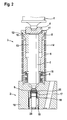
- hydraulic coupler unit 3 comprises two guided in a coupler body 20 piston, a valve piston 7 having a first diameter D 1 and a Coupler piston 22 having a second diameter D 2 , wherein D 1 ⁇ D 2 , so that according to the diameter ratio, a translation of the force and the stroke of an actuator 1 via a formed between the two pistons 7, 22 coupler gap 23, which is provided with a hydraulic fluid is filled.
- the coupler body 20 serves to guide the two pistons 7, 22 and is therefore adapted to the inner circumference of the respective piston diameters. With a radially extending collar surface of the coupler body rests against a valve plate 16, in which a control valve 2 is received.
- the valve seat facing away end is guided in a sleeve 19 and limited together with the sleeve 19 and the valve plate 16, a low-pressure space 24, so that guided in the sleeve 19 portion of the closing element 6 of the control valve 2 is not acted upon by the system pressure.
- a compressive force is required, which essentially corresponds to the spring force of a helical spring 18, by means of which the closing element 6 is biased relative to the valve seat 25.
- the coil spring 18 is supported on the one hand on the sleeve 19, on the other hand on a spring collar 17 of the closing element 6.
- the valve piston 7 is also biased by a coil spring against the closing element 6.
- the helical spring is for this purpose supported on the valve piston 7 and on an inner peripheral side radially extending shoulder of the coupler body.
- a second spring element 9 is provided in the form of a spring sleeve, by means of which the coupler piston 22 is biased against an adjusting piece 4 and thus relative to the actuator unit 1.
- the spring sleeve is supported on the one hand on a radially extending collar surface of the coupler body 20, on the other hand on a shim 21, which in turn rests against a circumferential radial collar surface of the coupler piston 22.
- the shim 21 serves to adjust the spring force since the different collar heights of the coupler body 20 and the coupler piston 22 are subject to tolerances.
- the hydraulic coupler unit 3 of a fuel injector according to the invention has only one valve piston 7 (see FIG Fig. 2 and 3 ).
- the arrangement of a second piston 22 and a coupler body 20 according to the example described above is deliberately omitted.
- the translation is thus in the ratio 1: 1.
- the control valve 2 is in turn pressure balanced, because the closing member 6 of the control valve 2 is guided in a sleeve 19, which define a low pressure space 24 together with the valve plate 16, an amplification of the actuator force or deshubes is not required.
- a coupler gap 23 is now formed between a valve piston 7 and 4 setting piece pressure chamber 10 which is bounded radially by a coupler sleeve 8.
- the valve piston 7 is movably guided.
- the guide gap 13 is designed with only a small clearance and in the present example is about 4 ⁇ m.
- the coupler sleeve 8 is further provided with a biting edge with which the coupler sleeve 8 rests sealingly on the adjusting piece 4.
- the necessary surface pressure is effected by a second spring element 9, by means of which the coupler sleeve 8 is biased against the adjusting piece 4.
- the second spring element 9 is also in this example a spring sleeve which is supported on the one hand directly to the valve plate 16, on the other hand to the coupler sleeve 8.
- the coupler sleeve 8 has for this purpose a collar 12 with a radially extending collar surface. The distance between this collar surface and the adjoining adjoining 4 biting edge is the only tolerant degree that affects the spring force. Since the influence is minimal, a dial 21 has also been dispensed with in the case of the hydraulic coupler unit 3 according to the invention. By waiving one Second piston 22 and a shim 21, the length of the coupler unit 3 according to the embodiment of Fig. 2 by 4.5 mm compared to the known design accordingly Fig. 1 be shortened.
- the hydraulic coupler unit 3 of the Fig. 2 a centering sleeve 14 for centering the coupler sleeve 8 and thus indirectly for centering and guiding the valve piston 7.
- the hydraulic coupler unit 3 of the Fig. 1 also has the centering sleeve 14 of the hydraulic coupler unit 3 of Fig. 2 an inner peripheral side radially extending shoulder 15, on which one end of the first spring element 5 is supported, by means of which the valve piston 7 is biased against the closing element 6 of the control valve 2.
- a further centering of the coupler sleeve 8 and thus indirectly also of the valve piston 7 takes place in that the adjusting piece 4 is at least partially embedded in an inner peripheral side recess of the coupler sleeve so that it rests against an inner peripheral side radially extending shoulder 11 of the coupler sleeve 8.
- the centering sleeve can also be reduced to an annular body, which surrounds only the valve piston 7 in the region of the valve plate 16 and this centered as a result or leads.
- the first spring element 5 has an axial position, so that it is supported on one side on the coupler sleeve 8.
- the embodiment differs Fig. 3 not from the Fig. 2 , However, the reduction of the centering sleeve 14 allows an applied to the valve piston 7 annular body a reduction in length of the coupler unit 3 of up to 6.5 mm.
- valve plate 16 can also be equipped with a collar or shoulder which allows axial guidance of the valve piston 7.
Landscapes
- Engineering & Computer Science (AREA)
- Chemical & Material Sciences (AREA)
- Combustion & Propulsion (AREA)
- Mechanical Engineering (AREA)
- General Engineering & Computer Science (AREA)
- Fuel-Injection Apparatus (AREA)
Abstract
Description
Die Erfindung betrifft einen Kraftstoffinjektor zum Einspritzen von Kraftstoff in einen Brennraum einer Brennkraftmaschine nach dem Oberbegriff des Anspruchs 1.The invention relates to a fuel injector for injecting fuel into a combustion chamber of an internal combustion engine according to the preamble of claim 1.
Derartige Kraftstoffinjektoren sind aus dem Stand der Technik bekannt. Die Druckschrift
Ein Kraftstoffinjektor der vorstehend beschriebenen Art besitzt aufgrund seines komplexen Aufbaus eine bestimmte Gesamtbaulänge. Er ist damit gegebenenfalls nicht in allen Brennkraftmaschinen einsetzbar. Es besteht daher ein allgemeines Interesse, die Gesamtbaulänge eines Kraftstoffinjektors zu reduzieren.A fuel injector of the type described above has a certain overall construction length due to its complex structure. He may therefore not be used in all internal combustion engines. There is therefore a general interest in reducing the overall construction length of a fuel injector.
Aufgabe der vorliegenden Erfindung ist es, einen solchen längenoptimierten Kraftstoffinjektor mit einer hydraulischen Kopplereinheit anzugeben, der zugleich einfach und kostengünstig herzustellen ist.Object of the present invention is to provide such a length-optimized fuel injector with a hydraulic coupler unit, which is also easy and inexpensive to manufacture.
Zur Lösung der Aufgabe wird ein Kraftstoffinjektor mit den Merkmalen des Anspruchs 1 vorgeschlagen. Vorteilhafte Weiterbildungen der Erfindungen sind in den Unteransprüchen angegeben.To solve the problem, a fuel injector with the features of claim 1 is proposed. Advantageous developments of the inventions are specified in the subclaims.
Der vorgeschlagene Kraftstoffinjektor umfasst eine Aktor-Einheit und eine hydraulische Kopplereinheit, die über ein Einstellstück mit der Aktor-Einheit in Verbindung steht. Die hydraulische Kopplereinheit umfasst einen axial verschiebbar geführten und mittels eines ersten Federelementes vorgespannten Ventilkolben und erfindungsgemäß ferner eine Kopplerhülse, die mittels eines zweiten Federelementes gegen das Einstellstück vorgespannt ist und gemeinsam mit dem Ventilkolben und dem Einstellstück einen Druckraum begrenzt. Im Unterschied zur hydraulischen Kopplereinheit des eingangs beschriebenen und aus dem Stand der Technik bekannten Injektors weist die hydraulische Kopplereinheit des erfindungsgemäßen Kraftstoffinjektors lediglich einen Kolben auf. In Ermangelung eines zweiten Kolbens und eines zwischen den Kolben ausgebildeten Kopplerspaltes dient der zwischen Ventilkolben, Einstellstück und Kopplerhülse ausgebildete Druckraum als hydraulischer Koppler. Die Übersetzung erfolgt im Verhältnis 1:1, das heißt es findet keine Verstärkung des Aktorhubes statt. Bevorzugt weist der erfindungsgemäße Kraftstoffinjektor daher ein druckausgeglichenes Steuerventil auf, dessen Betätigung im Wesentlichen systemdruckunabhängig erfolgt und somit eine geringere Druckkraft erfordert. Das Steuerventil kann beispielsweise dadurch druckausgeglichen sein, dass das Ventilschließglied des Steuerventils in einer Hülse geführt ist, wobei Ventilschließglied und Hülse einen Druckraum begrenzen, der stets druckentlastet ist. Ein druckausgeglichenes Steuerventil ist Gegenstand einer anderen Anmeldung derselben Anmelderin und soll daher im Rahmen dieser Anmeldung nicht weiter vertieft werden.The proposed fuel injector comprises an actuator unit and a hydraulic coupler unit, which communicates via an adjusting piece with the actuator unit. The hydraulic coupler unit comprises an axially displaceably guided and biased by a first spring element valve piston and according to the invention further comprises a coupler sleeve which is biased by a second spring element against the setting piece and limited together with the valve piston and the adjusting piece a pressure chamber. In contrast to the hydraulic coupler unit of the injector described above and known from the prior art, the hydraulic coupler unit of the fuel injector according to the invention has only one piston. In the absence of a second piston and a coupler gap formed between the pistons, the pressure space formed between the valve piston, the adjusting piece and the coupler sleeve serves as a hydraulic coupler. The translation takes place in a ratio of 1: 1, that is, there is no reinforcement of Aktorhubes instead. The fuel injector according to the invention therefore preferably has one pressure balanced control valve, whose operation is essentially independent of system pressure and thus requires a lower pressure force. The control valve may, for example, be pressure balanced in that the valve closure member of the control valve is guided in a sleeve, wherein valve closure member and sleeve define a pressure chamber, which is always depressurized. A pressure balanced control valve is the subject of another application of the same applicant and should therefore not be further explored in the context of this application.
Indem auf die Anordnung eines zweiten Kolbens verzichtet wird, kann die Baulänge der hydraulischen Kopplereinheit und damit die Gesamtlänge des erfindungsgemäßen Kraftstoffinjektors deutlich reduziert werden. Gegebenenfalls kann zur Kompensation des entfallenen zweiten Kolbens eine Verlängerung des Ventilkolbens erforderlich sein, doch selbst dann sind Längenreduzierungen der Kopplereinheit bis etwa 6,5 mm möglich.By dispensing with the arrangement of a second piston, the overall length of the hydraulic coupler unit and thus the total length of the fuel injector according to the invention can be significantly reduced. Optionally, an extension of the valve piston may be required to compensate for the omitted second piston, but even then length reductions of the coupler unit to about 6.5 mm are possible.
Des Weiteren wird bei dem erfindungsgemäßen Kraftstoffinjektor im Unterschied zu dem eingangs beschriebenen und aus dem Stand der Technik bekannten Injektor auf eine hochgenaue Führung, beispielsweise in Form eines Kopplerkörpers, verzichtet. Dies trägt zur Vereinfachung der hydraulischen Kopplereinheit und damit zur kostengünstigen Herstellung des Kraftstoffinjektors bei. Darüber hinaus kann bei dem erfindungsgemäßen Kraftstoffinjektor auf die Anordnung einer Einstellscheibe zur Einstellung der Federkraft der Federhülse und damit zum Ausgleich von Längentoleranzen verzichtet werden, da zum Einen die in die Federkrafttoleranzen eingehenden Maße reduziert werden, zum Anderen die Federkraft nicht mehr von toleranzbehafteten Bundhöhen abhängig ist. Dadurch wird der Aufbau eines erfindungsgemäßen Kraftstoffinjektors weiter vereinfacht und die Kosten optimiert.Furthermore, in the fuel injector according to the invention, in contrast to the injector described above and known from the prior art, a highly accurate guide, for example in the form of a coupler body, is dispensed with. This contributes to the simplification of the hydraulic coupler unit and thus to the cost-effective production of the fuel injector. In addition, in the fuel injector according to the invention can be dispensed with the arrangement of a shim for adjusting the spring force of the spring sleeve and thus to compensate for length tolerances, since on the one hand, the incoming in the spring force tolerances are reduced, on the other hand, the spring force is no longer dependent on tolerances collar heights , As a result, the structure of a fuel injector according to the invention is further simplified and the costs optimized.
Nach einer bevorzugten Ausführungsform ist zur Abdichtung des Kopplerspaltes, das heißt des Druckraumes zwischen der Kopplerhülse, dem Einstellstück und dem Ventilkolben, die an dem Einstellstück dichtend anliegende Fläche der Kopplerhülse mit einer Beißkante versehen. Die erforderliche Flächenpressung wird durch das zweite Federelement bewirkt, das die Kopplerhülse in Axialrichtung mit einer Druckkraft beaufschlagt und somit in dichtender Anlage mit dem Einstellstück hält.According to a preferred embodiment, for sealing the coupler gap, that is, the pressure space between the coupler sleeve, the adjusting piece and the valve piston, which is provided on the adjusting piece sealingly fitting surface of the coupler sleeve with a biting edge. The required surface pressure is effected by the second spring element, which acts on the coupler sleeve in the axial direction with a compressive force and thus holds in sealing contact with the setting piece.
Nach einer weiteren bevorzugten Ausführungsform besitzt die Kopplerhülse innenumfangsseitig einen umlaufenden radialen Absatz, mit dem die Kopplerhülse dichtend am Einstellstück anliegt. Bevorzugt ist daher der radiale Absatz mit einer Beißkante versehen. Der sich an den radialen Absatz anschließende Bereich weist vorzugsweise einen Innendurchmesser auf, der geringfügig größer als der Außendurchmesser des Einstellstückes ist, so dass die über das Einstellstück geführte Kopplerhülse eine Zentrierung erfährt.According to a further preferred embodiment, the coupler sleeve on the inner peripheral side has a circumferential radial shoulder, with which the coupler sleeve bears sealingly on the adjusting piece. Preferably, therefore, the radial shoulder is provided with a biting edge. The adjoining the radial shoulder region preferably has an inner diameter which is slightly larger than the outer diameter of the adjusting piece, so that the guided over the adjusting coupler sleeve undergoes a centering.
Weiterhin bevorzugt besitzt die Kopplerhülse einen nach radial außen geführten Bund zur Auflage des zweiten Federelementes, wobei das zweite Federelement vorzugsweise eine Federhülse ist. Während das eine Ende des zweiten Federelementes am Bund der Kopplerhülse abgestützt ist, liegt das andere Ende bevorzugt an einer das Steuerventil aufnehmenden Ventilplatte auf. Damit stellt der Abstand zwischen Bundfläche und Beißkante der Kopplerhülse das einzige die Federkraft des zweiten Federelementes beeinflussende Maß dar. Da der Einfluss minimal ist, kann die im Zusammenhang mit dem Stand der Technik bereits erwähnte Einstellscheibe zur Einstellung der Federkraft entfallen. Damit ist auch der aufwendige Einstellprozess selbst entbehrlich. Durch diese Maßnahme vereinfacht sich nicht nur der Aufbau der hydraulischen Kopplereinheit, sondern ermöglicht durch den Verzicht auf eine Einstellscheibe eine weitere Reduzierung der Baulänge der Kopplereinheit und damit der Gesamtlänge des Kraftstoffinjektors.Further preferably, the coupler sleeve has a radially outwardly guided collar for supporting the second spring element, wherein the second spring element is preferably a spring sleeve. While one end of the second spring element is supported on the collar of the coupler sleeve, the other end is preferably located on a valve plate receiving the control valve. Thus, the distance between the collar surface and the biting edge of the coupler sleeve is the only measure influencing the spring force of the second spring element. Since the influence is minimal, the adjusting disk already mentioned in connection with the prior art can be omitted for adjusting the spring force. Thus, the complex adjustment process itself is unnecessary. By this measure, not only simplifies the construction of the hydraulic coupler unit, but allows by dispensing with a dial another Reduction in the length of the coupler unit and thus the total length of the fuel injector.
Vorteilhafterweise beträgt der Führungsspalt zwischen Kopplerhülse und Ventilkolben weniger als 10 µm, vorzugsweise weniger als 5 µm. Dadurch ist eine hochgenaue Führung des Ventilkolbens über die Kopplerhülse sichergestellt. Da die Kopplerhülse vorzugsweise derart ausgebildet ist, dass sie lediglich einen Abschnitt des Ventilkolbens umfasst, und zwar das dem Einstellstück zugewandte Ende, können zur Führung des anderen, dem Steuerventil zugewandten Endes des Ventilkolbens weitere Maßnahmen getroffen werden. Beispielsweise kann die das Steuerventil aufnehmende Ventilplatte mit einem als Führung dienenden Kragen ausgebildet sein. Allerdings erfordert die Ausbildung der Ventilplatte mit einem Kragen einen höheren fertigungstechnischen Aufwand. Nachfolgend werden daher alternative Maßnahmen aufgezeigt.Advantageously, the guide gap between coupler sleeve and valve piston is less than 10 microns, preferably less than 5 microns. This ensures a highly accurate guidance of the valve piston via the coupler sleeve. Since the coupler sleeve is preferably designed such that it comprises only a portion of the valve piston, namely the end facing the adjusting piece, further measures can be taken to guide the other, the control valve facing the end of the valve piston. For example, the control valve receiving valve plate may be formed with a serving as a guide collar. However, the formation of the valve plate with a collar requires a higher manufacturing effort. Subsequently, alternative measures are shown.
Eine gewisse Führung erfährt der Ventilkolben beispielsweise durch die in Axialrichtung wirkende Federkraft des ersten Federelementes, mittels dessen der Ventilkolben gegenüber dem Schließelement des Steuerventils vorgespannt ist. Hierzu ist vorzugsweise das erste Federelement einerseits an der Kopplerhülse, andererseits am Ventilkolben abgestützt. Vorteilhafterweise ist der Ventilkolben mit einer Bundhülse ausgestattet, an deren radial verlaufenden Bundfläche die Schraubenfeder abgestützt ist. Weiterhin vorzugsweise ist das erste Federelement eine Schraubenfeder.A certain guidance experiences the valve piston, for example, by the spring force acting in the axial direction of the first spring element, by means of which the valve piston is biased against the closing element of the control valve. For this purpose, preferably the first spring element is supported on the one hand on the coupler sleeve, on the other hand on the valve piston. Advantageously, the valve piston is equipped with a collar sleeve, on the radially extending collar surface, the coil spring is supported. Further preferably, the first spring element is a helical spring.
Des Weiteren kann die hydraulische Kopplereinheit eine Zentrierhülse zur Zentrierung der Kopplerhülse und/oder des Ventilkolbens umfassen. Sofern der Ventilkolben über die Zentrierhülse eine Zentrierung erfährt, erfährt er auch eine Führung, da der Ventilkolben gegenüber der Zentrierhülse bevorzugt axial beweglich angeordnet ist. Die Zentrierhülse kann beispielsweise anstelle eines Kragens an der Oberseite der Ventilplatte angeordnet sein. Die Ventilplatte kann zur Aufnahme und Lagefixierung der Zentrierhülse, zumindest in radialer Richtung, ferner eine konzentrische Bohrung besitzen, in welche die Zentrierhülse eingesetzt ist.Furthermore, the hydraulic coupler unit may comprise a centering sleeve for centering the coupler sleeve and / or the valve piston. If the valve piston experiences centering via the centering sleeve, it also experiences a guide, since the valve piston is preferably arranged to be axially movable relative to the centering sleeve. The centering sleeve can be arranged for example instead of a collar on the upper side of the valve plate. The valve plate can for receiving and fixing the position of the centering, at least in the radial direction, further have a concentric bore into which the centering sleeve is inserted.
Nach einer ersten bevorzugten Ausführungsform erstreckt sich die Zentrierhülse von der Ventilplatte bis zur Kopplerhülse bzw. darüber hinaus, so dass vorrangig die Kopplerhülse und mittelbar über die Kopplerhülse der Ventilkolben eine Zentrierung bzw. Führung erfährt. Die Zentrierhülse besitzt vorzugsweise innenumfangseitig einen umlaufenden radialen Absatz, an dem das erste Federelement abgestützt ist. Zur Ausbildung eines solchen Absatzes kann die Zentrierhülse beispielsweise Abschnitte mit unterschiedlichen Innendurchmessern aufweisen. Außenumfangseitig weist die Zentrierhülse bevorzugt eine zylindrische Mantelfläche auf.According to a first preferred embodiment, the centering sleeve extends from the valve plate to the coupler sleeve or beyond, so that primarily the coupler sleeve and indirectly via the coupler sleeve of the valve piston undergoes a centering or guiding. The centering sleeve preferably has on the inner peripheral side a circumferential radial shoulder on which the first spring element is supported. To form such a shoulder, the centering sleeve may for example have sections with different inner diameters. On the outer circumference side, the centering sleeve preferably has a cylindrical lateral surface.
Bevorzugte Ausführungsformen der Erfindung werden nachfolgend anhand der Zeichnungen näher erläutert. Es zeigen:
-
Fig. 1 einen Längsschnitt durch die hydraulische Kopplereinheit eines aus dem Stand der Technik bekannten Kraftstoffinjektors, -
Fig. 2 einen Längsschnitt durch die hydraulische Kopplereinheit einer ersten Ausführungsform eines erfindungsgemäßen Kraftstoffinjektors und -
Fig. 3 einen Längsschnitt durch die hydraulische Kopplereinheit einer zweiten Ausführungsform eines erfindungsgemäßen Kraftstoffinjektors.
-
Fig. 1 a longitudinal section through the hydraulic coupler unit of a known from the prior art fuel injector, -
Fig. 2 a longitudinal section through the hydraulic coupler unit of a first embodiment of a fuel injector according to the invention and -
Fig. 3 a longitudinal section through the hydraulic coupler unit of a second embodiment of a fuel injector according to the invention.
Die in
Im Unterschied zur der hydraulischen Kopplereinheit 3 der
Anstelle eines Kopplerkörpers 20 weist die hydraulische Kopplereinheit 3 der
Eine weitere Zentrierung der Kopplerhülse 8 und damit mittelbar auch des Ventilkolbens 7 erfolgt dadurch, dass das Einstellstück 4 zumindest teilweise in eine innenumfangseitige Ausnehmung der Kopplerhülse eingelassen ist, so dass sie an einem innenumfangseitig radial verlaufenden Absatz 11 der Kopplerhülse 8 anliegt.A further centering of the coupler sleeve 8 and thus indirectly also of the
Da eine Zentrierung der Kopplerhülse 8 über die Zentrierhülse 14 nicht unbedingt erforderlich ist, kann gemäß dem in
Alternativ zur Anordnung einer als Ringkörper ausgebildeten Zentrierhülse 14 kann auch die Ventilplatte 16 mit einem Kragen oder Absatz ausgestattet sein, der eine axiale Führung des Ventilkolbens 7 ermöglicht.As an alternative to the arrangement of a centering
Claims (8)
dadurch gekennzeichnet,
dass die hydraulische Kopplereinheit (3) ferner eine Kopplerhülse (8) umfasst, die mittels eines zweiten Federelementes (9) gegen das Einstellstück (4) vorgespannt ist und gemeinsam mit dem Ventilkolben (7) und dem Einstellstück (4) einen Druckraum (10) begrenzt.Fuel injector for injecting fuel into a combustion chamber of an internal combustion engine with an actuator unit (1) for actuating a control valve (2) and with a hydraulic coupler unit (3) via an adjusting piece (4) with the actuator unit (1) in Connection stands and an axially displaceably guided and by means of a first spring element (5) against a closing element (6) of the control valve (2) biased valve piston (7),
characterized,
in that the hydraulic coupler unit (3) furthermore comprises a coupler sleeve (8) which is prestressed against the adjusting piece (4) by means of a second spring element (9) and together with the valve piston (7) and the adjusting piece (4) has a pressure chamber (10). limited.
Applications Claiming Priority (1)
| Application Number | Priority Date | Filing Date | Title |
|---|---|---|---|
| DE200910000875 DE102009000875A1 (en) | 2009-02-16 | 2009-02-16 | fuel injector |
Publications (2)
| Publication Number | Publication Date |
|---|---|
| EP2218906A1 true EP2218906A1 (en) | 2010-08-18 |
| EP2218906B1 EP2218906B1 (en) | 2013-02-20 |
Family
ID=41718754
Family Applications (1)
| Application Number | Title | Priority Date | Filing Date |
|---|---|---|---|
| EP20090180310 Not-in-force EP2218906B1 (en) | 2009-02-16 | 2009-12-22 | Fuel injector |
Country Status (2)
| Country | Link |
|---|---|
| EP (1) | EP2218906B1 (en) |
| DE (1) | DE102009000875A1 (en) |
Cited By (2)
| Publication number | Priority date | Publication date | Assignee | Title |
|---|---|---|---|---|
| WO2012059265A1 (en) * | 2010-11-04 | 2012-05-10 | Robert Bosch Gmbh | Fuel injector |
| EP3035520A1 (en) * | 2014-12-19 | 2016-06-22 | Robert Bosch Gmbh | Hydraulic coupler unit for controlling a valve |
Citations (3)
| Publication number | Priority date | Publication date | Assignee | Title |
|---|---|---|---|---|
| DE102004044812A1 (en) * | 2004-09-16 | 2006-03-23 | Robert Bosch Gmbh | Control valve of an injection nozzle for an internal combustion engine |
| DE102006042601A1 (en) | 2006-09-11 | 2008-03-27 | Robert Bosch Gmbh | Injector for injecting fuel |
| EP1916410A2 (en) * | 2006-10-20 | 2008-04-30 | Robert Bosch Gmbh | Pilot valve for an injector and injector |
-
2009
- 2009-02-16 DE DE200910000875 patent/DE102009000875A1/en not_active Withdrawn
- 2009-12-22 EP EP20090180310 patent/EP2218906B1/en not_active Not-in-force
Patent Citations (3)
| Publication number | Priority date | Publication date | Assignee | Title |
|---|---|---|---|---|
| DE102004044812A1 (en) * | 2004-09-16 | 2006-03-23 | Robert Bosch Gmbh | Control valve of an injection nozzle for an internal combustion engine |
| DE102006042601A1 (en) | 2006-09-11 | 2008-03-27 | Robert Bosch Gmbh | Injector for injecting fuel |
| EP1916410A2 (en) * | 2006-10-20 | 2008-04-30 | Robert Bosch Gmbh | Pilot valve for an injector and injector |
Cited By (4)
| Publication number | Priority date | Publication date | Assignee | Title |
|---|---|---|---|---|
| WO2012059265A1 (en) * | 2010-11-04 | 2012-05-10 | Robert Bosch Gmbh | Fuel injector |
| CN103189635A (en) * | 2010-11-04 | 2013-07-03 | 罗伯特·博世有限公司 | Fuel injector |
| CN103189635B (en) * | 2010-11-04 | 2016-08-31 | 罗伯特·博世有限公司 | Fuel injector |
| EP3035520A1 (en) * | 2014-12-19 | 2016-06-22 | Robert Bosch Gmbh | Hydraulic coupler unit for controlling a valve |
Also Published As
| Publication number | Publication date |
|---|---|
| DE102009000875A1 (en) | 2010-08-19 |
| EP2218906B1 (en) | 2013-02-20 |
Similar Documents
| Publication | Publication Date | Title |
|---|---|---|
| EP1989436B1 (en) | Fuel injection device for an internal combustion engine | |
| EP1477666B1 (en) | Supply pump, in particular high pressure fuel pump for internal combustion engines | |
| EP2715103B1 (en) | Nozzle assembly for a fuel injector, and fuel injector | |
| WO2011023467A1 (en) | Fuel injection valve | |
| EP2218906B1 (en) | Fuel injector | |
| WO2011042296A1 (en) | Fuel injection valve and production thereof | |
| EP2226490B1 (en) | Fuel injector | |
| EP3060789B1 (en) | Fuel injector | |
| EP1873393A1 (en) | Injector | |
| EP2957760B1 (en) | Nozzle assembly for a fuel injector and fuel injector | |
| EP2905458B1 (en) | Nozzle assembly for a fuel injector and fuel injector | |
| WO2005017323A1 (en) | Hydraulic support element | |
| WO2011160900A1 (en) | Fuel injection device comprising a hydraulic coupler | |
| EP2955366B1 (en) | Nozzle assembly for a fuel injector and fuel injector | |
| EP3035520B1 (en) | Hydraulic coupler unit for controlling a valve | |
| EP3303817B1 (en) | Common-rail-injector | |
| EP2884088B1 (en) | Fuel injector | |
| EP2366887B1 (en) | Fuel injector | |
| DE102014209997A1 (en) | Common rail injector | |
| WO2009013069A1 (en) | Fuel injector having a non-guided nozzle needle | |
| EP3358178A1 (en) | Hydraulic coupler for a piezo injector, piezo injector | |
| DE102017204644A1 (en) | Hydraulic coupler unit and fuel injector | |
| WO2013000635A1 (en) | Fuel injector |
Legal Events
| Date | Code | Title | Description |
|---|---|---|---|
| PUAI | Public reference made under article 153(3) epc to a published international application that has entered the european phase |
Free format text: ORIGINAL CODE: 0009012 |
|
| AK | Designated contracting states |
Kind code of ref document: A1 Designated state(s): AT BE BG CH CY CZ DE DK EE ES FI FR GB GR HR HU IE IS IT LI LT LU LV MC MK MT NL NO PL PT RO SE SI SK SM TR |
|
| 17P | Request for examination filed |
Effective date: 20110218 |
|
| RIC1 | Information provided on ipc code assigned before grant |
Ipc: F02M 63/00 20060101AFI20120809BHEP |
|
| GRAP | Despatch of communication of intention to grant a patent |
Free format text: ORIGINAL CODE: EPIDOSNIGR1 |
|
| GRAS | Grant fee paid |
Free format text: ORIGINAL CODE: EPIDOSNIGR3 |
|
| GRAA | (expected) grant |
Free format text: ORIGINAL CODE: 0009210 |
|
| AK | Designated contracting states |
Kind code of ref document: B1 Designated state(s): AT BE BG CH CY CZ DE DK EE ES FI FR GB GR HR HU IE IS IT LI LT LU LV MC MK MT NL NO PL PT RO SE SI SK SM TR |
|
| REG | Reference to a national code |
Ref country code: GB Ref legal event code: FG4D Free format text: NOT ENGLISH |
|
| REG | Reference to a national code |
Ref country code: CH Ref legal event code: EP |
|
| REG | Reference to a national code |
Ref country code: AT Ref legal event code: REF Ref document number: 597674 Country of ref document: AT Kind code of ref document: T Effective date: 20130315 |
|
| REG | Reference to a national code |
Ref country code: IE Ref legal event code: FG4D Free format text: LANGUAGE OF EP DOCUMENT: GERMAN |
|
| REG | Reference to a national code |
Ref country code: DE Ref legal event code: R096 Ref document number: 502009006276 Country of ref document: DE Effective date: 20130418 |
|
| REG | Reference to a national code |
Ref country code: NL Ref legal event code: VDEP Effective date: 20130220 |
|
| REG | Reference to a national code |
Ref country code: LT Ref legal event code: MG4D |
|
| PG25 | Lapsed in a contracting state [announced via postgrant information from national office to epo] |
Ref country code: SE Free format text: LAPSE BECAUSE OF FAILURE TO SUBMIT A TRANSLATION OF THE DESCRIPTION OR TO PAY THE FEE WITHIN THE PRESCRIBED TIME-LIMIT Effective date: 20130220 Ref country code: ES Free format text: LAPSE BECAUSE OF FAILURE TO SUBMIT A TRANSLATION OF THE DESCRIPTION OR TO PAY THE FEE WITHIN THE PRESCRIBED TIME-LIMIT Effective date: 20130531 Ref country code: BG Free format text: LAPSE BECAUSE OF FAILURE TO SUBMIT A TRANSLATION OF THE DESCRIPTION OR TO PAY THE FEE WITHIN THE PRESCRIBED TIME-LIMIT Effective date: 20130520 Ref country code: LT Free format text: LAPSE BECAUSE OF FAILURE TO SUBMIT A TRANSLATION OF THE DESCRIPTION OR TO PAY THE FEE WITHIN THE PRESCRIBED TIME-LIMIT Effective date: 20130220 Ref country code: IS Free format text: LAPSE BECAUSE OF FAILURE TO SUBMIT A TRANSLATION OF THE DESCRIPTION OR TO PAY THE FEE WITHIN THE PRESCRIBED TIME-LIMIT Effective date: 20130620 Ref country code: NO Free format text: LAPSE BECAUSE OF FAILURE TO SUBMIT A TRANSLATION OF THE DESCRIPTION OR TO PAY THE FEE WITHIN THE PRESCRIBED TIME-LIMIT Effective date: 20130520 |
|
| PG25 | Lapsed in a contracting state [announced via postgrant information from national office to epo] |
Ref country code: SI Free format text: LAPSE BECAUSE OF FAILURE TO SUBMIT A TRANSLATION OF THE DESCRIPTION OR TO PAY THE FEE WITHIN THE PRESCRIBED TIME-LIMIT Effective date: 20130220 Ref country code: LV Free format text: LAPSE BECAUSE OF FAILURE TO SUBMIT A TRANSLATION OF THE DESCRIPTION OR TO PAY THE FEE WITHIN THE PRESCRIBED TIME-LIMIT Effective date: 20130220 Ref country code: PL Free format text: LAPSE BECAUSE OF FAILURE TO SUBMIT A TRANSLATION OF THE DESCRIPTION OR TO PAY THE FEE WITHIN THE PRESCRIBED TIME-LIMIT Effective date: 20130220 Ref country code: GR Free format text: LAPSE BECAUSE OF FAILURE TO SUBMIT A TRANSLATION OF THE DESCRIPTION OR TO PAY THE FEE WITHIN THE PRESCRIBED TIME-LIMIT Effective date: 20130521 Ref country code: PT Free format text: LAPSE BECAUSE OF FAILURE TO SUBMIT A TRANSLATION OF THE DESCRIPTION OR TO PAY THE FEE WITHIN THE PRESCRIBED TIME-LIMIT Effective date: 20130620 Ref country code: FI Free format text: LAPSE BECAUSE OF FAILURE TO SUBMIT A TRANSLATION OF THE DESCRIPTION OR TO PAY THE FEE WITHIN THE PRESCRIBED TIME-LIMIT Effective date: 20130220 |
|
| PG25 | Lapsed in a contracting state [announced via postgrant information from national office to epo] |
Ref country code: HR Free format text: LAPSE BECAUSE OF FAILURE TO SUBMIT A TRANSLATION OF THE DESCRIPTION OR TO PAY THE FEE WITHIN THE PRESCRIBED TIME-LIMIT Effective date: 20130220 |
|
| PG25 | Lapsed in a contracting state [announced via postgrant information from national office to epo] |
Ref country code: RO Free format text: LAPSE BECAUSE OF FAILURE TO SUBMIT A TRANSLATION OF THE DESCRIPTION OR TO PAY THE FEE WITHIN THE PRESCRIBED TIME-LIMIT Effective date: 20130220 Ref country code: CZ Free format text: LAPSE BECAUSE OF FAILURE TO SUBMIT A TRANSLATION OF THE DESCRIPTION OR TO PAY THE FEE WITHIN THE PRESCRIBED TIME-LIMIT Effective date: 20130220 Ref country code: DK Free format text: LAPSE BECAUSE OF FAILURE TO SUBMIT A TRANSLATION OF THE DESCRIPTION OR TO PAY THE FEE WITHIN THE PRESCRIBED TIME-LIMIT Effective date: 20130220 Ref country code: SK Free format text: LAPSE BECAUSE OF FAILURE TO SUBMIT A TRANSLATION OF THE DESCRIPTION OR TO PAY THE FEE WITHIN THE PRESCRIBED TIME-LIMIT Effective date: 20130220 Ref country code: EE Free format text: LAPSE BECAUSE OF FAILURE TO SUBMIT A TRANSLATION OF THE DESCRIPTION OR TO PAY THE FEE WITHIN THE PRESCRIBED TIME-LIMIT Effective date: 20130220 Ref country code: NL Free format text: LAPSE BECAUSE OF FAILURE TO SUBMIT A TRANSLATION OF THE DESCRIPTION OR TO PAY THE FEE WITHIN THE PRESCRIBED TIME-LIMIT Effective date: 20130220 |
|
| PLBE | No opposition filed within time limit |
Free format text: ORIGINAL CODE: 0009261 |
|
| STAA | Information on the status of an ep patent application or granted ep patent |
Free format text: STATUS: NO OPPOSITION FILED WITHIN TIME LIMIT |
|
| PG25 | Lapsed in a contracting state [announced via postgrant information from national office to epo] |
Ref country code: IT Free format text: LAPSE BECAUSE OF FAILURE TO SUBMIT A TRANSLATION OF THE DESCRIPTION OR TO PAY THE FEE WITHIN THE PRESCRIBED TIME-LIMIT Effective date: 20130220 |
|
| 26N | No opposition filed |
Effective date: 20131121 |
|
| REG | Reference to a national code |
Ref country code: DE Ref legal event code: R097 Ref document number: 502009006276 Country of ref document: DE Effective date: 20131121 |
|
| BERE | Be: lapsed |
Owner name: ROBERT BOSCH G.M.B.H. Effective date: 20131231 |
|
| REG | Reference to a national code |
Ref country code: CH Ref legal event code: PL |
|
| GBPC | Gb: european patent ceased through non-payment of renewal fee |
Effective date: 20131222 |
|
| PG25 | Lapsed in a contracting state [announced via postgrant information from national office to epo] |
Ref country code: MC Free format text: LAPSE BECAUSE OF FAILURE TO SUBMIT A TRANSLATION OF THE DESCRIPTION OR TO PAY THE FEE WITHIN THE PRESCRIBED TIME-LIMIT Effective date: 20130220 Ref country code: LU Free format text: LAPSE BECAUSE OF FAILURE TO SUBMIT A TRANSLATION OF THE DESCRIPTION OR TO PAY THE FEE WITHIN THE PRESCRIBED TIME-LIMIT Effective date: 20131222 |
|
| REG | Reference to a national code |
Ref country code: IE Ref legal event code: MM4A |
|
| PG25 | Lapsed in a contracting state [announced via postgrant information from national office to epo] |
Ref country code: IE Free format text: LAPSE BECAUSE OF NON-PAYMENT OF DUE FEES Effective date: 20131222 Ref country code: LI Free format text: LAPSE BECAUSE OF NON-PAYMENT OF DUE FEES Effective date: 20131231 Ref country code: BE Free format text: LAPSE BECAUSE OF NON-PAYMENT OF DUE FEES Effective date: 20131231 Ref country code: CH Free format text: LAPSE BECAUSE OF NON-PAYMENT OF DUE FEES Effective date: 20131231 |
|
| PG25 | Lapsed in a contracting state [announced via postgrant information from national office to epo] |
Ref country code: GB Free format text: LAPSE BECAUSE OF NON-PAYMENT OF DUE FEES Effective date: 20131222 |
|
| PG25 | Lapsed in a contracting state [announced via postgrant information from national office to epo] |
Ref country code: SM Free format text: LAPSE BECAUSE OF FAILURE TO SUBMIT A TRANSLATION OF THE DESCRIPTION OR TO PAY THE FEE WITHIN THE PRESCRIBED TIME-LIMIT Effective date: 20130220 |
|
| PG25 | Lapsed in a contracting state [announced via postgrant information from national office to epo] |
Ref country code: CY Free format text: LAPSE BECAUSE OF FAILURE TO SUBMIT A TRANSLATION OF THE DESCRIPTION OR TO PAY THE FEE WITHIN THE PRESCRIBED TIME-LIMIT Effective date: 20130220 Ref country code: TR Free format text: LAPSE BECAUSE OF FAILURE TO SUBMIT A TRANSLATION OF THE DESCRIPTION OR TO PAY THE FEE WITHIN THE PRESCRIBED TIME-LIMIT Effective date: 20130220 |
|
| PG25 | Lapsed in a contracting state [announced via postgrant information from national office to epo] |
Ref country code: MK Free format text: LAPSE BECAUSE OF FAILURE TO SUBMIT A TRANSLATION OF THE DESCRIPTION OR TO PAY THE FEE WITHIN THE PRESCRIBED TIME-LIMIT Effective date: 20130220 Ref country code: HU Free format text: LAPSE BECAUSE OF FAILURE TO SUBMIT A TRANSLATION OF THE DESCRIPTION OR TO PAY THE FEE WITHIN THE PRESCRIBED TIME-LIMIT; INVALID AB INITIO Effective date: 20091222 |
|
| PG25 | Lapsed in a contracting state [announced via postgrant information from national office to epo] |
Ref country code: MT Free format text: LAPSE BECAUSE OF FAILURE TO SUBMIT A TRANSLATION OF THE DESCRIPTION OR TO PAY THE FEE WITHIN THE PRESCRIBED TIME-LIMIT Effective date: 20130220 |
|
| REG | Reference to a national code |
Ref country code: FR Ref legal event code: PLFP Year of fee payment: 7 |
|
| REG | Reference to a national code |
Ref country code: AT Ref legal event code: MM01 Ref document number: 597674 Country of ref document: AT Kind code of ref document: T Effective date: 20141222 |
|
| PG25 | Lapsed in a contracting state [announced via postgrant information from national office to epo] |
Ref country code: AT Free format text: LAPSE BECAUSE OF NON-PAYMENT OF DUE FEES Effective date: 20141222 |
|
| REG | Reference to a national code |
Ref country code: FR Ref legal event code: PLFP Year of fee payment: 8 |
|
| REG | Reference to a national code |
Ref country code: FR Ref legal event code: PLFP Year of fee payment: 9 |
|
| PGFP | Annual fee paid to national office [announced via postgrant information from national office to epo] |
Ref country code: FR Payment date: 20181218 Year of fee payment: 10 |
|
| PGFP | Annual fee paid to national office [announced via postgrant information from national office to epo] |
Ref country code: DE Payment date: 20190221 Year of fee payment: 10 |
|
| REG | Reference to a national code |
Ref country code: DE Ref legal event code: R119 Ref document number: 502009006276 Country of ref document: DE |
|
| PG25 | Lapsed in a contracting state [announced via postgrant information from national office to epo] |
Ref country code: DE Free format text: LAPSE BECAUSE OF NON-PAYMENT OF DUE FEES Effective date: 20200701 Ref country code: FR Free format text: LAPSE BECAUSE OF NON-PAYMENT OF DUE FEES Effective date: 20191231 |