EP2218902B1 - Method for manufacturing an open/close element for balanced servo valves of a fuel injector. - Google Patents
Method for manufacturing an open/close element for balanced servo valves of a fuel injector. Download PDFInfo
- Publication number
- EP2218902B1 EP2218902B1 EP09425058A EP09425058A EP2218902B1 EP 2218902 B1 EP2218902 B1 EP 2218902B1 EP 09425058 A EP09425058 A EP 09425058A EP 09425058 A EP09425058 A EP 09425058A EP 2218902 B1 EP2218902 B1 EP 2218902B1
- Authority
- EP
- European Patent Office
- Prior art keywords
- bushing
- manufacturing
- anchor
- flange
- open
- Prior art date
- Legal status (The legal status is an assumption and is not a legal conclusion. Google has not performed a legal analysis and makes no representation as to the accuracy of the status listed.)
- Active
Links
Images


Classifications
-
- F—MECHANICAL ENGINEERING; LIGHTING; HEATING; WEAPONS; BLASTING
- F02—COMBUSTION ENGINES; HOT-GAS OR COMBUSTION-PRODUCT ENGINE PLANTS
- F02M—SUPPLYING COMBUSTION ENGINES IN GENERAL WITH COMBUSTIBLE MIXTURES OR CONSTITUENTS THEREOF
- F02M61/00—Fuel-injectors not provided for in groups F02M39/00 - F02M57/00 or F02M67/00
- F02M61/16—Details not provided for in, or of interest apart from, the apparatus of groups F02M61/02 - F02M61/14
- F02M61/168—Assembling; Disassembling; Manufacturing; Adjusting
-
- F—MECHANICAL ENGINEERING; LIGHTING; HEATING; WEAPONS; BLASTING
- F02—COMBUSTION ENGINES; HOT-GAS OR COMBUSTION-PRODUCT ENGINE PLANTS
- F02M—SUPPLYING COMBUSTION ENGINES IN GENERAL WITH COMBUSTIBLE MIXTURES OR CONSTITUENTS THEREOF
- F02M63/00—Other fuel-injection apparatus having pertinent characteristics not provided for in groups F02M39/00 - F02M57/00 or F02M67/00; Details, component parts, or accessories of fuel-injection apparatus, not provided for in, or of interest apart from, the apparatus of groups F02M39/00 - F02M61/00 or F02M67/00; Combination of fuel pump with other devices, e.g. lubricating oil pump
- F02M63/0012—Valves
- F02M63/0014—Valves characterised by the valve actuating means
- F02M63/0015—Valves characterised by the valve actuating means electrical, e.g. using solenoid
- F02M63/0017—Valves characterised by the valve actuating means electrical, e.g. using solenoid using electromagnetic operating means
- F02M63/0021—Valves characterised by the valve actuating means electrical, e.g. using solenoid using electromagnetic operating means characterised by the arrangement of mobile armatures
-
- F—MECHANICAL ENGINEERING; LIGHTING; HEATING; WEAPONS; BLASTING
- F02—COMBUSTION ENGINES; HOT-GAS OR COMBUSTION-PRODUCT ENGINE PLANTS
- F02M—SUPPLYING COMBUSTION ENGINES IN GENERAL WITH COMBUSTIBLE MIXTURES OR CONSTITUENTS THEREOF
- F02M63/00—Other fuel-injection apparatus having pertinent characteristics not provided for in groups F02M39/00 - F02M57/00 or F02M67/00; Details, component parts, or accessories of fuel-injection apparatus, not provided for in, or of interest apart from, the apparatus of groups F02M39/00 - F02M61/00 or F02M67/00; Combination of fuel pump with other devices, e.g. lubricating oil pump
- F02M63/0012—Valves
- F02M63/007—Details not provided for in, or of interest apart from, the apparatus of the groups F02M63/0014 - F02M63/0059
- F02M63/0071—Details not provided for in, or of interest apart from, the apparatus of the groups F02M63/0014 - F02M63/0059 characterised by guiding or centering means in valves including the absence of any guiding means, e.g. "flying arrangements"
-
- F—MECHANICAL ENGINEERING; LIGHTING; HEATING; WEAPONS; BLASTING
- F02—COMBUSTION ENGINES; HOT-GAS OR COMBUSTION-PRODUCT ENGINE PLANTS
- F02M—SUPPLYING COMBUSTION ENGINES IN GENERAL WITH COMBUSTIBLE MIXTURES OR CONSTITUENTS THEREOF
- F02M63/00—Other fuel-injection apparatus having pertinent characteristics not provided for in groups F02M39/00 - F02M57/00 or F02M67/00; Details, component parts, or accessories of fuel-injection apparatus, not provided for in, or of interest apart from, the apparatus of groups F02M39/00 - F02M61/00 or F02M67/00; Combination of fuel pump with other devices, e.g. lubricating oil pump
- F02M63/0012—Valves
- F02M63/007—Details not provided for in, or of interest apart from, the apparatus of the groups F02M63/0014 - F02M63/0059
- F02M63/0075—Stop members in valves, e.g. plates or disks limiting the movement of armature, valve or spring
-
- F—MECHANICAL ENGINEERING; LIGHTING; HEATING; WEAPONS; BLASTING
- F02—COMBUSTION ENGINES; HOT-GAS OR COMBUSTION-PRODUCT ENGINE PLANTS
- F02M—SUPPLYING COMBUSTION ENGINES IN GENERAL WITH COMBUSTIBLE MIXTURES OR CONSTITUENTS THEREOF
- F02M63/00—Other fuel-injection apparatus having pertinent characteristics not provided for in groups F02M39/00 - F02M57/00 or F02M67/00; Details, component parts, or accessories of fuel-injection apparatus, not provided for in, or of interest apart from, the apparatus of groups F02M39/00 - F02M61/00 or F02M67/00; Combination of fuel pump with other devices, e.g. lubricating oil pump
- F02M63/0012—Valves
- F02M63/007—Details not provided for in, or of interest apart from, the apparatus of the groups F02M63/0014 - F02M63/0059
- F02M63/0078—Valve member details, e.g. special shape, hollow or fuel passages in the valve member
- F02M63/008—Hollow valve members, e.g. members internally guided
-
- F—MECHANICAL ENGINEERING; LIGHTING; HEATING; WEAPONS; BLASTING
- F02—COMBUSTION ENGINES; HOT-GAS OR COMBUSTION-PRODUCT ENGINE PLANTS
- F02M—SUPPLYING COMBUSTION ENGINES IN GENERAL WITH COMBUSTIBLE MIXTURES OR CONSTITUENTS THEREOF
- F02M2200/00—Details of fuel-injection apparatus, not otherwise provided for
- F02M2200/80—Fuel injection apparatus manufacture, repair or assembly
- F02M2200/8084—Fuel injection apparatus manufacture, repair or assembly involving welding or soldering
-
- F—MECHANICAL ENGINEERING; LIGHTING; HEATING; WEAPONS; BLASTING
- F02—COMBUSTION ENGINES; HOT-GAS OR COMBUSTION-PRODUCT ENGINE PLANTS
- F02M—SUPPLYING COMBUSTION ENGINES IN GENERAL WITH COMBUSTIBLE MIXTURES OR CONSTITUENTS THEREOF
- F02M2200/00—Details of fuel-injection apparatus, not otherwise provided for
- F02M2200/80—Fuel injection apparatus manufacture, repair or assembly
- F02M2200/8092—Fuel injection apparatus manufacture, repair or assembly adjusting or calibration
-
- F—MECHANICAL ENGINEERING; LIGHTING; HEATING; WEAPONS; BLASTING
- F02—COMBUSTION ENGINES; HOT-GAS OR COMBUSTION-PRODUCT ENGINE PLANTS
- F02M—SUPPLYING COMBUSTION ENGINES IN GENERAL WITH COMBUSTIBLE MIXTURES OR CONSTITUENTS THEREOF
- F02M47/00—Fuel-injection apparatus operated cyclically with fuel-injection valves actuated by fluid pressure
- F02M47/02—Fuel-injection apparatus operated cyclically with fuel-injection valves actuated by fluid pressure of accumulator-injector type, i.e. having fuel pressure of accumulator tending to open, and fuel pressure in other chamber tending to close, injection valves and having means for periodically releasing that closing pressure
- F02M47/027—Electrically actuated valves draining the chamber to release the closing pressure
-
- F—MECHANICAL ENGINEERING; LIGHTING; HEATING; WEAPONS; BLASTING
- F02—COMBUSTION ENGINES; HOT-GAS OR COMBUSTION-PRODUCT ENGINE PLANTS
- F02M—SUPPLYING COMBUSTION ENGINES IN GENERAL WITH COMBUSTIBLE MIXTURES OR CONSTITUENTS THEREOF
- F02M51/00—Fuel-injection apparatus characterised by being operated electrically
- F02M51/06—Injectors peculiar thereto with means directly operating the valve needle
- F02M51/061—Injectors peculiar thereto with means directly operating the valve needle using electromagnetic operating means
- F02M51/0625—Injectors peculiar thereto with means directly operating the valve needle using electromagnetic operating means characterised by arrangement of mobile armatures
- F02M51/0635—Injectors peculiar thereto with means directly operating the valve needle using electromagnetic operating means characterised by arrangement of mobile armatures having a plate-shaped or undulated armature not entering the winding
- F02M51/066—Injectors peculiar thereto with means directly operating the valve needle using electromagnetic operating means characterised by arrangement of mobile armatures having a plate-shaped or undulated armature not entering the winding the armature and the valve being allowed to move relatively to each other or not being attached to each other
Abstract
Description
- The present invention relates to a method for manufacturing an open/close element for balanced servo valves of a fuel injector, in which the open/close element comprises a bushing designed to move for a certain axial travel along a fixed stem for opening and closing the servo valve. The invention moreover relates to an open/close element manufactured applying the aforesaid method.
- In servo valves of the type described, as for example shown in
DE 102006021741 andUS 2009/0032621 , the discharge duct of the servo valve gives out onto a lateral surface of the stem, in such a way that, in the closing position, the bushing is subject to a substantially zero axial pressure. Consequently, the servo valve is of a balanced type and requires relatively small forces for its displacement. The bushing is brought into the closing position by a corresponding spring, and is controlled so as to be brought into the opening position of the servo valve, against the action of the spring, by a disk-shaped anchor, actuated by an electric actuator. - In order to reduce or eliminate the rebounds of the bushing when it is brought into the closing position, the need is felt to separate the anchor from the bushing and to displace the anchor axially for a travel greater than the travel of the bushing so as to strike against the latter when it rebounds.
- The production of this type of servo valves presents the problem of providing two stop, or impact, elements for the travel of the anchor, which must be fixed with respect to the bushing and must be set on the latter with extreme precision. In addition, said type of production presents the problem of mounting the anchor in a slidable way on the bushing and of fixing thereon an intermediate body, on which the spring acts. Since said intermediate body has a flange that must be fixed in contact with an end edge of the bushing, fixing of the flange by means of welding, for example laser welding, presents various difficulties. In any case, the external profile of the anchor and of its housing must remain unaltered.
- The aim of the invention is to provide a method for manufacturing an open/close element for balanced servo valves of the type described above, which will solve the problems referred to above and presents a high reliability and a limited cost.
- According to the invention, the above purpose is achieved by a method for manufacturing an open/close element for balanced servo valves of a fuel injector, as defined in Claim 1.
- For a better understanding of the invention described herein is a preferred embodiment, provided by way of example with the aid of the annexed drawings, wherein:
-
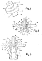
Figure 1 is partial median section of a servo valve, the open/close element of which is manufactured with the method according to the invention; -
Figure 2 is a perspective view of a component of the open/close element; -
Figure 3 is a partial median section of the open/close element ofFigure 1 , in a production step; -
Figure 4 is a median section of a servo valve according to a variant ofFigure 1 ; -
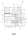
Figure 5 is a portion ofFigure 4 at an enlarged scale; and -
Figure 6 is a partial median section of the open/close element ofFigure 4 , in a production step. - With reference to
Figure 1 , designated as a whole by 2 is a hollow body or casing of a fuel injector for an internal-combustion engine, in particular a diesel engine. Thecasing 2 extends along a longitudinal axis and terminates with a nozzle, or nebulizer (not visible in the figure) for injection of the fuel at a high pressure. - The
casing 2 has anaxial cavity 34, housed in which is adosage servo valve 5, comprising a valve body 7 having an axial hole, in which a rod for control of injection (not visible inFigure 1 either) is able to slide. This rod is controlled by the pressure of the fuel in a control chamber, which is contained in the valve body 7 and is not visible inFigure 1 either. Housed in a portion of thecavity 34 is anelectric actuator 15, comprising anelectromagnet 16, designed to control ananchor 17 in the form of a notched disk. In particular, theelectromagnet 16 comprises amagnetic core 19, which has apolar surface 20 perpendicular to the axis of thecasing 2 and is held in position by a support orjacket 21. - The
electric actuator 15 has anaxial cavity 22 in communication with the discharge of theservo valve 5 towards the usual fuel tank. Housed in thecavity 22 is ahelical compression spring 23, pre-loaded so as to exert an action of thrust on theanchor 17 in a direction opposite to the attraction exerted by theelectromagnet 16. Thespring 23 acts on theanchor 17 through an intermediate body, designated as a whole by 12a, which comprises aflange 24 made of a single piece with apin 12 for guiding one end of thespring 23. Set between aplane top surface 17a of theanchor 17 and thepolar surface 20 of thecore 19 is athin lamina 13 made of nonmagnetic material in order to guarantee a certain gap between theanchor 17 and thecore 19. - The valve body 7 comprises a
flange 33 housed in thecavity 34 and kept fixed, in a fluid-tight way, against a shoulder (not visible in the figure) by a threadedring nut 36, screwed on aninternal thread 37 of thecavity 34. Theanchor 17 is associated to a bushing 41, guided axially by anaxial stem 38, which is made of a single piece with theflange 33 of the valve body 7 and extends in cantilever fashion from theflange 33 itself towards thecavity 22. Thestem 38 has a cylindricallateral surface 39, which guides axial sliding of thebushing 41. In particular, thebushing 41 has a cylindricalinternal surface 40, coupled to thelateral surface 39 of thestem 38 substantially in a fluid-tight way, for example with a diametral play of less than 4 µm, or else by means of interposition of annular seal elements. - The control chamber of the body 7 has an
outlet duct 43 for the fuel, made axially inside theflange 33 and thestem 38. Theduct 43 is in communication with at least one substantially radial stretch ofduct 44. Advantageously, two or moreradial stretches 44 can be provided, set at constant angular distances apart, which give out into anannular chamber 46, formed by a groove of thelateral surface 39 of thestem 38. InFigure 1 , twostretches 44 are provided, inclined in the direction of theanchor 17. - The
annular chamber 46 is obtained in an axial position adjacent to theflange 33 and is opened/closed by a terminal portion of thebushing 41, which forms the open/close element 47 for saidannular chamber 46 and hence also for the radial stretches ofduct 44. The open/close element 47 is consequently made of a single piece with thebushing 41 and co-operates with a corresponding stop for closing theservo valve 5. In particular, the open/close element 47 terminates with a stretch having an internal surface shaped like atruncated cone 45 flared downwards and designed to stop against a connector shaped like atruncated cone 49 set between theflange 33 and thestem 38. - Advantageously, the
connector 49 has two surface portions shaped like atruncated cone annular groove 50, which has a cross section shaped substantially like a right angle. The surface shaped like atruncated cone 45 of the open/close element 47 engages in a fluid-tight way the portion of surface shaped like atruncated cone 49a, against which it stops in the closing position. On account of the wear between thesesurfaces close element 47 requires a greater travel of thebushing 41 towards theconnector 49, always defining, as maximum diameter of the surface, the diameter of the cylindrical stretch of theannular groove 50. - The
anchor 17 is made of a magnetic material and is formed by a distinct piece, i.e., a piece separate from thebushing 41. It has acentral portion 56 having aplane bottom surface 57 and a notchedannular portion 58, with cross section tapered outwards. Thecentral portion 56 has anaxial hole 59, by means of which theanchor 17 engages with a certain radial play along an axial portion of thebushing 41, formed by acollar 61 obtained on aflange 60 of thebushing 41. Thecollar 61 has a smaller diameter than thebushing 41 and hence also than theflange 60. - The
flange 24 of theintermediate body 12a has aplane surface 65, designed to engage asurface 17a of theanchor 17 opposite to thesurface 57. Thebushing 41 is made of a single piece with a first stop element of theanchor 17, constituted by ashoulder 62, formed between thecollar 61 and theflange 60 of thebushing 41. In addition, theintermediate body 12a comprises anaxial pin 63 for connection of thebushing 41, which is made of a single piece with theflange 24 and must be fixed rigidly to thebushing 41 so that thesurface 65 of theflange 24 of theintermediate body 12a is fixed with respect to thebushing 41. Theconnection pin 63 is designed to be housed in acorresponding seat 40a of thebushing 41. Theseat 40a has a diameter slightly greater than theinternal surface 40 of thebushing 41, in order to reduce the portion to be ground to ensure fluid tightness with thesurface 39 of thestem 38. - Between the
surface 39 of thestem 38 and thesurface 40 of thebushing 41 there occurs in general a certain leakage of fuel, which leaks out into acompartment 48 between the end of thestem 39 and theconnection pin 63. In order to enable discharge of the fuel leaking into thecompartment 48 towards thecavity 22, theintermediate body 12a is provided with anaxial hole 64. - The
connection pin 63 extends axially from theplane surface 65 of theflange 24 in a direction opposite to theguide pin 12. In turn, theshoulder 62 is set in a position such as to create for theanchor 17 an axial play of a pre-set amount to enable a relative axial displacement between theanchor 17 and thebushing 41. The distance or space between thesurface 65 of theflange 24 and theshoulder 62 of thebushing 41 constitutes the housing of theanchor 17. Theplane surface 65 of theflange 24 bears upon an end surface oredge 66 of thecollar 61 of thebushing 41 so that the housing of theanchor 17 is uniquely defined. - Normally, the
anchor 17 rests against theshoulder 62 in the position indicated inFigure 1 . Thesurface 65 of theflange 24 projects from thelamina 13 downwards by a distance equal to a certain travel, or lift, of the open/close element 47. Thebushing 41 can be drawn axially by theanchor 17 upwards when the latter engages theflange 24. Theanchor 17 can, however, perform a travel greater than the travel of thebushing 41; i.e., it can perform along thecollar 61 an overtravel equal to the aforesaid play, between the two stop elements represented by theshoulder 62 of thebushing 41 and by thesurface 65 of theflange 24. - When the
electromagnet 16 is not energized, the open/close element 47 is held, by thespring 23 acting on thebody 12a, resting with its surface shaped like atruncated cone 45 against the portion shaped like atruncated cone 49a of theconnector 49 so that theservo valve 5 is closed. Normally, theanchor 17 is detached from thelamina 13 and rests against theshoulder 62. In theannular chamber 46 there is hence set up a pressure of the fuel, the value of which is equal to the supply pressure of the injector. - When the
electromagnet 16 is energized to perform an opening stroke of theservo valve 5, thecore 19 attracts theanchor 17, which at the start performs a loadless travel, until it is brought into contact with thesurface 65 of theflange 24, without affecting the displacement of thebushing 41. Next, the action of theelectromagnet 16 on theanchor 17 overcomes the force of thespring 23 and, via theflange 24 and the fixingpin 63, draws thebushing 41 towards the core 19 so that the open/close element 47 opens theservo valve 5. - When energization of the
electromagnet 16 ceases, thespring 23, via thebody 12a, causes thebushing 41 to perform the travel towards the closing position of theservo valve 5. During a first stretch of this closing travel, theflange 24, with thesurface 65, draws theanchor 17 along with it, which hence moves together with thebushing 41. At the end of its travel, the open/close element 47 impacts with itsconical surface 45 against the portion of surface shaped like atruncated cone 49a of theconnector 49 of the valve body 7. - On account of the type of stresses involved, the small area of contact, and the hardness of the open/
close element 47 and of the valve 7, after impact, the open/close element 47 rebounds overcoming the action of thespring 23. Instead, theanchor 17 continues its travel towards the valve body 7, recovering the play that is formed between theplane surface 57 of theportion 56 of theanchor 17 and theshoulder 62 of theflange 60. After a certain time from the first impact of the open/close element 47, theanchor 17 continues its travel towards the valve body 7 until there is an impact of theplane surface 57 of theportion 56 against theshoulder 62 of thebushing 41. As a result of this impact, the rebounds of thebushing 41 are markedly reduced or even eliminated. - By appropriately sizing the weights of the
anchor 17 and of thebushing 41, the travel of theanchor 17, and the travel of the open/close element 47, it is possible to obtain impact of theanchor 17 against thebushing 41 during the first rebound, immediately following upon de-energization of theelectromagnet 16 so that both the first rebound and the rebounds subsequent to the first rebound are attenuated. The impact between theanchor 17 and theshoulder 62 of thebushing 61 can also occur upon return of the open/close element 47 into the closing position, following upon the first rebound. In this case, the rebounds of the open/close element 47 subsequent to the first rebound are completely blocked. - Advantageously, the
intermediate body 12a is fixed on thebushing 41 by means of an appropriately shapedwelding device 70, indicated by dashed lines inFigure 3 . The weld is performed on the surface of theseat 40a along a circumference of continuous contact so that welding is carried out without any need for phasing between thedevice 70 and theintermediate body 12a. In particular, the circumference of continuous contact is constituted between asharp edge 69 of anend surface 71 of theconnection pin 63 and theseat 40a of theconnection pin 63 itself, when thesurface 65 of theflange 24 is brought into contact with theedge 66 of thebushing 41 so that thedevice 70 acts inside thebushing 41. - The method for manufacturing the open/
close element 47 of theservo valve 5 ofFigures 1-3 is performed as described in what follows. - First, the
anchor 17 is provided with thecentral guide hole 59, and thebushing 41 is provided with aguide portion 61 and theshoulder 62. Then theintermediate body 12a is provided with theflange 24 for supporting thespring 23, and with theconnection pin 63. Then theanchor 17 with thehole 59 is fitted on thecollar 61 of thebushing 41, and the fixingpin 63 is inserted into theseat 40a on thebushing 41 so as to bring thesurface 65 of theflange 24 into contact with theedge 66 of thebushing 41. - Finally, via the welding device 70 (see also
Figure 3 ), theintermediate body 12a is welded to thebushing 41 along the circumference of contact between thesharp edge 69 of theend surface 71 of theconnection pin 63 and theseat 40a of thebushing 41 that receives saidpin 63. In this way, on the circumference of contact aweld bead 72 is formed, which does not modify the external profile of thebushing 41 of theintermediate body 12a, nor does it alter thesurfaces stem 38 or of thebushing 41, in particular, nor is the profile of the housing for theanchor 17 altered. - In the variant of
Figures 4 and5 , the parts that are similar to the ones of the embodiment illustrated inFigures 1-3 are designated by the same reference numbers and will not be described any further herein. InFigure 4 , theanchor 17 has a constant thickness for the twoportions shoulder 62 is not made on a flange, but on the thickness of thebushing 41. - Removably inserted between the
bottom surface 57 of theanchor 17 and theshoulder 62 of thebushing 41 is a ring of calibrated thickness, in particular a C-shaped ring 73 (see alsoFigure 5 ), which is housed in anannular groove 74 adjacent to theshoulder 62. Consequently, the stop element of theanchor 17 for closing the open/close element 47 is here constituted by asurface 75 of the C-shapedring 73 opposite to theshoulder 62. Advantageously, the C-shapedring 73 can have a thickness chosen from a series of modular classes of C-shaped rings of calibrated thicknesses in order to adjust the additional travel of theanchor 17, i.e., the relative play between the twostop elements - As regards the corresponding manufacturing method, before the
pin 63 of theintermediate body 12a is inserted into theseat 40a of thebushing 41, theanchor 17 with thehole 59 is fitted on thecollar 61 so as to enable theanchor 17 itself to rest against theshoulder 62, remaining with thesurface 17a set at a distance from theend edge 66 of thebushing 41. - Then the
intermediate body 12a with thepin 63 is inserted into theseat 40a so as to bring thesurface 65 of theflange 24 into contact with theedge 66 of thecollar 61. Then, by means of an appropriately shapedwelding device 77, indicated by dashed lines inFigure 6 , theintermediate body 12a is welded to thecollar 61 along a circumference of continuous contact between asharp edge 76 of theedge 66 and thesurface 65 of theflange 24. In this way, on the circumference of contact, aweld bead 78 is formed, in a position corresponding to which thehole 59 of theanchor 17 has a flaring 79 so that after welding the travel of theanchor 17 is not altered with respect to the travel before welding. - Finally, by displacing the
anchor 17 towards theflange 24, the C-shapedring 73 is inserted into thegroove 74 so that theanchor 17 has, with the C-shapedring 73, the desired play, corresponding to the difference between its travel and the travel of the open/close element 47 and hence also of thebushing 41. - The method for manufacturing the open/
close element 47 of theservo valves 5, according to the variants of the invention described, is hence characterized by the following steps: - the
bushing 41 is provided with aguide portion 61 designed to engage theguide hole 59 for a relative displacement of theanchor 17 between twostop elements bushing 41 being equipped with at least one 62, 75 of saidstop elements - an
intermediate body 12a is provided, comprising aflange 24 for supporting saidspring 23 and aconnection pin 63 that can be inserted into aseat 40a arranged in saidguide portion 61; - said
anchor 17 is fitted on saidguide portion 61; - said
intermediate body 12a is inserted with saidpin 63 into saidseat 40a so as to bring saidflange 24 into contact with anedge 66 of saidguide portion 61; and - by means of a
welding device intermediate body 12a is welded on saidguide portion 61 along acircumference intermediate body 12a with thewelding device - From what has been seen above, the advantages of the manufacturing method according to the invention as compared to the known art emerge clearly. In particular, the welding can be performed without any discontinuity along the
circumference intermediate body 12a and thewelding device Figure 1 , theweld bead 72 does not cause any variation of the external profile of thebushing 41 and of theflange 24. In the variant ofFigure 4 , in a position corresponding to thebead 78, theanchor 17 has the flaring 79, which does not alter sliding between theanchor 17 and thecollar 61. - It may be understood that various modifications and improvements may be made to the manufacturing method described above, without thereby departing from the scope of the claims. For example, in the variant of
Figure 1 , thestop 62 can be represented by a C-shaped ring mounted removably on thebushing 41. In addition, in the variant ofFigures 4 and5 , between theanchor 17 and the C-shapedring 73 there can be set an additional ring with modular calibrated thickness. Also the flaring 79 of thehole 59 of theanchor 17 can be replaced by a flaring of theend edge 66 of thecollar 61. Finally, in the method for the production of the open/close element ofFigure 6 , using thesame device 77, the C-shapedring 73 can be welded on thecollar 61 or on the shoulder of thebushing 41, immediately after fitting thereof on thebushing 41. - The
weld beads close element 47, during production, could be a separate piece fixed to the remaining part of thebushing 41.
Claims (13)
- A method for manufacturing an open/close element for a balanced servo valve (5) of a fuel injector, wherein the open/close element (47) is fixed with respect to a bushing (41) designed to move for a certain axial travel along a fixed stem (38) for opening/closing said servo valve (5); a discharge duct (43, 44) of the servo valve (5) giving out onto a lateral surface (39) of said stem (38), a spring (23) being designed to keep said bushing (41) in the closing position, where said bushing (41) is subject to a substantially zero axial pressure; said bushing (41) being movable under the control of an anchor (17) actuated by an electric actuator (15) against the action of said spring (23); said anchor (17) being provided with a central hole (59) and being axially movable for a travel greater than said certain travel;
said method comprising the following steps:- an intermediate body (12a) is provided, comprising a flange (24) for supporting said spring (23) and a connection pin (63) that can be inserted into a seat (40a) arranged in said bushing (41);- said anchor (17) is fitted on a guide portion (61) of said bushing (41);- said intermediate body (12a) is fitted on said bushing (41) so as to bring said flange (24) into contact with an edge (66) of said guide portion (61); and- said intermediate body (12a) is welded by means of a welding device (70, 77) on said guide portion (61) along a circumference of continuous contact (69, 76) so that welding is carried out without any need for phasing of the intermediate body (12a) with the welding device (70, 77). - The manufacturing method according to Claim 1, characterized in that said intermediate body (12a) is moreover provided with a guide pin (12) for guiding an end of said spring (23), said guide pin (12) being coaxial to said connection pin (63) and opposite to the latter.
- The manufacturing method according to Claim 1 or Claim 2, characterized in that said guide portion is formed by a collar (61) of said bushing (41) set between a shoulder (62) of said bushing and said edge (66).
- The manufacturing method according to Claim 3, characterized in that one of said stop elements (62, 75; 65) is formed by a surface (65) of said flange (24).
- The manufacturing method according to one of the preceding claims, characterized in that said circumference (69) of continuous contact is brought, by an end edge (71) of said connection pin (63), into contact with said seat (40a).
- The manufacturing method according to Claims 3 and 5, characterized in that the other of said stop elements is constituted by said shoulder (62) of said bushing (41).
- The manufacturing method according to any of Claims 1 to 4, characterized in that set between said shoulder (62) and said anchor (17) is a ring (73) of a thickness chosen from classes of a modular thickness.
- The manufacturing method according to Claims 7 and 4, characterized in that said surface (65) of said flange (24) is designed to set itself in contact with said end edge (66), said circumference of continuous contact being constituted by a sharp edge (76) of said end edge (66) in contact with said surface (65).
- The manufacturing method according to Claim 7 or Claim 8, characterized in that said ring of thickness is formed by a removable ring (73), designed to block said anchor (17) on said bushing (41), said removable ring (73) being fitted on said bushing (41) after said welding.
- The manufacturing method according to Claim 9, characterized in that said removable ring is a C-shaped ring (73) set in an annular groove (74) of said bushing (41) adjacent to said guide portion (61).
- The manufacturing method according to Claim 10, characterized in that the other of said stop elements (62, 75; 65) is formed by said C-shaped ring (73).
- The manufacturing method according to Claim 9, characterized in that said ring of thickness is a C-shaped ring (73) and is in turn welded in a position corresponding to the surface (62) or the collar (61), after its insertion.
- An open/close element for a balanced servo valve of a fuel injector, manufactured applying the method according to one of the preceding claims.
Priority Applications (3)
| Application Number | Priority Date | Filing Date | Title |
|---|---|---|---|
| AT09425058T ATE505642T1 (en) | 2009-02-16 | 2009-02-16 | METHOD FOR PRODUCING AN OPEN/CLOSE ELEMENT FOR BALANCED FUEL INJECTOR SERVO VALVES |
| EP09425058A EP2218902B1 (en) | 2009-02-16 | 2009-02-16 | Method for manufacturing an open/close element for balanced servo valves of a fuel injector. |
| DE602009001092T DE602009001092D1 (en) | 2009-02-16 | 2009-02-16 | A method of manufacturing an open / close element for balanced servo valves of fuel injectors |
Applications Claiming Priority (1)
| Application Number | Priority Date | Filing Date | Title |
|---|---|---|---|
| EP09425058A EP2218902B1 (en) | 2009-02-16 | 2009-02-16 | Method for manufacturing an open/close element for balanced servo valves of a fuel injector. |
Publications (2)
| Publication Number | Publication Date |
|---|---|
| EP2218902A1 EP2218902A1 (en) | 2010-08-18 |
| EP2218902B1 true EP2218902B1 (en) | 2011-04-13 |
Family
ID=40810738
Family Applications (1)
| Application Number | Title | Priority Date | Filing Date |
|---|---|---|---|
| EP09425058A Active EP2218902B1 (en) | 2009-02-16 | 2009-02-16 | Method for manufacturing an open/close element for balanced servo valves of a fuel injector. |
Country Status (3)
| Country | Link |
|---|---|
| EP (1) | EP2218902B1 (en) |
| AT (1) | ATE505642T1 (en) |
| DE (1) | DE602009001092D1 (en) |
Families Citing this family (3)
| Publication number | Priority date | Publication date | Assignee | Title |
|---|---|---|---|---|
| DE102011086951A1 (en) * | 2011-11-23 | 2013-05-23 | Robert Bosch Gmbh | Armature assembly, solenoid valve and fuel injector |
| FR3010148B1 (en) * | 2013-09-05 | 2015-09-25 | Peugeot Citroen Automobiles Sa | FUEL INJECTOR CONTROL VALVE FOR COMMON INJECTION RAMP AND CORRESPONDING INJECTOR |
| DE102014207937A1 (en) * | 2014-04-28 | 2015-10-29 | Robert Bosch Gmbh | Solenoid valve for a fuel injection system |
Family Cites Families (5)
| Publication number | Priority date | Publication date | Assignee | Title |
|---|---|---|---|---|
| US5299776A (en) * | 1993-03-26 | 1994-04-05 | Siemens Automotive L.P. | Impact dampened armature and needle valve assembly |
| DE10133450A1 (en) * | 2001-07-10 | 2003-01-30 | Bosch Gmbh Robert | Solenoid valve with plug-in rotary connection |
| DE602005021310D1 (en) * | 2005-03-14 | 2010-07-01 | Fiat Ricerche | Adjustable metering valve of an injector and its adjustment method |
| DE102006021741A1 (en) * | 2006-05-10 | 2007-11-15 | Robert Bosch Gmbh | Fuel injector with pressure compensated control valve |
| ATE445777T1 (en) * | 2007-07-30 | 2009-10-15 | Fiat Ricerche | INJECTOR WITH BALANCED GAUGE SERVO VALVE FOR AN INTERNAL COMBUSTION ENGINE |
-
2009
- 2009-02-16 AT AT09425058T patent/ATE505642T1/en not_active IP Right Cessation
- 2009-02-16 EP EP09425058A patent/EP2218902B1/en active Active
- 2009-02-16 DE DE602009001092T patent/DE602009001092D1/en active Active
Also Published As
| Publication number | Publication date |
|---|---|
| DE602009001092D1 (en) | 2011-05-26 |
| ATE505642T1 (en) | 2011-04-15 |
| EP2218902A1 (en) | 2010-08-18 |
Similar Documents
| Publication | Publication Date | Title |
|---|---|---|
| EP1707798B1 (en) | Adjustable metering servovalve for a fuel injector, and relative adjustment method | |
| EP2318686B1 (en) | Fuel injector servovalve | |
| US7740187B2 (en) | Internal combustion engine fuel injector | |
| EP1621764B1 (en) | Internal combustion engine fuel injector | |
| US7784711B2 (en) | Metering servovalve and fuel injector for an internal combustion engine | |
| KR100957199B1 (en) | Fuel injector with balanced metering servovalve, for an internal combustion engine | |
| EP1918568B1 (en) | Metering solenoid valve for a fuel injector | |
| US6126094A (en) | Internal combustion engine fuel injector | |
| US6793158B2 (en) | Internal combustion engine fuel injector | |
| EP2218902B1 (en) | Method for manufacturing an open/close element for balanced servo valves of a fuel injector. | |
| EP1284358B1 (en) | Internal combustion engine fuel injector and its manufacturing method | |
| EP2218904B1 (en) | Method for manufacturing a fuel injector servo valve | |
| EP2218901B1 (en) | Method for manufacturing an open/close element for servo valves of a fuel injector | |
| EP2218903B1 (en) | Method for manufacturing a fuel injector servo valve | |
| US11415093B2 (en) | Electromagnetic fuel injection valve | |
| EP2221470B1 (en) | Method for manufacturing a fuel injector servo valve | |
| KR102615468B1 (en) | Control valve device of fuel injector | |
| EP3377754B1 (en) | Fuel injector |
Legal Events
| Date | Code | Title | Description |
|---|---|---|---|
| PUAI | Public reference made under article 153(3) epc to a published international application that has entered the european phase |
Free format text: ORIGINAL CODE: 0009012 |
|
| 17P | Request for examination filed |
Effective date: 20091012 |
|
| AK | Designated contracting states |
Kind code of ref document: A1 Designated state(s): AT BE BG CH CY CZ DE DK EE ES FI FR GB GR HR HU IE IS IT LI LT LU LV MC MK MT NL NO PL PT RO SE SI SK TR |
|
| AX | Request for extension of the european patent |
Extension state: AL BA RS |
|
| GRAP | Despatch of communication of intention to grant a patent |
Free format text: ORIGINAL CODE: EPIDOSNIGR1 |
|
| GRAS | Grant fee paid |
Free format text: ORIGINAL CODE: EPIDOSNIGR3 |
|
| GRAA | (expected) grant |
Free format text: ORIGINAL CODE: 0009210 |
|
| AK | Designated contracting states |
Kind code of ref document: B1 Designated state(s): AT BE BG CH CY CZ DE DK EE ES FI FR GB GR HR HU IE IS IT LI LT LU LV MC MK MT NL NO PL PT RO SE SI SK TR |
|
| REG | Reference to a national code |
Ref country code: GB Ref legal event code: FG4D |
|
| REG | Reference to a national code |
Ref country code: CH Ref legal event code: EP |
|
| AKX | Designation fees paid |
Designated state(s): AT BE BG CH CY CZ DE DK EE ES FI FR GB GR HR HU IE IS IT LI LT LU LV MC MK MT NL NO PL PT RO SE SI SK TR |
|
| REG | Reference to a national code |
Ref country code: IE Ref legal event code: FG4D |
|
| REF | Corresponds to: |
Ref document number: 602009001092 Country of ref document: DE Date of ref document: 20110526 Kind code of ref document: P |
|
| REG | Reference to a national code |
Ref country code: DE Ref legal event code: R096 Ref document number: 602009001092 Country of ref document: DE Effective date: 20110526 |
|
| REG | Reference to a national code |
Ref country code: NL Ref legal event code: VDEP Effective date: 20110413 |
|
| LTIE | Lt: invalidation of european patent or patent extension |
Effective date: 20110413 |
|
| PG25 | Lapsed in a contracting state [announced via postgrant information from national office to epo] |
Ref country code: NO Free format text: LAPSE BECAUSE OF FAILURE TO SUBMIT A TRANSLATION OF THE DESCRIPTION OR TO PAY THE FEE WITHIN THE PRESCRIBED TIME-LIMIT Effective date: 20110713 Ref country code: SE Free format text: LAPSE BECAUSE OF FAILURE TO SUBMIT A TRANSLATION OF THE DESCRIPTION OR TO PAY THE FEE WITHIN THE PRESCRIBED TIME-LIMIT Effective date: 20110413 Ref country code: HR Free format text: LAPSE BECAUSE OF FAILURE TO SUBMIT A TRANSLATION OF THE DESCRIPTION OR TO PAY THE FEE WITHIN THE PRESCRIBED TIME-LIMIT Effective date: 20110413 Ref country code: PT Free format text: LAPSE BECAUSE OF FAILURE TO SUBMIT A TRANSLATION OF THE DESCRIPTION OR TO PAY THE FEE WITHIN THE PRESCRIBED TIME-LIMIT Effective date: 20110816 Ref country code: LT Free format text: LAPSE BECAUSE OF FAILURE TO SUBMIT A TRANSLATION OF THE DESCRIPTION OR TO PAY THE FEE WITHIN THE PRESCRIBED TIME-LIMIT Effective date: 20110413 |
|
| PG25 | Lapsed in a contracting state [announced via postgrant information from national office to epo] |
Ref country code: FI Free format text: LAPSE BECAUSE OF FAILURE TO SUBMIT A TRANSLATION OF THE DESCRIPTION OR TO PAY THE FEE WITHIN THE PRESCRIBED TIME-LIMIT Effective date: 20110413 Ref country code: BE Free format text: LAPSE BECAUSE OF FAILURE TO SUBMIT A TRANSLATION OF THE DESCRIPTION OR TO PAY THE FEE WITHIN THE PRESCRIBED TIME-LIMIT Effective date: 20110413 Ref country code: SI Free format text: LAPSE BECAUSE OF FAILURE TO SUBMIT A TRANSLATION OF THE DESCRIPTION OR TO PAY THE FEE WITHIN THE PRESCRIBED TIME-LIMIT Effective date: 20110413 Ref country code: IS Free format text: LAPSE BECAUSE OF FAILURE TO SUBMIT A TRANSLATION OF THE DESCRIPTION OR TO PAY THE FEE WITHIN THE PRESCRIBED TIME-LIMIT Effective date: 20110813 Ref country code: CY Free format text: LAPSE BECAUSE OF FAILURE TO SUBMIT A TRANSLATION OF THE DESCRIPTION OR TO PAY THE FEE WITHIN THE PRESCRIBED TIME-LIMIT Effective date: 20110413 Ref country code: LV Free format text: LAPSE BECAUSE OF FAILURE TO SUBMIT A TRANSLATION OF THE DESCRIPTION OR TO PAY THE FEE WITHIN THE PRESCRIBED TIME-LIMIT Effective date: 20110413 Ref country code: ES Free format text: LAPSE BECAUSE OF FAILURE TO SUBMIT A TRANSLATION OF THE DESCRIPTION OR TO PAY THE FEE WITHIN THE PRESCRIBED TIME-LIMIT Effective date: 20110724 Ref country code: AT Free format text: LAPSE BECAUSE OF FAILURE TO SUBMIT A TRANSLATION OF THE DESCRIPTION OR TO PAY THE FEE WITHIN THE PRESCRIBED TIME-LIMIT Effective date: 20110413 Ref country code: GR Free format text: LAPSE BECAUSE OF FAILURE TO SUBMIT A TRANSLATION OF THE DESCRIPTION OR TO PAY THE FEE WITHIN THE PRESCRIBED TIME-LIMIT Effective date: 20110714 |
|
| PG25 | Lapsed in a contracting state [announced via postgrant information from national office to epo] |
Ref country code: NL Free format text: LAPSE BECAUSE OF FAILURE TO SUBMIT A TRANSLATION OF THE DESCRIPTION OR TO PAY THE FEE WITHIN THE PRESCRIBED TIME-LIMIT Effective date: 20110413 |
|
| PG25 | Lapsed in a contracting state [announced via postgrant information from national office to epo] |
Ref country code: CZ Free format text: LAPSE BECAUSE OF FAILURE TO SUBMIT A TRANSLATION OF THE DESCRIPTION OR TO PAY THE FEE WITHIN THE PRESCRIBED TIME-LIMIT Effective date: 20110413 Ref country code: EE Free format text: LAPSE BECAUSE OF FAILURE TO SUBMIT A TRANSLATION OF THE DESCRIPTION OR TO PAY THE FEE WITHIN THE PRESCRIBED TIME-LIMIT Effective date: 20110413 |
|
| PLBE | No opposition filed within time limit |
Free format text: ORIGINAL CODE: 0009261 |
|
| STAA | Information on the status of an ep patent application or granted ep patent |
Free format text: STATUS: NO OPPOSITION FILED WITHIN TIME LIMIT |
|
| PG25 | Lapsed in a contracting state [announced via postgrant information from national office to epo] |
Ref country code: SK Free format text: LAPSE BECAUSE OF FAILURE TO SUBMIT A TRANSLATION OF THE DESCRIPTION OR TO PAY THE FEE WITHIN THE PRESCRIBED TIME-LIMIT Effective date: 20110413 Ref country code: PL Free format text: LAPSE BECAUSE OF FAILURE TO SUBMIT A TRANSLATION OF THE DESCRIPTION OR TO PAY THE FEE WITHIN THE PRESCRIBED TIME-LIMIT Effective date: 20110413 |
|
| 26N | No opposition filed |
Effective date: 20120116 |
|
| REG | Reference to a national code |
Ref country code: DE Ref legal event code: R097 Ref document number: 602009001092 Country of ref document: DE Effective date: 20120116 |
|
| PG25 | Lapsed in a contracting state [announced via postgrant information from national office to epo] |
Ref country code: MC Free format text: LAPSE BECAUSE OF NON-PAYMENT OF DUE FEES Effective date: 20120229 |
|
| REG | Reference to a national code |
Ref country code: IE Ref legal event code: MM4A |
|
| PG25 | Lapsed in a contracting state [announced via postgrant information from national office to epo] |
Ref country code: IE Free format text: LAPSE BECAUSE OF NON-PAYMENT OF DUE FEES Effective date: 20120216 |
|
| PG25 | Lapsed in a contracting state [announced via postgrant information from national office to epo] |
Ref country code: MK Free format text: LAPSE BECAUSE OF FAILURE TO SUBMIT A TRANSLATION OF THE DESCRIPTION OR TO PAY THE FEE WITHIN THE PRESCRIBED TIME-LIMIT Effective date: 20110413 |
|
| PG25 | Lapsed in a contracting state [announced via postgrant information from national office to epo] |
Ref country code: BG Free format text: LAPSE BECAUSE OF FAILURE TO SUBMIT A TRANSLATION OF THE DESCRIPTION OR TO PAY THE FEE WITHIN THE PRESCRIBED TIME-LIMIT Effective date: 20110713 |
|
| PG25 | Lapsed in a contracting state [announced via postgrant information from national office to epo] |
Ref country code: MT Free format text: LAPSE BECAUSE OF FAILURE TO SUBMIT A TRANSLATION OF THE DESCRIPTION OR TO PAY THE FEE WITHIN THE PRESCRIBED TIME-LIMIT Effective date: 20110413 |
|
| REG | Reference to a national code |
Ref country code: CH Ref legal event code: PL |
|
| GBPC | Gb: european patent ceased through non-payment of renewal fee |
Effective date: 20130216 |
|
| PG25 | Lapsed in a contracting state [announced via postgrant information from national office to epo] |
Ref country code: CH Free format text: LAPSE BECAUSE OF NON-PAYMENT OF DUE FEES Effective date: 20130228 Ref country code: LI Free format text: LAPSE BECAUSE OF NON-PAYMENT OF DUE FEES Effective date: 20130228 |
|
| PG25 | Lapsed in a contracting state [announced via postgrant information from national office to epo] |
Ref country code: GB Free format text: LAPSE BECAUSE OF NON-PAYMENT OF DUE FEES Effective date: 20130216 |
|
| PG25 | Lapsed in a contracting state [announced via postgrant information from national office to epo] |
Ref country code: TR Free format text: LAPSE BECAUSE OF FAILURE TO SUBMIT A TRANSLATION OF THE DESCRIPTION OR TO PAY THE FEE WITHIN THE PRESCRIBED TIME-LIMIT Effective date: 20110413 |
|
| PG25 | Lapsed in a contracting state [announced via postgrant information from national office to epo] |
Ref country code: LU Free format text: LAPSE BECAUSE OF NON-PAYMENT OF DUE FEES Effective date: 20120216 |
|
| PG25 | Lapsed in a contracting state [announced via postgrant information from national office to epo] |
Ref country code: HU Free format text: LAPSE BECAUSE OF FAILURE TO SUBMIT A TRANSLATION OF THE DESCRIPTION OR TO PAY THE FEE WITHIN THE PRESCRIBED TIME-LIMIT Effective date: 20090216 |
|
| REG | Reference to a national code |
Ref country code: FR Ref legal event code: PLFP Year of fee payment: 8 |
|
| REG | Reference to a national code |
Ref country code: FR Ref legal event code: PLFP Year of fee payment: 9 |
|
| PGFP | Annual fee paid to national office [announced via postgrant information from national office to epo] |
Ref country code: FR Payment date: 20170224 Year of fee payment: 9 |
|
| PGFP | Annual fee paid to national office [announced via postgrant information from national office to epo] |
Ref country code: IT Payment date: 20170202 Year of fee payment: 9 |
|
| PGFP | Annual fee paid to national office [announced via postgrant information from national office to epo] |
Ref country code: DE Payment date: 20170428 Year of fee payment: 9 |
|
| REG | Reference to a national code |
Ref country code: DE Ref legal event code: R119 Ref document number: 602009001092 Country of ref document: DE |
|
| REG | Reference to a national code |
Ref country code: FR Ref legal event code: ST Effective date: 20181031 |
|
| PG25 | Lapsed in a contracting state [announced via postgrant information from national office to epo] |
Ref country code: DE Free format text: LAPSE BECAUSE OF NON-PAYMENT OF DUE FEES Effective date: 20180901 |
|
| PG25 | Lapsed in a contracting state [announced via postgrant information from national office to epo] |
Ref country code: FR Free format text: LAPSE BECAUSE OF NON-PAYMENT OF DUE FEES Effective date: 20180228 Ref country code: IT Free format text: LAPSE BECAUSE OF NON-PAYMENT OF DUE FEES Effective date: 20180216 |